Embed Size (px)
Citation preview
Rev 01, 3/12/2007
OVERVIEW OF THE SEISMIC INFORMATION RELATING TO A 4S NUCLEAR REACTOR BASED
POWER GENERATION FACILITY IN GALENA, ALASKA
Prepared by the City of Galena, Alaska

2 3/23/2007
I. EXECUTIVE SUMMARY .................................................................................................... 3
II. BACKGROUND ..................................................................................................................... 3
A. The City of Galena.............................................................................................................. 3
B. The Galena Power Supply .................................................................................................. 3
C. The Galena 4S Project ........................................................................................................ 4
D. Features of the 4S Reactor .................................................................................................. 4
E. White Paper Objectives....................................................................................................... 6
III. RELEVANT REGULATIONS AND REGULATORY GUIDANCE................................ 6
IV. BOUNDING SEISMIC CHARACTERISTICS OF THE GALENA SITE ...................... 7
V. SEISMIC ISOLATION IN THE 4S NPF DESIGN........................................................... 12
B. Seismic Isolation in the 4S Design ................................................................................... 13
VI. CONCLUSIONS ................................................................................................................... 17
VII. RECOMMENDATIONS................................................................................................ 17
APPENDIX A, RELEVANT FIGURES...…………………………………………………….18
3 3/23/2007
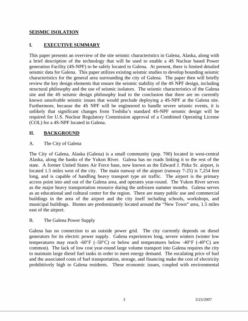
SEISMIC ISOLATION
I. EXECUTIVE SUMMARY
This paper presents an overview of the site seismic characteristics in Galena, Alaska, along with a brief description of the technology that will be used to enable a 4S Nuclear based Power generation Facility (4S-NPF) to be safely located in Galena. At present, there is limited detailed seismic data for Galena. This paper utilizes existing seismic studies to develop bounding seismic characteristics for the general area surrounding the city of Galena. The paper then will briefly review the key design elements that ensure the seismic stability of the 4S NPF design, including structural philosophy and the use of seismic isolators. The seismic characteristics of the Galena site and the 4S seismic design philosophy lead to the conclusion that there are no currently known unsolvable seismic issues that would preclude deploying a 4S-NPF at the Galena site. Furthermore, because the 4S NPF will be engineered to handle severe seismic events, it is unlikely that significant changes from Toshiba’s standard 4S-NPF seismic design will be required for U.S. Nuclear Regulatory Commission approval of a Combined Operating License (COL) for a 4S-NPF located in Galena.
II. BACKGROUND
A. The City of Galena
The City of Galena, Alaska (Galena) is a small community (pop. 700) located in west-central Alaska, along the banks of the Yukon River. Galena has no roads linking it to the rest of the state. A former United States Air Force base, now known as the Edward J. Pitka Sr. airport, is located 1.5 miles west of the city. The main runway of the airport (runway 7-25) is 7,254 feet long, and is capable of handling heavy transport type air traffic. The airport is the primary access point into and out of the Galena area, and operates year-round. The Yukon River serves as the major heavy transportation resource during the unfrozen summer months. Galena serves as an educational and cultural center for the region. There are many public use and commercial buildings in the area of the airport and the city itself including schools, workshops, and municipal buildings. Homes are predominately located around the “New Town” area, 1.5 miles east of the airport.
B. The Galena Power Supply
Galena has no connection to an outside power grid. The city currently depends on diesel generators for its electric power supply. Galena experiences long, severe winters (winter low temperatures may reach -60°F (–50°C) or below and temperatures below -40°F (-40°C) are common). The lack of low cost year-round large volume transport into Galena requires the city to maintain large diesel fuel tanks in order to meet energy demand. The escalating price of fuel and the associated costs of fuel transportation, storage, and financing make the cost of electricity prohibitively high to Galena residents. These economic issues, coupled with environmental

4 3/23/2007
pollution concerns, make it prudent for Galena to explore alternative ways to meet its energy needs.1
C. The Galena 4S Project
In 2004, Galena received presentations from Toshiba Corporation (Toshiba) on a “Super-Safe, Small and Simple (4S)” NPF. The 4S reactor was developed jointly by Toshiba and the Central Research Institute of Electric Power Industry (CRIEPI) of Japan.2 Following those presentations, Galena secured the preparation of a U.S. Department of Energy (DOE) sponsored study on ways to meet Galena’s power requirements.3 The study included analyses of the thermal and electric load profiles for Galena, technologies available to meet those loads (the technologies evaluated in detail were enhanced diesel power, coal, and a 4S reactor-based facility, which were determined to be the only viable alternatives), the environmental and regulatory issues associated with each of these technologies, and the overall economics of each energy option. The DOE study concluded that the 4S reactor-based power facility is the best economic and environmental choice for Galena.
On December 14, 2004, the Galena City Council passed a resolution calling for the deployment of a 4S reactor-based power generation facility in the community. The resolution stated, among other things, that: "It is in the public interest to pursue the siting of a Toshiba 4S nuclear battery in Galena." The council further directed the City Manager to "establish a process and timeline leading to evaluations, industrial partners, and financial and contractual arrangements necessary to bring the economic and environmental benefits of the 4S to Galena."
Since the passing of the resolution, Galena has been investigating the regulatory and economic feasibility of locating a 10 megawatt-electric (“MWe”) 4S NPF in Galena. In parallel, Toshiba has been developing a preliminary design document to submit to the U.S. Nuclear Regulatory Commission (NRC) for its review.4 In order to move the siting evaluation process forward and open lines of communication with various stakeholders and the NRC, Galena has commissioned a set of white papers that discuss important aspects of the small nuclear power facility project including a General Overview, Nuclear Liability, Emergency Planning, Safety and Security, Decommissioning, Containment, and Seismic Isolation. This paper is part of the white paper series. D. Features of the 4S Reactor
1 Adams Atomic Engines, Inc., Atomic Insights, “Nuclear Power for Galena, Alaska” (March 2005), available
online at http://www.atomicinsights.com/AI_03-20-05print.html. 2 See, e.g., http://www.uaf.edu/aetdl/Presentations.htm. 3 Robert E. Chaney et al., “Galena Electric Power- A Situational Analysis” ( DE- AM26-99FT40575) (December
2004). Science Applications International Corporation (SAIC) coordinated the study, in which the University of Alaska and Idaho National Engineering and Environmental Laboratory participated.
4“Galena Project Officials Gear Up for Pre-Application Activities,” Inside NRC, February 6, 2006.

5 3/23/2007
The 4S design introduces a small liquid metal nuclear reactor to the commercial power industry in the United States. Liquid metal reactors (LMRs) have been operated successfully worldwide and have been used in the United States at test facilities, with over 300 reactor years of operational experience. The small, advanced design of the 4S has several important operational and safety advantages, particularly for remote location deployment, when compared to the large light-water commercial nuclear power plants currently operating in the United States. The reactor thermal output at peak power of a 10 MWe 4S NPF is approximately 30MW thermal (MWt), which is small fraction of the power output of a standard sized commercial reactor. Important features of the design of the 4S include:
− Modular construction, which will reduce costs and construction time − Nuclear systems that are installed below grade, resulting in safety and security
benefits − Liquid sodium coolant, which does not react with core internals or piping − Reactor coolant that is not highly pressurized, which minimizes stresses on the plant
systems − Passive safety systems that do not depend on emergency power to function − Negative reactivity temperature coefficients, including coolant void reactivity, which
slow down the reaction rates in the core as temperatures rise, preventing an over-temperature condition
− Air-cooled reactor vessel, steam generator and condenser; no condenser coolant water, intake structures, or continuous outside water supply are required
− 30-year core life and fuel cycle, which avoids the need to refuel, eliminates fuel storage, and minimizes fuel handling concerns
− Capability of load following (i.e., matching the reactor power level to the external electrical power demand) without mechanical operation of the reactor control system
− Continuous containment of all radioactive materials within the reactor module throughout the life of the plant.
These features provide the 4S reactor system with significant benefits in operational capability, physical security, and protection of public safety. Many of the systems that increase cost, raise safety concerns, and pose potential security hazards at current plants (such as use of numerous mechanical pumps and valves, the need for a spent fuel pool, and the reliance upon high and low pressure water injection systems) have been eliminated in the design of the 4S. While the 4S NPF design raises some new issues, such as the need to deal with highly reactive liquid sodium and potential accident scenarios involving sodium-water interaction, these issues have been addressed in the 4S system design and in past LMR facilities. On balance, the licensing of a 4S NPF should be a relatively straightforward process, provided that good communications are maintained between all parties involved and there is a timely flow of complete and accurate technical information.

6 3/23/2007
E. White Paper Objectives
The “white papers” in this series are part of an effort underwritten by the State of Alaska to provide “expert legal and technical analysis for [a] proposed mini-nuclear plant” at Galena. The objectives of the papers are threefold: (1) to discuss some of the more important issues that will need to be addressed by the NRC in its consideration of applications for an early site permit (ESP) and a combined construction/operating license (COL) for a 4S NPF located in Galena; (2) to identify approaches for handling issues to ensure that the overall cost of operating a 4S NPF in Galena is competitive with alternative electric power generation methods; and (3) to increase the awareness of government officials and the general public regarding the process for obtaining authorization from the NRC to construct and operate a 4S NPF in Galena. Ultimately, Galena must determine if proceeding with the licensing and construction of a 4S reactor is economically justified. These papers are intended to assist the City in making that determination.
The main purpose of this white paper is to identify the seismic considerations that would be associated with locating a 4S NPF in Galena. While the paper does not address in detail the seismic considerations that will have to be examined to support the licensing of such a facility, the methods and bounding parameters involved in such an analysis will be discussed.
III. RELEVANT REGULATIONS AND REGULATORY GUIDANCE
• The NRC's 10 CFR Part 52 to Title 10 of the Code of Federal Regulations provides a predictable licensing process including certification of new nuclear plant designs. The design certification process provides for early public participation and resolution of safety issues prior to an application to construct a Nuclear power plant.
• The NRC's "Statement of Policy for Regulation of Advanced Nuclear Power Plants," dated July 8, 1986, encourages early discussions, before a license application, between NRC and reactor designers to provide licensing guidance. In June 1988, the NRC issued NUREG-1226, "Development and Utilization of the NRC Policy Statement on the Regulation of Advanced Nuclear Power Plants." This document provides guidance on the implementation of the policy and describes the approach used by NRC in its review of advanced reactor design concepts.
• US NRC Regulatory Guide (Reg. Guide) 1.165 Procedure (with Appendix A-F) is guidance for determining controlling earthquakes. Three types of earthquakes are identified in this guidance for considering the location of a reactor: safe-shutdown earthquakes (SSE), operating basis earthquakes (OBE), and design-basis earthquakes (DBE). A facility’s design must be demonstrated to be able to withstand a DBE before a license is granted. For this study, the scenario earthquakes for a 4S NPF located in Galena will be developed using the procedure outlined in Reg. Guide 1.165. This procedure is based on a de-aggregation of the probabilistic seismic hazard in terms of earthquake magnitudes and distances.
• 10 CFR Part 100, "Reactor Site Criteria," Section 100.23, "Geologic and Seismic Siting Factors," paragraph (c), "Geological, Seismological, and Engineering Characteristics," requires that the geological, seismological, and engineering characteristics of a site and

7 3/23/2007
its environs be investigated in sufficient scope and detail to permit an adequate evaluation of the proposed site, to provide sufficient information to support evaluations performed to arrive at estimates of the SSE, and to permit adequate engineering solutions to actual or potential geologic and seismic effects at the proposed site.
• Geotechnical investigations that must be completed prior to submission of a license application are described in NRC Reg. Guide 1.132, “Site Investigations for Foundations of Nuclear Power Plants.”
• The seismic analyses required to support the licensing of a reactor include the definition of an appropriate DBE based on the seismic characteristics of the proposed location. Such a DBE is specified in terms of the earthquake magnitude, M, and its distance, R, from the site under consideration. The probability based DBE is developed by the de-aggregation of the probabilistic seismic hazard analysis results according to the procedures of NRC Reg.Guide 1.165.
IV. BOUNDING SEISMIC CHARACTERISTICS OF THE GALENA SITE5
A. Site Background
Galena is a community located on the north shore of the Yukon River in central Alaska. The geologic characteristics of Galena are consistent with that of the west central Yukon valley. The regional subsurface is composed of moderate depths of surficial alluvial deposits over sedimentary bedrock. Surficial characteristics are consistent with those of interior Alaskan river valleys, with the surficial stratigraphy being primarily composed of sand and gravel deposits with lenses of clays or silts interspaced at varying intervals.
The area surrounding Galena exhibits a relatively flat topography, with depth to bedrock estimated at approximately 500 to 700 feet below ground surface (BGS). Depth to bedrock is estimated from a seismic reflection/refraction investigation conducted in the area.6 These seismic reflection/refraction investigations represent the current best information available for the underlying geology near the city. Pre-licensing application investigations will be required to address these uncertainties with specific geologic/seismic information. Seismic borings will thus be utilized to accurately determine depth to bedrock, quality of soils/deposits, and bedrock composition.
Permafrost is present in the area, and generally extends to a depth of 100 feet in the forested and shaded areas of the region. Galena is located in a region of spotty permafrost depths and locations, and small changes in surface covering can significantly affect permafrost depth. Permafrost at the airport and other uncovered areas may be spotty or non-existent due to summer warming. Permafrost is not present under and immediately adjacent to the Yukon River, as the warmth of the river and the flow of ground water through unconsolidated alluvial deposits does not allow the subsurface to freeze.
5 The information in this section was provided in part by Dr. Roger Hansen, Alaska State Seismologist
[email protected] 6 USGS Open File Report 02-450: “Reconnaissance Shallow Seismic Investigation of Depth-to-Bedrock and Possible Methane-bearing Coal beds, Galena, Alaska.” W.J. Stephenson, R.A. Williams, J.K. Odum, C.E. Barker, D. M. Worley, A.C. Clark, and J.G. Clough

8 3/23/2007
B. Tectonic Setting for Galena
Alaska is the most seismically active state in the United States, and, in 1964, the site of one of the largest earthquakes since the beginning of instrumental recording. Currently, the Alaska Earthquake Information Center (www.aeic.alaska.edu) records and catalogs about 20,000 earthquakes per year.
The processes associated with plate tectonics dominate the tectonics of Alaska. Earthquakes are caused by the movements of tectonic plates that form the earth’s crust and occur at the boundaries where the plates meet. Along the southern coast of Alaska, the Pacific plate is colliding with Alaska (the North American plate), with a convergence rate of 2-3 inches (5-7.5 cm) per year. This gives rise to the subduction zone (the sinking of the Pacific plate underneath Alaska) and the cause of the many deep earthquakes that occur throughout Alaska and the Aleutian Islands. The subducting Pacific plate makes a fairly sharp bend directly under Mt. McKinley and contributes to significant seismic activity at that location. This seismicity is often referred to as the McKinley Cluster.
In addition to convergence by subduction, deformation of the continental plate due to this collision extends far into the interior creating a system of long crustal faults. The Mt. McKinley massif is bounded to the north by such a fault, the Denali fault, where inferred right-lateral motions are ~0.5 in/yr (~1 cm/yr). The Denali fault extends more than 2000 km from southeast Alaska, through the Alaska range and Denali National Park, and west towards the Bering Sea. The lateral horizontal motion of this fault is a result of the Pacific plate pushing the Yakatat block against North America in south-central Alaska. The crustal material south of the fault is essentially rotating past the crust to the north with a pole of rotation near the Kenai Peninsula.
The Denali fault is one of two continental-scale dextral fault systems that are key elements to the evolution of tectonics and seismicity in central Alaska. Offsets on this fault have been as much as 400 km since Late Cretaceous time. Until fall 2002, it was debated whether the Denali Fault could be considered active because of the lack of historic seismicity. However, the M7.9 Denali Fault Earthquake of November 2002 laid this question to rest. Since then, over 30,000 aftershocks related to this major earthquake have been recorded and cataloged. It is now understood that the Denali fault is an active tectonic structure capable of producing M8 earthquakes. Because the 2002 event only ruptured a small section of the entire fault, the question is not if, but when an earthquake will occur on sections of this fault not ruptured in 2002.
The other dextral fault system is the Tintina fault approximately 250 km to the north of the Denali fault. Seismicity is low for this fault, but a M5.0 earthquake in 1972 is consistent with right-lateral motion along the Tintina fault. To the north of the Denali fault there is a series of north-northeast trending bands of seismicity. This seismicity is proposed to be a result of a block rotation model (Page, 1995) implying crustal shortening between the Denali fault to the south and the Tintina fault to the north. Many of these events have been found to be on steeply dipping strike-slip faults with left lateral motion. This diffuse seismicity includes several earthquakes ranging up to magnitude 7.3 in the past 100 years.

9 3/23/2007
Seismicity is scattered throughout western Alaska from Fairbanks to the Seward Peninsula to the west, with several events in the M6 to M7.3 range. The largest event in close proximity to Galena was the M7.3 Huslia earthquake in 1958. The city of Galena is sited in close proximity to the Kaltag fault. A brief summary of the Kaltag fault is given here from an unpublished compilation of Quaternary faults and folds by the Alaska Division of Geological and Geophysical Services. The Kaltag fault has been mapped for at least 275 miles, from a location near the village of Tanana to Norton Sound. The fault appears to offset all major lithologic and structural trends between Ruby and Unalakleet, with an estimated right-lateral offset between 40 and 80 miles. Once again the lack of abundant seismicity caused Biswas and others (1981) to suggest that large parts of the Kaltag fault are inactive even though there were some epicenters of small earthquakes that aligned with the trace of the fault. However, Riehle and others (1981) noted that effects of movement along the Kaltag fault can be traced through surficial deposits, suggesting that movement on the fault occurred very recently. More recently, the Alaska Earthquake Information Center located a M6.0 earthquake in February 2000 east of Ruby, consistent with the Kaltag fault line. Of importance to this analysis is the potential link of the Tintina fault into the Kaltag fault. The most widely accepted possibility for the eastern end of the Kaltag fault is that it wraps around the southern edge of the Yukon Flats as the main splay from the Tintina fault (Fletcher, 2002).
10 3/23/2007
Figure 4.1: Western Alaskan Seismicity
There is no identification of the Kaltag fault as a source zone and the Hazard Maps for Alaska exclude the Kaltag fault as a specific source zone. Therefore, the background seismicity in the region is used in this analysis to estimate the PSHA resulting from near source events. Because the potentially active Kaltag fault is located near the proposed Galena NPF, near-fault ground motion effects will be incorporated into the response spectra. Near-fault ground motion has caused significant damage in the vicinity of seismic sources during recent earthquakes. This is because of the pulse-type ground motion, which generates a large energy output to surface structures. This study proposes the scenario earthquake for the NPF site and considers the potential active fault effect in the seismic response analysis. In the absence of site-specific data, this analysis uses by analogy data from Korean seismic investigations that are judged to bound the seismicity of the Galena site.7
C. Seismic Hazard Maps
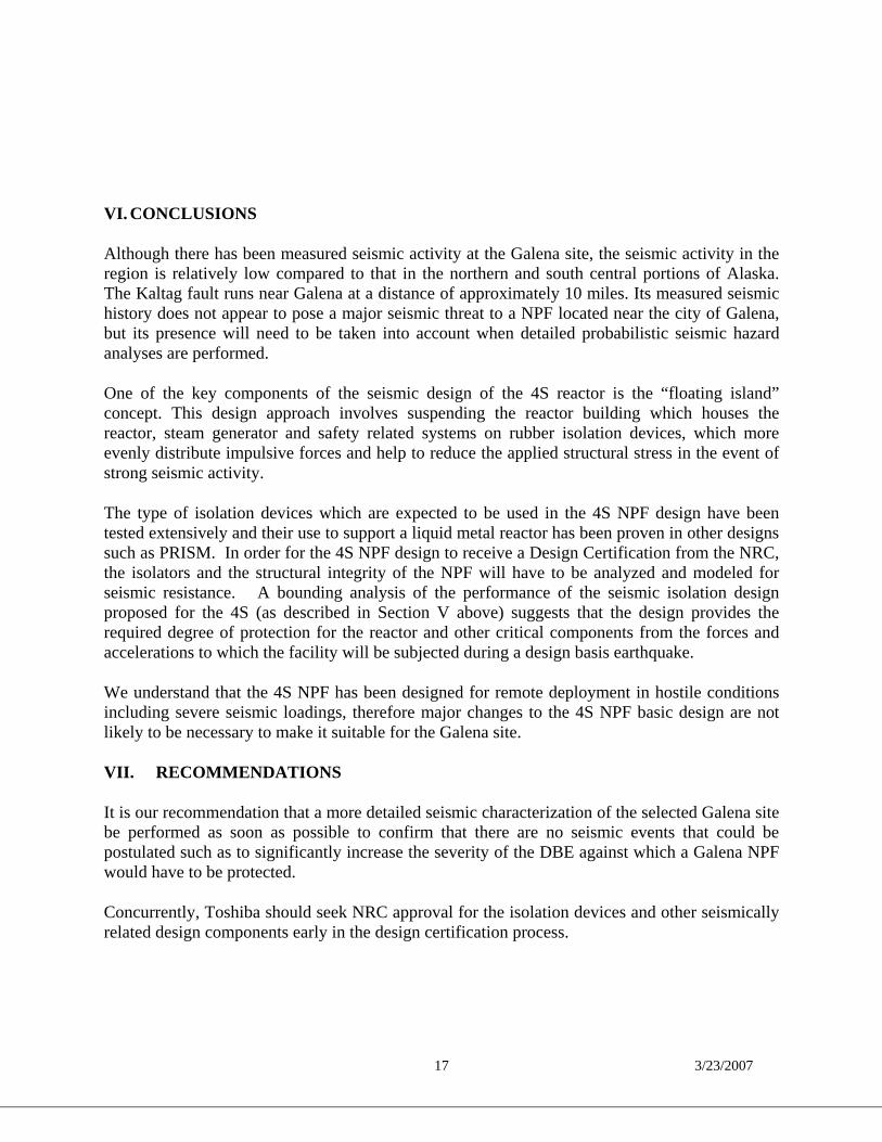
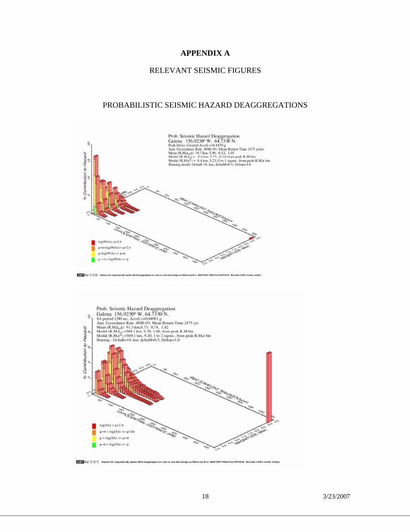
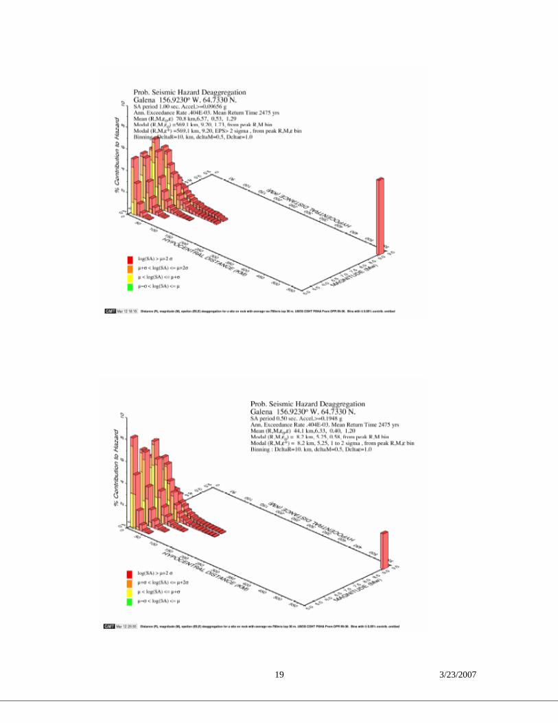
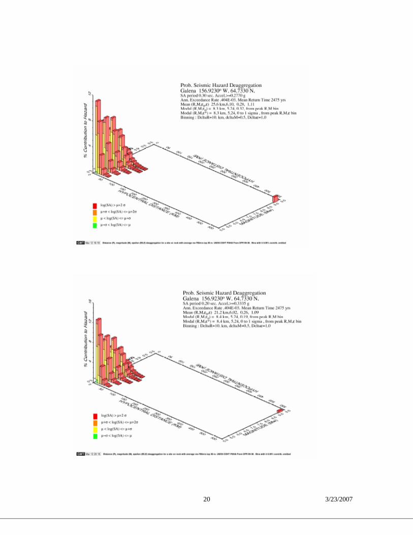
Seismic hazard maps for Alaska were released in 1999 by the United States Geological Survey (Wesson et.al, 1999). Probabilistic seismic hazard maps have been prepared for Alaska portraying ground motion values.8 Preparation of these maps followed the same general strategy as that followed for the U.S.G.S. seismic hazard maps of the contiguous United States, combining the hazard derived from spatially-smoothed historic seismicity with the hazard from fault-specific sources.9 The hazard is estimated for the recognized crustal faults of the Denali, Fairweather-Queen Charlotte and Castle Mountain fault systems based on available geologic slip rates. The hazard from other sources is estimated from spatially smoothed historic seismicity. Deaggregations of the hazard can be computed for various regions to reveal the dominant sources of the hazard at each location. For this analysis, deaggregation was accomplished for the area surrounding Galena. This is shown in the figures in Attachment A, for the 2% probability in 50 years hazard data. The bar graphs illustrate the contribution of earthquake sources to the overall hazard as a function of magnitude and distance from Galena.
From the data analyzed, the hazard can be seen to be bi-modal for Galena, meaning that the hazard is composed of the contribution of two sources: one, a cluster of sources derived from the smoothed seismicity surrounding the area; the other, the contribution from a M9.2 earthquake at
7Scenario Earthquakes for Korean Nuclear Power Plant Site Considering Active Faults (File: Korea Seismic k03-2.pdf) 8 The maps depict the peak ground acceleration and spectral amplitude (at periods of 0.2, 0.3 and 1.0 seconds) at
probabilities of exceedance of 2% and 10% in 50 years for the various locations. 9 Preparation of the Alaska maps presented particular challenges in characterizing the hazard from the Alaska-
Aleutian megathrust. In the maps of the contiguous United States, the rate of seismicity for recognized active faults was determined from slip rates estimated from geologic data. This approach is not appropriate for the megathrust, because it has been demonstrated that a significant fraction of the subduction occurs aseismically. The characteristic earthquake hypothesis, based on recurrence rates determined from geologic data, is appealing for the portion of the megathrust that ruptured in the 1964 Alaskan earthquake.

11 3/23/2007
a distance of ~570 km (the vicinity of the 1964 earthquake).10 The contribution from the M9.2 event is greatest for the low frequency (longer period) spectral accelerations, and the local events dominate the peak horizontal ground acceleration (PGA) and higher frequency spectral accelerations.
Figure 4.2 summarizes the PGA and the spectra acceleration (SA) for 2% probability in 50 years for the Galena site. As noted in the diagram, the peak response occurs at a frequency of approximately 6.6 Hz, at which the maximum horizontal acceleration is approximately .364 m/s2.
0 0.5 1 1.5 2 2.5 3 3.5 4 4.5 5 5.5 6 6.5 7 7.5 8 8.5 9 9.5 10 10.50
0.05
0.1
0.15
0.2
0.25
0.3
0.35
0.4Estimate Galena Response Spectra
Frequency (Hz)
Spec
tra H
oriz
onta
l Acc
eler
atio
n (m
/s2)
vg j
l r( )
gmax
vHzj r, Hmax,
gmax 0.36366:= (m/s2) Hmax 6.65:= (Hz)
Figure 4.2: PGA and SA for 2% in 50 years hazard data
D. Stochastic seismograms from the Hazard Deaggregation
From the estimated Galena peak horizontal ground acceleration and response spectra, it is possible to simulate the peak ground accelerations over the duration of an earthquake for each
10 An additional graph is included in Appendix A for the 1 sec Spectral Acceleration Geographic Deaggregation that
illustrates the bimodal source zones in a map view.

12 3/23/2007
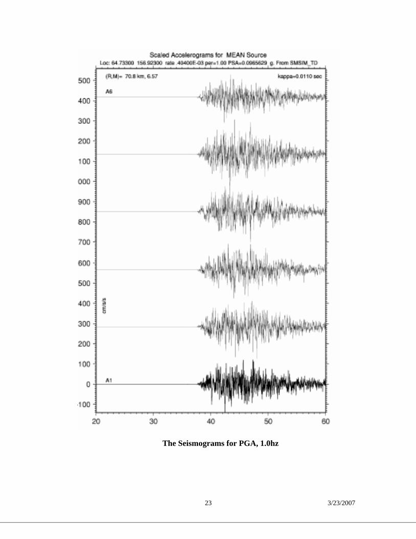
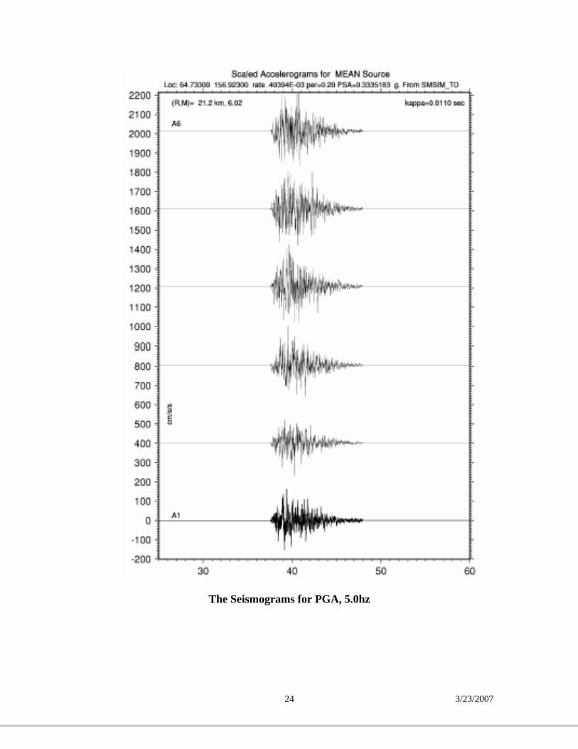
frequency of vibration. Those simulations are known as “seismograms”. Examples of seismograms, computed for a suite of representative sources, are presented in Appendix A.11
In the Modal case, the PGA seismograms and the 5.0hz Spectral Acceleration seismograms come from a local M5.24 source a distance of only 8.4 km away. In the Mean case, the seismograms for PGA, 1.0hz, and 5.0hz come from sources with (Distance-Magnitude) pairs of (19.7km, M5.96), (70.8km, M6.57), and (21.2km, M6.02) respectively. The seismograms present a set of sources that may be representative of regional events that could occur on the Kaltag Fault.
V. SEISMIC ISOLATION IN THE 4S NPF DESIGN
A. Basic Concept
In an earthquake, a fixed base structure is subjected to dynamic loads. These loadings can be amplified from resonant natural frequencies that are part of the structure’s characteristics. Because it is not uncommon for the natural frequency of a structure to coincide with the vibratory frequencies in a seismic event, structural failure can result if the structure is not properly designed to withstand seismic activity. The 4S nuclear island is a reinforced structure, designed to “float” above the reinforced base mat on seismic isolators. The utilization of rigid and elastic seismic design technology offers the 4S-NPF greater combined protection against potentially damaging seismic events.
The pressures encountered during normal operation in large light water reactors (LWRs) dictate the use of very heavy pipe and thick-walled reactor vessels. Because LWR structures are designed as massive reinforced concrete structures, they effectively stabilize the reactor and safety related systems in an earthquake. By contrast, although the piping and related components in the 4S-NPF are robust and double-walled for safety, the operating pressures and the related pipe thickness are relatively low when compared to high pressure steam piping, in LWRS, hence the 4S requires more advanced seismic protection. The 4S NPF design concept employs seismic isolators to support the nuclear island. The supported modules include the reactor vessel, the steam generator, and other safety-related systems. Seismic isolators introduce flexible elements between the reactor structure and the ground to uncouple the structure from the ground motion, especially in the horizontal direction. Isolation devices are designed to be most effective in the horizontal plane, because vertical seismic motions are of a lower magnitude. The resistance of the design to vertical seismic motions is therefore primarily handled by the rigid construction of the facility itself, along with the installation of seismically rated pipe supports and ducting. Seismic isolators are passive devices that do not depend on operator action, power supplies, electronic controls/devices, or complex mechanical systems to carry out their function, and simply require a periodic inspection program to remain effective.
11 The seismographs were generated with a computer program (SMSIM_TD) modified to run in the context of the
source deaggregation process. Distance-Magnitude pairs (R, M) was selected to represent either a Modal source (largest contribution), or a Mean source (an average contribution). Three sets of seismograms are presented for each of the Modal and Mean source representation. For each Modal and Mean source seismograms are computed and scaled for PGA, 1.0hz spectral acceleration, and 5.0hz spectral acceleration. Attenuation relations used for preparing the hazards maps are included in the calculation of the seismograms.
13 3/23/2007
Benefits of seismic isolation in advanced nuclear power plant applications include:12
• Standardization of the design regardless of seismic conditions, reducing capital costs; • Enhancement of safety and reliability; • Decoupling of the reactor design and development, which is global in nature, from the
balance of plant (BOP) design and licensing, which is regional in nature; and • Assurance that the structural responses in the horizontal direction are limited to less than
~ 1 Hz, therefore virtually decoupling the structure from horizontal ground motion.13
B. Seismic Isolation in the 4S Design
Seismic isolation devices are typically installed between the superstructure and the base structure of a building or structure in order to reduce the seismic forces acting on the superstructure. Since the seismic isolation devices are installed between the superstructure and the base structure, they also function to support the superstructure. Therefore, the isolation devices are treated as indirect supporting structures which have the function of supporting the superstructure and controlling and/or suppressing the seismic response of equipment and piping installed in the superstructure. In the 4S design, seismic isolators are installed between the reactor building (superstructure) and the base structure to uncouple the reactor building from the ground motion so that the potentially damaging horizontal ground motions of an earthquake are not transmitted to the reactor building structure, systems, and components. In the 4S design, all safety related equipment is housed in the Reactor Building.
Figure 5.1 is a simplified schematic cross-section view of the 4S NPF. As seen in the figure, the 4S reactor building houses and supports the reactor vessel, the containment guard vessel, the 12 US Base Isolation Design for Civil Components and Civil Structures (File: fft_1998.pdf) 13 The use of seismic isolation devices is not new. The Advanced Liquid Metal Reactor (ALMR) sponsored by the
U.S. Department of Energy (DOE) has adopted seismic isolation devices into its design. This helps to simplify the design, enhance safety margins, and support the development of a standardized design for the majority of the available U.S. reactor sites. The nuclear island is being designed for a safe shutdown earthquake (SSE) with a maximum horizontal and vertical acceleration of 0.5g. Detailed seismic analyses of the ALMR have been performed and the results reported elsewhere by Tajirian and Patel (1993). The ALMR isolated structural configuration consists of a stiff rectangular steel-concrete box structure, which supports the reactor vessel, the containment dome, and the reactor vessel auxiliary cooling system stacks. The total isolated weight is about 23,000 tons and is supported on 66 high damping rubber bearings. The horizontal isolation frequency of this design is 0.7 Hz, and the vertical frequency is greater than 20 Hz.
A qualification program for the ALMR seismic isolation system was established to demonstrate that all seismic
design and safety requirements are met. The essential categories are bearing tests, both reduced-scale and full-size, bearing environmental tests, and seismic isolation system tests. To date a large number of bearing tests have been performed and the results reported elsewhere by Tajirian et al. (1990), Clark et al. (1995).
Another DOE-sponsored project, the Sodium Advanced Fast Reactor (SAFR) houses the reactor assembly module in a standardized shop-fabricated unit housed in a building constructed above grade with plan dimensions of 38 m by 25 m. The building, which weighs 31,000 tons, is supported on 100 seismic isolators. What makes the isolation system for SAFR unique is that it provides vertical as well as horizontal isolation. The design horizontal frequency is 0.5 Hz and the vertical frequency is 3 Hz. This is achieved by using bearings with thicker rubber layers than usual, which are flexible vertically as well as horizontally. The bearing diameter is 107 cm, the total height is 41 cm, and consists of three layers of rubber each 10.2 cm thick with a shape factor of only 2.3. Reduced scale bearings were extensively tested to validate the concept of low shape factor bearings, Aiken et al. (1989).

14 3/23/2007
base mat, the steam generator, and auxiliary equipment cells. Composite rubber/steel/lead core seismic isolation devices are used to limit horizontal seismic input to the reactor vessel, guard vessel, auxiliary equipment and steam generator. Figure 5.2 shows the seismic isolator arrangement in the base floor of the Reactor Building.
Figure 5.1: Representation of Seismic Isolator Arrangement in Cross-Section View of
Reactor Building
Figure 5.2: Representation of Seismic Isolator Arrangement in the Base Floor of the Reactor Building
15 3/23/2007
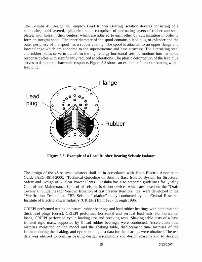
The Toshiba 4S Design will employ Lead Rubber Bearing isolation devices consisting of a composite, multi-layered, cylindrical spool comprised of alternating layers of rubber and steel plates, with holes in their centers, which are adhered to each other by vulcanization in order to form an integral spool. The inner diameter of the spool contains a lead plug or cylinder and the outer periphery of the spool has a rubber coating. The spool is attached to an upper flange and lower flange which are anchored to the superstructure and base structure. The alternating steel and rubber plates serve to transform the high energy horizontal seismic motions into harmonic response cycles with significantly reduced accelerations. The plastic deformation of the lead plug serves to dampen the harmonic response. Figure 5.3 shows an example of a rubber bearing with a lead plug.
Figure 5.3: Example of a Lead Rubber Bearing Seismic Isolator
The design of the 4S seismic isolators shall be in accordance with Japan Electric Association Guide JAEG 4614-2000, “Technical Guideline on Seismic Base Isolated System for Structural Safety and Design of Nuclear Power Plants.” Toshiba has also prepared guidelines for Quality Control and Maintenance Control of seismic isolation devices which are based on the “Draft Technical Guidelines for Seismic Isolation of fast breeder Reactors” that were developed in the “Verification Test of the FBR Seismic Isolation” study conducted by the Central Research Institute of Electric Power Industry (CRIEPI) from 1987 through 1996.
CRIEPI performed testing on natural rubber bearings and lead rubber bearings with both thin and thick lead plugs (cores). CRIEPI performed horizontal and vertical load tests. For horizontal loads, CRIEPI performed cyclic loading test and breaking tests. Shaking table tests of a base isolated rigid mass, supported by 8 lead rubber bearings, were conducted. Acceleration time histories measured on the model and the shaking table, displacement time histories of the isolators during the shaking, and cyclic loading test data for the bearings were obtained. The test data was utilized to confirm bearing design assumptions and design margins and to develop
Rubber
Flange
Lead plug
16 3/23/2007
numerical simulations for analyzing new designs and sizes of bearings.18 In addition, a seismic isolator qualification test program was established for the PRISM Reactor using High Damping Rubber Bearings. These bearings are in the same category as the lead rubber bearings in the fact that they provide a damping function via the type of elastomeric rubber utilized versus the lead plug. The results of the first series of tests on the ½ scale high damping rubber bearings are summarized in NUREG1368. One of the bearings was loaded to the maximum capacity of the test machine (4000 kips) to determine its ultimate load carrying capability. The bearing sustained no apparent damage to either the high damping rubber plates or steel plates. Also, 2 bearings were stacked and a ramped load was applied to determine the buckling load. The buckling load was 28 times greater than the design load. 19
An extensive series of experimental tests to identify the mechanical characteristics of three types of seismic isolation bearings (2 types of high damping bearings and one type of lead rubber bearing) were performed on a large scale, reinforced concrete model of a three story building in Sedai, Japan. Cyclic horizontal displacement tests with varying shear displacement amplitudes, axial loads, and loading frequencies were performed on all three bearing types. Ultimate level tests were also performed. All of the bearings performed well in the large range of tests conducted.20 18 www.iaea.or.at, Summary – Coordinated Research Project on the Implementation of Base Isolation for Nuclear Structures under the auspices of the TWGFR. 19NUREG-1368, Pre-application Safety Evaluation Report for the Power Reactor Innovative Small Module
(PRISM) Liquid Metal Reactor, published February 1994, USNRC.
20 Proceedings, Tenth World Conference On Earthquake Engineering, Madrid, Spain, July 1992, “Experimental Studies of the Mechanical Characteristics of Three Types of Seismic Isolation Bearings,” Ian D. Aiken, James M. Kelly, Peter W. Clark – Earthquake Engineering Research Center, University of California at Berkeley, USA and Kazou Tamura, Masaru Kikuchi, Tetsuji Itoh – Ohsaki Research Institute, Shimizu Corporation, Tokyo, Japan.
17 3/23/2007
VI. CONCLUSIONS
Although there has been measured seismic activity at the Galena site, the seismic activity in the region is relatively low compared to that in the northern and south central portions of Alaska. The Kaltag fault runs near Galena at a distance of approximately 10 miles. Its measured seismic history does not appear to pose a major seismic threat to a NPF located near the city of Galena, but its presence will need to be taken into account when detailed probabilistic seismic hazard analyses are performed.
One of the key components of the seismic design of the 4S reactor is the “floating island” concept. This design approach involves suspending the reactor building which houses the reactor, steam generator and safety related systems on rubber isolation devices, which more evenly distribute impulsive forces and help to reduce the applied structural stress in the event of strong seismic activity.
The type of isolation devices which are expected to be used in the 4S NPF design have been tested extensively and their use to support a liquid metal reactor has been proven in other designs such as PRISM. In order for the 4S NPF design to receive a Design Certification from the NRC, the isolators and the structural integrity of the NPF will have to be analyzed and modeled for seismic resistance. A bounding analysis of the performance of the seismic isolation design proposed for the 4S (as described in Section V above) suggests that the design provides the required degree of protection for the reactor and other critical components from the forces and accelerations to which the facility will be subjected during a design basis earthquake.
We understand that the 4S NPF has been designed for remote deployment in hostile conditions including severe seismic loadings, therefore major changes to the 4S NPF basic design are not likely to be necessary to make it suitable for the Galena site.
VII. RECOMMENDATIONS
It is our recommendation that a more detailed seismic characterization of the selected Galena site be performed as soon as possible to confirm that there are no seismic events that could be postulated such as to significantly increase the severity of the DBE against which a Galena NPF would have to be protected.
Concurrently, Toshiba should seek NRC approval for the isolation devices and other seismically related design components early in the design certification process.
18 3/23/2007
APPENDIX A
RELEVANT SEISMIC FIGURES
PROBABILISTIC SEISMIC HAZARD DEAGGREGATIONS
19 3/23/2007
20 3/23/2007

21 3/23/2007

22 3/23/2007
SCALED ACCELEROGRAMS
Spectral Acceleration seismogram which represents a M9.2 source 570 km away illustrating the dominance of the 1964 type event at longer periods
23 3/23/2007
The Seismograms for PGA, 1.0hz
24 3/23/2007
The Seismograms for PGA, 5.0hz