Embed Size (px)
Citation preview

Cisco MWR 1941-DC Mobile Wireless E78-15827-06B0
C H A P T E R 1
Overview of the Cisco MWR 1941-DC RouterThe MWR 1941-DC Mobile Wireless Edge Router is a networking platform optimized for use in mobile wireless networks; specifically designed to be used at the cell site edge as a part of an IP Radio Access Network (IP-RAN) or Cell Site Data Communications Network (DCN).
The MWR 1941-DC router offers high performance at a low cost while meeting the critical requirements for deployment in cell sites, including small size, high availability, and DC input power flexibility.
This chapter includes the following sections:
• Primary Uses of the MWR 1941-DC Router, page 1-1
• Hardware Features, page 1-4
• Fixed Interfaces, page 1-5
• Voice/WAN Interface Cards, page 1-5
• Cisco Network Modules, page 1-7
• Compact Flash, page 1-7
• Overview of MWR 1941-DC Power Supply, page 1-8
• Environmental Monitoring Temperature Sensor, page 1-9
• System Specifications, page 1-9
• Cisco MWR 1941-DC Router Interface Numbering, page 1-9
• Regulatory Compliance, page 1-11
Primary Uses of the MWR 1941-DC RouterThe MWR 1941-DC router is designed to be used at a cell site as part of an IP-RAN or Cell Site DCN solution.
1-1dge Router Hardware Installation Guide

Chapter 1 Overview of the Cisco MWR 1941-DC RouterPrimary Uses of the MWR 1941-DC Router
IP-RAN Solution Implementation
In an IP RAN solution, the MWR 1941-DC extends IP connectivity to the cell site and Base Transceiver Station (BTS). Through a FastEthernet interface to the BTS, provides bandwidth-efficient IP transport of voice and data bearer traffic, as well as maintenance, control, and signalling traffic, over the leased line backhaul network between the BTS and leased line termination and aggregation node via compression (cRTP/cUDP) and packet multiplexing (PPPmux and MLPPP).
Figure 1-1 shows the placement of and connections for the MWR 1941-DC in an IP-RAN solution.
Figure 1-1 MWR 1941-DC in an IP-RAN Solution
In the IP-RAN solution, the BTS site consists of a pair of MWR 1941-DC routers. The pair of MWR 1941-DC routers provides for an active and standby router for redundancy. A failure of the active MWR 1941-DC causes the standby router to take over as the active router for the BTS site.
Each pair of MWR 1941-DC routers at the BTS site is identical in hardware configuration. They connect to each other through the BTS via the Fast Ethernet interfaces. The individual backhaul links to an MWR 1941-DC router are cabled from a single T1/E1 termination block in the BTS, connecting to both the active and standby routers utilizing a “Y” cable. The redundancy design to control the active/standby transitions of the router pair leverages HSRP to control the relays on the VWIC-2MFT-T1-DIR (or VWIC-2MFT-E1-DIR) in each router to ensure that the relays on the active router are closed and the relays on the standby router are open to avoid double termination of the T1 (or E1).
Cell Site DCN Solution Implementation
With Cisco IOS Release 12.2(15)MC1a and later, the MWR 1941-DC can be used to extend the mobile operators data communications network (DCN) to the cell site, providing the ability to remotely manage radio and ancillary cell site equipment from the operations center.
A Cell Site DCN minimizes the need to dispatch technicians for every problem that might occur by providing the ability to remotely perform the following types of tasks:
• troubleshooting
• diagnosis
• repairs
• control
• upgrades
• routine maintenance of the cell site devices
A Cell Site DCN also provides IP connectivity to the cell site, enabling IP-related applications that facilitate operation support (for example, web camera for site surveillance, IP telephone for voice connectivity, and the LAN extension to the cell site to provide access to network applications and data, and access to the Internet and/or intranet).
Active
pBTS
MWR 1900 IP BTS router pair
100BaseT
T1/E1 backhaul link toIP RAN aggregation node
Standby
6582
7
1-2Cisco MWR 1941-DC Mobile Wireless Edge Router Hardware Installation Guide
78-15827-06B0
Chapter 1 Overview of the Cisco MWR 1941-DC RouterPrimary Uses of the MWR 1941-DC Router
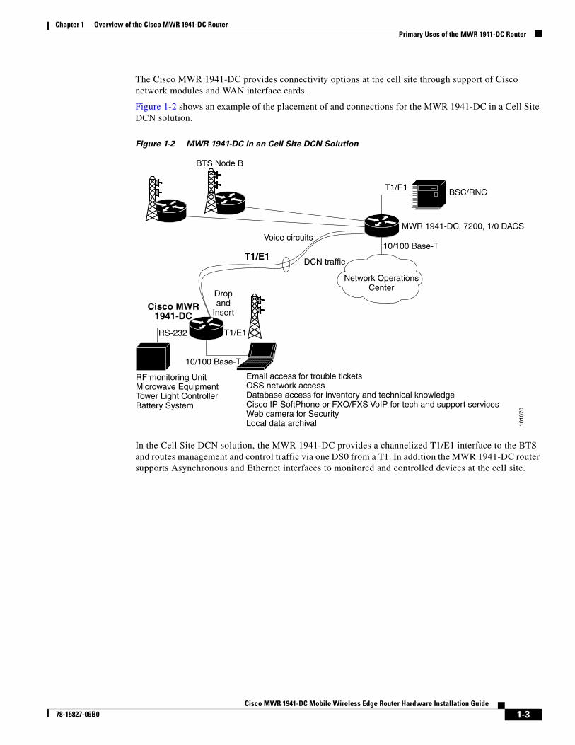
The Cisco MWR 1941-DC provides connectivity options at the cell site through support of Cisco network modules and WAN interface cards.
Figure 1-2 shows an example of the placement of and connections for the MWR 1941-DC in a Cell Site DCN solution.
Figure 1-2 MWR 1941-DC in an Cell Site DCN Solution
In the Cell Site DCN solution, the MWR 1941-DC provides a channelized T1/E1 interface to the BTS and routes management and control traffic via one DS0 from a T1. In addition the MWR 1941-DC router supports Asynchronous and Ethernet interfaces to monitored and controlled devices at the cell site.
Network OperationsCenter
BTS Node B
DCN traffic
10/100 Base-T
T1/E1
MWR 1941-DC, 7200, 1/0 DACS
BSC/RNC
Voice circuits
T1/E1
Cisco MWR1941-DC
Dropand
Insert
T1/E1
10/100 Base-T
RF monitoring UnitMicrowave EquipmentTower Light ControllerBattery System
Email access for trouble ticketsOSS network accessDatabase access for inventory and technical knowledgeCisco IP SoftPhone or FXO/FXS VoIP for tech and support servicesWeb camera for SecurityLocal data archival
RS-232
1010
70
1-3Cisco MWR 1941-DC Mobile Wireless Edge Router Hardware Installation Guide
78-15827-06B0

Chapter 1 Overview of the Cisco MWR 1941-DC RouterHardware Features
Hardware FeaturesFigure 1-3 shows the front of the router. Figure 1-4 shows the back of the router.
The configuration in this graphic is as follows:
• A VWIC is installed in two of the three WIC slots
• A 4-port asynchronous/synchronous serial network module is installed in the network module slot (Cell Site DCN implementation).
Figure 1-3 Front Panel of the Cisco MWR 1941-DC Router
Figure 1-4 Back Panel of the Cisco MWR 1941-DC Router
The Cisco MWR 1941-DC router includes the following features:
• Two DIMM-168 SDRAM (4 banks) sockets
• SysAD bus speed and SDRAM local bus speed is 80Mhz
• External Compact Flash (CF)
9871
6
SEE MANUAL BEFORE INSTALLATIONDSU56K
SEE MANUAL BEFORE INSTALLATIONDSU56K
CONSOLEAUXILIARY
CN/LP
2
1
0
3 RXC RXD TXC TXDCN/LP RXC RXD TXC TXD
CN/LP RXC RXD TXC TXDCN/LP RXC RXD TXC TXD EN
SERIALA/S
Serial 0/3Serial 0/2
Serial 0/1Serial 0/0
Serial 1/3Serial 1/2
Serial 1/1
Serial 1/0FE1
FE0Console
portAuxiliary
port
Powerconnector
Fan
Rack mount bracket(both sides)
Groundingnut/screw
6578
4
1-4Cisco MWR 1941-DC Mobile Wireless Edge Router Hardware Installation Guide
78-15827-06B0

Chapter 1 Overview of the Cisco MWR 1941-DC RouterFixed Interfaces
• Two fixed LAN 10/100 Base-T Ethernet Ports
• Three WIC/VIC expansion slots (third slot supported in Cell Site implementation only)
• One network module slot (Cell Site DCN implementation only)
• Redundancy support via a two T1/E1 WIC capable of port switching ON/OFF via relays (IP-RAN implementation only)
• Console RS-232 port
• Auxiliary Serial Port with hardware flow control
• Front (connector side) to rear airflow using four 40mm, 10 CFM exhaust fans
• + 27/-48 VDC (+/- 20 to 60 VDC supply tolerance) universal power supply
• Three green chassis LEDs for Power (PS is operational), System Ready (software is up and running), and Activity (interrupts/packet transfers running)
Fixed InterfacesThe MWR 1941-DC router has two fixed LAN ports offering 10/100 Base-T Ethernet attachment. The ports are fully compliant with the IEEE 802.3 and 802.3U standards and integrate the media access control (MAC) functions and a dual-speed MII interface. Both ports can operate in half- or full-duplex mode and can run independently of one another. For each FE interface, there are two green LEDs, one for Link Integrity and one for Link Activity.
Voice/WAN Interface CardsThe Cisco MWR 1941-DC router supports the following Voice/WAN interface cards (VWICs):
• 2-port T1/Fractional T1 Drop and Insert Multiflex Trunk Interface Card: VWIC-2MFT-T1-DIR(=)
• 2-port E1/Fractional E1 Drop and Insert Multiflex Trunk Interface Card: VWIC-2MFT-E1-DIR(=)
• 2-port Asynchronous/Synchronous WAN Interface Card: WIC-2A/S(=)
Note The WIC-2A/S is supported by the Cell Site DCN implementation only with Cisco IOS Release 12.2(15)MC1a and later.
IVWIC-2MFT-T1/E1-DIR
The Cisco VWIC-2MFT-T1-DIR and VWIC-2MFT-E1-DIR VWICs support data applications on the Cisco MWR 1941-DC Mobile Wireless Edge Router for T1/E1 networks. These cards are dual-port, T1/Fractional T1 or E1/Fractional E1, Drop and Insert Multiplexers with integrated T1 CSU/DSUs or E1 DSUs. The T1 version supports framed and unframed traffic, and the E1 version supports framed traffic and unframed traffic that conforms to the ITU-T G.703 standard for full 2.048 Mbps bandwidth.
The Drop and Insert multiplexer diverts (drops) streams of an aggregate Time Division Multiplexed (TDM) traffic stream, and introduces (inserts) different streams for transmission in the time slots that were previously occupied by the dropped streams. Each VWIC supports a limited channelized capability where the T1 or E1 can be flexibly split into two fractional channel groups, one on each port or two on one port. The switching operation can be maintained through router restarts and reloads of Cisco IOS software.
1-5Cisco MWR 1941-DC Mobile Wireless Edge Router Hardware Installation Guide
78-15827-06B0

Chapter 1 Overview of the Cisco MWR 1941-DC RouterVoice/WAN Interface Cards
Each card also features protection switch solid state relays on the line interfaces, which together with redundancy logic and relay control added to the base Cisco IOS feature set on the MWR 1941-DC, provides T1/E1 Protection Switching between redundant routers.
The MWR 1941-DC router provides three WAN interface slots.
Additional information is contained in separate publications.
• For information on the VWIC-2MFT-T1/E1-DIR VWICs, see the publication VWIC-2MFT-T1DIR, VWIC-2MFT-E1DIR Installation Instructions.
• For software configuration information, see the publication Cisco MWR 1941-DC Software Configuration Guide.
These manuals are on Cisco.com. See “Obtaining Documentation” section on page xi for more information.
WIC-2A/S
The dual-serial port WAN Interface Card (WIC-2A/S) provides higher levels of serial port density for a single WIC on the MWR 1941-DC router in a Cell Site DCN implementation. The low serial speed WIC-2A/S supports up to 128 Kbps synchronous or 115.2 Kbps asynchronous serial links. Each port on a WIC is a different physical interface and can support different protocols such as Point-to-Point Protocol (PPP) or Frame Relay and Data Terminal Equipment/Data Communications Equipment (DTE/DCE). This WIC supports mixed asynchronous and synchronous operation on a single card as well.
These dual-serial port WICs feature Cisco's new, compact, Smart Serial connectors to support a wide variety of electrical interfaces when used with the appropriate transition cable. This includes: V.35, RS-232, RS-449, RS-530, RS-530A in male and female versions for both DTE and DCE devices. This feature provides easy configuration and reconfiguration as network requirements change, without the need of purchasing a different serial interface card.
The WIC-2A/S provides two serial ports using the Smart Serial connector.
• Asynchronous support with a maximum speed of 115.2 Kbps, and a minimum of 600 bps. If you need to run at speeds lower than 600 bps, use the AUX port instead.
• Synchronous support with a maximum speed of 128 Kbps.
Additional information is contained in separate publications.
• For instructions on installing the WIC-2A/S and detailed information about the WIC-2A/S, see the Cisco Interface Cards Installation Guide.
• For software configuration information, see the publication Cisco MWR 1941-DC Software Configuration Guide.
These manuals are on Cisco.com. See “Obtaining Documentation” section on page xi for more information.
1-6Cisco MWR 1941-DC Mobile Wireless Edge Router Hardware Installation Guide
78-15827-06B0

Chapter 1 Overview of the Cisco MWR 1941-DC RouterCisco Network Modules
Cisco Network ModulesFor implementation in a Cell Site DCN, with Cisco IOS Release 12.2(15)MC1a, the Cisco MWR 1941-DC router also supports the following Cisco network modules:
• Alarm Interface Card—NM-AIC-64(=)
• 16-port Ethernet Switch—NM-16ESW(=)
Note When using the NM-16ESW with the MWR 1941-DC router, shielded cables are required and IP phone inline power is not supported.
• Asynchronous
– 16-port Asynchronous Serial—NM-16A(=)
– 4-port Asynchronous/Synchronous Serial: NM-4A/S(=)
– 8-port Asynchronous/Synchronous Serial: NM-8A/S(=)
• 1-port T3/E3: NM-1T3/E3(=)
Note When used with the MWR 1941-DC router, the NM-1T3/E3 supports line rate throughput for traffic with packet sizes of 1500 bytes. For traffic with smaller packet sizes, degradation in throughput will be seen.
Additional information is contained in separate publications.
• For instructions on installing these network modules and details on each of these network modules and their interfaces, see the Cisco Network Modules Hardware Installation Guide.
• For software configuration information, see the publication Cisco MWR 1941-DC Software Configuration Guide.
These manuals are on Cisco.com. See “Obtaining Documentation” section on page xi for more information.
Compact FlashOne external Compact Flash (CF) device is used on the MWR 1941-DC router. The MWR 1941-DC Compact Flash memory cards is available in 32 MB and 64 MB of memory. This device is configured in memory mapped mode (PCMCIA) to allow for hot insertion. This device is required for the MWR 1941-DC router to function because the IOS image and troubleshooting logs reside on this device. For information about replacing or upgrading the CF, see the “Replacing or Upgrading the CF” section on page 3-13.
1-7Cisco MWR 1941-DC Mobile Wireless Edge Router Hardware Installation Guide
78-15827-06B0

Chapter 1 Overview of the Cisco MWR 1941-DC RouterOverview of MWR 1941-DC Power Supply
Overview of MWR 1941-DC Power SupplyThe MWR 1941-DC router is equipped with a +27/-48 VDC universal power supply.
Table 1-1 lists DC power supply specifications of the Cisco MWR 1941-DC router.
The Cisco MWR 1941-DC router uses a small, three-wire connector for input to the power supply. The connector ships in the accessory kit and is Phoenix Contact part number 1756272.
With the connector installed in the chassis, the pins from top to bottom are 1, 2 and 3. Table 1-2 and Table 1-3 list the pinout configurations for the connector based on power source.
Table 1-1 Cisco MWR 1941-DC Power Supply Specifications
Specification +27/-48 VDC
Input voltage, DC power supply
Maximum input current
Note If the input voltage drops below 18.5 VCD, the router will go into shut down mode.
+27/-48 VDC (±20 to 60 VDC supply tolerance) universal power supply
3.5A
Wire gauge for DC-input power connections
18 AWG
Power Dissipation 70 W (maximum) 35 W (typical)
Table 1-2 Power Supply Connectors Pinout—+27 VDC Application
PIN +27 VDC Power Source
1 +27 VDC
2 Ground
3 RTN
Table 1-3 Power Supply Connectors Pinout—-48 VDC Application
PIN -48 VDC Power Source
1 RTN
2 Ground
3 -48 VDC
1-8Cisco MWR 1941-DC Mobile Wireless Edge Router Hardware Installation Guide
78-15827-06B0

Chapter 1 Overview of the Cisco MWR 1941-DC RouterEnvironmental Monitoring Temperature Sensor
Environmental Monitoring Temperature SensorThe MWR 1941-DC router has a temperature sensor to detect over-temperature conditions inside the chassis. The over-temperature detection trips at 75°C +/- 5%. This condition is reported to the processor as an interrupt and software then takes action on this interrupt to generate the appropriate alarming. If the router reaches a temperature of 90°C, the power supply will cycle to prevent the box from exceeding that temperature in a powered up state.
System SpecificationsTable 1-4 lists the Cisco MWR 1941-DC router system specifications.
Cisco MWR 1941-DC Router Interface NumberingEach network interface on a Cisco MWR 1941-DC router is identified by a slot number and a port number.
Figure 1-5 shows an example of interface numbering on a Cisco MWR 1941-DC router with the following configuration for a Cell Site DCN implementation:
• A VWIC in two of the three VWIC slots
• A 4-port asynchronous/synchronous serial network module in slot 1
• Two built-in Fast Ethernet interfaces
Table 1-4 Cisco MWR 1941-DC Router System Specifications
Description Specification
Dimensions (H x W x D) 1.72 x 17.5 x 12.5 in. (4.368 x 44.45 x 31.75 cm) 1RU/19.00 Rack Mount
Weight 10.5 lb (4.77 kg)
Console and Auxiliary ports RJ-45 connector
Operating Temperature 32 to 122°F (0 to + 50°C)1
1. When two or less VWIC-2MFT-T1/E1-DIRs are installed in the Cisco MWR 1941-DC router, an operating temperature range of 14 to 131°F (-10 to +55°C) is supported.
Non-Operational Temperature -40 to 185°F (-40 to 85°C)
Operating Humidity 5 to 90% RH (non-condensing)
Operating Altitude +3000m @ 113°F (45°C)
Operating Vibration 0.41 Grms, 3 to 500 Hz/2 hours per axisGR-63-CORE earthquake resistance, Zone 4, shelf-level
Non-Operational Vibration 1.12 Grms, 3 to 500 Hz/30 minutes per axis
Operating Acoustics < 60 dBa
1-9Cisco MWR 1941-DC Mobile Wireless Edge Router Hardware Installation Guide
78-15827-06B0

Chapter 1 Overview of the Cisco MWR 1941-DC RouterCisco MWR 1941-DC Router Interface Numbering
Figure 1-5 Cisco MWR 1941-DC Router Port Numbers
Slot and Port Numbering
Note The IP-RAN implementation does not support the third VWIC or network module slot.
The Cisco MWR 1941-DC router chassis contains the following LAN and WAN interface types:
• Two built-in Fast Ethernet LAN interfaces
• Three slots in which you can install Voice/WAN interface cards (VWICs)
• One slot in which you can install a network module
The slot numbers are as follows:
• 0 for all built-in interfaces
• 0 for all built-in VWIC slots
• 1 for the network module slot
The numbering format is:
Interface type Slot number/Interface number
Interface (port) numbers begin at 0 for each interface type, and continue from right to left.
• The two built-in Ethernet 10/100 interfaces are Fast Ethernet 0/0 and Fast Ethernet 0/1.
• The slot number for all VWIC interfaces in the built-in VWIC slot is always 0. (The W0, W1, and W2 slot designations are for physical slot identification only.) Interfaces in the VWICs are numbered from right to left, starting with 0/0 for each interface type, regardless of the physical VWIC slot in which the VWICs are installed.
9871
6
SEE MANUAL BEFORE INSTALLATIONDSU56K
SEE MANUAL BEFORE INSTALLATIONDSU56K
CONSOLEAUXILIARY
CN/LP
2
1
0
3 RXC RXD TXC TXDCN/LP RXC RXD TXC TXD
CN/LP RXC RXD TXC TXDCN/LP RXC RXD TXC TXD EN
SERIALA/S
Serial 0/3Serial 0/2
Serial 0/1Serial 0/0
Serial 1/3Serial 1/2
Serial 1/1
Serial 1/0FE1
FE0Console
portAuxiliary
port
1-10Cisco MWR 1941-DC Mobile Wireless Edge Router Hardware Installation Guide
78-15827-06B0

Chapter 1 Overview of the Cisco MWR 1941-DC RouterRegulatory Compliance
For example, if you have a VWIC in two of the VWIC slots (W0 and W1), then the interfaces are:
– Serial 0/0 and Serial 0/1 in physical slot W0
– Serial 0/2 and Serial 0/3 in physical slot W1
However, if you install a VWIC in physical slot W1 (leaving slot W0 empty), the interfaces in slot W1 are Serial 0/0 and Serial 0/1. If you then add a VWIC to slot W0, the interface numbering will shift. The configuration that you created for interfaces Serial 0/0 and Serial 0/1 will now be applied to the VWIC in slot W0 and you will need to create a new configuration for the interfaces that you previously configured on W1 (which will now be Serial 0/2 and Serial 0/3).
• The slot number of WIC/VWIC interfaces installed in slot 1 using a WAN network module is always 1 and the interfaces are always numbered from the right to left.
• The slot number for all network module interfaces is always 1 and the interfaces are always numbered from right to left starting with 1/0.
Regulatory ComplianceFor regulatory compliance and safety information, see the Regulatory Compliance and Safety Information for the Cisco MWR 1941-DC Mobile Wireless Edge Router document. This document shipped with your router and is also available on Cisco.com. See “Obtaining Documentation” section on page xi for more information.
1-11Cisco MWR 1941-DC Mobile Wireless Edge Router Hardware Installation Guide
78-15827-06B0

Chapter 1 Overview of the Cisco MWR 1941-DC RouterRegulatory Compliance
1-12Cisco MWR 1941-DC Mobile Wireless Edge Router Hardware Installation Guide
78-15827-06B0