Embed Size (px)
Citation preview

Overview of Tekeze hydroelectric power plant General The Ethiopian Electric power corporation constructed the Tekeze hydro electric power plant as part of the Country’s general development plan with the aim of expanding the electric power generation capacity. The power plant was designed to accommodate four 75MW units, with three of these to be installed during the initial phase and the fourth to be added at some time in the future. However, during the early stages of construction, it was decided to add the 4th unit, bringing the total capacity to 4 x 75 MW. With anticipated annual firm energy production of 981GWhr, the plant will play an important role in the development of the Ethiopian economy.
Tekeze hydroelectric power plant location
A feasibility study carried out in 1997, investigated 6 potential dam sites and the one , designated Tk5, was selected, at co-ordinates 13° 21’ North and 38° 45’ East, approximately 80 km west of the town of Mekele. The dam is located in a steep, narrow gorge, which the river has carved through the surrounding plateau during the course of many millions of years. The powerhouse is located in an underground cavern, excavated in the rock on the downstream side of the dam, adjacent to the right bank of the river at an altitude of 970m above mean sea level, whereas the crest of the dam is 1145m above sea level and the substation on the right bank plateau is at approximately 1300 masl.
TK5 Dam site location

The Tekeze River, which forms the boundary between the Regions of Tigray and Amhara, flows northwards and is a major tributary of the Atbara River, which is itself a tributary of the Nile. Previously undeveloped, the Tekeze is now generating hydroelectric power and makes a significant contribution Ethiopia’s economy. In addition, the reservoir that has been formed upstream of the dam has potential for the development of commercial fisheries and tourism, while, downstream, regulation of the river has potential benefits for the development of irrigation schemes.
Tekeze 3D model
The development of Tekeze hydroelectric plant involved the construction of a 188m high, mass concrete double curvature arch dam, spanning 450m across a 350m deep natural gorge, two river diversion tunnels, an underground powerhouse, water conveyance tunnels and outlet works, a variety of hydromechanical and electromechanical equipment, substation and a 105 km long transmission line to link with the Ethiopian national grid at Mekele. In addition, a residential camp was constructed, together with access roads, water supply system and other necessary infrastructure.
Procurement
Realization of the Tekeze Hydroelectric Power Project required the awarding of seven contracts. The selection of the contractors and the consultant was by International Competitive Bidding (ICB). During the tendering periods of the various contracts, 20 contractors from 8 countries participated and those with lowest tender prices, with sufficient experience and sound financial capacity were selected.
• The Consultancy Services Contract, encompassing design review and construction supervision of all the civil and electromechanical works was awarded to a joint venture of Harza Engineering Company Inc of the USA (now known as MWH – Montgomery Watson Harza) and Energoproject-Hidroinzenjering of Serbia.
• The Lot 1A Contract for the design and construction of a new 35km access road to the site was awarded to Berta Construction Company, a local Ethiopian company. This

work was carried out under an advance works contract and was completed before the main construction contract commenced.
• The Lot 1B/2/3 Contract, encompassing the supply, erection and commissioning of the Main Civil works was awarded to the CWGS Joint Venture, comprising three companies; CWHEC (now Sinohydro) and CGGC of China and Sur Construction Company of Ethiopia. This Contract included the construction of access roads and tunnels, two river diversion tunnels, the dam, powerhouse, waterway tunnels, outlet works, Employers camp and the design, supply installation of mechanical and electrical equipment for the dam outlets (4x low level outlets, 2x Diversion Bonneted gates), Intake Gate cranes and Tunnel steel liners etc.
• The Lot 4/5 Contract, encompassing design, manufacture, supply, erection and commissioning of all powerhouse Electromechanical equipment including the 4 x 75 MW Turbine/ Generators with all the auxiliary plants was awarded to China Wanbao Engineering Company (CWBEC) of China.
• The Lot 6 Contract was awarded to a joint venture of Jilin Power Transmission and Substation Project Company (JPPC) and China National Electric Wire & Cable Import/Export Company (CCC), both of China, and covers the supply, erection and commissioning of civil and electrical equipment of the 230kV substation at Tekeze and an extension to Mekele substation.
• The Lot 7 Contract was awarded to JPPC and covers the supply, erection and commissioning of the 105 km long
230kV Transmission line between the Tekeze Substation and Mekele Substation.
EEPCO was involved in coordinating and administering the activities of all these Contracts through its Tekeze Project Coordination Office and by assigning staffs to work as part of the Consultant’s site supervision team.
During the construction period, over 3500 workers were involved, of which, some 750 were expatriates from 4 countries.
EEPCO’s operations staffs were assigned during the latter stages of the construction period to become acquainted with the plant and equipment installed and to gain sufficient experience to be able to take over the day to day operation of the plant upon completion.
Environmental mitigation measures involved investigating the extent of the adverse effects of the project, especially in the upstream catchment area, and implementing appropriate measures such as compensation for land and crop losses, construction of health centers, supply of boats for river crossing were carried out.
Project funding
The project cost was funded entirely by the Ethiopian government.

Implementation schedule
The project implementation had two phases:
• The Preconstruction phase: July 1998 to July 2002 the feasibility study was reviewed and various deficiencies by the new Consultant and additional site investigations were performed, hydraulic model studies were carried out and the design was thoroughly reviewed and updated before the tender documents were prepared and issued. Then, the contractors were selected through International Competitive Bidding. During this period, the 35 km access road was constructed earlier to facilitate mobilization of the main contractor’s plant and equipment.
• The Construction phase: June 2002 to September 2009 the contractors started immediately mobilized and constructed infrastructures further and carried out their contract scope of works. As the civil works construction progressed, some unforeseen geological conditions were encountered at the designated quarry site and on the left abutment of the dam. These issues resulted in the opening of a new quarry and extensive additional work on the left abutment, which delayed project completion by almost two years and significantly increased the overall project cost. In addition, increases in world market material costs, inflation and exchange rate fluctuations during the 7½ year construction period also added significantly to the final outturn cost.
In order to enable power generation to commence as early as possible, several changes were made to the design and the construction schedule. The main change involved the adoption of a staged dam construction and impounding sequence to enable reservoir impounding to commence as early as possible,
long before the dam was complete. Initial impounding commenced during the 2007 wet season but, at that stage, the dam was still only quite low, so much of that season’s flood waters had to be discharged over low blocks in the dam, acting as temporary spillway. In the following wet season, of 2008, the dam was by then high enough to store the entire flood water for the whole season and, by the start of the 2009 wet season, the dam was complete. Unfortunately, both the 2008 and 2009 wet seasons were disappointingly dry by normal standards, so the reservoir did not completely fill. Nevertheless, the water level is well above the minimum operating level for the turbines, so power generation was able to commence in August 2009.
Impounding was started before the dam was completed, in order to enable generation start as early as possible
Reservoir
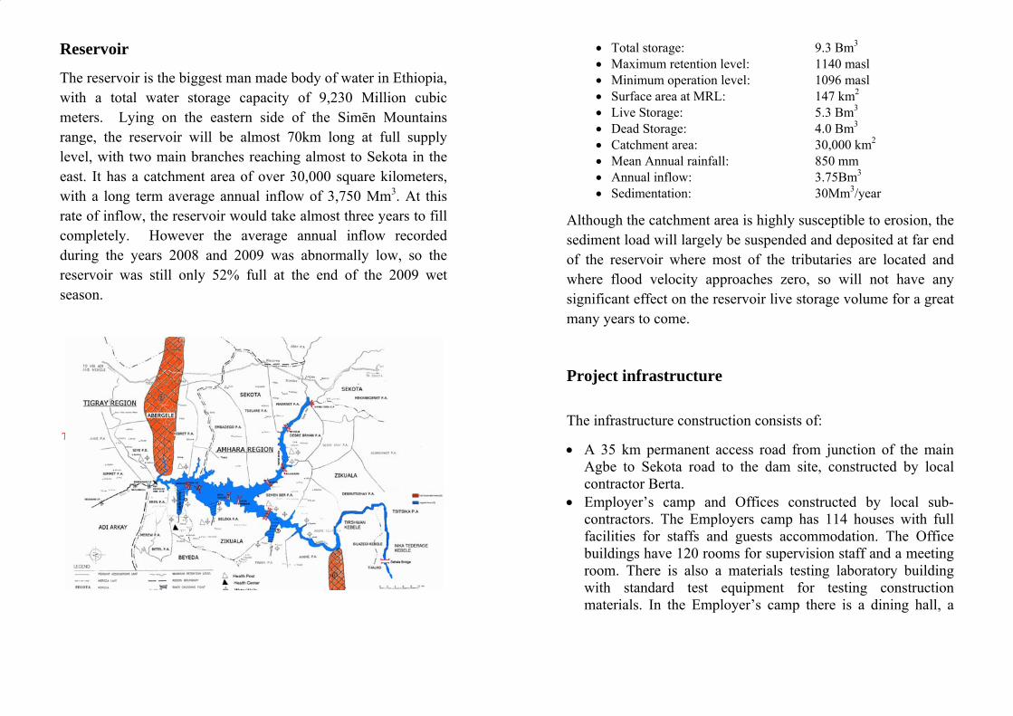
The reservoir is the biggest man made body of water in Ethiopia, with a total water storage capacity of 9,230 Million cubic meters. Lying on the eastern side of the Simēn Mountains range, the reservoir will be almost 70km long at full supply level, with two main branches reaching almost to Sekota in the east. It has a catchment area of over 30,000 square kilometers, with a long term average annual inflow of 3,750 Mm3. At this rate of inflow, the reservoir would take almost three years to fill completely. However the average annual inflow recorded during the years 2008 and 2009 was abnormally low, so the reservoir was still only 52% full at the end of the 2009 wet season.
Tekeze Arch Dam
• Total storage: 9.3 Bm3 • Maximum retention level: 1140 masl • Minimum operation level: 1096 masl • Surface area at MRL: 147 km2 • Live Storage: 5.3 Bm3 • Dead Storage: 4.0 Bm3 • Catchment area: 30,000 km2 • Mean Annual rainfall: 850 mm • Annual inflow: 3.75Bm3 • Sedimentation: 30Mm3/year
Although the catchment area is highly susceptible to erosion, the sediment load will largely be suspended and deposited at far end of the reservoir where most of the tributaries are located and where flood velocity approaches zero, so will not have any significant effect on the reservoir live storage volume for a great many years to come.
Project infrastructure
The infrastructure construction consists of:
• A 35 km permanent access road from junction of the main Agbe to Sekota road to the dam site, constructed by local contractor Berta.
• Employer’s camp and Offices constructed by local sub-contractors. The Employers camp has 114 houses with full facilities for staffs and guests accommodation. The Office buildings have 120 rooms for supervision staff and a meeting room. There is also a materials testing laboratory building with standard test equipment for testing construction materials. In the Employer’s camp there is a dining hall, a

cluswan
• WreEmovsu
• Comcobr
Tek
ub houswimmingnd squas
Water foservoir mployerverhead ubstationommuniedia, in
onnectioroadband
keze proje
se withg pool, sh court or dom
and pur’s camp
distribn. ications
ncludingons, wird intern
ect infrast
h TVs afootball
mestic cumped p and elbution
s are prog a mobreless tenet conn
tructure
and varl field, b
onsumpto a wectric pnetwor
ovided bile netwelephoneection.
rious rebasket b
ption iswater trower is rk fed
by ETCwork toe conne
creationball cou
s extracreatmenfed to t
d from
C througwer, VSections
nal faciurt tenn
cted front plant the camp
m the
gh a vaSAT teland a
lities, anis court
om thein the
p via anTekeze
ariety oflephonesatellite
a t
e e n e
f e e
Dam and appurtenance structures
The Arch Dam is a double curvature arch dam which is able to withstand the heavy pressure of the reservoir water. It is 188 meter high and 450 meters wide and was constructed from mass concrete. Currently it is tallest arch dam in Africa.
The Dam is located in a narrow gorge and its construction was not feasible by the conventional construction machinery, so three special cable way cranes, each with carrying capacity of 20 tones, span across the gorge to transport/placement of dam concrete and other construction machinery and equipment along with work personnel.
Arch Dam upstream view

Construction of the dam required 1,100million cubic meters of concrete, which accounted for 75% of the project cost and required 42 months of continuous concrete placement, 24 hours a day, 7 days a week.
Low Level Outlets (Spillway) structure and gates The Low Level Outlets were designed to discharge the Probable Maximum Flood (PMF) after routing through the reservoir but they will also be used to empty a part of the reservoir in case of emergency for dam safety and to enable exceptional maintenance. The arrangement selected was 4 mid-level outlets located in the central part of the dam, capable of releasing a total
Arch Dam downstream view
discharge of 4500 m3/s under the maximum water level (MWL). The water will discharge into the river bed far from the dam toe.
The Low Level Outlets consists of:
Four Radial gates were installed downstream of the dam and designed to open and close under full upstream water pressure and with clear outlet openings 5.6 m wide and 6.0 m high and a total weight of 114 tones. Each one is operated by two hydraulic cylinders, enclosed control modules and each module including a Hydraulic Power Units (HPU) and a local Electrical Control Cabinet.
Four low level outlets (LLO)

Four Fixed Wheel Gates were installed upstream of the dam to facilitate maintenance of the Radial Gates and have clear outlet opening 5.6 m wide and 8.0 m high and a total weight of 195 tones . They are operated by hydraulic cylinders with extension stems and module including an HPU and a local Electrical Control Cabinet.
Compensation Outlet valve
1.4 m diameter Howell-Bunger type valve was installed to release the compensation discharge water for the downstream side users during construction period and subsequently during maintenance of the units, and is designed to release regulated flows up to 45 m3/s. The installed valve disperses the water jet downstream of the dam, to avoid scoring of the dam toe.
Dam instrumentation
To assess the performance and continuing assurance of the safety of the dam and structural behavior during construction, first filling of the reservoir and during long-term service operation, dam instrumentation and monitoring equipment is basic. The Tekeze arch dam comprises pendulums, permanent long base multipoint borehole extensometers, jointmeters, electric piezometers - reservoir level, Long term thermometers, accelerographs, leakage measurement and monitoring data acquisition and storage
Dam Traction Lifts: Main access to the dam inspection galleries between levels 1140.0 masl and 985.0 masl is provided in two stages serviced by two traction lift. Emergency escape ladders with cross-over platforms also provided within the wells to cover complete descent of each lift travel.

Diversion tunnels and Bonneted gates Two diversion tunnels (No.1 & No.2) were designed to pass a 1 in 2 years flood (1026 m3/s) without overtopping the cofferdams. Larger floods that occurred during construction of the dam were allowed to flow over temporary spillways formed by leaving low blocks in the dam.
When the dam was sufficiently high to allow reservoir impounding to commence, tunnel No.1 was plugged with concrete and tunnel No. 2, was closed by means of two bonneted slide gates with clear opening of 2.6 m by 2.6 and operated by a hydraulic hoist. During the early stages of reservoir impounding, these gates allowed the release of compensation flows into the river, downstream of the dam, until the reservoir
level reached the low level outlets. They also provide a means of drawing down the reservoir level below the low level outlets, in an emergency situation.
The diversion works include:
• a 25 m high concrete, upstream cofferdam • a 8 m high earthfill, downstream cofferdam • two 7 m diameter, an average of 433m long horseshoe shape
diversion tunnels,
Waterways, Power Intake structure and Intake gate
Water to power the turbines enters the power waterways through the power intake structure and immediately passes into a 350 m long, concrete lined headrace tunnel, 7.25m in diameter. It then flows down a 120m deep vertical shaft before branching in the concrete lined manifold to the four steel lined penstock tunnels.
Bonnet gate HPU inside the Dam Gallery
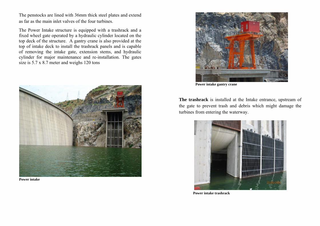
The penstocks are lined with 36mm thick steel plates and extend as far as the main inlet valves of the four turbines.
The Power Intake structure is equipped with a trashrack and a fixed wheel gate operated by a hydraulic cylinder located on the top deck of the structure. A gantry crane is also provided at the top of intake deck to install the trashrack panels and is capable of removing the intake gate, extension stems, and hydraulic cylinder for major maintenance and re-installation. The gates size is 5.7 x 8.7 meter and weighs 120 tons
Power intake
The trashrack is installed at the Intake entrance, upstream of the gate to prevent trash and debris which might damage the turbines from entering the waterway.
Power intake gantry crane
Power intake trashrack

Underground powerhouse and Electro-mechanical equipment
The Powerhouse was constructed underground, in a 68,000m3 cavern, 98m long, 38m high and 18m wide, excavated inside the massive limestone rock on the right bank of the river, by conventional drilling and blasting method.
Underground powerhouse: Excavation completed view
Four vertical Frances Reaction turbines, each having 75 MW capacities, were installed to convert the potential energy of the stored water in the reservoir into rotational mechanical energy. The runners are cast and welded stainless steel with a diameter of 2.75m with total weight of each is 13 tones.
Underground powerhouse: on service

Shaft and runner assembly
Shaft runner assembly installation
Eachto mfrequprogrcapab
Gover
h Govermaintainuency.rammabble of st
rnor contr
rnor insn the g
Eachble PIDtable, sa
rol system
stalled isgenerati
goverD (propoafe and e
m
B
s to coning unirnor iortional effective
Butterfly
Four(Butteat the each tuflow, tturbinepart ofand shnormalCondit
ntrol andit’s spes an
integrae contro
valve
Main rfly typ
spiral urbine toto shut-oe and stf the authutdownl andtions.
d adjust eed an
electrated de
ol of the
Inlet pe) are i
case io controoff flowtop the tomatic n sequed eme
the watnd the ronic, erivative turbine
Valvesnstalledinlet ofol waterw to the
unit asstart-upence inergency
ter flowsystemdigital,
e) type,es.
s d f r e s p n y
w m
, ,

Generator and associated equipment installed in the powerhouse
The four generators of Tekeze hydropower plant are totally enclosed, vertical salient-pole type, F class of insulation and an air cooled generator with guaranteed generator efficiency of 98.3% and rated out of 86.7/78 MVA/MW at rated generator voltage 13.8 kv, rated speed of 300 RPM, rated frequency 50 Hz, power factor cos ø 1. The generator includes:
The stator which consists of frame, core and winding and weights 106 ton, were transported to site in split of three sections, assembled and tested at site. The stator has a diameter of 7.5m and a height of 1.45m is fabricated from steel frame and the core with inner diameter of 5.6m and height of 1.35m.
Rotospiderotor stackweigh
SCADremothe instalcontrsubstpowe
or whicher is the
parts ked at sihts 185
DA sysote con
units lled irol builtation erhouse
h is F-clheavieswere ste and ttons.
stem forntrol of
wasin theding of
andoffices.
lass insust equipseparatelthe diam
r f s e f d .
ulation cpment inly trans
meter is
consistsnstalled sported of 5.6 m
of 20 pat Teketo site
m and 1
poles, rimeze projee, stack.73 m h
ms, andect. Theked andhigh and
d e d d

Each unit has its own Local and Remote Control and Protection systems.
All auxiliary systems installed in the powerhouse were supplied in duplex, one in duty and the other standby for the balance of plant equipments including cooling water system, drainage and dewatering system, compressed air system, fire alarm and protection system, ventilation and air conditioning system (HVAC), sanitary system, service water system, emergency diesel generator, monitoring equipments etc for reliable, safe and stable operation of turbine-generator equipments and the power plant.
In the Powerhouse, two overhead bridge cranes were provided, with total lifting capacity of 220 tons, and were used initially for intensive plant installation work and subsequently for maintenance duties. Each crane spans 18 meters. The two cranes are designed to work together when lifting very heavy loads, such as the generator rotors.
Powerhouse bridge crane
The Outlet structure comprises 4 tailrace tunnels to discharge water back to the river from the turbines, after generation. The Draft tube stoplogs and hoist are used to close each draft tube individually, to isolate a turbine from the tailrace water whenever it is necessary to perform an internal inspection and maintenance. The stoplogs are handled by an electrically driven gantry hoist running on rails above the gate slots.

Outlet structure
The four 90MVA Transformers each 90 tones were manufactured in China and transported to site with specially imported transport trucks so that the existing road bridges would not be damaged.
The locate
Transfoed at the
ormer pe outlet
platformstructur
m housere, abov
es the fove the ta
our transailrace tu
sformerunnels
rs and iss

Substations and Transmission Line
A new 230kV Substation and Control Building were constructed at Tekeze and at the existing substation at Mekele an extension 230 kv Substation were constructed to accommodate the new transmission line. The 105 km long, double circuit 230kV Transmission Line was constructed to transmit the generated power from Tekeze substation to Mekele substation and then to the National Grid. The Transmission Line includes a grounding line with OPGW fiber optic cables to enable communications with all of EEPCO’s other hydropower stations and with the Load Dispatch Center in Addis Ababa.
Both the Substations and the Transmission Line were constructed at an early stage in the project schedule to provide back-feed power from the National Grid from Mekele substation for the Main Civil and Electromechanical Contractors, to reduce costs and cut the amount of fuel used by the temporary diesel generators originally installed to supply construction power.
Tekeze Substation
Environmental impacts and mitigation measures
Tekeze hydroelectric power project has both positive and negative impacts but, on balance, the positive impacts significantly outweigh the negative ones. There was no displacement or resettlement of the local population around the reservoir. The construction and operation of the project led to a variety of changes in the local and wider environment. Many of the effects are beneficial, particularly the impact at both regional and national levels of increasing the availability of electrical energy, and the potential to develop the local economy through improved infrastructure and employment opportunities. Major impacts of the project are summarized as follows.
Positive Impacts
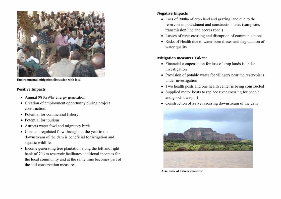
• Annual 981GWhr energy generation. • Creation of employment opportunity during project
construction. • Potential for commercial fishery • Potential for tourism • Attracts water fowl and migratory birds • Constant regulated flow throughout the year to the
downstream of the dam is beneficial for irrigation and aquatic wildlife.
• Income generating tree plantation along the left and right bank of 70 km reservoir facilitates additional incomes for the local community and at the same time becomes part of the soil conservation measures.
Environmental mitigation discussion with local
Negative Impacts • Loss of 900ha of crop land and grazing land due to the
reservoir impoundment and construction sites (camp site, transmission line and access road )
• Losses of river crossing and disruption of communications • Risks of Health due to water born dieses and degradation of
water quality
Mitigation measures Taken: • Financial compensation for loss of crop lands is under
investigation • Provision of potable water for villagers near the reservoir is
under investigation • Two health posts and one health center is being constructed • Supplied motor boats to replace river crossing for people
and goods transport • Construction of a river crossing downstream of the dam
Arial view of Tekeze reservoir

American tourists crossing man made Tekeze Lake (August 2007)
Site Visit
As the great chairman Mao Zedong said, “The genuine knowledge originates in direct experience.” Tekeze hydropower project successfully accomplished the saying during the construction period, by delivering the required practical education to university students, researchers, and every individual participated on the project and every visitors. The total number of people visited this project exceeds 50,000 to date.
During the construction period of the project various visitors have made a trip to the project which includes.
• Higher Government officials: the President, the prime Minister and other State Ministers
• Regional Governors • Universities, Colleges and High Schools • Researchers from local and foreign universities • Defense military from different region of the country • Youth and women associations • Investors from local and abroad • NGO’s
Social Activities
The project also played a great role creating awareness on HIV/AIDS preventing and control preparing World Aids Day ceremonies, organizing sport games, participating in tree plantation etc.