Embed Size (px)
Citation preview
National Aeronautics and Space Administration
Overview of NASA ISRU Technology Development
Diane Linne1, Jerry Sanders2, Molly Anderson2, Koorosh Araghi2, Stan Starr3, Nantel Suzuki4, Terry
O’Malley1, David Eisenman5
Presented at the AIAA SciTech ForumJanuary 9, 2017
1NASA Glenn Research Center2NASA Johnson Space Center3NASA Kennedy Space Center4NASA Headquarters5Jet Propulsion Lab
https://ntrs.nasa.gov/search.jsp?R=20170004388 2019-04-10T13:20:57+00:00Z
Introduction
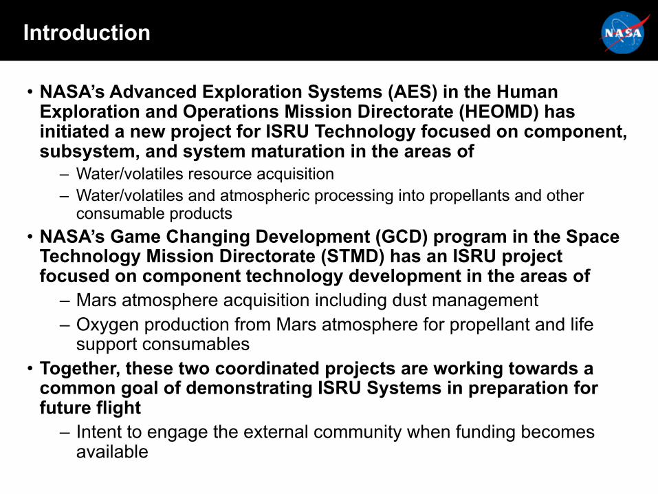
• NASA’s Advanced Exploration Systems (AES) in the Human Exploration and Operations Mission Directorate (HEOMD) has initiated a new project for ISRU Technology focused on component, subsystem, and system maturation in the areas of
– Water/volatiles resource acquisition– Water/volatiles and atmospheric processing into propellants and other
consumable products• NASA’s Game Changing Development (GCD) program in the Space
Technology Mission Directorate (STMD) has an ISRU project focused on component technology development in the areas of
– Mars atmosphere acquisition including dust management– Oxygen production from Mars atmosphere for propellant and life
support consumables• Together, these two coordinated projects are working towards a
common goal of demonstrating ISRU Systems in preparation for future flight
– Intent to engage the external community when funding becomes available
What is In Situ Resource Utilization (ISRU)?
3
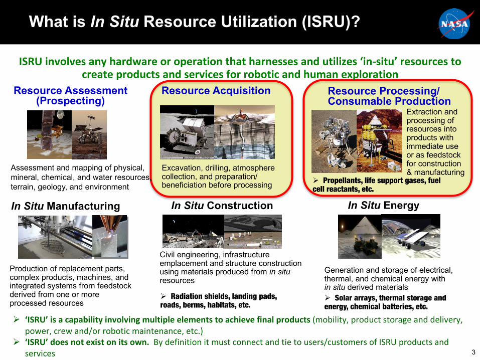
Ø ‘ISRU’isacapabilityinvolvingmultipleelementstoachievefinalproducts(mobility,productstorageanddelivery,power,crewand/orroboticmaintenance,etc.)
Ø ‘ISRU’doesnotexistonitsown.Bydefinitionitmustconnectandtietousers/customersofISRUproductsandservices
ISRUinvolvesanyhardwareoroperationthatharnessesandutilizes‘in-situ’resourcestocreateproductsandservicesforroboticandhumanexploration
Resource Assessment (Prospecting)
In Situ Manufacturing
Assessment and mapping of physical, mineral, chemical, and water resources, terrain, geology, and environment
Production of replacement parts, complex products, machines, and integrated systems from feedstock derived from one or more processed resources
Resource Acquisition
In Situ Construction
Civil engineering, infrastructure emplacement and structure construction using materials produced from in situ resources
Excavation, drilling, atmosphere collection, and preparation/ beneficiation before processing
Resource Processing/ Consumable Production
In Situ Energy
Extraction and processing of resources into products with immediate use or as feedstock for construction & manufacturing
Generation and storage of electrical, thermal, and chemical energy with in situ derived materialsØ Solar arrays, thermal storage and energy, chemical batteries, etc.
Ø Radiation shields, landing pads, roads, berms, habitats, etc.
Ø Propellants, life support gases, fuel cell reactants, etc.
Decisions To Be Made Can Have Long Term Implications
4
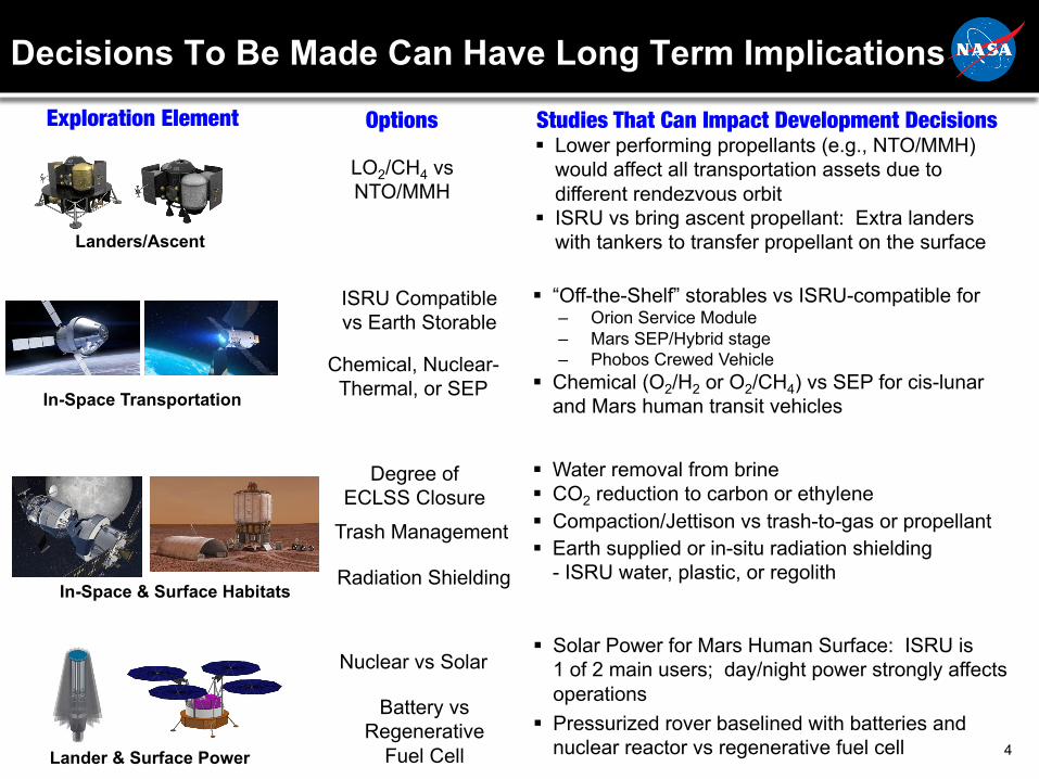
Exploration Element
Lander & Surface Power
In-Space & Surface Habitats
In-Space Transportation
Landers/Ascent
LO2/CH4 vs NTO/MMH
§ Lower performing propellants (e.g., NTO/MMH)would affect all transportation assets due to different rendezvous orbit
§ ISRU vs bring ascent propellant: Extra landers with tankers to transfer propellant on the surface
Studies That Can Impact Development Decisions
ISRU Compatible vs Earth Storable
§ “Off-the-Shelf” storables vs ISRU-compatible for ‒ Orion Service Module‒ Mars SEP/Hybrid stage‒ Phobos Crewed Vehicle
§ Chemical (O2/H2 or O2/CH4) vs SEP for cis-lunar and Mars human transit vehicles
Chemical, Nuclear-Thermal, or SEP
Degree of ECLSS Closure
Trash Management
Radiation Shielding
§ Water removal from brine§ CO2 reduction to carbon or ethylene§ Compaction/Jettison vs trash-to-gas or propellant§ Earth supplied or in-situ radiation shielding
- ISRU water, plastic, or regolith
Nuclear vs Solar
Battery vs Regenerative
Fuel Cell
§ Solar Power for Mars Human Surface: ISRU is 1 of 2 main users; day/night power strongly affects operations
§ Pressurized rover baselined with batteries and nuclear reactor vs regenerative fuel cell
Options
ISRU Technology Development Needed Now
• ISRU is a disruptive capability– Enables more affordable exploration than today’s paradigm – Requires integrated system design approach– Allows more sustainable architectures to be developed
§ Understand the ripple effect in the other Exploration Elements- MAV, EDL, Habitats, Life Support, Power
• Every Exploration Element except ISRU has some flight heritage (power, propulsion, habitats, landers, life support, etc.)– ISRU will require a flight demonstration mission on Mars before it will be included
in the critical path• Mission needs to be concluded at least 10 years before first human landed mission to ensure lessons
learned can be incorporated into final design
– ISRU Formulation team has generated a (still incomplete) list of over 75 technical questions on more than 40 components and subsystems that need to be answered before the ‘right’ ISRU system will be ready for flight
5

ISRU State-of-the-Art: Resource Acquisition, Processing, Consumables Production
6
§ Significant work has been performed to demonstrate feasibility of ISRU concepts and develop components and technologies (TRL 1-3)
§ Moon/Mars‒ Mars atmosphere collection, separation, and processing into O2 or O2/CH4‒ Lunar regolith excavation, beneficiation, and processing to extract O2‒ Civil engineering/soil stabilization
§ Asteroid‒ Acquisition concept work is just starting through STMD-ESI, BAAs, and SBIR/STTRs
§ Some development & testing has been performed at the system level (TRL 4-6)§ Moon (Lab, Analog sites)
‒ RESOLVE, PILOT, ROxygen§ Mars (Lab, Environment)
‒ Portable Mars Production Plant (early ‘90s), Mars Sabatier/Water Electrolysis System (Mars env. chamber ‘00), MIP (flight experiment for cancelled Mars ’01)
‒ MOXIE scheduled to fly on Mars 2020 mission
§ However, significant work is needed to mature these technologies§ Development & testing much closer to full-scale for human mission needs§ Much longer operational durations§ Much more testing to validate performance under relevant environmental conditions§ Integrate many components and subsystems into system prototypes§ Realize synergy between ISRU and other system technologies, such as life support/fuel
cell, power, surface mobility
ISRU Critical Challenges That Need to Be Addressed
• What is the ‘right’ set of components and subsystems to enable production of mission consumables from either regolith or atmospheric resources at a variety of destinations?
• What is the performance and life that can be expected from the ISRU system in the actual environment?
• How does the ISRU system integrate and interact with other systems (e.g., power, lander, life support, etc.)?– ConOps– Power sharing– Total surface thermal management– Maintenance and refurbishment
7
Overall Goal: System-level TRL 6 to support future Pathfinder missions
ISRU Technology Project
• Scope: Develop the component, subsystem, and system technology to enable production of mission consumables from either regolith or atmospheric resources at a variety of destinations
• Objective: Advance ISRU System-level technology readiness to prepare for flight demonstrations– Initial focus
• Critical technology gap closure• Component development in relevant environment (TRL 5)
– Interim Goals• ISRU subsystems tests in relevant environment (Subsystem TRL 6)
– End-Goals• End-to-end ISRU system tests in relevant environment (System TRL 6)• Integrated ISRU-Exploration elements demonstration in relevant environment
8
Provide Exploration Architecture Teams with validated, high-fidelity answers for mass, power, and volume of ISRU Systems
Example of ISRU Components and Subsystem Definition
9
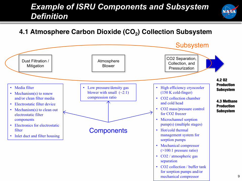
CO2 Separation, Collection, and Pressurization
Atmosphere Blower
Dust Filtration / Mitigation
• Media filter• Mechanism(s) to renew
and/or clean filter media• Electrostatic filter device• Mechanism(s) to clean out
electrostatic filter components
• Electronics for electrostatic filter
• Inlet duct and filter housing
• Low pressure/density gas blower with small (~2:1) compression ratio
• High efficiency cryocooler(150 K cold-finger)
• CO2 collection chamber and cold head
• CO2 mass/pressure control for CO2 freezer
• Microchannel sorption pump(s) (multiple stages)
• Hot/cold thermal management system for sorption pumps
• Mechanical compressor (>100:1 pressure ratio)
• CO2 / atmospheric gas separation
• CO2 collection / buffer tank for sorption pumps and/or mechanical compressor
4.2 O2 Production Subsystem
4.3 Methane Production Subsystem
4.1 Atmosphere Carbon Dioxide (CO2) Collection Subsystem
Components
Subsystem
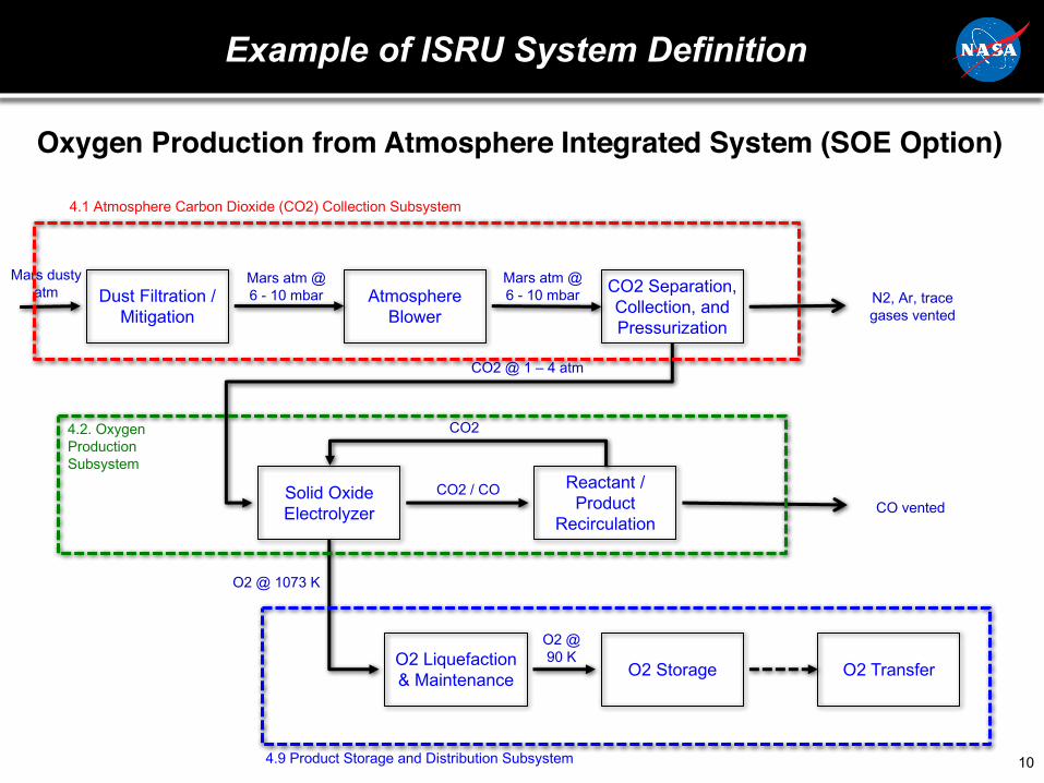
Example of ISRU System Definition
10
CO2 Separation, Collection, and Pressurization
Atmosphere Blower
Dust Filtration / Mitigation
Reactant / Product
Recirculation
Solid Oxide Electrolyzer
O2 Liquefaction & Maintenance O2 Storage O2 Transfer
N2, Ar, trace gases vented
CO vented
Mars dusty atm
Mars atm @ 6 - 10 mbar
Mars atm @ 6 - 10 mbar
CO2 @ 1 – 4 atm
CO2 / CO
CO2
O2 @ 1073 K
O2 @ 90 K
4.1 Atmosphere Carbon Dioxide (CO2) Collection Subsystem
4.2. Oxygen Production Subsystem
4.9 Product Storage and Distribution Subsystem
Oxygen Production from Atmosphere Integrated System (SOE Option)

ISRU Fuel and Oxygen Production End-to-End Integrated System
11
CO2 Separation, Collection, and Pressurization
Atmosphere Blower
Dust Filtration / Mitigation
O2 Liquefaction & MaintenanceO2 StorageO2 Transfer
N2, Ar, trace gases vented
Mars dusty atm
Mars atm @ 6 - 10 mbar
Mars atm @ 6 - 10 mbar
CO2 @ 1 – 4 atm
O2 @ ~90 K
Water Electrolysis
O2 Dryer
4.1 Atmosphere Carbon Dioxide (CO2) Collection Subsystem
4.3 Methane Fuel Production Subsystem
4.9 Product Storage and Distribution Subsystem
Sabatier ReactorH2O / gas separator
(condenser)
H2 / CH4 separator
H2 Dryer
H2O Collection, Clean-up, and
StorageSoil DryerSoil Hoppers /
TransferSoil Excavation
for Water
CH4 DryerH2O, H2,
CH4
H2, CH4 CH4
H2
Wet / hydratedsoil
Dried soil
Contaminated
H2OH2O
CH4 Liquefaction & MaintenanceCH4 StorageCH4 Transfer
CH4 @ ~110 K
H2H2O
4.7 & 4.8 Excavation and Soil Processing Subsystems
4.4 Water Electrolysis Subsystem

ISRU Technology Project Schedule (Notional)
12
Components
Subsystems
Systems
LEGEND
Soil water-based ISRU (top track) likely to require more time to develop to TRL 5/6 than Mars atmosphere-based ISRU (bottom track)
e.g., Sabatier, RWGS, SOE stacks, species separators
e.g., mobility platform, modular power
e.g., SOE stacks, H2O electrolyzers, CO2acquisition
e.g., power, thermal rejection, autonomy, interfaces to life support, MAV
O2/CH4 liquefaction & storage
e.g., mobility platform interfaces
e.g., soil transfer, ice drill, water clean-up
FY18 FY19 FY20 FY21 FY22 FY23 FY24 FY25 FY26 FY27 FY28FY17
SBIR infusion AES, STMD Project
ISRU Technology Development
Phase C/DPhase A Phase B
SRR PDR CDR Launch
E2E ISRU System Test: Regolith/Water - Based
ISRU-SurfaceSystemsIntegrated
Demonstration(s)
E2E ISRU System Test: Atmosphere-Based
Excav. and Soil Process. SubsystemsTest
Notional ISRU Demonstration Mission(s)
Atm. Collection and Processing SubsystemsTest
Excavation and Soil Processing Component Maturation
Atmosphere Collection and Processing Component Maturation
Moon / Mars / Asteroid
Regolith/Water-based ISRU
Mars Atmosphere -based ISRU
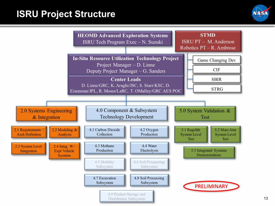
ISRU Project Structure
13
In-Situ Resource Utilization Technology ProjectProject Manager – D. Linne
Deputy Project Manager – G. Sanders
2.0 Systems Engineering & Integration
4.0 Component & Subsystem Technology Development
5.0 System Validation & Test
4.1 Carbon Dioxide Collection
4.2 Oxygen Production
4.3 Methane Production
4.4 Water Electrolysis
5.1 Regolith System Level
Test
5.2 Mars AtmSystem Level
Test
2.1 Requirements / Arch Definition
2.2 Modeling & Analysis
2.3 System Level Integration
2.4 Integ. W / Expl Vehicle
Systems
STMDISRU PT – M. Anderson
Robotics PT – R. Ambrose
HEOMD Advanced Exploration SystemsISRU Tech Program Exec – N. Suzuki
Game Changing Dev
CIF
SBIR
STRG
PRELIMINARY
5.3 Integrated Systems Demonstrations
Center LeadsD. Linne/GRC, K. Araghi/JSC, S. Starr/KSC, D.
Eisenman/JPL, R. Moses/LaRC, T. OMalley/GRC AES POC
4.5 Mobility Subsystem
4.6 Soil Prospecting Subsystem
4.7 Excavation Subsystem
4.8 Soil Processing Subsystem
4.9 Product Storage and Distribution Subsystem

FY17 Overview
14

2.0 Systems Engineering and Integration
• Exploration Mission Architecture teams– Provide ISRU systems mass, power, volume, and concept of operations input to
mission architecture teams– Work with other projects to identify common technology needs (e.g., water
electrolysis) and dependent technology needs (e.g., mobility platform)• System Modeling
– Develop system model framework to link physics-based component models into integrated system model
– Perform trade study on effects of mass, power, volume of Mars oxygen/fuel production system as a function of water resource type (hydrated minerals, icy soils, deep ice)
• System Level Integration - Thermal Management– Evaluate system-level thermal integration challenges and identify and analyze
potential solutions• Hot and cold components within the system• Synergistic use of waste heat from external to ISRU system
• Autonomy and Control– Evaluate challenges and potential solutions for long-duration untended operation,
with focus on autonomous navigation and operation of excavation and delivery subsystem
15

4.1.1 Dust Filtration and Mitigation
• Scroll Media Filters– Create physics-based model and validate
• Existing data from testing in Mars flow loop• Possible test data from MOXIE (Mars Oxygen
In-Situ Resource Utilization Experiment)– Design full-scale media filter component for
fabrication and testing in FY18• Electrostatic Precipitators
– Develop and test electrostatic precipitator to remove dust from Mars atmosphere at the intake to the ISRU plant
– Create physics-based model and validate with test data
– Use model to optimize geometry • Cyclone Separators
– Evaluate past lunar ISRU work and on-going SBIR for applicability to Mars atmosphere dust filtration
16
Scroll filter designed for Space Station
Electrostatic Precipitator Design
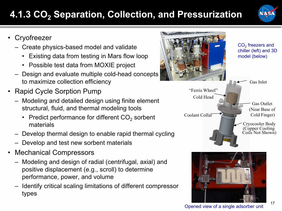
4.1.3 CO2 Separation, Collection, and Pressurization
• Cryofreezer– Create physics-based model and validate
• Existing data from testing in Mars flow loop• Possible test data from MOXIE project
– Design and evaluate multiple cold-head conceptsto maximize collection efficiency
• Rapid Cycle Sorption Pump– Modeling and detailed design using finite element
structural, fluid, and thermal modeling tools• Predict performance for different CO2 sorbent
materials– Develop thermal design to enable rapid thermal cycling– Develop and test new sorbent materials
• Mechanical Compressors– Modeling and design of radial (centrifugal, axial) and
positive displacement (e.g., scroll) to determine performance, power, and volume
– Identify critical scaling limitations of different compressor types
17
Gas Inlet
Gas Outlet (Near Base of Cold Finger)
Cryocooler Body(Copper Cooling Coils Not Shown)
Coolant Collar
“Ferris Wheel”Cold Head
CO2 freezers and chiller (left) and 3D model (below)
Opened view of a single adsorber unit
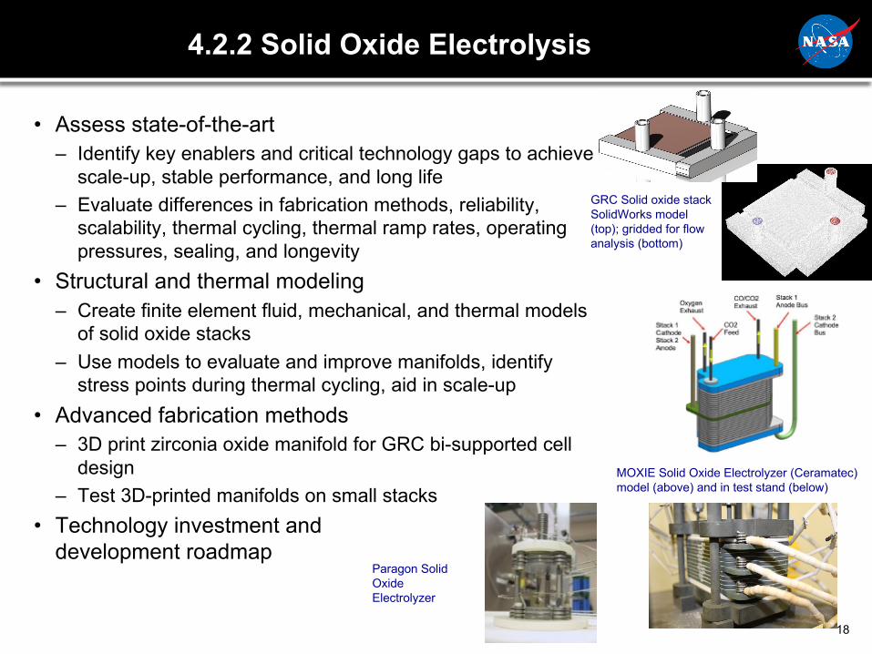
4.2.2 Solid Oxide Electrolysis
• Assess state-of-the-art– Identify key enablers and critical technology gaps to achieve
scale-up, stable performance, and long life– Evaluate differences in fabrication methods, reliability,
scalability, thermal cycling, thermal ramp rates, operating pressures, sealing, and longevity
• Structural and thermal modeling– Create finite element fluid, mechanical, and thermal models
of solid oxide stacks– Use models to evaluate and improve manifolds, identify
stress points during thermal cycling, aid in scale-up• Advanced fabrication methods
– 3D print zirconia oxide manifold for GRC bi-supported cell design
– Test 3D-printed manifolds on small stacks• Technology investment and
development roadmap
18
GRC Solid oxide stack SolidWorks model (top); gridded for flow analysis (bottom)
MOXIE Solid Oxide Electrolyzer (Ceramatec) model (above) and in test stand (below)
Paragon Solid Oxide Electrolyzer
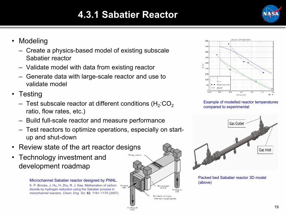
4.3.1 Sabatier Reactor
• Modeling– Create a physics-based model of existing subscale
Sabatier reactor– Validate model with data from existing reactor– Generate data with large-scale reactor and use to
validate model• Testing
– Test subscale reactor at different conditions (H2:CO2ratio, flow rates, etc.)
– Build full-scale reactor and measure performance– Test reactors to optimize operations, especially on start-
up and shut-down• Review state of the art reactor designs • Technology investment and
development roadmap
19
Example of modelled reactor temperatures compared to experimental
Packed bed Sabatier reactor 3D model (above)Microchannel Sabatier reactor designed by PNNL.
K. P. Brooks, J. Hu, H. Zhu, R. J. Kee, Methanation of carbon dioxide by hydrogen reduction using the Sabatier process in microchannel reactors. Chem. Eng. Sci. 62, 1161–1170 (2007).
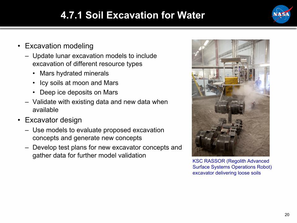
4.7.1 Soil Excavation for Water
• Excavation modeling– Update lunar excavation models to include
excavation of different resource types• Mars hydrated minerals• Icy soils at moon and Mars• Deep ice deposits on Mars
– Validate with existing data and new data when available
• Excavator design– Use models to evaluate proposed excavation
concepts and generate new concepts– Develop test plans for new excavator concepts and
gather data for further model validation
20
KSC RASSOR (Regolith Advanced Surface Systems Operations Robot) excavator delivering loose soils

4.8.2 Soil Dryers
• Closed processors– Closed or partially closed reactor– Receives delivered regolith, extracts and separates water,
deposits spent regolith for disposal• Open processors
– Process and extract the water at the site– Includes in-situ extraction of deep ice deposits in liquid or
gas phase– Complete testing of GRC in-situ processor concept
• Soil processing designs– Create models to evaluate proposed concepts and generate
new concepts– Develop designs for one batch and one in-situ concept– Develop test plans for soil processing concepts
21
Concept for open water extractionsoil processor
Screw Conveyor Drive soil processor concept
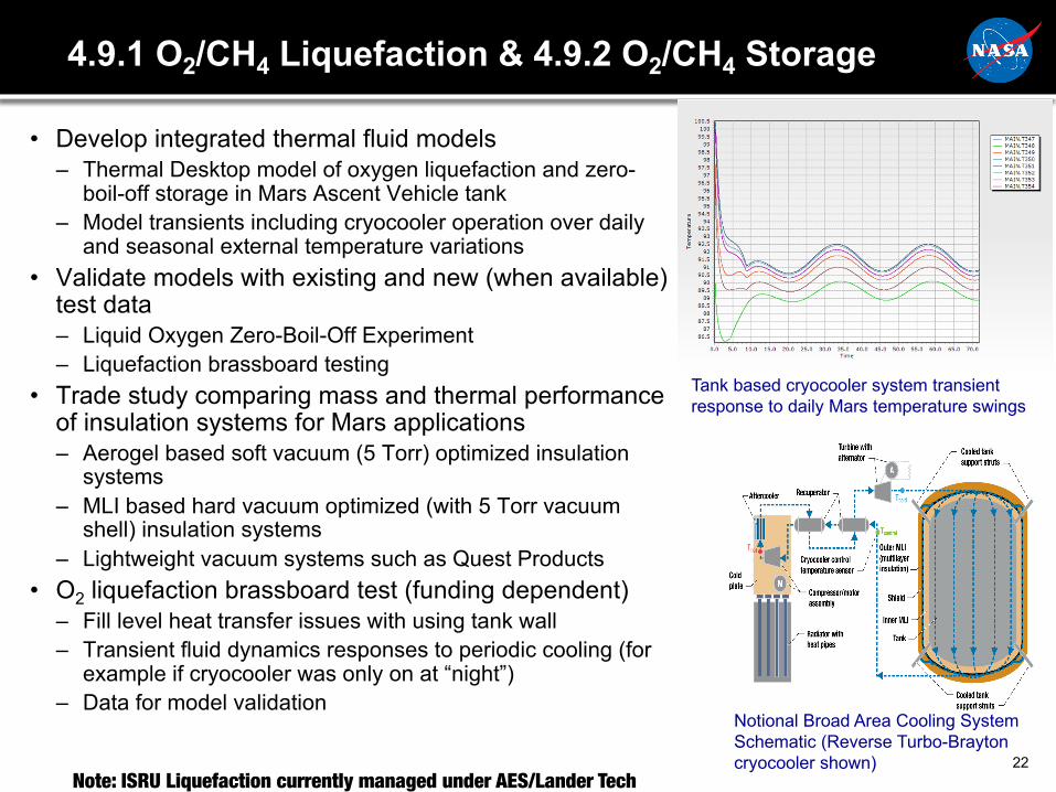
4.9.1 O2/CH4 Liquefaction & 4.9.2 O2/CH4 Storage
• Develop integrated thermal fluid models– Thermal Desktop model of oxygen liquefaction and zero-
boil-off storage in Mars Ascent Vehicle tank – Model transients including cryocooler operation over daily
and seasonal external temperature variations• Validate models with existing and new (when available)
test data– Liquid Oxygen Zero-Boil-Off Experiment– Liquefaction brassboard testing
• Trade study comparing mass and thermal performance of insulation systems for Mars applications– Aerogel based soft vacuum (5 Torr) optimized insulation
systems– MLI based hard vacuum optimized (with 5 Torr vacuum
shell) insulation systems– Lightweight vacuum systems such as Quest Products
• O2 liquefaction brassboard test (funding dependent)– Fill level heat transfer issues with using tank wall– Transient fluid dynamics responses to periodic cooling (for
example if cryocooler was only on at “night”)– Data for model validation
22
Notional Broad Area Cooling System Schematic (Reverse Turbo-Brayton cryocooler shown)
Tank based cryocooler system transient response to daily Mars temperature swings
Note: ISRU Liquefaction currently managed under AES/Lander Tech
Summary
• NASA ISRU Technology projects in HEOMD and STMD are developing ISRU technology for the Moon, asteroids, and Mars– Focus on acquisition and consumables production and storage– Component -> subsystem -> system progression
• Emphasis on testing in relevant environment early and often• Raise System-level TRL in preparation for potential
demonstration missions• Provide Exploration Architecture Teams with validated, high-
fidelity answers for mass, power, volume, and concept of operations
23