Embed Size (px)
Citation preview
Glenn Research Centerat Lewis Field
Overview of Multi-kilowatt Free-Piston Stirling Power Conversion Research at GRC
Steven M. Geng1, Lee S. Mason1, Rodger W. Dyson1, and L. Barry Penswick2
1Thermal Energy Conversion Branch, NASA Glenn Research Center 21000 Brookpark Rd., Cleveland, OH 44135, USA
2SEST Inc., 18000 Jefferson Park, Middleburg Hts, OH 44130, USA 1(216) 433-6145, [email protected]
Abstract. As a step towards development of Stirling power conversion for potential use inFission Surface Power (FSP) systems, a pair of commercially available 1 kW class free-pistonStirling convertors and a pair of commercially available pressure wave generators (which will beplumbed together to create a high power Stirling linear alternator test rig) have been procured forin-house testing at Glenn Research Center. Delivery of both the Stirling convertors and thelinear alternator test rig is expected by October, 2007. The 1 kW class free-piston Stirlingconvertors will be tested at GRC to map and verify performance. The convertors will later bemodified to operate with a NaK liquid metal pumped loop for thermal energy input. The highpower linear alternator test rig will be used to map and verify high power Stirling linearalternator performance and to develop power management and distribution (PMAD) methods andtechniques. This paper provides an overview of the multi-kilowatt free-piston Stirling powerconversion work being performed at GRC.
https://ntrs.nasa.gov/search.jsp?R=20080033114 2020-04-30T05:10:46+00:00Z
Glenn Research Centerat Lewis Field
Overview of Multi-Kilowatt Free-Piston Stirling Power Conversion at GRC
Presented to:The Space Technology and Applications International Forum
(STAIF-2008)Albuquerque, New Mexico
February 10 – 14, 2008
By:Steven M. Geng, Lee S. Mason, and Rodger W. Dyson
NASA Glenn Research Centerand
L. Barry PenswickSEST, Inc.
Glenn Research Centerat Lewis Field
Agenda
• Introduction
• Multi-kW Stirling Technology Development
• 1 kWe Stirling Convertors
– Performance Map Test
– NaK Heat Exchanger
• High Power Linear Alternator Test Rig
• Convertor Scale-up
• System Technology Demo Unit (TDU)
• Concluding Remarks
• Acknowledgements
Glenn Research Centerat Lewis Field
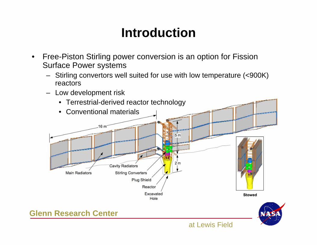
Introduction
• Free-Piston Stirling power conversion is an option for Fission Surface Power systems– Stirling convertors well suited for use with low temperature (<900K)
reactors– Low development risk
• Terrestrial-derived reactor technology• Conventional materials
Glenn Research Centerat Lewis Field
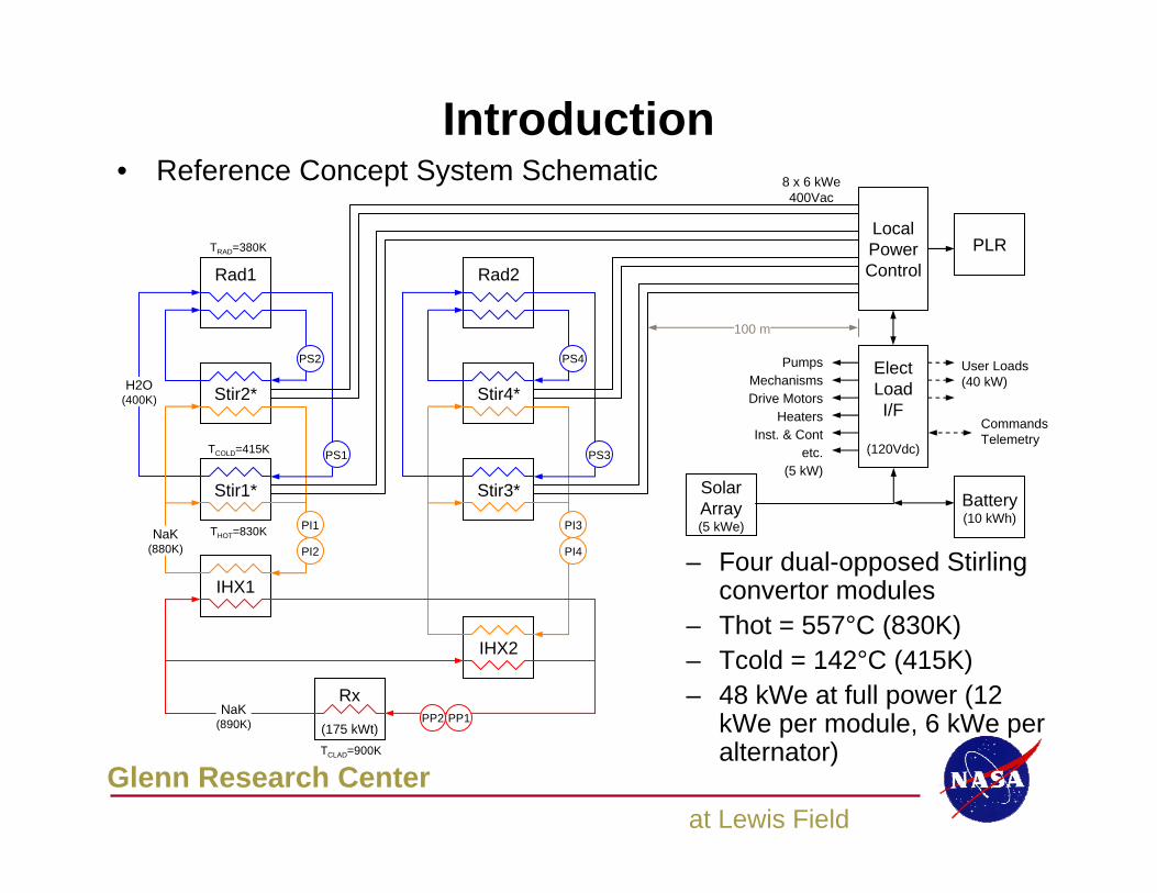
Introduction
– Four dual-opposed Stirling convertor modules
– Thot = 557°C (830K)– Tcold = 142°C (415K)– 48 kWe at full power (12
kWe per module, 6 kWe per alternator)
• Reference Concept System Schematic
Stir1*
Stir2*
Rad1
Stir3*
Stir4*
PI4
Rad2
PI3
PS3
PS4PS2
PS1
PI2
PI1
LocalPowerControl
PLR
ElectLoadI/F
(120Vdc)
SolarArray(5 kWe)
Battery(10 kWh)
IHX2
IHX1
Rx
(175 kWt)PP2 PP1
NaK(890K)
NaK(880K)
H2O(400K)
100 m
PumpsMechanismsDrive Motors
HeatersInst. & Cont
etc.(5 kW)
User Loads(40 kW)
CommandsTelemetry
8 x 6 kWe400Vac
THOT=830K
TCOLD=415K
TRAD=380K
TCLAD=900K
Glenn Research Centerat Lewis Field
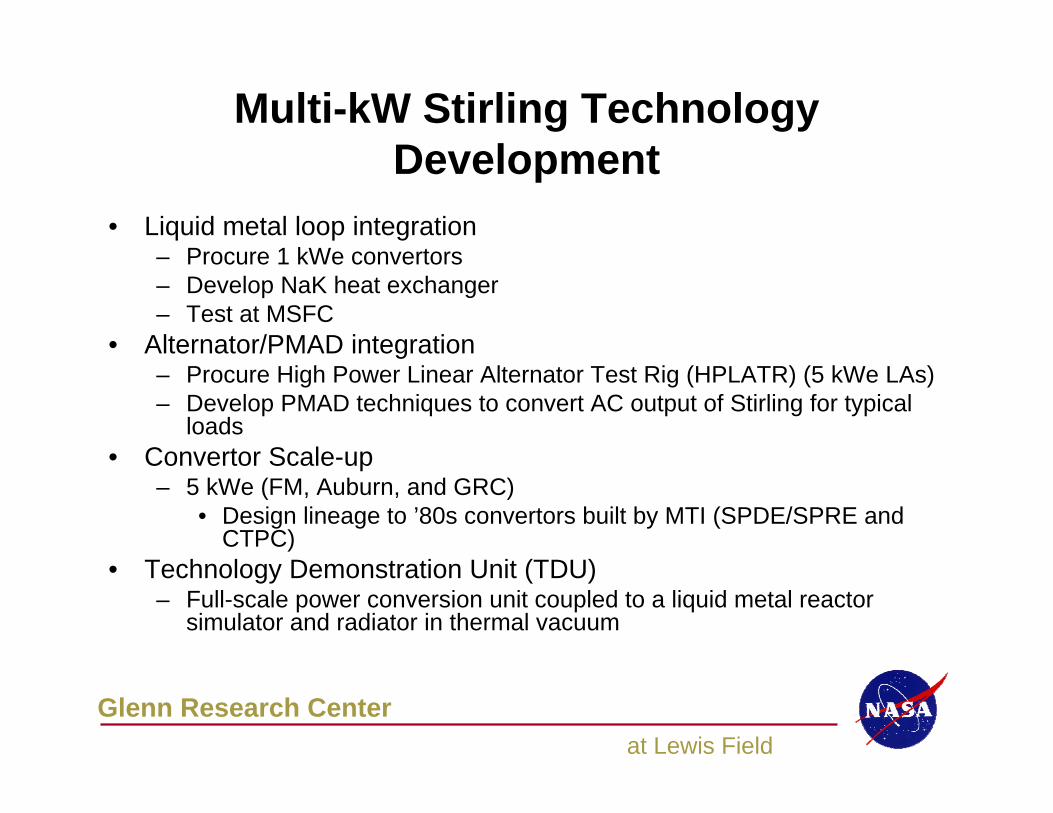
Multi-kW Stirling Technology Development
• Liquid metal loop integration– Procure 1 kWe convertors– Develop NaK heat exchanger– Test at MSFC
• Alternator/PMAD integration– Procure High Power Linear Alternator Test Rig (HPLATR) (5 kWe LAs)– Develop PMAD techniques to convert AC output of Stirling for typical
loads• Convertor Scale-up
– 5 kWe (FM, Auburn, and GRC)• Design lineage to ’80s convertors built by MTI (SPDE/SPRE and
CTPC)• Technology Demonstration Unit (TDU)
– Full-scale power conversion unit coupled to a liquid metal reactor simulator and radiator in thermal vacuum
Glenn Research Centerat Lewis Field
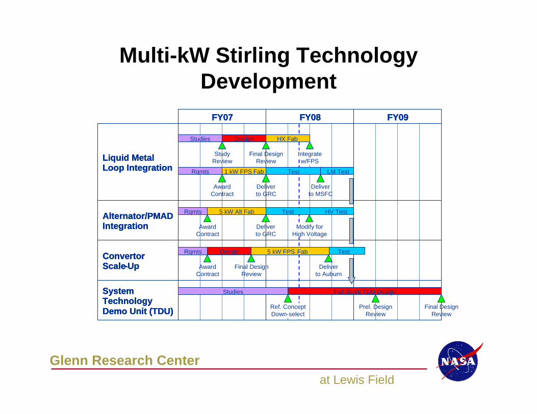
Multi-kW Stirling Technology Development
FY07 FY08 FY09
Liquid MetalLoop Integration
Alternator/PMADIntegration
ConvertorScale-Up
SystemTechnologyDemo Unit (TDU)
FY07 FY08 FY09FY07 FY08 FY09
Liquid MetalLoop Integration
Alternator/PMADIntegration
ConvertorScale-Up
SystemTechnologyDemo Unit (TDU)
Liquid MetalLoop Integration
Alternator/PMADIntegration
ConvertorScale-Up
SystemTechnologyDemo Unit (TDU) Final Design
ReviewRef. ConceptDown-select
Final DesignReview
Deliverto Auburn
Deliverto GRC
Deliverto MSFC
Deliverto GRC
Modify forHigh Voltage
AwardContract
AwardContract
Integratew/FPS
Final DesignReview
StudyReview
Design Test5 kW FPS Fab
Studies Full-Scale TDU Design
5 kW Alt Fab Test
Design
1 kW FPS Fab LM TestTest
HV Test
Studies HX Fab
Prel. DesignReview
AwardContract
Rqmts
Rqmts
Rqmts
Glenn Research Centerat Lewis Field
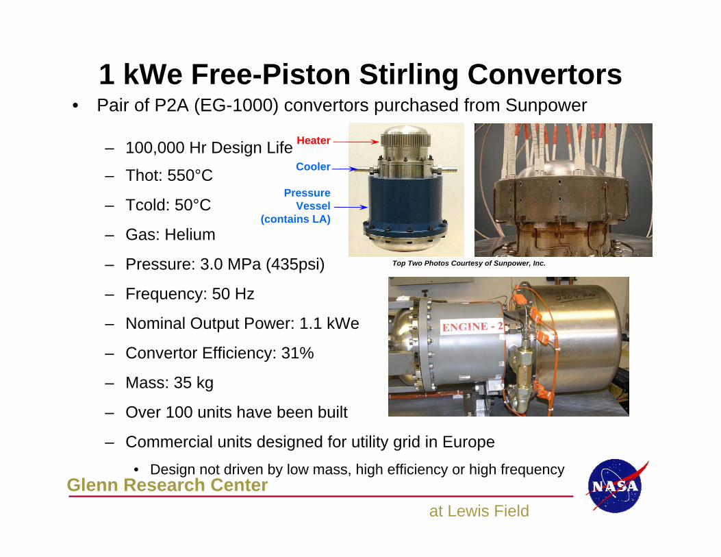
1 kWe Free-Piston Stirling Convertors• Pair of P2A (EG-1000) convertors purchased from Sunpower
– 100,000 Hr Design Life
– Thot: 550°C
– Tcold: 50°C
– Gas: Helium
– Pressure: 3.0 MPa (435psi)
– Frequency: 50 Hz
– Nominal Output Power: 1.1 kWe
– Convertor Efficiency: 31%
– Mass: 35 kg
– Over 100 units have been built
– Commercial units designed for utility grid in Europe• Design not driven by low mass, high efficiency or high frequency
Top Two Photos Courtesy of Sunpower, Inc.
Heater
Cooler
PressureVessel
(contains LA)
Glenn Research Centerat Lewis Field
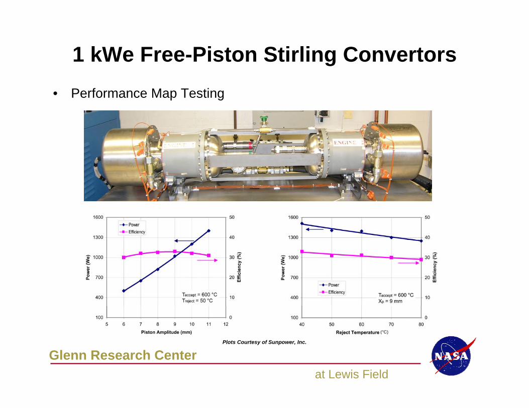
1 kWe Free-Piston Stirling Convertors• Performance Map Testing
Plots Courtesy of Sunpower, Inc.
Glenn Research Centerat Lewis Field
1 kWe Free-Piston Stirling Convertors
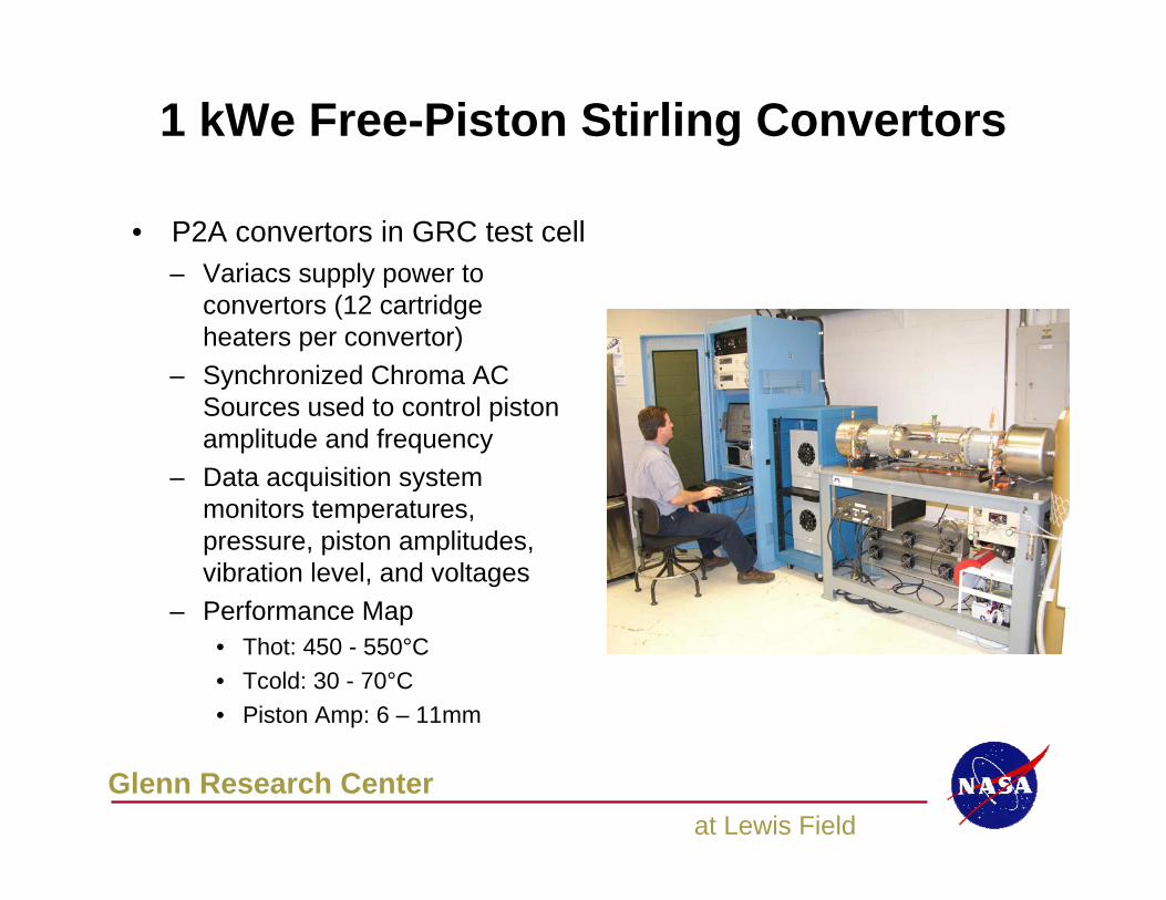
– Variacs supply power to convertors (12 cartridge heaters per convertor)
– Synchronized Chroma AC Sources used to control piston amplitude and frequency
– Data acquisition system monitors temperatures, pressure, piston amplitudes, vibration level, and voltages
– Performance Map• Thot: 450 - 550°C• Tcold: 30 - 70°C• Piston Amp: 6 – 11mm
• P2A convertors in GRC test cell
Glenn Research Centerat Lewis Field
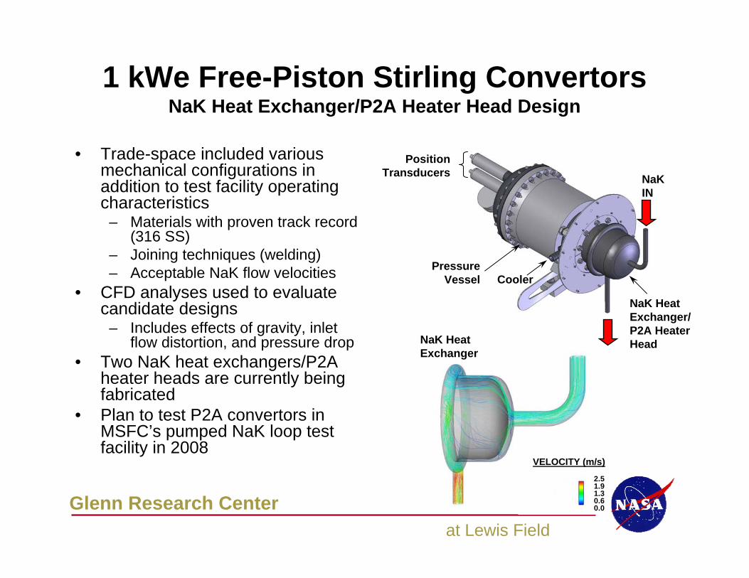
1 kWe Free-Piston Stirling ConvertorsNaK Heat Exchanger/P2A Heater Head Design
Position Transducers NaK
IN
NaK Heat Exchanger/P2A Heater Head
Pressure Vessel Cooler
2.51.91.30.60.0
VELOCITY (m/s)
• Trade-space included various mechanical configurations in addition to test facility operating characteristics
– Materials with proven track record (316 SS)
– Joining techniques (welding)– Acceptable NaK flow velocities
• CFD analyses used to evaluate candidate designs
– Includes effects of gravity, inlet flow distortion, and pressure drop
• Two NaK heat exchangers/P2A heater heads are currently being fabricated
• Plan to test P2A convertors in MSFC’s pumped NaK loop test facility in 2008
NaK Heat Exchanger
Glenn Research Centerat Lewis Field
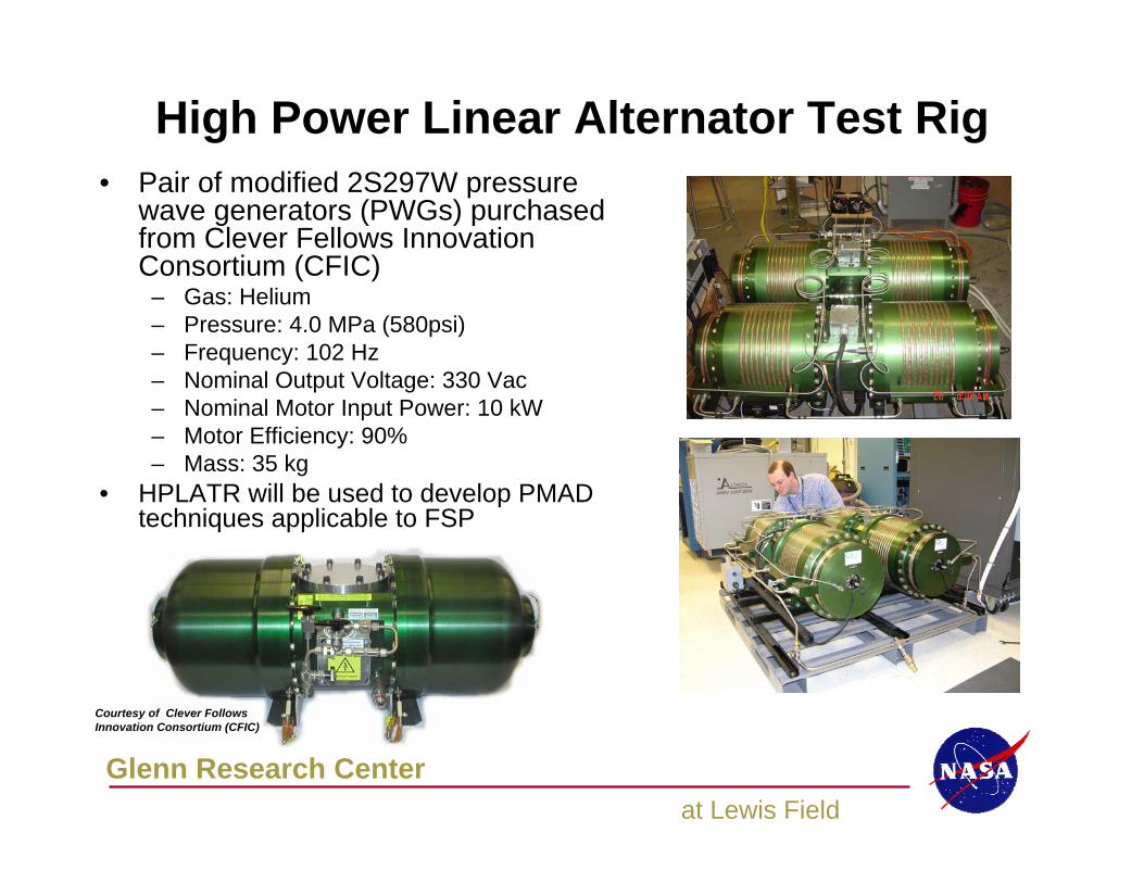
High Power Linear Alternator Test Rig• Pair of modified 2S297W pressure
wave generators (PWGs) purchased from Clever Fellows Innovation Consortium (CFIC)
– Gas: Helium– Pressure: 4.0 MPa (580psi)– Frequency: 102 Hz– Nominal Output Voltage: 330 Vac– Nominal Motor Input Power: 10 kW– Motor Efficiency: 90%– Mass: 35 kg
• HPLATR will be used to develop PMAD techniques applicable to FSP
Courtesy of Clever Follows Innovation Consortium (CFIC)
Glenn Research Centerat Lewis Field
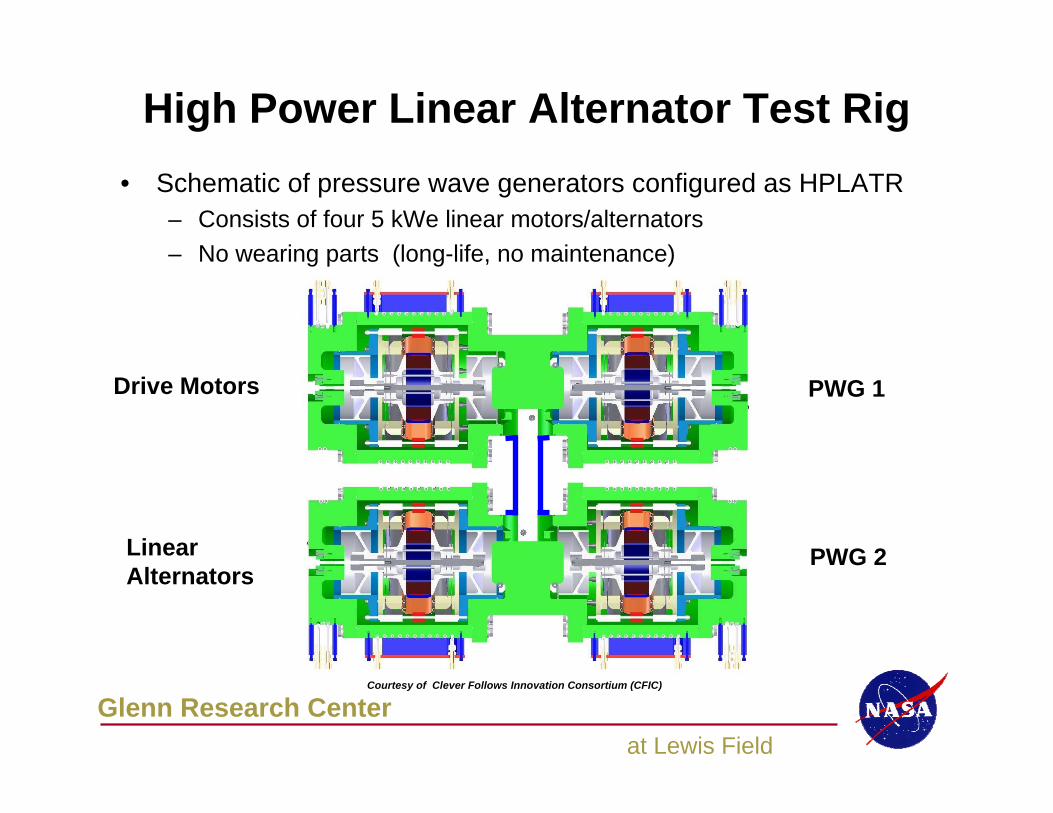
High Power Linear Alternator Test Rig
Drive Motors
Linear Alternators
PWG 1
PWG 2
• Schematic of pressure wave generators configured as HPLATR– Consists of four 5 kWe linear motors/alternators– No wearing parts (long-life, no maintenance)
Courtesy of Clever Follows Innovation Consortium (CFIC)
Glenn Research Centerat Lewis Field
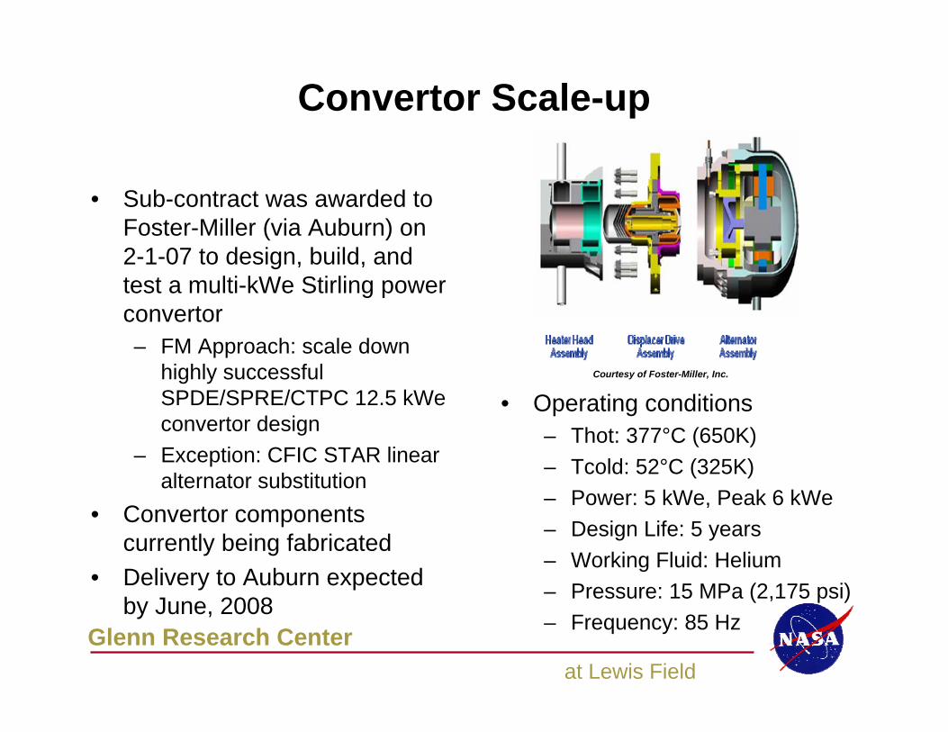
Convertor Scale-up
• Operating conditions– Thot: 377°C (650K)– Tcold: 52°C (325K)– Power: 5 kWe, Peak 6 kWe– Design Life: 5 years– Working Fluid: Helium– Pressure: 15 MPa (2,175 psi)– Frequency: 85 Hz
• Sub-contract was awarded to Foster-Miller (via Auburn) on 2-1-07 to design, build, and test a multi-kWe Stirling power convertor– FM Approach: scale down
highly successful SPDE/SPRE/CTPC 12.5 kWe convertor design
– Exception: CFIC STAR linear alternator substitution
• Convertor components currently being fabricated
• Delivery to Auburn expected by June, 2008
Courtesy of Foster-Miller, Inc.
Glenn Research Centerat Lewis Field
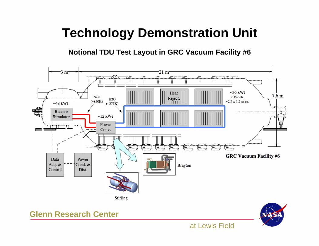
Technology Demonstration UnitNotional TDU Test Layout in GRC Vacuum Facility #6
Glenn Research Centerat Lewis Field
Concluding Remarks
• A pair of 1 kWe free-piston Stirling convertors are being readied for performance map testing
• Two NaK heat exchanger/heater heads are being fabricated
• The NaK heat exchanger/heater heads will be installed on the 1 kWe Stirling convertors, then tested in the MSFC pumped NaK looptest facility later this year
• The HPLATR is being readied for operation to aid the developmentof PMAD techniques for surface power applications
• Stirling technology is a viable option for FSP applications
Glenn Research Centerat Lewis Field
Acknowledgments
• Malcolm Robbie of the Analex Corp developed the mechanical design of the NaK heat exchanger.
• The authors wish to thank Sunpower Inc., Clever Fellows Innovation Consortium (CFIC) Inc., Auburn Space Research Institute, and Foster-Miller for contributing some of the information contained in this presentation.
• The work described in this presentation was performed for the Fission Surface Power Project within the Exploration Technology Development Program under the NASA Exploration Systems Mission Directorate. Any opinions expressed are those of the authors and do not necessarily reflect the views of the Exploration Systems Mission Directorate.