Embed Size (px)
Citation preview
NASA/TM--2001-211132 IECEC2001-CT-38
CFD Modeling of Free-Piston Stirling Engines
Mounir B. Ibrahim
Cleveland State University, Cleveland, Ohio
Roy C. Tew, Jr.
Glenn Research Center, Cleveland, Ohio
Zhiguo Zhang
Cleveland State University, Cleveland, Ohio
David Gedeon
Gedeon Associates, Athens, Ohio
Terrence W. Simon
University of Minnesota, Minneapolis, Minnesota
Prepared for the
36th Intersociety Energy Conversion Engineering Conference
cosponsored by the ASME, IEEE, AIChE, ANS, SAE, and AIAA
Savannah, Georgia, July 29-August 2, 2001
National Aeronautics and
Space Administration
Glenn Research Center
September 2001
https://ntrs.nasa.gov/search.jsp?R=20020009016 2020-03-10T12:15:11+00:00Z
Acknowledgments
This work was conducted under a NASA Grant to Cleveland State University, NAG3-2482. Professor Ibrahim,
Cleveland State University, Professor Simon, University of Minnesota, and David Gedeon, Gedeon Associates,
are Co-Principle Investigators. The Thermo-Mechanical Branch, Power and On-Board Propulsion
Division, NASA Glenn Research Center, under the leadership of Mr. Richard Shaltens,
Branch Chief, is greatly acknowledged.
This report is a formal draft or working
paper, intended to solicit comments and
ideas from a technical peer group.
This report contains preliminary
findings, subject to revision as
analysis proceeds.
Trade names or manufacturers' names are used in this report for
identification only. This usage does not constitute an officialendorsement, either expressed or implied, by the National
Aeronautics and Space Administration.
NASA Center for Aerospace Information7121 Standard Drive
Hanover, MD 21076
Available from
National Technical Information Service
5285 Port Royal Road
Springfield, VA 22100
Available electronically at http://gltrs._c.nasa.gov/GLTRS
CFD MODELING OF FREE-PISTON STIRLING ENGINES
Mounir B. Ibrahim
Cleveland State University
Cleveland, Ohio 44115
Roy C. Tew, Jr.National Aeronautics and Space Administration
Glenn Research CenterCleveland, Ohio 44135
Zhiguo ZhangCleveland State University
Cleveland, Ohio 44115
David Gedeon
Gedeon AssociatesAthens, Ohio 45701
Terrence W. Simon
University of MinnesotaMinneapolis, Minnesota 55455
ABSTRACT
NASA Glenn Research Center (GRC) is funding ClevelandState University (CSU) to develop a reliable ComputationalFluid Dynamics (CFD) code that can predict engine
performance with the goal of significant improvements inaccuracy when compared to one-dimensional (l-D) designcode predictions. The funding also includes conducting codevalidation experiments at both the University of Minnesota(UMN) and CSU. In this paper a brief description of the work-in-progress is provided in the two areas (CFD & Experiments).Also, previous test results are compared with computational
data obtained using: 1) a 2-D CFD code obtained from Dr.Georg Scheuerer and further developed at CSU and 2) a multi-dimensional commercial code CFD-ACE+. The test data and
computational results are for: 1) a gas spring and 2) a singlepiston/cylinder with attached annular heat exchanger. The
comparisons among the codes are discussed. The paper alsodiscusses plans for conducting code validation experiments atCSU & UMN.
INTRODUCTION
The type of flows that are normally encountered in StirlingEngines are: 1) Unsteady (Oscillatory Flow/ OscillatoryPressure), 2) 2-D/3-D Flows (Complex Geometry), 3)Compressible (low Mach Number), Laminar�Transition�Turbulent, 4) Unsteady Conduction/Convection Heat Transfer,
5) Sudden changes in cross-section, 6) Isothermal/adiabaticboundary conditions, and 7) Single phase with no chemicalreaction. On the other hand the losses encountered in Stirlingengines (Tew 1988 & Tew and Geng 1992) are: 1) Gas springand working space hysteresis losses, 2) Gas-to-heat exchanger
heat transfer inefficiencies, 3) Viscous (pressure drop) losses,4) Appendix gap losses (shuttle and pumping), 5) Mixing lossesdue to mixing of gases at different temperatures, 6) Conductionlosses from the hot- to the cold-end of the engine. In addition,there are losses due to differences in flow distribution: a) fromone heat exchanger flow passage to the other and/or b) acrossthe regenerator (1-D codes assume uniform flow).
A successful CFD code that simulates the engineadequately should capture the characteristics of the flow and
the type of losses described above.
Stirlin,q One-Dimensional CodesDuring the late 70's and early 80's, NASA developed it's
own finite-difference Stirling engine performance code for use inmonitoring the work of its Stirling engine contractors (Tew, et.a1.1978 & Tew 1983). Later NASA gained unlimited rights to theMT/ developed HFAST (Huang 1993) harmonic code, via acontract with MTI. NASA also purchased the GLIMPS Stirlingengine code from David Gedeon. GLIMPS (now developed into
Sage, Gedeon 1995) has been the primary design tool used bythe Stirling Technology Co. (STC) in recent years. HFAST andGLIMPS (now Sage) were both more time-efficient and user-friendly than the NASA's finite-difference code; and they wereboth being used to design real hardware.
Tew and Geng,1992 showed comparisons of the lossescalculated by GLIMPS and HFAST for the 12.5 kWe
Component Test Power Converter (CTPC). Although the overallengine power and efficiency predictions were quite close, therewere substantial differences in some of the loss calculations.
For example GLIMPS calculations suggested that cylinderhysteresis power losses were about 10% of the indicated powerwhile HFAST calculated a much smaller value (-3%) for this
loss. HFAST predicted larger viscous and mixing losses thanGLIMPS, and so the overall engine performance predictionswere similar. Geng and Tew, 1992 showed additionalHFAST/GLIMPS comparisons, both "calibrated" and"uncalibrated", for the 1.2 kW indicated power RE-1000 engineand the 14 kW indicated power Space Power DemonstratorEngine (SPDE). GLIMPS also calculated that cylinder
hysteresis losses were about 10% of the indicated power forthese engines.
The Sage commercial code (Gedeon 1995) was introducedabout six years ago. The Sage Stirling-cycle modeling softwareis the latest in a line of commercial software developed byGedeon Associates. It is a direct descendant of the GLIMPS
software, which was used widely within the Stirling industry fornearly ten years. Sage introduced a drag-and-drop visualinterface where a user could assemble complete machines fromstandard components, such as pistons, cylinders, heat-exchangers, etc. Sage also introduced an interactiveoptimization capability built into the visual interface.
NASA/TM--2001-211132 l
CAST and Modified CAST Code
A CFD code, CAST, received by Dr. Mounir Ibrahim from
Dr. Georg Scheuerer, was developed by Peric and Scheuerer1989. CAST, an acronym for Computer Aided Simulation ofTurbulent Flows, is a computer program which uses the finite
volume method for predicting two-dimensional flow and heattransfer phenomena. The CAST code is written in FORTRANIV. CAST is similar in structure to existing fluid flow predictionprocedures like TEACH (Gosman and Ideriah, 1978) and TEAM(Huang and Lewchziner, 1983); it differs from those codes inthe following ways (1) it has a co-located variable arrangement,
(2) it has a different discretization scheme, (3) the solutionalgorithms are different for the linear equation systems arisingfrom the discretization, and (4) the pressure-velocity coupling isadapted to the co-located variable storage. CAST solves theNavier-Stokes equations, For turbulent flows, the Reynolds-
averaged Navier-Stokes equations are solved in connectionwith the k-£, two-equation turbulence model of Launder and
Spalding.The CAST code was used by several Cleveland State
University (CSU) graduate students working under the directionof Dr. Mounir Ibrahim for two-dimensional modeling of "Stirlingmachine like" components. This work was conducted under
grants from NASA Glenn Research Center (which was NASALewis at the time of the work) in the period from 1989 to1994.
Below is a summary of the code development topics:1) Oscillating inlet & outlet velocity conditions, 2) Suddenchange in channel cross section, i.e. sudden expansion in onehalf of the cycle and sudden contraction in the other half, 3)
Different Low-Reynolds Number, k-_, turbulent models, 4) Amodel for laminar-transition-turbulent in a pipe flow, 5)Incompressible-flow with moving boundaries and, finally, 6)
Compressible-flow with moving boundaries.This work is summarized below:
Ahn 1992, added a low-Reynolds-Number k-_ turbulence modelto CAST for purposes of conducting studies of laminar toturbulent transition in pipe flows. This modified CAST code wasused in cooperation with experimental studies at the Universityof Minnesota to help determine that upon relaminarization ofturbulent pipe flow over a periodic cycle, the laminar flow at the
beginning of the new cycle had attained the characteristics of asteady, uniform velocity distribution (in the radial direction).
Hashim, 1992, configured the CAST code to simulateoscillating flow and heat transfer in parallel-plate channels witha sudden change in cross-section. The flow was assumed tobe laminar and incompressible with the inflow velocity uniformover the channel cross-section but varying sinusoidally with
time. Ibrahim et. al., 1992, using the computational results,were able to determine instantaneous friction factors and heat
transfer coefficients for laminar oscillating flow between parallelplates with a sudden change in cross-section. It was found thatinstantaneous friction factors and heat transfer coefficients
deviated substantially from the steady-state values for the samedimensionless flow parameters.
Kannapareddy, 1993, used CAST to model laminar,incompressible, oscillatory flow in the heater, regenerator andcooler of the NASA Stirling Space Power Research Engine(SPRE). The heater and cooler tubes were modeled as circularpipes with isothermal walls; the regenerator was modeled as
two-parallel plates. Although the flow was oscillatory, when theflow was into the heater or cooler, the input temperatures wereassumed to be constant. The study was carried out for a widerange of Maximum Reynolds numbers (based on maximum flow
velocity), Valensi numbers (non-dimensional frequencies), andrelative amplitudes of fluid displacement in the component ofinterest; the ranges chosen were based on the operatingranges of the NASA SPRE. The instantaneous friction factor,wall heat flux and heat transfer coefficient were examined. Itwas concluded that the friction factor and heat transfer
coefficients are larger under oscillatory flow conditions for largerValensi numbers (i.e., larger non-dimensional frequencies).Also the thermal efficiency of the heat exchangers decreasedfor the lower fluid displacement values and the steady-statedefinition for the heat transfer coefficient did not appear valid for
use with oscillatory-flow ranges studied. A concise presentationof this work was reported by Ibrahim and Kannapareddy, 1992.In work that was not documented, Kannapareddy modifiedCAST to incorporate a moving boundary model to allowsimulation of piston motion. These modifications were based
upon information in Ferziger and Peric, 1997.Bauer, 1993, used CAST with the low-Reynolds number
k-_, turbulence model option (Lam-Bremhorst form), to assistIbrahim et al., 1994, in developing an empirical transition modelthat could be used to predict when in the University ofMinnesota (UMN) periodic-pipe-flow experiments (Qiu andSimon, 1994) transition laminar to turbulent flow would occur.
The empirical transition model was used to activate theturbulence model at the appropriate time within the cycle for agiven axial location in the tube. This analytical technique formodeling unsteady flow and heat transfer in Stirling engineheater and cooler tubes (Simon, et al. 1992, and Ibrahim, et al.,1994) is now an essential component of the 1-D systemsimulation code Sage (at that time called GLIMPS). The testsused for this development showed important features of
oscillatory flow, which led to enhanced understanding of themechanisms for losses in Stirling systems. Such featuresinclude transition from the laminar flow to turbulence in each
cycle of oscillation and the rapid dissipation of the turbulence,which remains from one cycle as a result of the extremelystrong axial straining of the fluid upon temporal acceleration atthe beginning of the following cycle. This collaborative effort
showed the value of combining computational results withexperimental finding for better understanding of Stirling engineflow and heat transfer processes,
In searching for a compressible flow simulation techniquessuitable for simulation of Stirling machines, the literature wasfirst searched for papers relating to "low Mach number
compressible flow." Many such papers were obtained. Forexample, papers by Pletcher and Chen, 1993, Chert andPletcher, 1991, Sesterhenn, Muller et a1.1993, Turkel, 1987,
Weiss and Smith, 1993, and Horibata, 1992 were reviewed.These papers appeared to take the approach of starting with afully compressible model (including acoustics) and making
suitable modifications to the solution technique so that thecalculations could be extended to low Mach number flow. If anyof these approaches had been taken to modify the CAST code,it appeared that it would be almost equivalent to starting overand developing a new code. And, these approaches did notappear to offer the time benefits that could be achieved bycomplete elimination of acoustic phenomena.
For all practical Stifling engines with which these authorshave familiarity, flow occurs at very low Mach numbers (usuallymuch less than 0.1). However, compressibility is very importantbecause volume changes due to piston motion in an enclosedvolume produce large changes in the engine pressure level anddensity over the cycle. Due to the compact nature of Stirling
NASA/TM--2001-211132 2
machines and the moderate frequencies of operation
(< 125 Hz), spatial pressure variations at any given time arerelatively small so that spatial density variations are due almost
entirely to spatial temperature variations. Calculations haveshown that it appears to be a good approximation to assumethat the speed of sound is infinitely fast inside most Stirlingmachines. Some authors, such as Organ, 1992, appear to
contest this assumptionThe literature search continued for a compressible flow
approach based on the assumption that acoustics arenegligible. An excellent paper explaining such an approachwas found in the 1997 Journal of Fluid Mechanics entitled "A
model of unsteady subsonic flow with acoustics excluded" byA.T. Fedorchenko, 1997. The derivations include a set of
equations for simulating subsonic flow of a heat-conducting,viscous gas. The simplifications in the Navier-Stokes equationsused to eliminate acoustics include: (1) Pressure at any time
and spatial location is split into a mean pressure level thatvaries only with time and a delta-pressure relative to areference location that varies with spatial position and time; (2)
The pressure appearing in the equation of state (for example,the ideal gas equation of state) is the mean pressure that variesonly with time. Therefore, from the equation of state, density is
a function only of the mean pressure level and the temperature(which varies with spatial position and time); and (3) Thepressure appearing in the momentum equations is just thedelta-pressure relative to the reference location.
Thus, Fedorchenko's paper provided the basis for
modifying the CAST code. A technique from an early finite-difference one-dimensional flow non-acoustic code (Tew,Jefferies and Miao, 1978, Taw, 1983) was incorporated toensure an accurate mass balance. It was not necessary to
modify the incompressible form of the SIMPLE algorithm usedin CAST since density does not vary with the delta-pressurefrom the reference location. More details are available in (Tew &
Ibrahim, 2001)The modified CAST can now be used to simulate: (1) fixed-
boundary, incompressible flow with an inlet and an outletboundary, (2) incompressible flow with a moving boundary(piston, for example) with one inlet/outlet, or (3) compressible,non-acoustic, flow in a completely enclosed volume with a
moving boundary.
CFD-ACE÷ CodeCFD-ACE+ is a commercial CFD code product of CFD
Research Corporation. It is a set of computer programs formulti-physics computational analysis. The programs provide an
integrated geometry and grid generation module, a graphicaluser interface for preparation of the model, a computational
solver for performing the simulation, and an interactivevisualization program for examination and analysis of thesimulation results. The standard CFD-ACE+ package includes
the following applications: geometry and grid generation,
advanced polyhedral solver and a post processor.CFD-ACE+ has been used for design and analysis of a
wide variety of industrial applications. It can model 2-D or 3-Dgeometries and includes acoustics.
ANALYSIS
For this paper analyses were performed using CFD-ACE+and the Modified CAST code for gas spring and
piston/cylinder/heat exchanger (or two-space) cases (SeeAppendix A for test rig dimensions originating from Kornhauser,
1989):(1) Gas Spring case: The computational domain is 2-D andaxisymmetric, with minimum dimensions of 0.0762 (x-direction)*0.0254(m) Piston stroke is 0.0762 m. Also 86*40 grids and200 time-steps/cycle were used.
(2) Two-space case: The computational domain is 2-D andaxisymmetric, with dimensions of -0.445 (x-direction)*0.0254(m). The piston stroke was also 0.0762 m for this case.148"48 grids and 960 time-steps/cycle were used.Helium was used as the working fluid, with the standard k-e,
turbulence model and upwind finite differencing scheme.
RESULTS
Gas Sprinq Hysteresis LossesFor a gas spring, the hysteresis loss is the work that is
dissipated by the spring per cycle at steady operatingconditions; it's also equal to the heat generated in andtransferred out of the spring. A good way to compare
computational and measured hysteresis losses is via plots ofdimensionless work as a function of oscillating flow Pecletnumber. Dimensionless work and oscillating flow Peclet
numbers are defined, respectively, as follows:
_PdV_l)oss ( 1 )-fl flPolo _ _,-i
kPo) k Y )
Pe¢o = P°cp°2D_ ( 2 )
4A
Where:
Cp specific heat at constant pressure,
Dh hydraulic diameter (=4 x wetted area/wetted perimeter),
P mean spatial pressure,
Pa amplitude of mean spatial pressure
Po arithmetic mean of max. and min. mean spatial pressures
V volume
_o arithmetic mean of maximum and minimum volumes
l_'loss non-dimensional work or hysteresis loss
Greek letters
? ratio of specific heats of fluid
/1. molecular thermal conductivity
p density, fluid mass per unit volume
co angular velocity (tad/sac)
NASA/TM--2001-211132 3
@,.i
10
_D
o 0.1'W
,_Eo
<)Modified CAST (Tew & Ibrahim 2001)I
a CFD-ACE+ - Present Work L
• Reck'tenwald (1989) I
× Kornhauser (1989)
INn:'ie : ::"::: :::::: : : :::::: : : :::::
: : ::::::
i i i ii.:iii i i iiiii; : : :::::: : : :::::: : : :::::
: : ::::::
0.01 ....... :
0.1 1 10 100 1000 10000
Oscillating Peclet Number, Pe
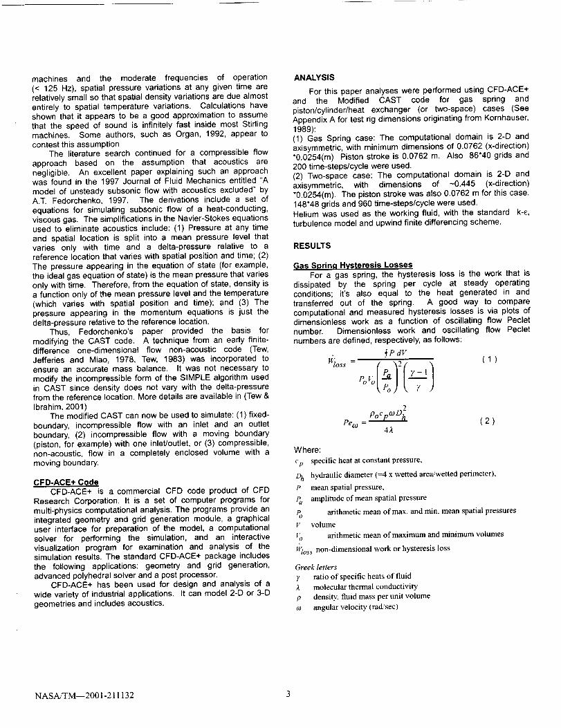
Figure 1: Comparison Among CFD Codes forDimensionless Losses & Kornhauser's (1989)Experimentally Derived Losses.
Figure 1 shows the dimensionless work plotted versus thePeclet number for the computations of CFD-ACE+, ModifiedCAST and Recktenwald (1989) together with Kornhauser's(1989) data. Only four data points were chosen for CFD-ACE+over a range of Pe from 0.97 to 843. The CFD-ACE+predictions fit very well with all the other results presented inFigure 1. More detailed comparisons between thecomputational results and experimental data are given in acompanion paper (Tew and Ibrahim 2001).
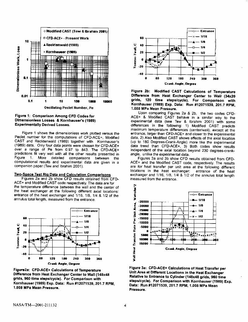
Two-Space Test Rig Data and Calculation ComparisonsFigures 2a and 2b show CFD results obtained from CFD-
ACE+ and Modified CAST code respectively. The data are forthe temperature difference between the wall and the center ofthe heat exchanger at the following different axial locations:entrance of the heat exchanger and 1/16, 1/8, 1/4 & 1/2 of theannulus total length, measured from the entrance.
GO
4O
_" ZO _x_x
i °_ -20
-40
O 60 120 180
Crank Angle. Degree
Figure2a: CFD-ACE+ Calculations of TemperatureDifference from Heat Exchanger Center to Wall (148x48grids, 960 time steps/cycle). For Comparison with
Kornhauser (1989) Exp. Data: Run #12071539, 201.7 RPM,1.008 MPa Mean Pressure.
Entrance
--x-- l/IS
_-- 118
@ li4
-.--l-- hl2
,W41"i i
240 300 380
GO
U 40
• 20)-
ev.
® 0
@
I,_ -20
-4O
GO 120 180
----O'-- Entrance +
--x-- lllG
---•-- 1t8
1/4
---41-- !!2
+
r-"r240 300 380
Crank Angle, Deglee
Figure 2b: Modified CAST Calculations of TemperatureDifference from Heat Exchanger Center to Wall (34x20grids, 120 time steps/cycle). For Comparison withKornhauser (1989) Exp. Data: Run #12071539, 201.7 RPM,1.008 MPa Mean Pressure.
Upon comparing Figures 2a & 2b, the two codes CFD-ACE+ & Modified CAST behave in a similar way to theexperimental data (see Tew & Ibrahim 2001) with somedifferences in the following: 1) Modified CAST predictsmaximum temperature differences (center/wall), except at theentrance, larger than CFD-ACE+ and closer to the experimentaldata, 2) Also Modified CAST shows effects of the axial location(up to 180 Degrees-Crank-Angle) more like the experimentaldata trend than CFD-ACE+, 3) Both codes show resultsindependent of the axial location beyond 230 degrees-crank-angle, unlike the experimental data.
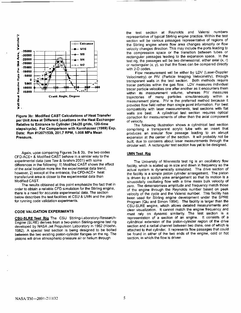
Figures 3a and 3b show CFD results obtained from CFD-ACE+ and the Modified CAST code, respectively. The resultsare for heat transfer per unit area at the following differentlocations in the heat exchanger: entrance of the heatexchanger and 1/16, 1/8, 1/4 & 1/2 of the annulus total lengthmeasured from the entrance.
)• -35000
-30000-25000
-20000
-15000-I0000-5000
0
sooo= I0000
2 asooo
6
Z
>
[
J
Entrance
1/16
--e- 118
'--,dk'---1t4--:_-- I/2
\
r'k .._ ,ll,,irll I,_A .,'_+im, .,Jllml +i,
Crank Angle. Degree
Figure 3a: CFD-ACE+ Calculations of Heat Transfer perUnit Area at Different Locations in the Heat ExchangerRelative to Entrance to Cylinder (148x48 grids, 960 time
steps/cycle). For Comparison with Kornhauser (1989) Exp.Data: Run #12071539, 201.7 RPM, 1.008 MPa MeanPressure.
NASA/TM--2001-211132 4
'i
)• -35000
-30000-25000
-20000
-15000-10000
-5ooo
o
5000¢ !oooo
15ooo
@
zZ
>.
Entrance ]---II-- I/1G
---Am 114--_-- 1,2 I i
Crank. Angle. Degree
Figure 3b: Modified CAST Calculations of Heat Transfer
per Unit Area at Different Locations in the Heat ExchangerRelative to Entrance to Cylinder (34x20 grids, 120-time
steps/cycle). For Comparison with Kornhauser (1989) Exp.Data: Run #12071539, 201.7 RPM, 1.008 MPa Mean
Pressure.
Again, upon comparing Figures 3a & 3b, the two codesCFD-ACE+ & Modified CAST behave in a similar way to the
experimental data (see Tew & Ibrahim 2001) with somedifferences in the following: 1) Modified CAST shows the effectof the axial location more like the experimental data trend,
however, 2) except at the entrance, the CFD-ACE+ heattransfer/unit area is closer to the experimental data thanModified CAST.
The results obtained at this point emphasize the fact that inorder to obtain a reliable CFD simulation for the Stirling engine,
there is a need for accurate experimental data. The sectionbelow describes the test facilities at CSU & UMN and the plan
for running code validation experiments.
CODE VALIDATION EXPERIMENTS
CSU-SLRETest Rig The CSU Stirling-Laboratory-Research-
Engine (SLRE) derives from a two-piston Stirling-engine test rigdeveloped by NASA Jet Propulsion Laboratory in 1982 (Hoehn,1982). A special test section is being designed to be boltedbetween the two existing piston-cylinder flanges on the rig. The
pistons will drive atmospheric-pressure air or helium through
the test section at Reynolds and Valensi numbers
representative of typical Stirling engine practice. Within the testsection will be various passages representative of regions of
the Stirling engine where flow area changes abruptly or flow
velocity changes direction. This may include the ports leading tothe compression space or the transition between tubes orrectangular passages leading to the expansion space. In thetest rig, the passages will be two dimensional, either axial (x, r)or rectangular (x, y), so that the flows can be compared directlywith 2-D codes.
Flow measurement will be either by LDV (Laser-Doppler
Velocimetry) or PIV (Particle Imaging Velocimetry), throughtransparent walls in the test section. Both methods requiretracer particles within the gas flow. LDV measures individualtracer particle velocities one after another as it encounters themwithin its measurement volume, whereas PIV measures
trajectories of many particles simultaneously within ameasurement plane. PIV is the preferred method because it
provides flow field rather than single point information. For bestcompatibility with laser measurements, test sections with flatwalls are best. A cylindrical test section requires opticalcorrection for measurements of other than the axial component
of velocity.The following illustration shows a cylindrical test section
comprising a transparent acrylic tube with an insert that
produces an annular flow passage leading to an abruptexpansion at the center of the section. It will probably not bebuilt, due to concerns about laser measurements through the
circular wall. A rectangular test section has yet to be designed.
UMNTest Rig
The University of Minnesota test rig is an oscillatory flow
facility, which is scaled up in size and down in frequency so theactual system is dynamically simulated. The drive section of
the facility is a simple piston cylinder arrangement. The pistonis driven by a scotch yoke arrangement so that its motion is asinusoidally oscillating flow with a time mean bulk velocity ofzero. The dimensionless amplitude and frequency match thoseof the engine through the Reynolds number based on peak
velocity of the cycle and the Valensi number. This facility hasbeen used for Stirling engine development under the SPRE
Program (Qiu and Simon 1994). The facility is larger than theCSU-SLRE engine, which allows detailed measurements andclear visualization. It cannot match the engine frequency and
must rely on dynamic similarity. The test section is arepresentation of a section of an engine. It consists of a
cylindrical extension of the piston-cylinder region of the drivesection and a radial channel between two disks, one of which is
attached to that cylinder. It represents flow passages that couldbe found in either of the two ends of the engine, cold or hot
section, in which the flow is driven
NASA/TM--2001-211132 5
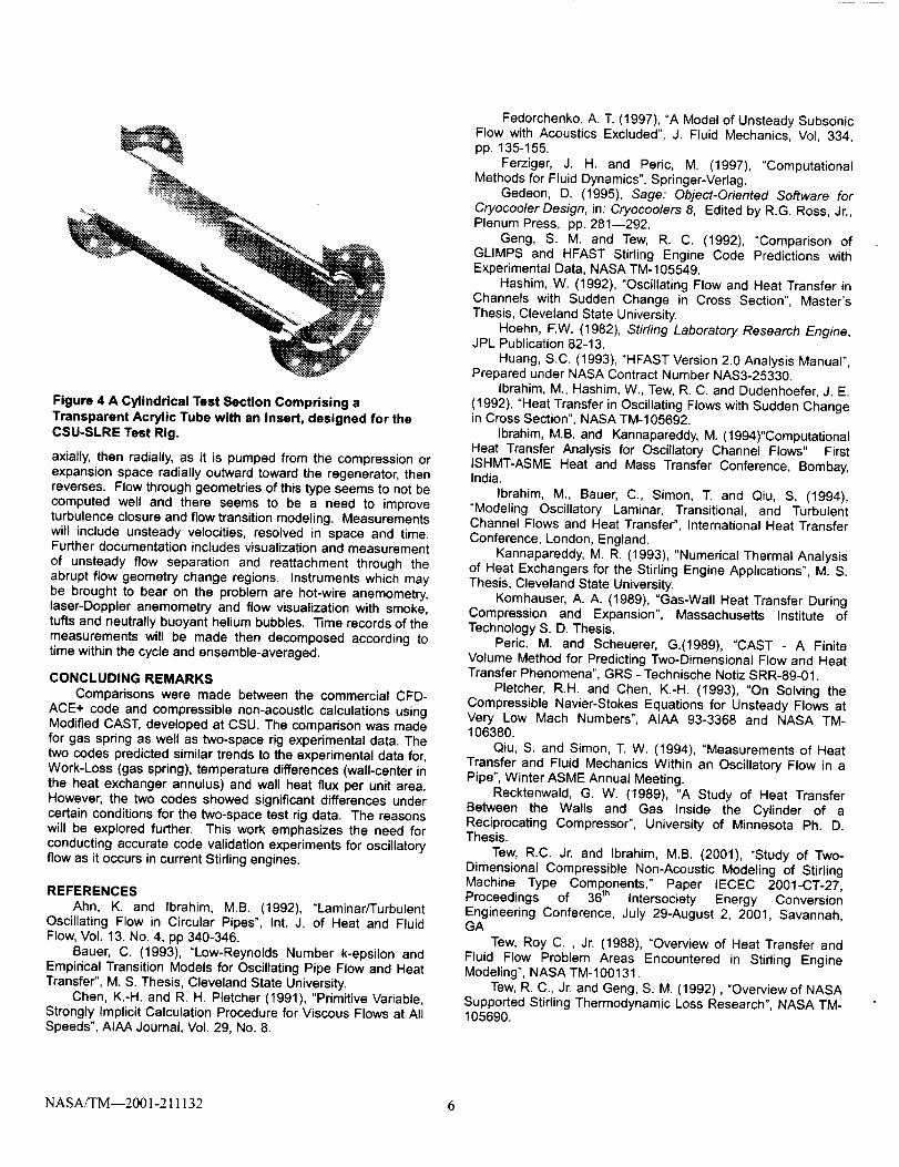
Figure 4 A Cylindrical Test Section Comprising a
Transparent Acrylic Tube with an Insert, designed for the
CSU-SLRE Test Rig.
axially, then radially, as it is pumped from the compression orexpansion space radially outward toward the regenerator, then
reverses. Flow through geometries of this type seems to not becomputed well and there seems to be a need to improveturbulence closure and flow transition modeling. Measurementswill include unsteady velocities, resolved in space and time.Further documentation includes visualization and measurement
of unsteady flow separation and reattachment through theabrupt flow geometry change regions. Instruments which may
be brought to bear on the problem are hot-wire anemometry,laser-Doppler anemometry and flow visualization with smoke,tufts and neutrally buoyant helium bubbles. Time records of themeasurements will be made then decomposed according totime within the cycle and ensemble-averaged.
CONCLUDING REMARKS
Comparisons were made between the commercial CFD-ACE+ code and compressible non-acoustic calculations usingModified CAST, developed at CSU. The comparison was made
for gas spring as well as two-space rig experimental data. Thetwo codes predicted similar trends to the experimental data for,Work-Loss (gas spring), temperature differences (wall-center inthe heat exchanger annulus) and wall heat flux per unit area.However, the two codes showed significant differences undercertain conditions for the two-space test rig data. The reasons
will be explored further. This work emphasizes the need forconducting accurate code validation experiments for oscillatoryflow as it occurs in current Stifling engines.
REFERENCES
Ahn, K. and Ibrahim, M.B. (1992), "Laminar/Turbulent
Oscillating Flow in Circular Pipes", Int. J. of Heat and FluidFlow, Vol. 13, No. 4, pp 340-346.
Bauer, C. (1993), "Low-Reynolds Number k-epsilon andEmpirical Transition Models for Oscillating Pipe Flow and HeatTransfer", M. S. Thesis, Cleveland State University.
Chen, K.-H. and R. H. Pletcher (1991), "Primitive Variable,Strongly Implicit Calculation Procedure for Viscous Flows at AllSpeeds", AIAA Journal, Vol. 29, No. 8.
Fedorchenko, A. T. (1997), "A Model of Unsteady SubsonicFlow with Acoustics Excluded", J. Fluid Mechanics, Vol, 334,pp. 135-155.
Ferziger, J. H. and Peric, M. (1997), "Computational
Methods for Fluid Dynamics", Springer-Verlag.Gedeon, D. (1995), Sage: Object-Oriented Software for
Cryocooler Design, in: Cryocoolers 8, Edited by R.G. Ross, Jr.,Plenum Press, pp. 281--292.
Geng, S. M. and Tew, R. C. (1992), "Comparison ofGLIMPS and HFAST Stifling Engine Code Predictions withExperimental Data, NASA TM-105549.
Hashim,.W. (1992), "Oscillating Flow and Heat Transfer inChannels with Sudden Change in Cross Section", Master'sThesis, Cleveland State University.
Hoehn, F.W. (1982), Stirling Laboratory Research Engine,JPL Publication 82-13.
Huang, S.C. (1993), "HFAST Version 2.0 Analysis Manual",Prepared under NASA Contract Number NAS3-25330.
Ibrahim, M., Hashim, W., Tew, R. C. and Dudenhoefer, J. E.
(1992), "Heat Transfer in Oscillating Flows with Sudden Changein Cross Section", NASA TM-105692.
Ibrahim, M.B. and Kannapareddy, M. (1994)"ComputationalHeat Transfer Analysis for Oscillatory Channel Flows" FirstISHMT-ASME Heat and Mass Transfer Conference, Bombay,India.
Ibrahim, M., Bauer, C., Simon, T. and Qiu, S. (1994),"Modeling Oscillatory Laminar, Transitional, and TurbulentChannel Flows and Heat Transfer", International Heat Transfer
Conference, London, England.Kannapareddy, M. R. (1993), "Numerical Thermal Analysis
of Heat Exchangers for the Stirling Engine Applications", M. S.Thesis, Cleveland State University.
Kornhauser, A. A. (1989), "Gas-Wall Heat Transfer DuringCompression and Expansion", Massachusetts Institute ofTechnology S. D. Thesis.
Peric, M. and Scheuerer, G.(1989), "CAST - A FiniteVolume Method for Predicting Two-Dimensional Flow and HeatTransfer Phenomena", GRS - Technische Notiz SRR-89-01.
Pletcher, R.H. and Chen, K.-H. (1993), "On Solving theCompressible Navier-Stokes Equations for Unsteady Flows atVery Low Mach Numbers", AIAA 93-3368 and NASA TM-106380.
Qiu, S. and Simon, T. W. (1994), "Measurements of HeatTransfer and Fluid Mechanics Within an Oscillatory Flow in a
Pipe", Winter ASME Annual Meeting.Recktenwald, G. W. (1989), "A Study of Heat Transfer
Between the Walls and Gas Inside the Cylinder of aReciprocating Compressor", University of Minnesota Ph. D.Thesis.
Tew, R.C. Jr. and Ibrahim, M.B. (2001), "Study of Two-
Dimensional Compressible Non-Acoustic Modeling of StirtingMachine Type Components," Paper IECEC 2001-CT-27,Proceedings of 36 th Intersociety Energy Conversion
Engineering Conference, July 29-August 2, 2001, Savannah,GA
Tew, Roy C. , Jr. (1988), "Overview of Heat Transfer andFluid Flow Problem Areas Encountered in Stirling Engine
Modeling", NASA TM-100131.Few, R. C., Jr. and Geng, S. M. (1992), "Overview of NASA
Supported Stirling Thermodynamic Loss Research", NASA TM°105690.
NASAJTM--2001-211132 6
Tew, R. C., Jr., Jefferies, K. and Miao, D. (1978), "A Stirling
Engine Computer Model for Performance Calculations",DOE/NASA/1011-78/24, NASA TM-78884.
Tew, Roy C. Jr. (1983), "Computer Program for Stirling
Engine Performance Calculations", DOE/NASA/51040-42,NASA TM-82960.
Sesterhenn, Jorn, et. al. (1993), "Flux-Vector Splitting forCompressible Low Mach Number Flow", Computes Fluids, Vol.
22, No. 4/5, pp. 441-451.
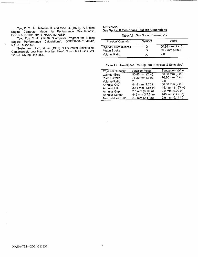
APPENDIX
Gas Spring & Two-Space Test Ri.q Dimensions
Table AI: Gas Spring Dimensions
Physical Quantity Symbol Value
Cylinder Bore (Diam.) D 50.80 mm (2 in.)
Piston Stroke S 76.2 mm (3 in.)
Volume Ratio rv 2.0
Table A2: Two-Space Test Rig Dim. (Physical & Simulated)
Physical Quantity Physical Value Simulation Value
Cylinder BorePiston StrokeVolume RatioAnnulus O.D.
Annulus I.D.
Annulus Gap
Annulus LengthMin Pist/Head Cir.
50.80 mm (2 in)
76.20 mm (3 in)2.0
44.5 mm (1.75 in)
39.4 mm (1.55 in)2.5 mm (0.10 in)445 mm (17.5 in)
2.9 mm/0.11 in /
50.80 mm (2 in)76.20 mm (3 in)2.0
50.80 mm (2 in)
46.4 mm (1.83 in)2.2 mm (0.09 in)445 mm (17.5 in)
2.9 mm I0.11 in /
NASA/TM--2001-211132 7
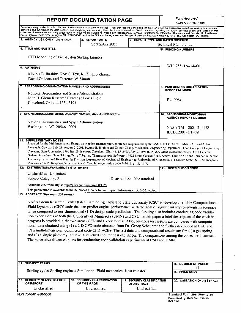
REPORT DOCUMENTATION PAGE FormApprovedOMB No. 0704-0188
Public reporting burden for this collection of information is estimated to average 1 hour per response, including the time for reviewing instructions, searching existing data sources,
gathering and maintaining the data needed, and completing and reviewing the collection of information. Send comments regarding this burden estimate or any other aspect of this
collection of information, including suggestions for reducing this burden, to Washington Headquarters Services, Directorate for Information Operations and Reports, 1215 Jefferson
Davis Highway, Suite 1204. Arlington, VA 22202-4302, and to the Office of Management end Budget, Paperwork Reduction Project (0704-0188), Washington, DC 20503.
1. AGENCY USE ONLY (Leave blank) 2. REPORT DATE
September 2001
4. TITLE AND SUBTITLE
CFD Modeling of Free-Piston Stirling Engines
6. AUTHOR(S)
Mounir B. Ibrahim, Roy C. Tew, Jr., Zhiguo Zhang,
David Gedeon, and Terrence W. Simon
! 7. PERFORMING ORGANIZATION NAME(S) AND ADDRESS(ES)
National Aeronautics and Space Administration
John H. Glenn Research Center at Lewis Field
Cleveland, Ohio 44135-3191
9. SPONSORING/MONITORING AGENCY NAME(S) AND ADDRESS(ES)
National Aeronautics and Space Administration
Washington, DC 20546-0001
3. REPORT TYPE AND DATES COVERED
Technical Memorandum
5. FUNDING NUMBERS
WU-755-1A-I 4-00
18. PERFORMING ORGANIZATION
REPORT NUMBER
E-12981
10. SPONSORING/MONITORINGAGENCY REPORT NUMBER
NASA TM--2001-211132
IECEC200I-CT-38
11. SUPPLEMENTARY NOTES
Prepared for the 36th Intersociety Energy Com,ersion Engineering Conference cosponsored by the ASME. IEEE, AIChE. ANS, SALE. and AIAA,
Savannah. Georgia, July 29-August 2, 2001. Mounir B. lbrahim and Zhiguo Zhang, Mechanical Engineering Department, Fenn College of Engineering.
Cleveland State University. 1960 East 24th Street. Cleveland, Ohio 44115-2425; Roy C. Tew, Jr., NASA Glenn Research Center; David Gedeon.
Gedeon Associates: Sage Stirling, Pulse Tube. and Thermoacoustic Software, 16922 South Canaan Road Athens, Ohio 45701: and Terrence W. Simon,
Thermodynanlics and Heat Transfer Division. Department of Mechanical Engineering. University of Minnesota, 111 Church Street, S.E.. Minneapolis,Minnesota 55455. Responsible pemon. Roy C. Tew. Jr.. organization code 5490. 216-433-8471.
12a. DISTRIBUTION/AVAILABILITY STATEMENT
Unclassified - Unlimited
Subject Category: 34 Distribution: Nonstandard
Available electronically at http://_ltrs.grc.nasa.gov/GLTRS
This publication is available from the NASA Center for AeroSpace Information, 301-621-0390.
13. ABSTRACT (Maximum 200 words)
12b. DISTRIBUTION CODE
NASA Glenn Research Center (GRC) is funding Cleveland State University (CSU) to develop a reliable Computational
Fluid Dynamics (CFD) code that can predict engine performance with the goal of significant improvements in accuracy
when compared to one-dimensional (I-D) design code predictions. The funding also includes conducting code valida-
tion experiments at both the University of Minnesota (UMN) and CSU. In this paper a brief description of the work-in-
progress is provided in the two areas (CFD and Experiments). Also, previous test results are compared with computa-
tional data obtained using (1) a 2-D CFD code obtained from Dr. Georg Scheuerer and further developed at CSU and
(2) a multidimensional commercial code CFD-ACE+. The test data and computational results are for (1) a gas spring
and (2) a single piston/cylinder with attached annular heat exchanger. The comparisons among the codes are discussed.
The paper also discusses plans for conducting code validation experiments at CSU and UMN.
14, SUBJECT TERMS
Stirling cycle; Stirling engines; Simulation: Fluid mechanics; Heat transfer
17. SECURITY CLASSIFICATIONOF REPORT
Unclassified
NSN 7540-01-280-5500
18. SECURITY CLASSIFICATIONOF THIS PAGE
Unclassified
19. SECURITY CLASSIFICATION
OF ABSTRACT
Unclassified
15. NUMBER OF PAGES
13
16. PRICE CODE
20. LIMITATION OF ABSTRACT
Standard Form 298 (Rev. 2-89)
Prescribed by ANSI Std. Z39-18298-102