Embed Size (px)
Citation preview
A.A. Trusov - MEMS Gyroscopes 1 | Page UC Irvine, May 2011
Overview of MEMS Gyroscopes: History, Principles of Operations, Types of Measurements
Alexander A. Trusov, Ph.D. [email protected], AlexanderTrusov.com, MEMS.eng.uci.edu MicroSystems Laboratory, Mechanical and Aerospace Engineering
University of California, Irvine, CA, 92697, USA
May 10, 2011
A.A. Trusov - MEMS Gyroscopes 2 | Page UC Irvine, May 2011
Contents
Contents ........................................................................................................................................................ 2
Definition ...................................................................................................................................................... 2
Historical Overview of Vibratory Gyroscope Technologies .......................................................................... 3
Vibratory Gyroscope Dynamics ..................................................................................................................... 4
Rate Gyroscope Operation ............................................................................................................................ 5
Angle Gyroscope Operation .......................................................................................................................... 9
Historical Milestones of MEMS Gyroscopes ............................................................................................... 10
Systematic Performance Parameters ......................................................................................................... 12
Tables .......................................................................................................................................................... 13
References .................................................................................................................................................. 13
Definition
Gyroscopes are physical sensors that detect and measure the angular motion of an object relative to an inertial frame of reference. The term "Gyroscope" is attributed to the mid-19th century French physicist Leon Foucault who named his experimental apparatus for Earth's rotation observation by joining two Greek roots: gyros - rotation and skopeein - to see. Unlike rotary encoders or other sensors of relative angular motion, the unique feature of gyroscopes is the ability to measure the absolute motion of an object without any external infrastructure or reference signals. Gyroscopes allow untethered tracking of an object's angular motion and orientation and enable standalone Heading Reference Systems (AHRS). Combining 3 gyroscopes with 3 accelerometers in a complete 6-axis Inertial Measurement Unit (IMU) enables self-contained Inertial Navigation Systems (INS) for navigation, guidance, and dead reckoning.
All gyroscopes can be divided into two main categories, depending on whether the angular velocity or orientation is being measured [1]. Rate gyroscopes measure the angular velocity, or the rate of rotation of an object. Angle gyroscopes, also called Whole Angle or Rate Integrating gyroscopes, measure the angular position, or orientation of an object directly. While devices sensitive to the angular acceleration are used in some applications, these sensors are typically not referred to as gyroscopes, but rather as angular accelerometers. Essentially all existing Micro-Electro-Mechanical-Systems (MEMS) gyroscopes are of the rate measuring type and are typically employed for motion detection (for example, in consumer electronics and automotive safety devices) and motion stabilization and control (for example, in smart automotive steering and antenna/camera stabilization systems).
A.A. Trusov - MEMS Gyroscopes 3 | Page UC Irvine, May 2011
True INS and AHRS applications rely on the continuous tracking of the object's orientation. Measurement of the angular position can be accomplished either by numerical integration of a rate gyroscope's output, or by using an angle gyroscope which effectively integrates the rotation rate by virtue of its internal dynamics and outputs the angle information directly. When a rate gyroscope is used to track the orientation, its output signal is integrated over time together with the associated errors and noise, leading to fast buildup of the orientation angle drifts (for example, white noise in the angular rate signal results in 1/f2 drift, or random walk, of angle). Successful realization of standalone gyroscope-based INS and AHRS thus requires either angle gyroscopes or rate gyroscopes with extremely stable output and very low noise.
Historical Overview of Vibratory Gyroscope Technologies
Early work by Leon Foucault during the mid-19th century explored two different design paradigms for angle measuring mechanical gyroscope based on either a spinning or vibrating mass. While the spinning mass approach was the dominant method of mechanical gyroscope construction from its inception well into the second half of the 20th century, it is not well suited for MEMS implementation due to the technological limitations in the manufacturing of precision, low friction bearings. Few designs of spinning mass MEMS gyroscopes using electrostatic levitation have been reported in the literature [2,3] without yet achieving commercial success due to the inherent instability of the mechanical system and necessity for a sophisticated control system.
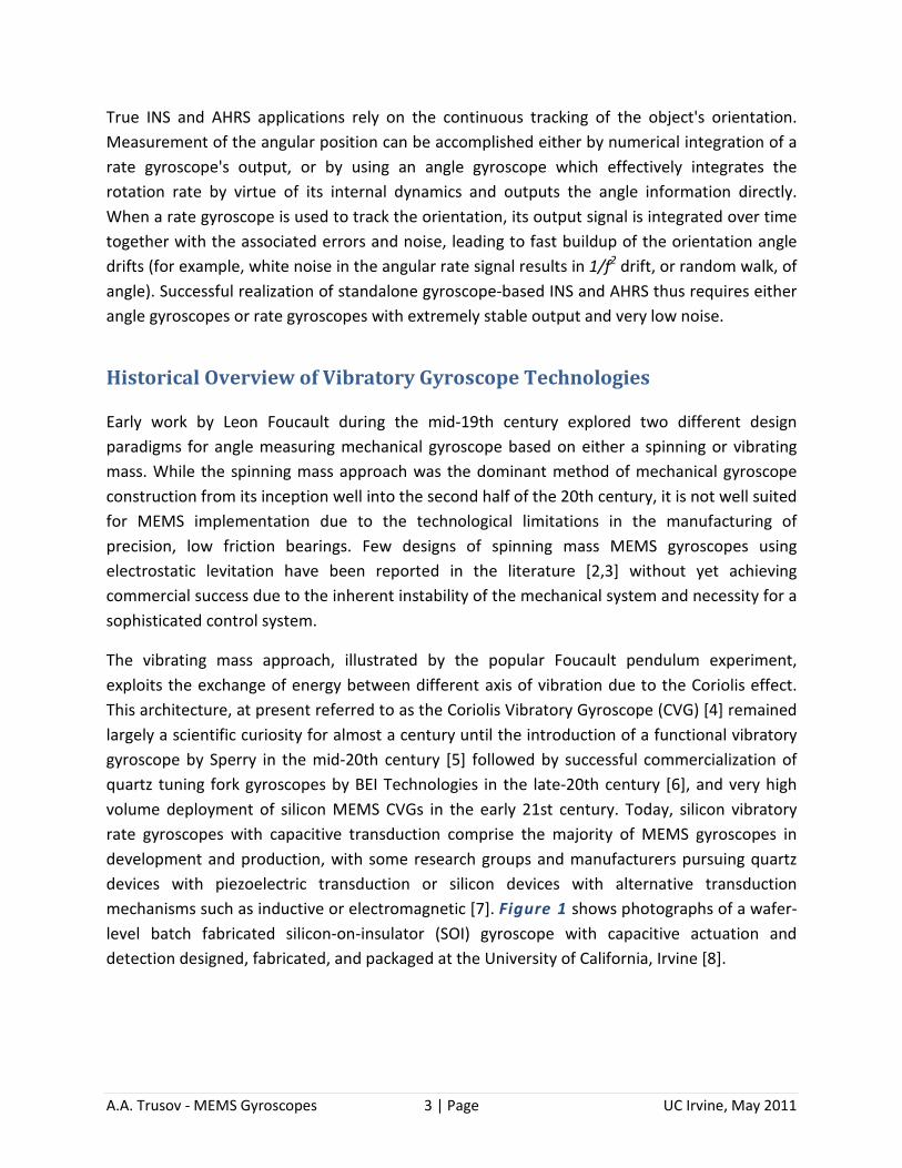
The vibrating mass approach, illustrated by the popular Foucault pendulum experiment, exploits the exchange of energy between different axis of vibration due to the Coriolis effect. This architecture, at present referred to as the Coriolis Vibratory Gyroscope (CVG) [4] remained largely a scientific curiosity for almost a century until the introduction of a functional vibratory gyroscope by Sperry in the mid-20th century [5] followed by successful commercialization of quartz tuning fork gyroscopes by BEI Technologies in the late-20th century [6], and very high volume deployment of silicon MEMS CVGs in the early 21st century. Today, silicon vibratory rate gyroscopes with capacitive transduction comprise the majority of MEMS gyroscopes in development and production, with some research groups and manufacturers pursuing quartz devices with piezoelectric transduction or silicon devices with alternative transduction mechanisms such as inductive or electromagnetic [7]. Figure 1 shows photographs of a wafer-level batch fabricated silicon-on-insulator (SOI) gyroscope with capacitive actuation and detection designed, fabricated, and packaged at the University of California, Irvine [8].
A.A. Trusov - MEMS Gyroscopes 4 | Page UC Irvine, May 2011
(a) fabricated wafer (b) gyroscope die (c) vacuum package
Figure 1: Photographs of a wafer-level fabricated silicon-on-isolator gyroscope with capacitive transduction designed, fabricated, and packaged at the University of California, Irvine.
Vibratory Gyroscope Dynamics
In this section, the principles of operation of vibratory gyroscopes are derived from the basic concepts of classical mechanics. While a planar, z-axis vibratory gyroscope is the focus of the explanation, the discussions are generic in nature and equally apply to devices with other architectures, including torsional, out-of-plane, and sensors with multiple modes of vibration for simultaneous detection of rotation in several axes. Let Sξηζ denote an inertial reference frame, in which a non-inertial frame Oxyz is moving with a linear acceleration A0=(A0x, A0y, A0z) and an angular velocity Ω=(Ωx, Ωy, Ωz) where the components of the vectors are given with respect to the moving frame. Coordinates of a point mass in the inertial and non-inertial reference frames are given by vectors ρ=(ξ, η, ζ) and r=(x, y, z) ,respectively. Newton's equation of motion of the point mass m under the action of force vector F=(Fx, Fy, Fz) with respect to the inertial reference frame Sξηζ are given by ρ''=Aabs=F/m, where the prime denotes derivative with respect to time. According to the rules of differentiation in a moving frame,
Equation 1: r'' = Arel = F/m - 2[ Ω x r' ] - ( A0 + [ Ω x [ Ω x r ]] + [ Ω' x r ].
This differential vector equation provides the strict mathematical foundation for the Coriolis vibratory gyroscopes. The Coriolis cross-product of the angular velocity Ω and the coordinate vector r=(x, y, z) governs the coupling and exchange of energy between x, y, z non-inertial axes. This effect allows measuring the input angular velocity Ω by observing the vibration pattern of the proof mass m relative to the non-inertial device reference frame Oxyz.
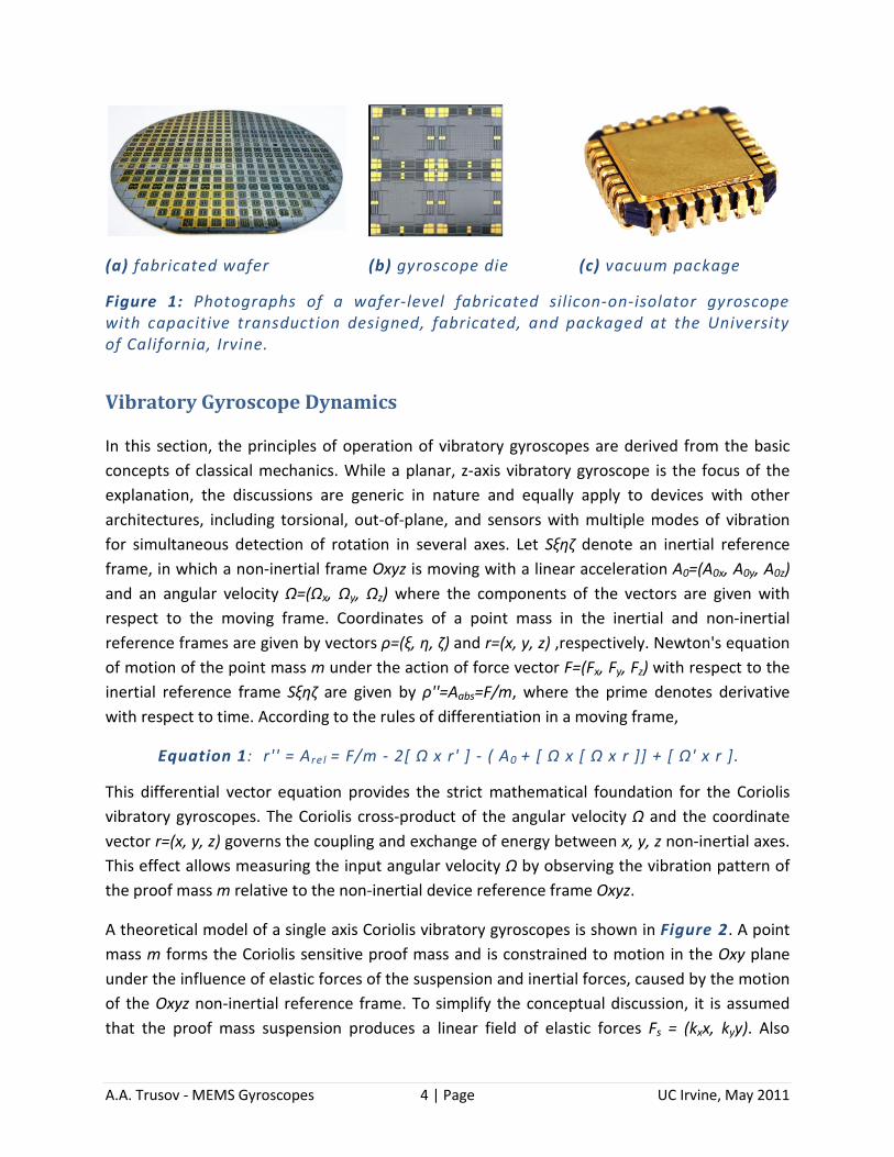
A theoretical model of a single axis Coriolis vibratory gyroscopes is shown in Figure 2. A point mass m forms the Coriolis sensitive proof mass and is constrained to motion in the Oxy plane under the influence of elastic forces of the suspension and inertial forces, caused by the motion of the Oxyz non-inertial reference frame. To simplify the conceptual discussion, it is assumed that the proof mass suspension produces a linear field of elastic forces Fs = (kxx, kyy). Also
A.A. Trusov - MEMS Gyroscopes 5 | Page UC Irvine, May 2011
neglected are the projection of the gravity field on the Oxy plane, out-of-plane Oz axis dynamics, and acceleration of the origin O. These assumptions are justified by high out-of-plane stiffness of typical bulk micromachined structures and frequency separation between the external and Coriolis accelerations. After linearization with respect to the input angular velocity vector Ω components Ωx, Ωy, Ωz, Equation 1 can be simplified to the following:
Equation 2: x'' + xωx2 - yΩz' - 2Ωzy' = Fx ,
y'' + yωy2 + xΩz' + 2Ωzx' = Fy ,
where ωx and ωx are the natural frequencies of the x- and y-mode, respectively. The following discussion will consider two different modes of operation of vibratory gyroscopes - rate measuring and angle measuring.
Figure 2: Theoretical model of a single z-axis vibratory gyroscope consisting of a proof mass m suspended in the x-y plane. The xyz non-inertial frame of reference associated with the sensor is moving relative to the inertial frame ξηζ with an angular velocity Ω=(0, 0, Ωz). Coriolis force coupling between the x and y coordinates causes energy exchange which is used to detect the input rate Ωz.
Rate Gyroscope Operation
Rate gyroscopes are operated with inherent non-symmetry between the Ox axis, designated as the drive-mode, and the Oy axis, designated as the sense-mode. The drive-mode is operated in the forced vibrations mode, where the excitation force Fx is a sinusoidal waveform with amplitude f and angular frequency ωd. The sense-mode of a rate gyroscope can be operated either open-loop or in a force-to-rebalance closed loop, where a feedback force is generated to suppress the sense-mode vibrations and is simultaneously used as the measure of the input rate. Dynamics of a rate gyroscope with an open-loop sense-mode can be derived from Equation 2 as
Equation 3: x''+xωx2-yΩz'-2Ωzy'=f/m sin(ωdt),
y''+yωy2+xΩz'+2Ωzx'=0.
A.A. Trusov - MEMS Gyroscopes 6 | Page UC Irvine, May 2011
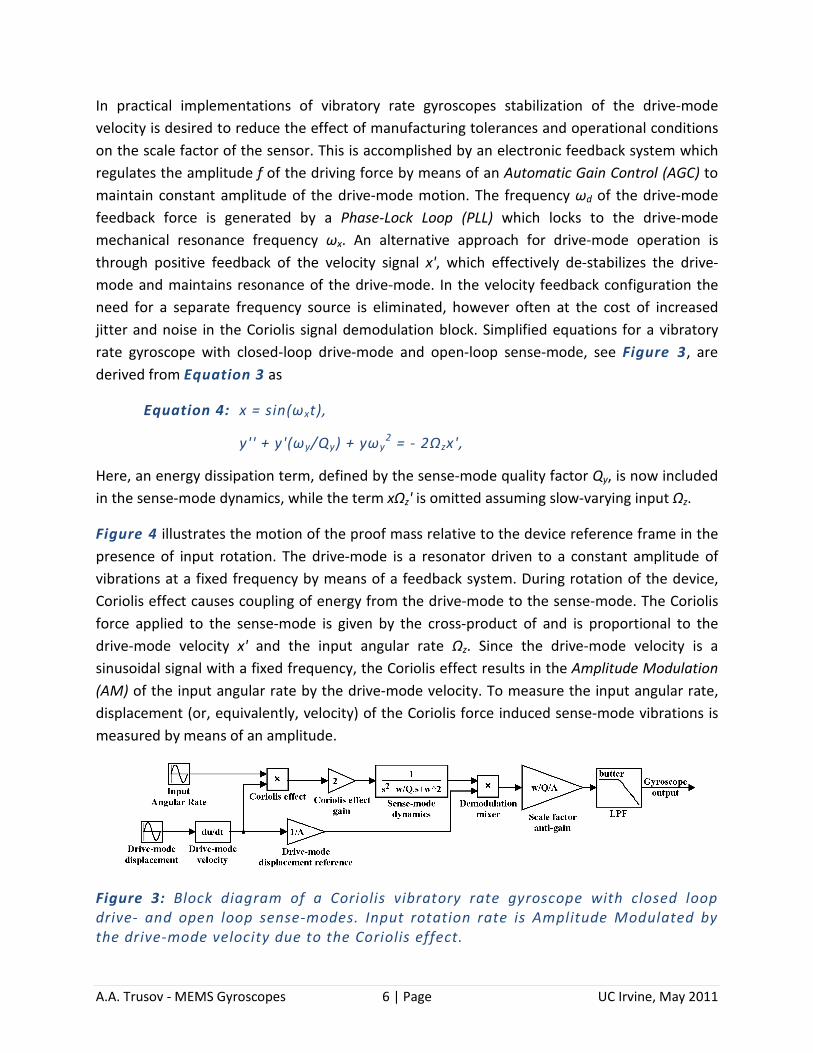
In practical implementations of vibratory rate gyroscopes stabilization of the drive-mode velocity is desired to reduce the effect of manufacturing tolerances and operational conditions on the scale factor of the sensor. This is accomplished by an electronic feedback system which regulates the amplitude f of the driving force by means of an Automatic Gain Control (AGC) to maintain constant amplitude of the drive-mode motion. The frequency ωd of the drive-mode feedback force is generated by a Phase-Lock Loop (PLL) which locks to the drive-mode mechanical resonance frequency ωx. An alternative approach for drive-mode operation is through positive feedback of the velocity signal x', which effectively de-stabilizes the drive-mode and maintains resonance of the drive-mode. In the velocity feedback configuration the need for a separate frequency source is eliminated, however often at the cost of increased jitter and noise in the Coriolis signal demodulation block. Simplified equations for a vibratory rate gyroscope with closed-loop drive-mode and open-loop sense-mode, see Figure 3, are derived from Equation 3 as
Equation 4: x = sin(ωxt),
y'' + y'(ωy/Qy) + yωy2 = - 2Ωzx',
Here, an energy dissipation term, defined by the sense-mode quality factor Qy, is now included in the sense-mode dynamics, while the term xΩz' is omitted assuming slow-varying input Ωz.
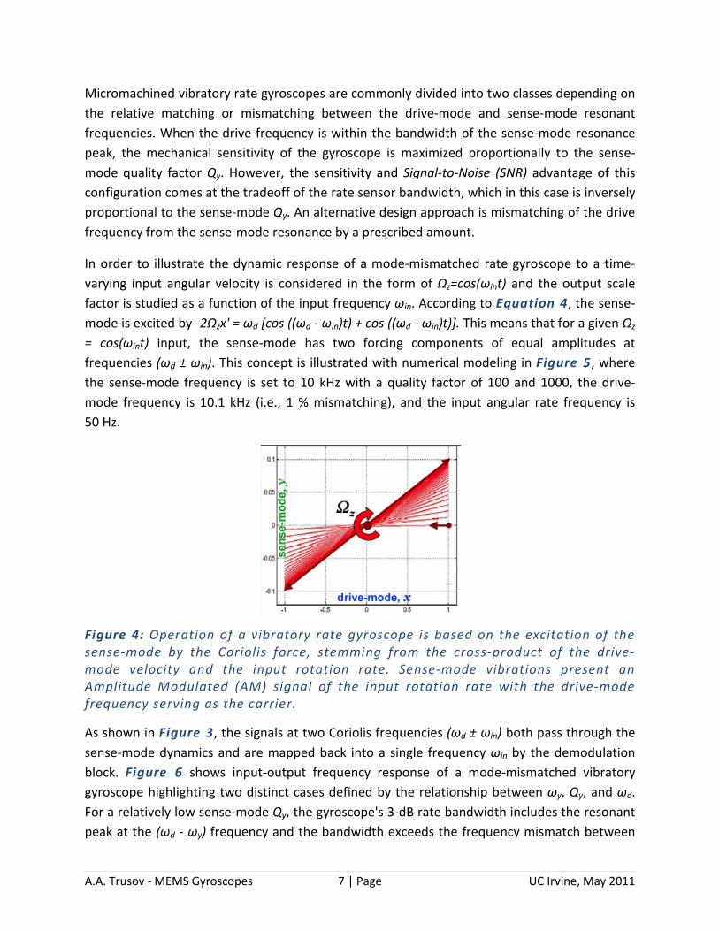
Figure 4 illustrates the motion of the proof mass relative to the device reference frame in the presence of input rotation. The drive-mode is a resonator driven to a constant amplitude of vibrations at a fixed frequency by means of a feedback system. During rotation of the device, Coriolis effect causes coupling of energy from the drive-mode to the sense-mode. The Coriolis force applied to the sense-mode is given by the cross-product of and is proportional to the drive-mode velocity x' and the input angular rate Ωz. Since the drive-mode velocity is a sinusoidal signal with a fixed frequency, the Coriolis effect results in the Amplitude Modulation (AM) of the input angular rate by the drive-mode velocity. To measure the input angular rate, displacement (or, equivalently, velocity) of the Coriolis force induced sense-mode vibrations is measured by means of an amplitude.
Figure 3: Block diagram of a Coriolis vibratory rate gyroscope with closed loop drive- and open loop sense-modes. Input rotation rate is Amplitude Modulated by the drive-mode velocity due to the Coriolis effect.
A.A. Trusov - MEMS Gyroscopes 7 | Page UC Irvine, May 2011
Micromachined vibratory rate gyroscopes are commonly divided into two classes depending on the relative matching or mismatching between the drive-mode and sense-mode resonant frequencies. When the drive frequency is within the bandwidth of the sense-mode resonance peak, the mechanical sensitivity of the gyroscope is maximized proportionally to the sense-mode quality factor Qy. However, the sensitivity and Signal-to-Noise (SNR) advantage of this configuration comes at the tradeoff of the rate sensor bandwidth, which in this case is inversely proportional to the sense-mode Qy. An alternative design approach is mismatching of the drive frequency from the sense-mode resonance by a prescribed amount.
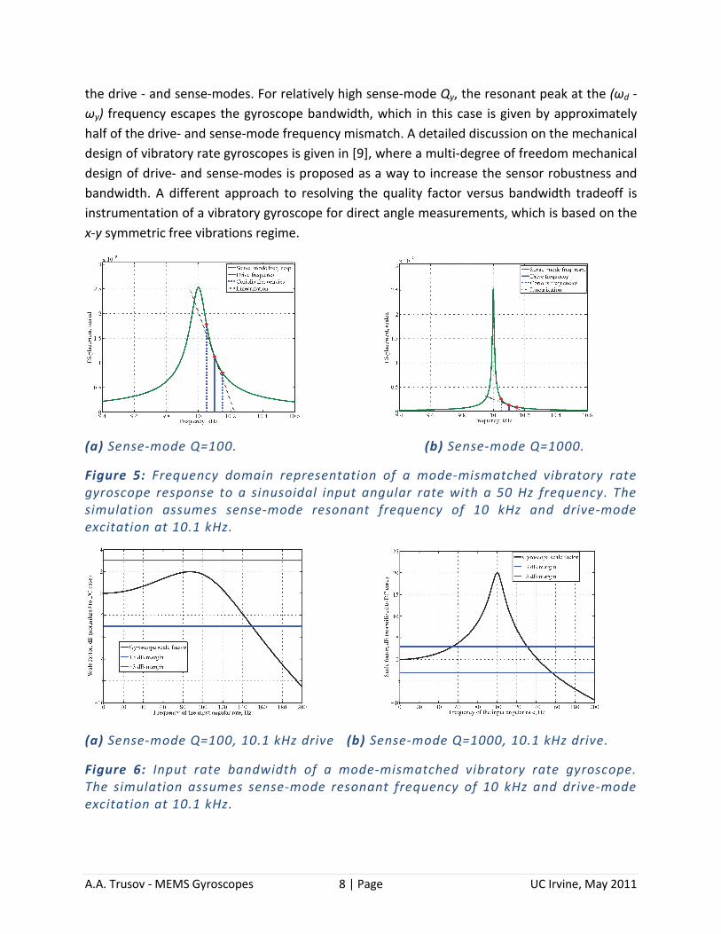
In order to illustrate the dynamic response of a mode-mismatched rate gyroscope to a time-varying input angular velocity is considered in the form of Ωz=cos(ωint) and the output scale factor is studied as a function of the input frequency ωin. According to Equation 4, the sense-mode is excited by -2Ωzx' = ωd [cos ((ωd - ωin)t) + cos ((ωd - ωin)t)]. This means that for a given Ωz = cos(ωint) input, the sense-mode has two forcing components of equal amplitudes at frequencies (ωd ± ωin). This concept is illustrated with numerical modeling in Figure 5, where the sense-mode frequency is set to 10 kHz with a quality factor of 100 and 1000, the drive-mode frequency is 10.1 kHz (i.e., 1 % mismatching), and the input angular rate frequency is 50 Hz.
Figure 4: Operation of a vibratory rate gyroscope is based on the excitation of the sense-mode by the Coriolis force, stemming from the cross-product of the drive-mode velocity and the input rotation rate. Sense-mode vibrations present an Amplitude Modulated (AM) signal of the input rotation rate with the drive-mode frequency serving as the carrier.
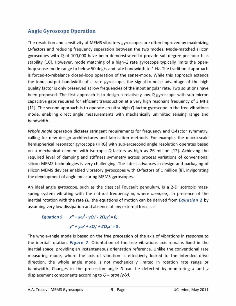
As shown in Figure 3, the signals at two Coriolis frequencies (ωd ± ωin) both pass through the sense-mode dynamics and are mapped back into a single frequency ωin by the demodulation block. Figure 6 shows input-output frequency response of a mode-mismatched vibratory gyroscope highlighting two distinct cases defined by the relationship between ωy, Qy, and ωd. For a relatively low sense-mode Qy, the gyroscope's 3-dB rate bandwidth includes the resonant peak at the (ωd - ωy) frequency and the bandwidth exceeds the frequency mismatch between
A.A. Trusov - MEMS Gyroscopes 8 | Page UC Irvine, May 2011
the drive - and sense-modes. For relatively high sense-mode Qy, the resonant peak at the (ωd - ωy) frequency escapes the gyroscope bandwidth, which in this case is given by approximately half of the drive- and sense-mode frequency mismatch. A detailed discussion on the mechanical design of vibratory rate gyroscopes is given in [9], where a multi-degree of freedom mechanical design of drive- and sense-modes is proposed as a way to increase the sensor robustness and bandwidth. A different approach to resolving the quality factor versus bandwidth tradeoff is instrumentation of a vibratory gyroscope for direct angle measurements, which is based on the x-y symmetric free vibrations regime.
(a) Sense-mode Q=100. (b) Sense-mode Q=1000.
Figure 5: Frequency domain representation of a mode-mismatched vibratory rate gyroscope response to a sinusoidal input angular rate with a 50 Hz frequency. The simulation assumes sense-mode resonant frequency of 10 kHz and drive-mode excitation at 10.1 kHz.
(a) Sense-mode Q=100, 10.1 kHz drive (b) Sense-mode Q=1000, 10.1 kHz drive.
Figure 6: Input rate bandwidth of a mode-mismatched vibratory rate gyroscope. The simulation assumes sense-mode resonant frequency of 10 kHz and drive-mode excitation at 10.1 kHz.
A.A. Trusov - MEMS Gyroscopes 9 | Page UC Irvine, May 2011
Angle Gyroscope Operation
The resolution and sensitivity of MEMS vibratory gyroscopes are often improved by maximizing Q-factors and reducing frequency separation between the two modes. Mode-matched silicon gyroscopes with Q of 100,000 have been demonstrated to provide sub-degree-per-hour bias stability [10]. However, mode matching of a high-Q rate gyroscope typically limits the open-loop sense-mode range to below 50 deg/s and rate bandwidth to 1 Hz. The traditional approach is forced-to-rebalance closed-loop operation of the sense-mode. While this approach extends the input-output bandwidth of a rate gyroscope, the signal-to-noise advantage of the high quality factor is only preserved at low frequencies of the input angular rate. Two solutions have been proposed. The first approach is to design a relatively low-Q gyroscope with sub-micron capacitive gaps required for efficient transduction at a very high resonant frequency of 3 MHz [11]. The second approach is to operate an ultra-high Q-factor gyroscope in the free vibrations mode, enabling direct angle measurements with mechanically unlimited sensing range and bandwidth.
Whole Angle operation dictates stringent requirements for frequency and Q-factor symmetry, calling for new design architectures and fabrication methods. For example, the macro-scale hemispherical resonator gyroscope (HRG) with sub-arcsecond angle resolution operates based on a mechanical element with isotropic Q-factors as high as 26 million [12]. Achieving the required level of damping and stiffness symmetry across process variations of conventional silicon MEMS technologies is very challenging. The latest advances in design and packaging of silicon MEMS devices enabled vibratory gyroscopes with Q-factors of 1 million [8], invigorating the development of angle measuring MEMS gyroscopes.
An ideal angle gyroscope, such as the classical Foucault pendulum, is a 2-D isotropic mass-spring system vibrating with the natural frequency ω, where ω=ωx=ωy. In presence of the inertial rotation with the rate Ωz, the equations of motion can be derived from Equation 2 by assuming very low dissipation and absence of any external forces as
Equation 5 x'' + xω2 - yΩz' - 2Ωzy' = 0,
y'' + yω2 + xΩz' + 2Ωzx' = 0 .
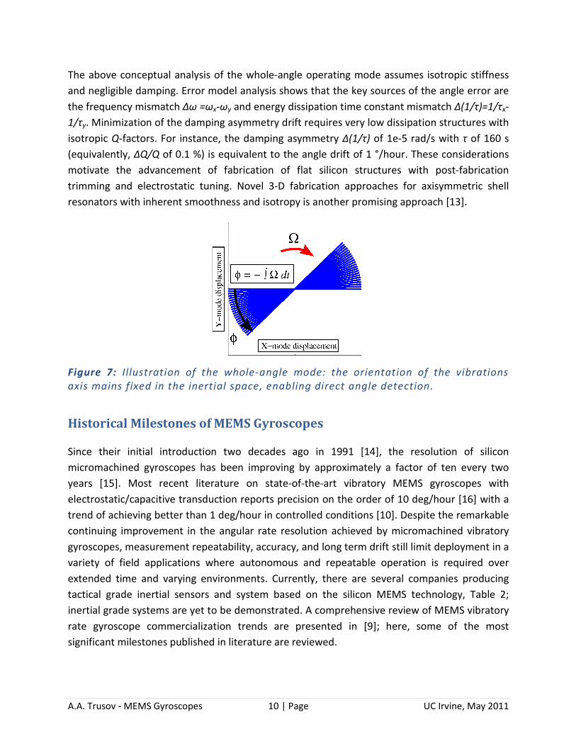
The whole-angle mode is based on the free precession of the axis of vibrations in response to the inertial rotation, Figure 7. Orientation of the free vibrations axis remains fixed in the inertial space, providing an instantaneous orientation reference. Unlike the conventional rate measuring mode, where the axis of vibration is effectively locked to the intended drive direction, the whole angle mode is not mechanically limited in rotation rate range or bandwidth. Changes in the precession angle Θ can be detected by monitoring x and y displacement components according to Θ = atan (y/x).
A.A. Trusov - MEMS Gyroscopes 10 | Page UC Irvine, May 2011
The above conceptual analysis of the whole-angle operating mode assumes isotropic stiffness and negligible damping. Error model analysis shows that the key sources of the angle error are the frequency mismatch Δω =ωx-ωy and energy dissipation time constant mismatch Δ(1/τ)=1/τx-1/τy. Minimization of the damping asymmetry drift requires very low dissipation structures with isotropic Q-factors. For instance, the damping asymmetry Δ(1/τ) of 1e-5 rad/s with τ of 160 s (equivalently, ΔQ/Q of 0.1 %) is equivalent to the angle drift of 1 °/hour. These considerations motivate the advancement of fabrication of flat silicon structures with post-fabrication trimming and electrostatic tuning. Novel 3-D fabrication approaches for axisymmetric shell resonators with inherent smoothness and isotropy is another promising approach [13].
Figure 7: Illustration of the whole-angle mode: the orientation of the vibrations axis mains fixed in the inertial space, enabling direct angle detection.
Historical Milestones of MEMS Gyroscopes
Since their initial introduction two decades ago in 1991 [14], the resolution of silicon micromachined gyroscopes has been improving by approximately a factor of ten every two years [15]. Most recent literature on state-of-the-art vibratory MEMS gyroscopes with electrostatic/capacitive transduction reports precision on the order of 10 deg/hour [16] with a trend of achieving better than 1 deg/hour in controlled conditions [10]. Despite the remarkable continuing improvement in the angular rate resolution achieved by micromachined vibratory gyroscopes, measurement repeatability, accuracy, and long term drift still limit deployment in a variety of field applications where autonomous and repeatable operation is required over extended time and varying environments. Currently, there are several companies producing tactical grade inertial sensors and system based on the silicon MEMS technology, Table 2; inertial grade systems are yet to be demonstrated. A comprehensive review of MEMS vibratory rate gyroscope commercialization trends are presented in [9]; here, some of the most significant milestones published in literature are reviewed.
A.A. Trusov - MEMS Gyroscopes 11 | Page UC Irvine, May 2011
In 2002, Analog Devices reported a surface micromachined polysilicon gyroscope with a 50 deg/hour random bias instability achieved at the averaging time below 1 minute [17]. The single-chip integrated device was not vacuum packaged, which in combination with a 4 micrometer thin structural layer translates into a relatively low sense-mode quality factor on the order of 20. This family of gyroscopes has since gained a widespread acceptance and popularity in consumer and automotive markets, with new gyroscopes introduced every few years. According to Table 2 , this device falls into the middle of the Rate grade category, as defined in [15]. Publication [17] also projected that the random bias can be improved by approximately 80 % by introducing new electronics design, suggesting a mechanical-thermal noise floor on the level of 10 deg/hour. The newer generation design of the gyroscope has four electrically coupled, low quality factor surface micromachined polysilicon Coriolis vibratory gyroscopes integrated on the same die together with the electronics in order to suppress the effect of external vibrations; improvement of the bias instability was also reported.
A higher performance polysilicon micromachined gyroscope from Bosch was reported in 2007 in [18]. The device has 1 deg/hour random bias instability, showing its potential for the Tactical grade performance category, Table 2. However, this high sensitivity occurs only at extremely long, often impractical, averaging times on the order 160 minutes. The minimal detectable signal at practical bandwidths was lower (30 deg/hour for a 10 Hz bandwidth, and 100 deg/hour for a 100 Hz bandwidth). This device was not integrated with electronics on the die level (hybrid integration of the MEMS and the electronics dies was done on a package level), and its low noise levels are associated with vacuum packaging and high sense-mode quality factor.
A 2006 publication [16] from Charles Stark Draper Laboratory provides an insightful review of performance characteristics of a few additional commercial MEMS gyroscopes. According to this paper, the uncompensated thermal sensitivities of higher performance quartz tuning fork gyroscopes from Custom Sensors and Technologies (formerly Systron Donner/BEI) was reported at 300 ppm/deg C achieved primarily due to extremely low sensitivity of the material's properties to temperature. Analog Devices' automotive grade angular rate sensor ADXRS150 scale factor uncompensated thermal sensitivity was quoted as 1700 ppm/deg C. Honeywell's dissolved wafer, single crystal silicon on glass, device based on the Draper laboratory design achieves a 250 ppm/deg C scale factor temperature coefficient.
Surveying the literature confirms that in recent years performance of the commercial MEMS gyroscopes continued to improve, reaching the criteria of Tactical grade category; however, performance of these gyroscopes is still two to three orders of magnitude away from the Inertial grade. The reported progress often comes with costly refinements of the fabrication and vacuum packaging processes. Most reported commercial gyroscopes have intricate electronic compensation for such parameters as temperature drift and aging. From the
A.A. Trusov - MEMS Gyroscopes 12 | Page UC Irvine, May 2011
mechanical structure point of view, the majority of commercial gyroscopes consist of several coupled, anti-phase driven vibratory gyroscope elements (2- or 4-tine tuning fork architecture) to suppress external vibrations.
Striking breakthroughs in very large scale commercialization of very low cost (<$1 per axis) MEMS rate gyroscopes and accelerometers have been achieved during 2005-2010 by InvenSense, ST Microelectornics, and other suppliers targeting consumer electronics devices. In contrast to the automotive or defense applications with stringent requirements for reliability and high accuracy, size and price are the main drivers for the consumer electronics applications. Current emphasis in low-cost inertial sensor commercialization is on a single package and ultimately single chip integration of 6 axis of inertial sensing, augmented with a 3 axis magnetometer and a pressure sensor. Kalman filter based sensor fusion is employed to produce useful 6-axis position and orientation information by taking advantage of the inherent sensory redundancy in the 10 degrees of freedom produced by these sensors.
Systematic Performance Parameters
In this section an explanation is provided of several most important terms used to describe and quantify the characteristics of Coriolis vibratory gyroscopes [4] with emphasis on deterministic and stochastic aspects of performance or rate sensors.
Scale factor (SF) is the ratio between the output and input signals in the linear regime of measurements. For rate gyroscopes with analog voltage output, SF is often expressed in V/(deg/s) or V/(deg/hour). Several non-ideal properties of SF are typically characterized, including sensitivity to temperature (in ppm/deg C) and linear accelerations (in ppm/g), SF turn-on repeatability (in ppm for 1-σ or 3-σ statistics). Common sources of SF error in MEMS gyroscopes are fabrication imperfections, drifts of drive- and sense-mode resonant frequencies and quality factors, and drifts of electronics gains, especially due to turn-on self-heating.
Bandwidth (BW) is the range of the input signal's frequencies which can be measured well by the gyroscope. BW is often specified assuming a ±3 dB margin around the gain (Scale Factor) of the gyroscope for a non-zero constant input rate. In general, the gyroscope's input-output BW should be distinguished from the individual mechanical bandwidths of the drive- or the sense-modes of vibration. A more complete picture of the gyroscopes dynamic response is given by a frequency response plot.
Bias is the apparent output of the rotation sensor for zero input rate assuming specific fixed operational conditions (e.g. temperature). For rate gyroscopes Bias is expressed in deg/s or deg/hour units. Typical associated non-idealities are the sensitivity of bias to temperature (in
A.A. Trusov - MEMS Gyroscopes 13 | Page UC Irvine, May 2011
deg/s/deg C or deg/hour/deg C) and acceleration (deg/s/g or deg/hour/g), Bias turn-on repeatability (in deg/s or deg/hour for 1-σ or 3-σ statistics). A major sources of Bias error in MEMS gyroscopes is mechanical quadrature - the undesired sense-mode vibration caused by the fabrication imperfections. While phase-sensitive demodulation suppresses the quadrature signal by several orders of magnitude, minute phase drifts in the system cause so called quadrature spillover error -- the erroneous change of bias due to the partially unsuppressed quadrature. Even though random noise and drift effects are often referred to as bias, it is important to draw a clear distinction between systematic and random changes of output.
Tables
Table 1: Typical performance parameters of state-of-the-art commercial MEMS rate gyroscopes [16].
Parameter Value Rate resolution 5-10 deg/hour/√Hz Temperature sensitivity of bias 10 deg/hour/deg C Bias repeatability (temperature, turn on) 30 deg/hour Temperature sensitivity of scale factor 250 ppm/deg C Scale factor repeatability (temperature, turn on) 400 ppm
Table 2: Performance requirements for three grades of gyroscopes [15].
Parameter, unit Rate grade Tactical grade
Inertial grade
Angle random walk (ARW), deg/√hour >0.5 0.5-0.05 <0.001 ARW-equivalent rate resolution, deg/hour/√Hz
>30 30-3 <0.06
Bias drift, deg/hour 10-1000 0.1-10 <0.01 Scale factor accuracy, ppm 100-1000 10-100 <1 Full scale linear range, deg/s 50-1000 >500 >400 Bandwidth, Hz >70 100 100
References
[1] Shkel, A.M.; , "Type I and Type II Micromachined Vibratory Gyroscopes," Position, Location, And Navigation Symposium, 2006 IEEE/ION , vol., no., pp. 586- 593, April 25-27, 2006 doi: 10.1109/PLANS.2006.1650648 URL: http://ieeexplore.ieee.org/stamp/stamp.jsp?tp=&arnumber=1650648&isnumber=34615
A.A. Trusov - MEMS Gyroscopes 14 | Page UC Irvine, May 2011
[2] Nakamura, S.; , "MEMS inertial sensor toward higher accuracy & multi-axis sensing," Sensors, 2005 IEEE , vol., no., pp.4 pp., Oct. 30 2005-Nov. 3 2005 doi: 10.1109/ICSENS.2005.1597855 URL: http://ieeexplore.ieee.org/stamp/stamp.jsp?tp=&arnumber=1597855&isnumber=33608
[3] Damrongsak, B.; Kraft, M.; , "A micromachined electrostatically suspended gyroscope with digital force feedback," Sensors, 2005 IEEE , vol., no., pp.4 pp., Oct. 30 2005-Nov. 3 200 doi: 10.1109/ICSENS.2005.1597720 URL: http://ieeexplore.ieee.org/stamp/stamp.jsp?tp=&arnumber=1597720&isnumber=33608
[4] "IEEE Standard Specification Format Guide and Test Procedure for Coriolis Vibratory Gyros," IEEE Std 1431-2004 , vol., no., pp.0_1-69, 2004 doi: 10.1109/IEEESTD.2004.95744 URL: http://ieeexplore.ieee.org/stamp/stamp.jsp?tp=&arnumber=1394849&isnumber=30352
[5] Barnaby, R.E.; Chatterton, J.B.; Gerring, F.H., " General theory and operational characteristics of Gyrotron angular rate tachometer," Aeronautical Engineering Review, Vol. 12, Issue 11, p.31-36 Nov 1953
[6] Madni, A.M.; Costlow, L.E.; Knowles, S.J.; , "Common design techniques for BEI GyroChip quartz rate sensors for both automotive and aerospace/defense markets," Sensors Journal, IEEE , vol.3, no.5, pp. 569- 578, Oct. 2003 doi: 10.1109/JSEN.2003.817728 URL: http://ieeexplore.ieee.org/stamp/stamp.jsp?tp=&arnumber=1234893&isnumber=27682
[7] Acar, C.; Schofield, A.R.; Trusov, A.A.; Costlow, L.E.; Shkel, A.M.; , "Environmentally Robust MEMS Vibratory Gyroscopes for Automotive Applications," Sensors Journal, IEEE , vol.9, no.12, pp.1895-1906, Dec. 2009 doi: 10.1109/JSEN.2009.2026466 URL: http://ieeexplore.ieee.org/stamp/stamp.jsp?tp=&arnumber=5297817&isnumber=5290388
[8] Trusov, Alexander A.; Prikhodko, Igor P.; Zotov, Sergei A.; Schofield, Adam R.; Shkel, Andrei M.; , "Ultra-high Q silicon gyroscopes with interchangeable rate and whole angle modes of operation," Sensors, 2010 IEEE , vol., no., pp.864-867, 1-4 Nov. 2010 doi: 10.1109/ICSENS.2010.5690867 URL: http://ieeexplore.ieee.org/stamp/stamp.jsp?tp=&arnumber=5690867&isnumber=5689839
[9] Cenk Acar, Andrei M. Shkel, "MEMS vibratory gyroscopes: structural approaches to improve robustness," Springer, 2009, ISBN 0387095357, 9780387095356
[10] Zaman, M.F.; Sharma, A.; Zhili Hao; Ayazi, F.; , "A Mode-Matched Silicon-Yaw Tuning-Fork Gyroscope With Subdegree-Per-Hour Allan Deviation Bias Instability," Microelectromechanical Systems, Journal of , vol.17, no.6, pp.1526-1536, Dec. 2008
A.A. Trusov - MEMS Gyroscopes 15 | Page UC Irvine, May 2011
doi: 10.1109/JMEMS.2008.2004794 URL: http://ieeexplore.ieee.org/stamp/stamp.jsp?tp=&arnumber=4636724&isnumber=4681904
[11] Wang-kyung Sung; Dalal, M.; Ayazi, F.; , "A 3MHz spoke gyroscope with wide bandwidth and large dynamic range," Micro Electro Mechanical Systems (MEMS), 2010 IEEE 23rd International Conference on , vol., no., pp.104-107, 24-28 Jan. 2010 doi: 10.1109/MEMSYS.2010.5442554 URL: http://ieeexplore.ieee.org/stamp/stamp.jsp?tp=&arnumber=5442554&isnumber=5442276
[12] Rozelle, D., "The Hemispherical Resonator Gyro: From Wineglass to the Planets," Proc. 19th AAS/AIAA Space Flight Mechanics Meeting, pp. 1157-1178, 2009
[13] Sergei A. Zotov, Igor P.Prikhodko, Alexander A. Trusov, Andrei M. Shkel, "3-D Micromachined Spherical Shell Resonators with Integrated Electromagnetic and Electrostatic Transducers," Solid-State Sensors, Actuators, and Microsystems Workshop 2010, Hilton Head Island, South Carolina, USA, June 6-10, 2010.
[14] Greiff, P.; Boxenhorn, B.; King, T.; Niles, L.; , "Silicon monolithic micromechanical gyroscope," Solid-State Sensors and Actuators, 1991. Digest of Technical Papers, TRANSDUCERS '91., 1991 International Conference on , vol., no., pp.966-968, 24-27 Jun 1991 doi: 10.1109/SENSOR.1991.149051 URL: http://ieeexplore.ieee.org/stamp/stamp.jsp?tp=&arnumber=149051&isnumber=3940
[15] Yazdi, N.; Ayazi, F.; Najafi, K.; , "Micromachined inertial sensors," Proceedings of the IEEE , vol.86, no.8, pp.1640-1659, Aug 1998 doi: 10.1109/5.704269 URL: http://ieeexplore.ieee.org/stamp/stamp.jsp?tp=&arnumber=704269&isnumber=15216
[16] Weinberg, M.S.; Kourepenis, A.; , "Error sources in in-plane silicon tuning-fork MEMS gyroscopes," Microelectromechanical Systems, Journal of , vol.15, no.3, pp. 479- 491, June 2006 doi: 10.1109/JMEMS.2006.876779 URL: http://ieeexplore.ieee.org/stamp/stamp.jsp?tp=&arnumber=1638473&isnumber=34353
[17] Geen, J.A.; Sherman, S.J.; Chang, J.F.; Lewis, S.R.; , "Single-chip surface micromachined integrated gyroscope with 50°/h Allan deviation," Solid-State Circuits, IEEE Journal of , vol.37, no.12, pp. 1860- 1866, Dec 2002 doi: 10.1109/JSSC.2002.804345 URL: http://ieeexplore.ieee.org/stamp/stamp.jsp?tp=&arnumber=1088117&isnumber=23646
[18] Neul, R.; Gomez, U.-M.; Kehr, K.; Bauer, W.; Classen, J.; Doring, C.; Esch, E.; Gotz, S.; Hauer, J.; Kuhlmann, B.; Lang, C.; Veith, M.; Willig, R.; , "Micromachined Angular Rate Sensors for Automotive Applications," Sensors Journal, IEEE , vol.7, no.2, pp.302-309, Feb. 2007 doi: 10.1109/JSEN.2006.888610 URL: http://ieeexplore.ieee.org/stamp/stamp.jsp?tp=&arnumber=4066977&isnumber=4049782

![New Adaptive Mode of Operation for MEMS Gyroscopes · The design and fabrication of MEMS gyroscopeshas been the subject of extensive ... performance [1,3]. Geometrical imperfections](https://img.pdfslide.us/doc/110x75/5e8792413f321a69d3794297/new-adaptive-mode-of-operation-for-mems-gyroscopes-the-design-and-fabrication-of.jpg)


![An overview of Optical Gyroscopes Theory, Practical ... Gyroscopes[1].pdf · An overview of Optical Gyroscopes Theory, Practical Aspects, Applications and Future Trends By Adi Shamir](https://img.pdfslide.us/doc/110x75/5adedc2a7f8b9ad66b8c1829/an-overview-of-optical-gyroscopes-theory-practical-gyroscopes1pdfan-overview.jpg)