Embed Size (px)
Citation preview
October 30 - November 1, 2007 FAP Annual Meeting - Hypersonics Project 1
Overview of an Advanced Hypersonic Structural Concept Test Program
Craig A. Stephens, Larry D. Hudson, and Anthony PiazzaNASA Dryden Flight Research Center
October 30 - November 1, 2007 FAP Annual Meeting - Hypersonics Project 2
Outline
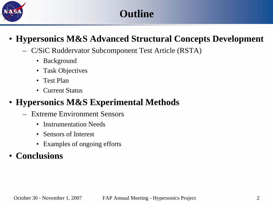
• Hypersonics M&S Advanced Structural Concepts Development– C/SiC Ruddervator Subcomponent Test Article (RSTA)
• Background• Task Objectives• Test Plan• Current Status
• Hypersonics M&S Experimental Methods– Extreme Environment Sensors
• Instrumentation Needs• Sensors of Interest• Examples of ongoing efforts
• Conclusions
October 30 - November 1, 2007 FAP Annual Meeting - Hypersonics Project 3
C/SiC Ruddervator Subcomponent Test ArticleBackground
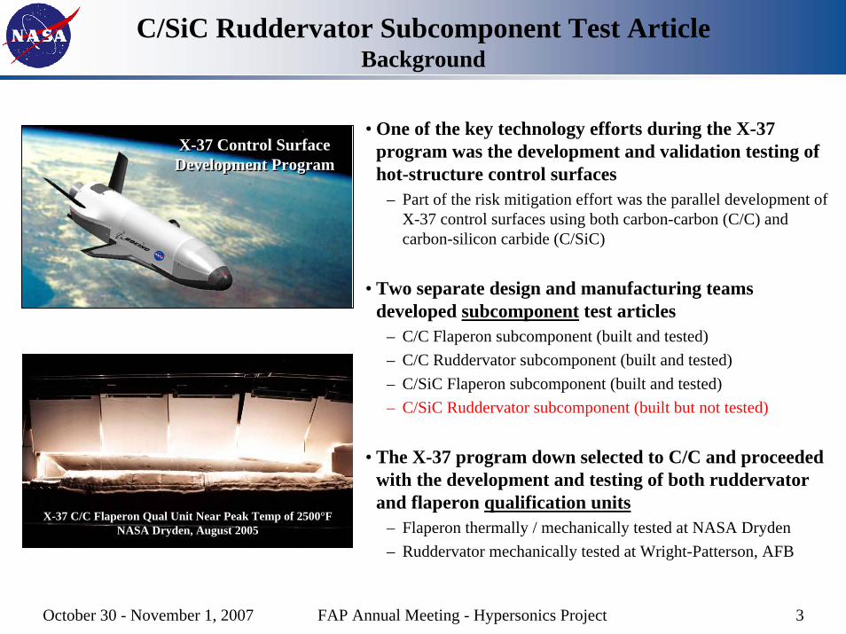
• One of the key technology efforts during the X-37 program was the development and validation testing of hot-structure control surfaces
– Part of the risk mitigation effort was the parallel development of X-37 control surfaces using both carbon-carbon (C/C) and carbon-silicon carbide (C/SiC)
• Two separate design and manufacturing teams developed subcomponent test articles
– C/C Flaperon subcomponent (built and tested)– C/C Ruddervator subcomponent (built and tested)– C/SiC Flaperon subcomponent (built and tested)– C/SiC Ruddervator subcomponent (built but not tested)
• The X-37 program down selected to C/C and proceeded with the development and testing of both ruddervator and flaperon qualification units
– Flaperon thermally / mechanically tested at NASA Dryden– Ruddervator mechanically tested at Wright-Patterson, AFB
X-37 C/C Flaperon Qual Unit Near Peak Temp of 2500°FNASA Dryden, August 2005
X-37 Control Surface Development ProgramX-37 Control Surface
Development Program
October 30 - November 1, 2007 FAP Annual Meeting - Hypersonics Project 4
C/SiC Ruddervator Subcomponent Test ArticleBackground (Continued)
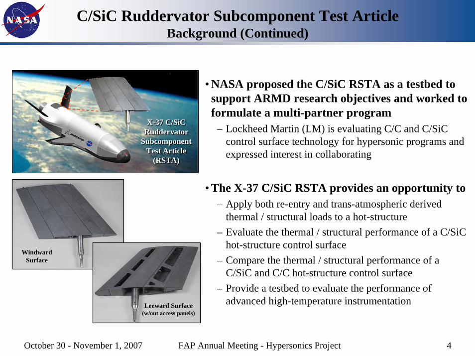
• NASA proposed the C/SiC RSTA as a testbed to support ARMD research objectives and worked to formulate a multi-partner program
– Lockheed Martin (LM) is evaluating C/C and C/SiC control surface technology for hypersonic programs and expressed interest in collaborating
• The X-37 C/SiC RSTA provides an opportunity to– Apply both re-entry and trans-atmospheric derived
thermal / structural loads to a hot-structure – Evaluate the thermal / structural performance of a C/SiC
hot-structure control surface– Compare the thermal / structural performance of a
C/SiC and C/C hot-structure control surface– Provide a testbed to evaluate the performance of
advanced high-temperature instrumentation
X-37 C/SiC Ruddervator
Subcomponent Test Article
(RSTA)
X-37 C/SiC Ruddervator
Subcomponent Test Article
(RSTA)
Windward Surface
Leeward Surface(w/out access panels)
October 30 - November 1, 2007 FAP Annual Meeting - Hypersonics Project 5
C/SiC Ruddervator Subcomponent Test ArticleTeam Roles and Responsibilities
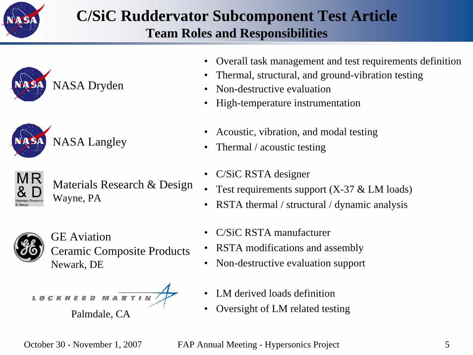
• Overall task management and test requirements definition• Thermal, structural, and ground-vibration testing• Non-destructive evaluation• High-temperature instrumentation
NASA Dryden
• Acoustic, vibration, and modal testing• Thermal / acoustic testingNASA Langley
• C/SiC RSTA designer• Test requirements support (X-37 & LM loads)• RSTA thermal / structural / dynamic analysis
Materials Research & DesignWayne, PA
• C/SiC RSTA manufacturer• RSTA modifications and assembly• Non-destructive evaluation support
GE AviationCeramic Composite ProductsNewark, DE
• LM derived loads definition• Oversight of LM related testingPalmdale, CA
October 30 - November 1, 2007 FAP Annual Meeting - Hypersonics Project 6
C/SiC Ruddervator Subcomponent Test ArticleTest Objectives
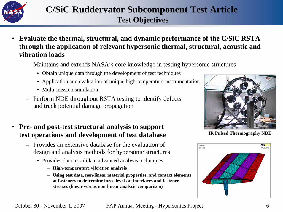
• Evaluate the thermal, structural, and dynamic performance of the C/SiC RSTA through the application of relevant hypersonic thermal, structural, acoustic and vibration loads
– Maintains and extends NASA’s core knowledge in testing hypersonic structures• Obtain unique data through the development of test techniques• Application and evaluation of unique high-temperature instrumentation• Multi-mission simulation
– Perform NDE throughout RSTA testing to identify defects and track potential damage propagation
• Pre- and post-test structural analysis to support test operations and development of test database
– Provides an extensive database for the evaluation of design and analysis methods for hypersonic structures
• Provides data to validate advanced analysis techniques– High-temperature vibration analysis– Using test data, non-linear material properties, and contact elements
at fasteners to determine force levels at interfaces and fastener stresses (linear versus non-linear analysis comparison)
IR Pulsed Thermography NDE
October 30 - November 1, 2007 FAP Annual Meeting - Hypersonics Project 7
C/SiC Ruddervator Subcomponent Test ArticleTest Plan
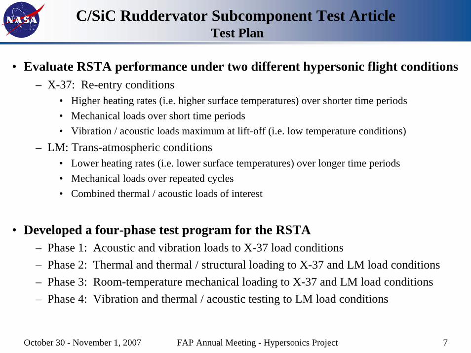
• Evaluate RSTA performance under two different hypersonic flight conditions– X-37: Re-entry conditions
• Higher heating rates (i.e. higher surface temperatures) over shorter time periods• Mechanical loads over short time periods• Vibration / acoustic loads maximum at lift-off (i.e. low temperature conditions)
– LM: Trans-atmospheric conditions• Lower heating rates (i.e. lower surface temperatures) over longer time periods• Mechanical loads over repeated cycles• Combined thermal / acoustic loads of interest
• Developed a four-phase test program for the RSTA– Phase 1: Acoustic and vibration loads to X-37 load conditions– Phase 2: Thermal and thermal / structural loading to X-37 and LM load conditions– Phase 3: Room-temperature mechanical loading to X-37 and LM load conditions– Phase 4: Vibration and thermal / acoustic testing to LM load conditions
October 30 - November 1, 2007 FAP Annual Meeting - Hypersonics Project 8
C/SiC Ruddervator Subcomponent Test ArticlePhase 1 Tests (NASA Langley, Completed)
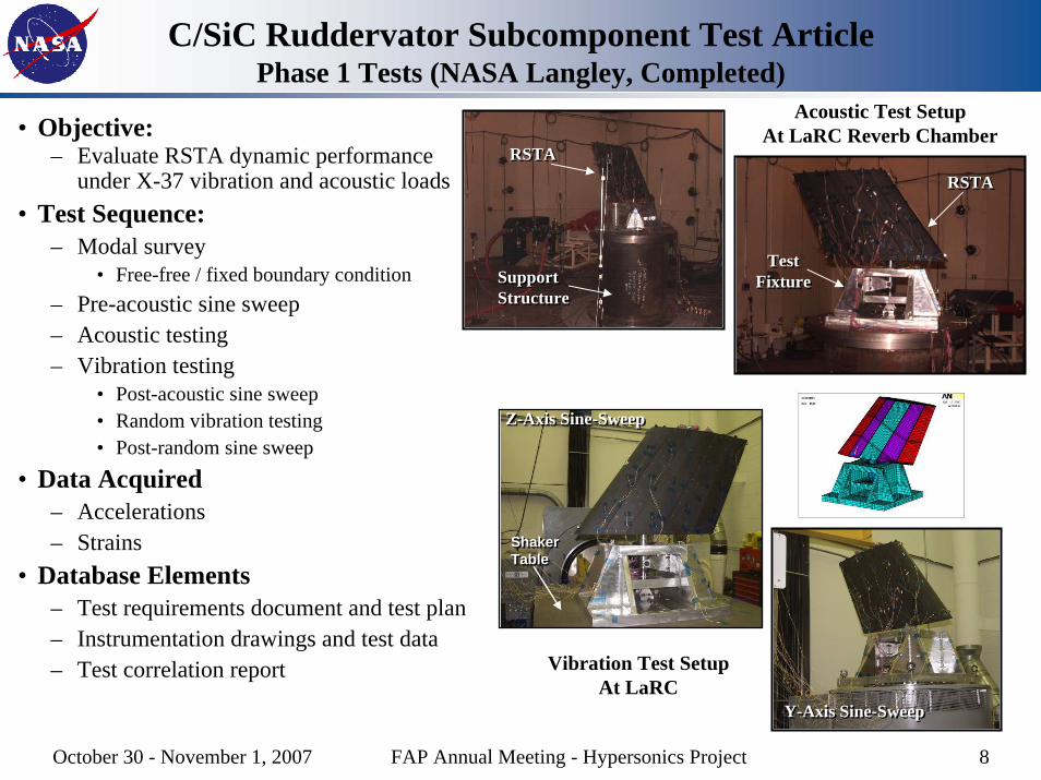
• Objective:– Evaluate RSTA dynamic performance
under X-37 vibration and acoustic loads• Test Sequence:
– Modal survey • Free-free / fixed boundary condition
– Pre-acoustic sine sweep– Acoustic testing– Vibration testing
• Post-acoustic sine sweep• Random vibration testing• Post-random sine sweep
• Data Acquired– Accelerations– Strains
• Database Elements– Test requirements document and test plan– Instrumentation drawings and test data– Test correlation report
Acoustic Test SetupAt LaRC Reverb Chamber
RSTARSTA
SupportStructureSupportStructure
RSTARSTA
Test Fixture
Test Fixture
Z-Axis Sine-Sweep Z-Axis Sine-Sweep
Shaker TableShaker Table
Y-Axis Sine-Sweep Y-Axis Sine-Sweep
Vibration Test SetupAt LaRC
October 30 - November 1, 2007 FAP Annual Meeting - Hypersonics Project 9
C/SiC Ruddervator Subcomponent Test ArticlePhase 2 Tests (NASA Dryden, In Progress)
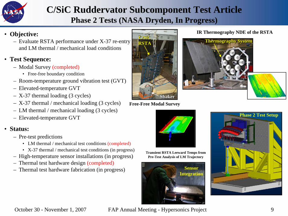
• Objective:– Evaluate RSTA performance under X-37 re-entry
and LM thermal / mechanical load conditions
• Test Sequence:– Modal Survey (completed)
• Free-free boundary condition– Room-temperature ground vibration test (GVT)– Elevated-temperature GVT– X-37 thermal loading (3 cycles)– X-37 thermal / mechanical loading (3 cycles)– LM thermal / mechanical loading (3 cycles)– Elevated-temperature GVT
• Status:– Pre-test predictions
• LM thermal / mechanical test conditions (completed)• X-37 thermal / mechanical test conditions (in progress)
– High-temperature sensor installations (in progress)– Thermal test hardware design (completed)– Thermal test hardware fabrication (in progress)
C/SiC RSTAC/SiC RSTA
ShakerShaker
IR Thermography NDE of the RSTA
Thermography SystemThermography System
Free-Free Modal Survey
Transient RSTA Leeward Temps from Pre-Test Analysis of LM Trajectory
Phase 2 Test Setup
Sensor Integration
October 30 - November 1, 2007 FAP Annual Meeting - Hypersonics Project 10
C/SiC Ruddervator Subcomponent Test Article Phase 3 & 4 Tests
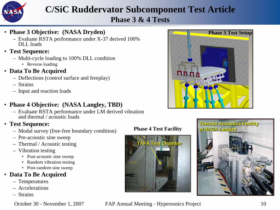
• Phase 3 Objective: (NASA Dryden)– Evaluate RSTA performance under X-37 derived 100%
DLL loads• Test Sequence:
– Multi-cycle loading to 100% DLL condition• Reverse loading
• Data To Be Acquired– Deflections (control surface and freeplay)– Strains– Input and reaction loads
• Phase 4 Objective: (NASA Langley, TBD)– Evaluate RSTA performance under LM derived vibration
and thermal / acoustic loads• Test Sequence:
– Modal survey (free-free boundary condition)– Pre-acoustic sine sweep– Thermal / Acoustic testing– Vibration testing
• Post-acoustic sine sweep• Random vibration testing• Post-random sine sweep
• Data To Be Acquired– Temperatures– Accelerations– Strains
Phase 3 Test Setup
Thermal Acoustics Facilityat NASA LangleyThermal Acoustics Facilityat NASA Langley
TAFA Test ChamberTAFA Test Chamber
Phase 4 Test Facility
October 30 - November 1, 2007 FAP Annual Meeting - Hypersonics Project 11
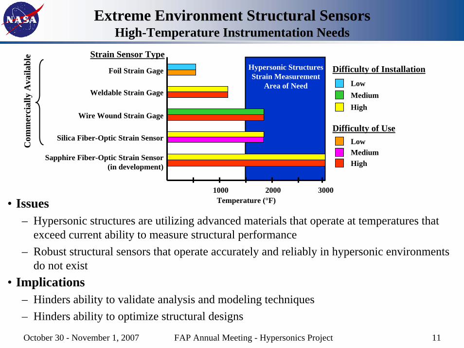
Extreme Environment Structural SensorsHigh-Temperature Instrumentation Needs
Foil Strain Gage
Weldable Strain Gage
Wire Wound Strain Gage
Silica Fiber-Optic Strain Sensor
2000
Sapphire Fiber-Optic Strain Sensor(in development)
30001000
Hypersonic StructuresStrain Measurement
Area of Need
Com
mer
cial
ly A
vaila
ble Strain Sensor Type
Difficulty of InstallationLowMediumHigh
Difficulty of UseLowMediumHigh
• Issues– Hypersonic structures are utilizing advanced materials that operate at temperatures that
exceed current ability to measure structural performance – Robust structural sensors that operate accurately and reliably in hypersonic environments
do not exist• Implications
– Hinders ability to validate analysis and modeling techniques– Hinders ability to optimize structural designs
Temperature (°F)

October 30 - November 1, 2007 FAP Annual Meeting - Hypersonics Project 12
Extreme Environment Structural SensorsInstrumentation Attachment Needs
• Hypersonic structural test or flight articles are usually one-of-a-kind, expensive, and time consuming to manufacture
– Metallics– Metal matrix composites– Superalloys – High-temperature composites (i.e. C/C, C/SiC, SiC/SiC)
• Issues– Integrating structural sensors that do not compromise
structural integrity • Drilling holes, mechanical fastening, etc. are typically not
allowed)– Developing sensor attachment methods that provide
valid measurements for all environmental loading conditions without adversely affecting the substrate
• Thermal conditions• Mechanical loading• Vibration and acoustic loads• Exposure to chemically reacting flows
October 30 - November 1, 2007 FAP Annual Meeting - Hypersonics Project 13
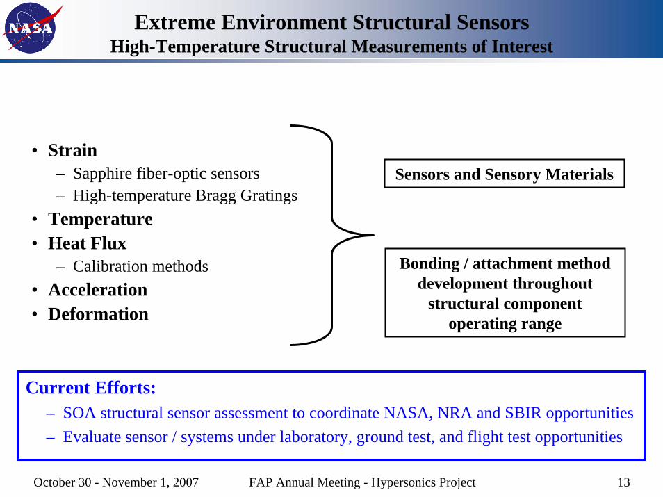
Extreme Environment Structural SensorsHigh-Temperature Structural Measurements of Interest
• Strain– Sapphire fiber-optic sensors– High-temperature Bragg Gratings
• Temperature• Heat Flux
– Calibration methods• Acceleration• Deformation
Sensors and Sensory Materials
Bonding / attachment method development throughout
structural component operating range
Current Efforts:– SOA structural sensor assessment to coordinate NASA, NRA and SBIR opportunities– Evaluate sensor / systems under laboratory, ground test, and flight test opportunities
October 30 - November 1, 2007 FAP Annual Meeting - Hypersonics Project 14
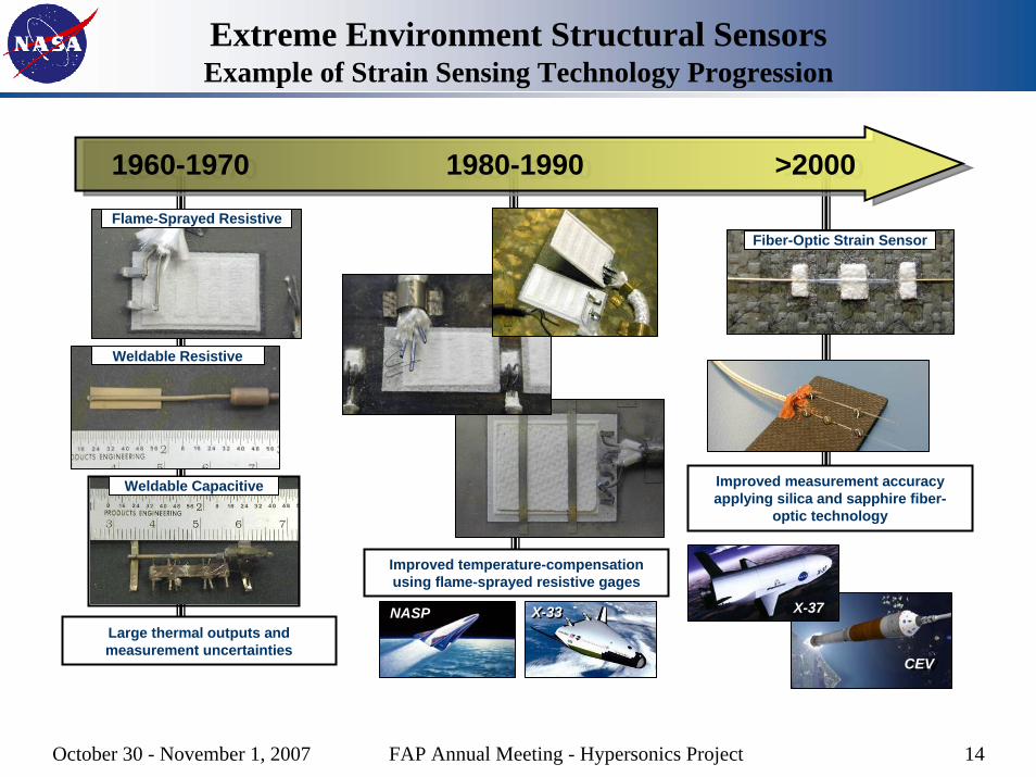
Extreme Environment Structural SensorsExample of Strain Sensing Technology Progression
Weldable Capacitive
Weldable Resistive
1960-1970 1980-1990 >20001960-1970 1980-1990 >2000
Large thermal outputs and measurement uncertainties
Improved temperature-compensation using flame-sprayed resistive gages
X-33X-33NASP
Improved measurement accuracy applying silica and sapphire fiber-
optic technology
X-37
CEVCEV
Flame-Sprayed ResistiveFiber-Optic Strain Sensor
October 30 - November 1, 2007 FAP Annual Meeting - Hypersonics Project 15
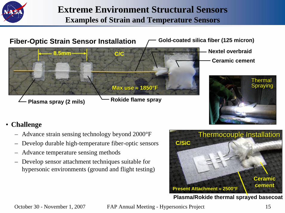
Extreme Environment Structural Sensors Examples of Strain and Temperature Sensors
ThermalSprayingThermalSpraying
Nextel overbraidCeramic cement
Gold-coated silica fiber (125 micron)
8.5mm
Rokide flame sprayPlasma spray (2 mils)
Fiber-Optic Strain Sensor Installation
Max use ≈ 1850°FMax use ≈ 1850°F
C/C
• Challenge– Advance strain sensing technology beyond 2000°F– Develop durable high-temperature fiber-optic sensors– Advance temperature sensing methods– Develop sensor attachment techniques suitable for
hypersonic environments (ground and flight testing)
Thermocouple InstallationThermocouple Installation
Ceramiccement
Ceramiccement
Plasma/Rokide thermal sprayed basecoatPresent Attachment ≈ 2500°FPresent Attachment ≈ 2500°F
C/SiC
October 30 - November 1, 2007 FAP Annual Meeting - Hypersonics Project 16
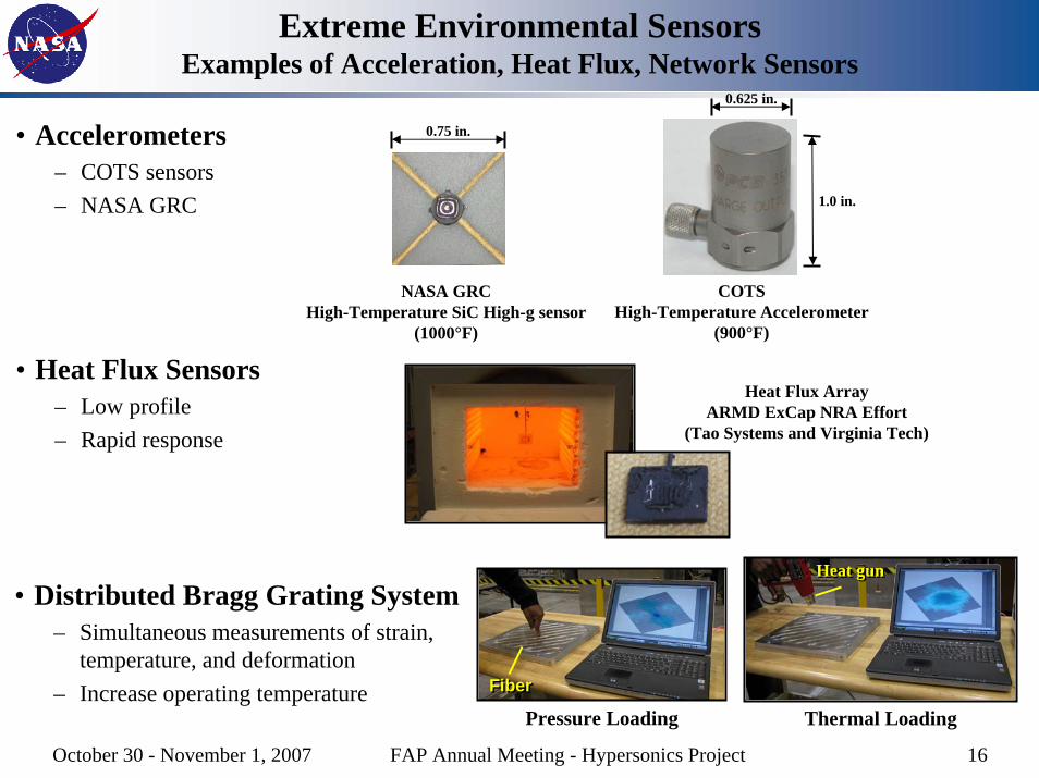
Extreme Environmental SensorsExamples of Acceleration, Heat Flux, Network Sensors
• Accelerometers– COTS sensors– NASA GRC
NASA GRCHigh-Temperature SiC High-g sensor
(1000°F)
0.75 in.
COTSHigh-Temperature Accelerometer
(900°F)
0.625 in.
1.0 in.
• Heat Flux Sensors– Low profile– Rapid response
Heat Flux ArrayARMD ExCap NRA Effort
(Tao Systems and Virginia Tech)
• Distributed Bragg Grating System– Simultaneous measurements of strain,
temperature, and deformation– Increase operating temperature
Pressure LoadingFiberFiber
Thermal Loading
Heat gunHeat gun
October 30 - November 1, 2007 FAP Annual Meeting - Hypersonics Project 17
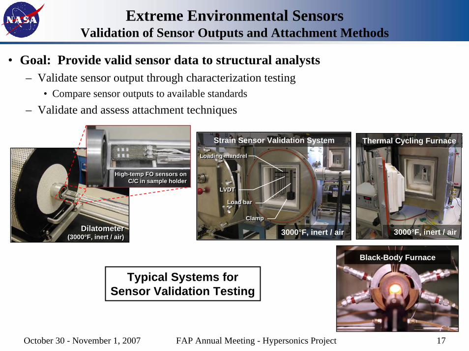
Extreme Environmental SensorsValidation of Sensor Outputs and Attachment Methods
• Goal: Provide valid sensor data to structural analysts– Validate sensor output through characterization testing
• Compare sensor outputs to available standards– Validate and assess attachment techniques
Dilatometer(3000°F, inert / air)
Dilatometer(3000°F, inert / air)
High-temp FO sensors on C/C in sample holder
High-temp FO sensors on C/C in sample holder
Strain Sensor Validation System
ClampClamp
Load barLoad bar
Loading mandrelLoading mandrel
LVDTLVDT
Thermal Cycling Furnace
3000°F, inert / air 3000°F, inert / air
Typical Systems forSensor Validation Testing
Black-Body Furnace
October 30 - November 1, 2007 FAP Annual Meeting - Hypersonics Project 18
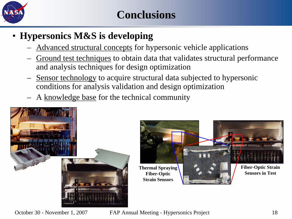
Conclusions
• Hypersonics M&S is developing– Advanced structural concepts for hypersonic vehicle applications– Ground test techniques to obtain data that validates structural performance
and analysis techniques for design optimization– Sensor technology to acquire structural data subjected to hypersonic
conditions for analysis validation and design optimization– A knowledge base for the technical community
Thermal Spraying Fiber-Optic
Strain Sensors
Fiber-Optic Strain Sensors in Test