Embed Size (px)
Citation preview
8/7/2019 Overview com
http://slidepdf.com/reader/full/overview-com 1/67
Nontraditional Machining and
Thermal Cutting Processes� Nontraditional machining refers to a group a processes
which removes excess material by various techniques
involving mechanical, thermal, electrical or chemical
energy� These processes do not use a sharp cutting tool in the
conventional sense

8/7/2019 Overview com
http://slidepdf.com/reader/full/overview-com 2/67
� Nontraditional processes have been developed in
response to new and unusual machining requirements,
including
± The need to machine newly developed materials with special
properties (high strength, high hardness, high toughness)
±
The need for unusual and/or complex geometries ± The need to avoid surface damage
8/7/2019 Overview com
http://slidepdf.com/reader/full/overview-com 3/67
� Classification of nontraditional manufacturing
processes by principle form of energy
± Mechanical - mechanical energy in some form different from
the action of a conventional cutting tool; erosion of the
workpiece material is typical
± Electrical - electrochemical energy to remove material

8/7/2019 Overview com
http://slidepdf.com/reader/full/overview-com 4/67
± Thermal - thermal energy generally applied to a small portion
of the work surface, causing removal by fusion and/or
vaporization; thermal energy is generated by conversion of
electrical energy
± Chemical - most materials are susceptible to chemical attack
by certain acids or other etchants; chemicals selectively remove
material from portions of the workpiece, while other portionsof the surface are protected

8/7/2019 Overview com
http://slidepdf.com/reader/full/overview-com 5/67
� Available nontraditional material removal processes
± Mechanical
� AFM - abrasive flow machining
� AJM - abrasive jet machining
� HDM - hydrodynamic machining
�
LSG - low stress grinding� RUM - rotary ultrasonic machining
� TAM - thermally assisted machining
� TFM - total form machining
� USM - ultrasonic machining
� WJM - water jet machining
8/7/2019 Overview com
http://slidepdf.com/reader/full/overview-com 6/67
± Electrical
� ECD - electrochemical deburring
� ECDG - electrochemical discharge grinding
� ECG - electrochemical grinding
� ECH - electrochemical honing
� ECM - electrochemical machining
� ECP - electrochemical polishing
� ECS - electrochemical sharpening
� ECT - electrochemical turning
� ES - electro-stream
� STEM - shaped tube electrolytic machining
8/7/2019 Overview com
http://slidepdf.com/reader/full/overview-com 7/67
± Thermal
� EBM - electron beam machining
� EDG - electrical discharge grinding
� EDM - electrical discharge machining
� EDS - electrical discharge sawing
� EDWC - electrical discharge wire cutting
� LBM - laser beam machining
� LBT - laser beam torch
� PBM - plasma beam machining

8/7/2019 Overview com
http://slidepdf.com/reader/full/overview-com 8/67
± Chemical
� CHM - chemical machining
� ELP - electropolish
� PCM - photochemical machining
� TCM - thermochemical machining
� TEM - thermal energy machining
� While many processes are available, only the most
commercially important processes are discussed here
8/7/2019 Overview com
http://slidepdf.com/reader/full/overview-com 9/67
Mechanical Energy Processes
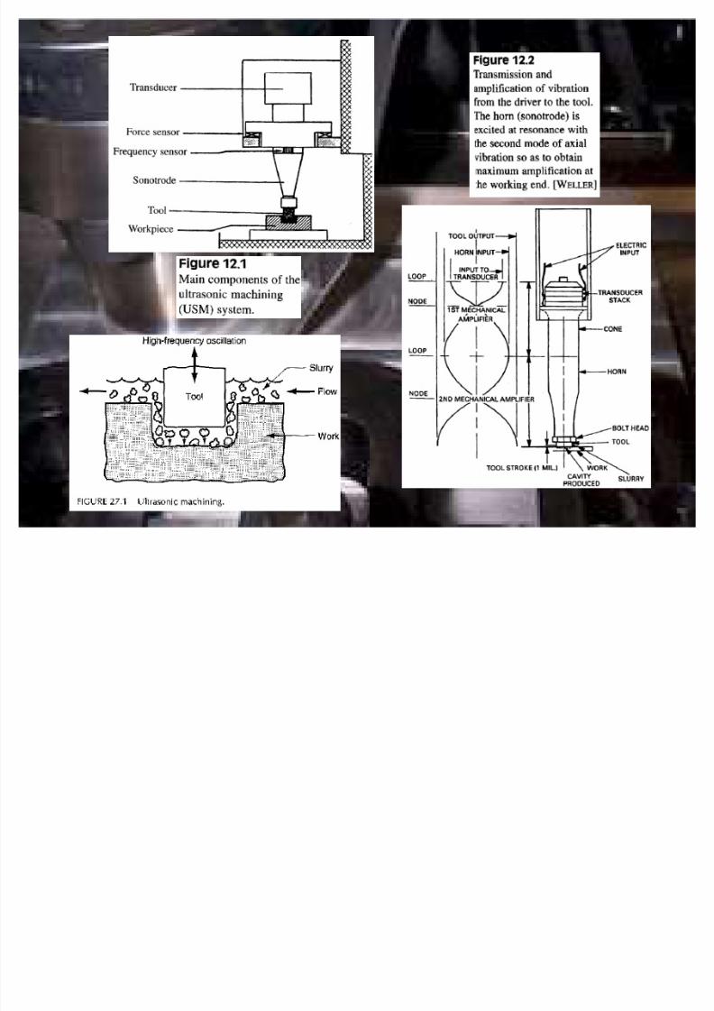
� Ultrasonic machining (USM)
± Abrasives contained in a slurry are driven at high velocity
against the work by a tool vibrating at low amplitude (.003in)
and high frequency (20-100khz)
± The tool oscillates in a direction perpendicular to the
workpiece surface and is fed slowly into the workpiece so that
the shape of the tool is formed in the part

8/7/2019 Overview com
http://slidepdf.com/reader/full/overview-com 10/67
± The action of the abrasives impinging against the work surface
performs the cutting ± Tool materials - soft steel, stainless steel
± Abrasive materials - boron nitride, boron carbide, aluminum
oxide, silicon carbide and diamond
± The vibration amplitude should be set approximately equal to
the grit size, and the gap size should be maintained at abouttwo times the grit size
8/7/2019 Overview com
http://slidepdf.com/reader/full/overview-com 11/67

8/7/2019 Overview com
http://slidepdf.com/reader/full/overview-com 12/67
± The ratio of work material to tool material removed during the
cutting process ranges from ~100:1 for cutting glass down to
~1:1 for cutting tool steel
± Workpiece materials: hard and brittle such as ceramics, glass
and carbides; successfully used on certain metals such as
stainless steel and titanium
± Shapes obtained by USM include nonround holes, holes along
a curved axis and coining operation, in which an image pattern
on the tool is imparted to a flat work surface
8/7/2019 Overview com
http://slidepdf.com/reader/full/overview-com 13/67
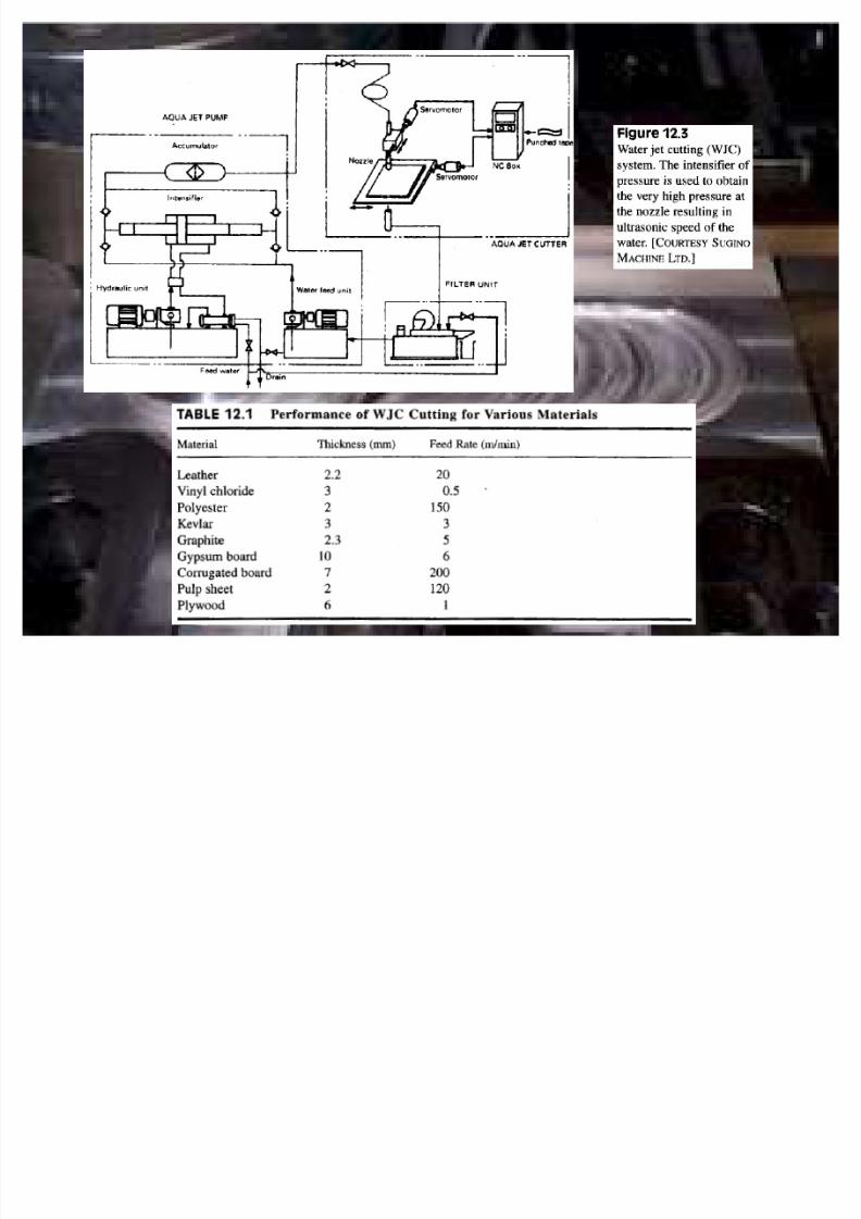
� Water jet cutting (WJC)
± Nozzle diameter: 0.004-0.016 in
± Pressure: up to 60,000psi
± Jet velocity: up to 3000 ft.Sec
± Nozzle made of sapphire, ruby or diamond
± Cutting fluids: polymer solutions; preferred because of their
tendency to produce a coherent stream

8/7/2019 Overview com
http://slidepdf.com/reader/full/overview-com 14/67
± Important process parameters: standoff distance, nozzle
operating diameter, water pressure and cutting feed rate
± Typical feed rates: 12 in/min to well over 1200 in/min
± The water jet cutting process is usually automated using CNC
robots to manipulate the nozzle unit along the desired
trajectory
± Materials cut by water jet: plastic, textile, composites, tiles,
carpet, leather and cardboard
8/7/2019 Overview com
http://slidepdf.com/reader/full/overview-com 15/67
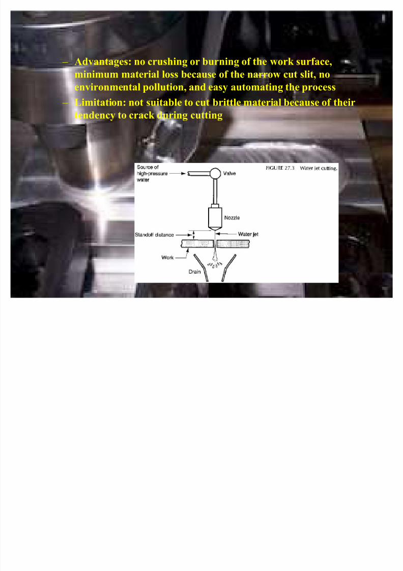
± Advantages: no crushing or burning of the work surface,
minimum material loss because of the narrow cut slit, noenvironmental pollution, and easy automating the process
± Limitation: not suitable to cut brittle material because of their
tendency to crack during cutting
8/7/2019 Overview com
http://slidepdf.com/reader/full/overview-com 16/67

8/7/2019 Overview com
http://slidepdf.com/reader/full/overview-com 17/67
� Abrasive water jet cutting (AWJC)
± Introduction of abrasive particles into the stream adds to the
number of parameters that must be controlled; among these
are: abrasive type, grit size and flow rate
± Type of abrasive materials: aluminum, oxide, silicon dioxide
and garnet (a silicate mineral)
± Grit size: ranges between 60 and 120
± Flow rate: approximately 0.5 lb/min
± Nozzle orifice diameter: 0.010 - 0.025in; somewhat larger that
in water jet cutting to permit higher flow rates and more
energy to be contained in the stream prior to the infection of
abrasives
8/7/2019 Overview com
http://slidepdf.com/reader/full/overview-com 18/67
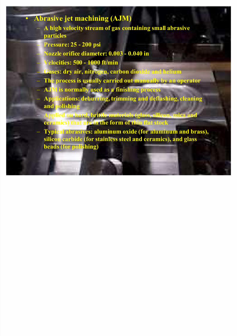
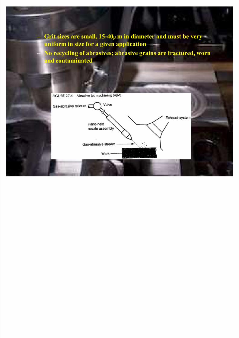
� Abrasive jet machining (AJM)
± A high velocity stream of gas containing small abrasive
particles
± Pressure: 25 - 200 psi
± Nozzle orifice diameter: 0.003 - 0.040 in
± Velocities: 500 - 1000 ft/min
± Gases: dry air, nitrogen, carbon dioxide and helium
±
The process is usually carried out manually by an operator ± AJM is normally used as a finishing process
± Applications: deburring, trimming and deflashing, cleaning
and polishing
± Applied on hard, brittle materials (glass, silicon, mica and
ceramics) that are in the form of thin flat stock ± Typical abrasives: aluminum oxide (for aluminum and brass),
silicon carbide (for stainless steel and ceramics), and glass
beads (for polishing)
8/7/2019 Overview com
http://slidepdf.com/reader/full/overview-com 19/67
± Grit sizes are small, 15-40Qm in diameter and must be very
uniform in size for a given application
± No recycling of abrasives; abrasive grains are fractured, worn
and contaminated
8/7/2019 Overview com
http://slidepdf.com/reader/full/overview-com 20/67
Electrochemical Machining Processes
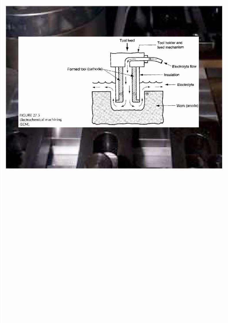
� Electrochemical machining (ECM)
± It removes metal from an electrically conductive workpiece by
anodic dissolution, in which the shape of the workpiece is
obtained by a formed electrode tool in close proximity to, butseparated from the work by a rapidly flowing electrolyte
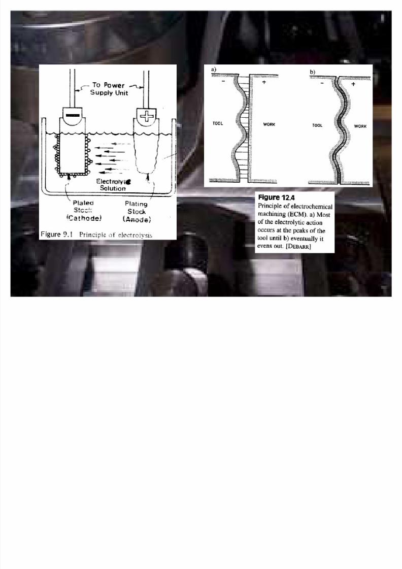
± Underlying principle: material is deplated from the anode and
deposited onto the cathode in the presence of an electrolyte
bath
8/7/2019 Overview com
http://slidepdf.com/reader/full/overview-com 21/67
8/7/2019 Overview com
http://slidepdf.com/reader/full/overview-com 22/67

8/7/2019 Overview com
http://slidepdf.com/reader/full/overview-com 23/67
± The difference in ECM is that the electrolyte bath flows
rapidly between the two poles to carry off the deplatedmaterial
± The electrode tool, usually made of copper, brass or stainless
steel, is designed to posses approximately the inverse of the
desired final shape of the part
±
Gap distance: usually from 0.003 - 0.030 in ± A water solution of sodium chloride is commonly used as the
electrolyte
8/7/2019 Overview com
http://slidepdf.com/reader/full/overview-com 24/67
± Electrolyte serves for:
� Carrying off the material that has been removed from theworkpiece
� Removing hear and hydrogen bubbles created in the
chemical reactions of the process
± Removed material in the form of microscopic particles must be
separated from the electrolyte through centrifuge,sedimentation or other means
± Large amount of electrical power is required to perform ECM

8/7/2019 Overview com
http://slidepdf.com/reader/full/overview-com 25/67
± Voltage is kept relatively low to minimize arcing across the gap
± Use when:
� The material is very hard or difficult to machine or
� Where the workpiece geometry is difficult or impossible
to accomplish by conventional machining methods
± Typical ECM applications
� Die sinking
� Multiple hole drilling
� Holes that are not round
� Deburring

8/7/2019 Overview com
http://slidepdf.com/reader/full/overview-com 26/67
± Advantages:
� Little surface damage to the work part
� No burrs as in conventional machining
� Low tool wear
� Relatively high metal removal rates for hard and
difficult to machine metals
± Disadvantages
� Significant cost of electrical power to drive the
operation
� Problems of disposing of the electrolyte sludge
8/7/2019 Overview com
http://slidepdf.com/reader/full/overview-com 27/67
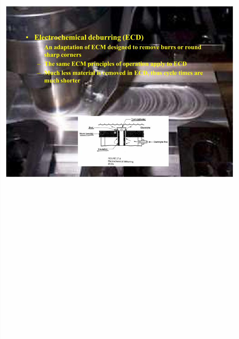
� Electrochemical deburring (ECD)
± An adaptation of ECM designed to remove burrs or round
sharp corners
± The same ECM principles of operation apply to ECD
± Much less material is removed in ECD, thus cycle times are
much shorter

8/7/2019 Overview com
http://slidepdf.com/reader/full/overview-com 28/67
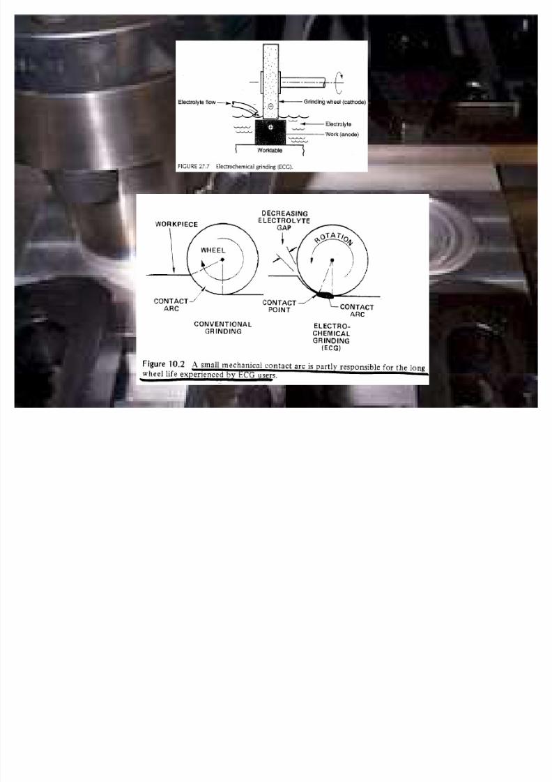
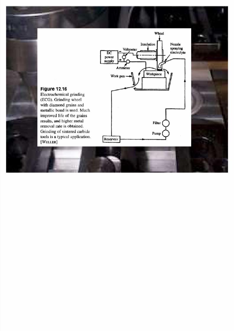
� Electrochemical grinding (ECG)
± Special form of ECM
± A rotating grinding wheel with a conductive bond material is
used to augment the anodic dissolution of the metal workpart
surface
± Bond material: metallic (diamond abrasives) or resin bond
impregnated with metal particles (aluminum oxide)
± Most of the machining is accomplished by electrochemical
action, therefore the grinding wheel lasts much longer
8/7/2019 Overview com
http://slidepdf.com/reader/full/overview-com 29/67
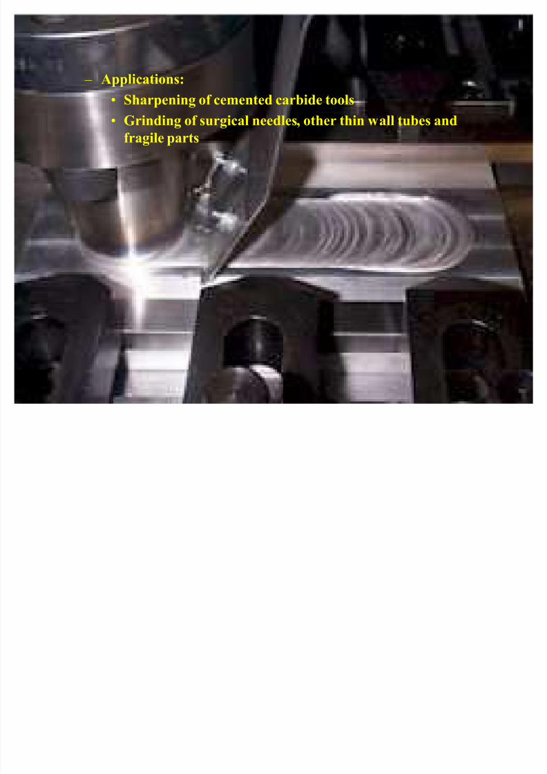
± Applications:
� Sharpening of cemented carbide tools
� Grinding of surgical needles, other thin wall tubes and
fragile parts
8/7/2019 Overview com
http://slidepdf.com/reader/full/overview-com 30/67
8/7/2019 Overview com
http://slidepdf.com/reader/full/overview-com 31/67
8/7/2019 Overview com
http://slidepdf.com/reader/full/overview-com 32/67
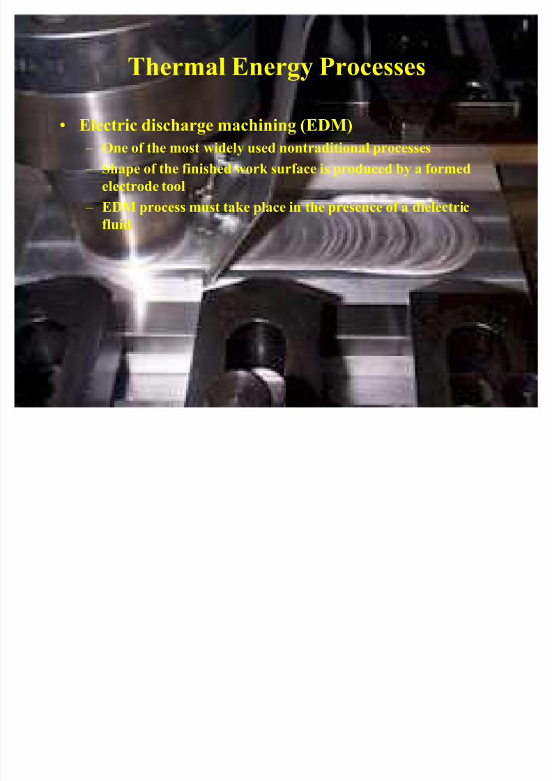
Thermal Energy Processes
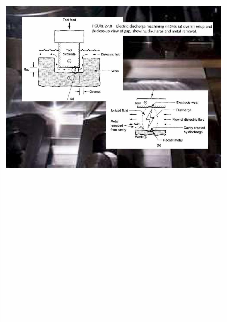
� Electric discharge machining (EDM)
± One of the most widely used nontraditional processes
± Shape of the finished work surface is produced by a formed
electrode tool
± EDM process must take place in the presence of a dielectric
fluid
8/7/2019 Overview com
http://slidepdf.com/reader/full/overview-com 33/67
8/7/2019 Overview com
http://slidepdf.com/reader/full/overview-com 34/67
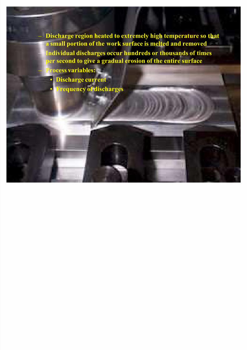
± Discharge region heated to extremely high temperature so that
a small portion of the work surface is melted and removed ± Individual discharges occur hundreds or thousands of times
per second to give a gradual erosion of the entire surface
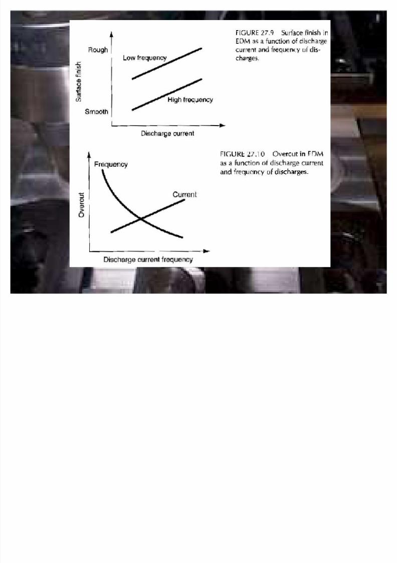
± Process variables:
� Discharge current
� Frequency of discharges
8/7/2019 Overview com
http://slidepdf.com/reader/full/overview-com 35/67
8/7/2019 Overview com
http://slidepdf.com/reader/full/overview-com 36/67
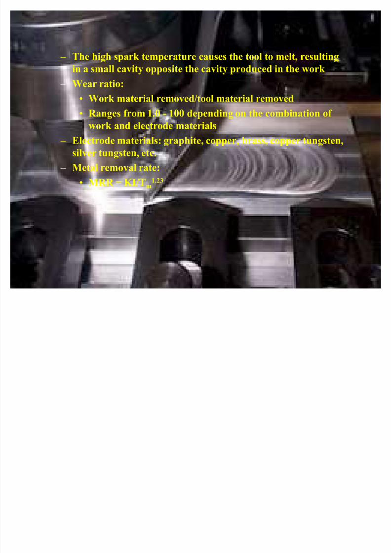
± The high spark temperature causes the tool to melt, resulting
in a small cavity opposite the cavity produced in the work ± Wear ratio:
� Work material removed/tool material removed
� Ranges from 1.0 - 100 depending on the combination of
work and electrode materials
± Electrode materials: graphite, copper, brass, copper tungsten,silver tungsten, etc.
± Metal removal rate:
� MRR = K I/Tm1.23
8/7/2019 Overview com
http://slidepdf.com/reader/full/overview-com 37/67
± Dielectric fluids used: hydrocarbon oils, kerosene and distilled
or deionized water ± Applications:
� tool fabrication and parts production
� delicate parts
� hole drilling with hole axis at an acute angle to the surface
� production machining of hard and exotic metals
8/7/2019 Overview com
http://slidepdf.com/reader/full/overview-com 38/67
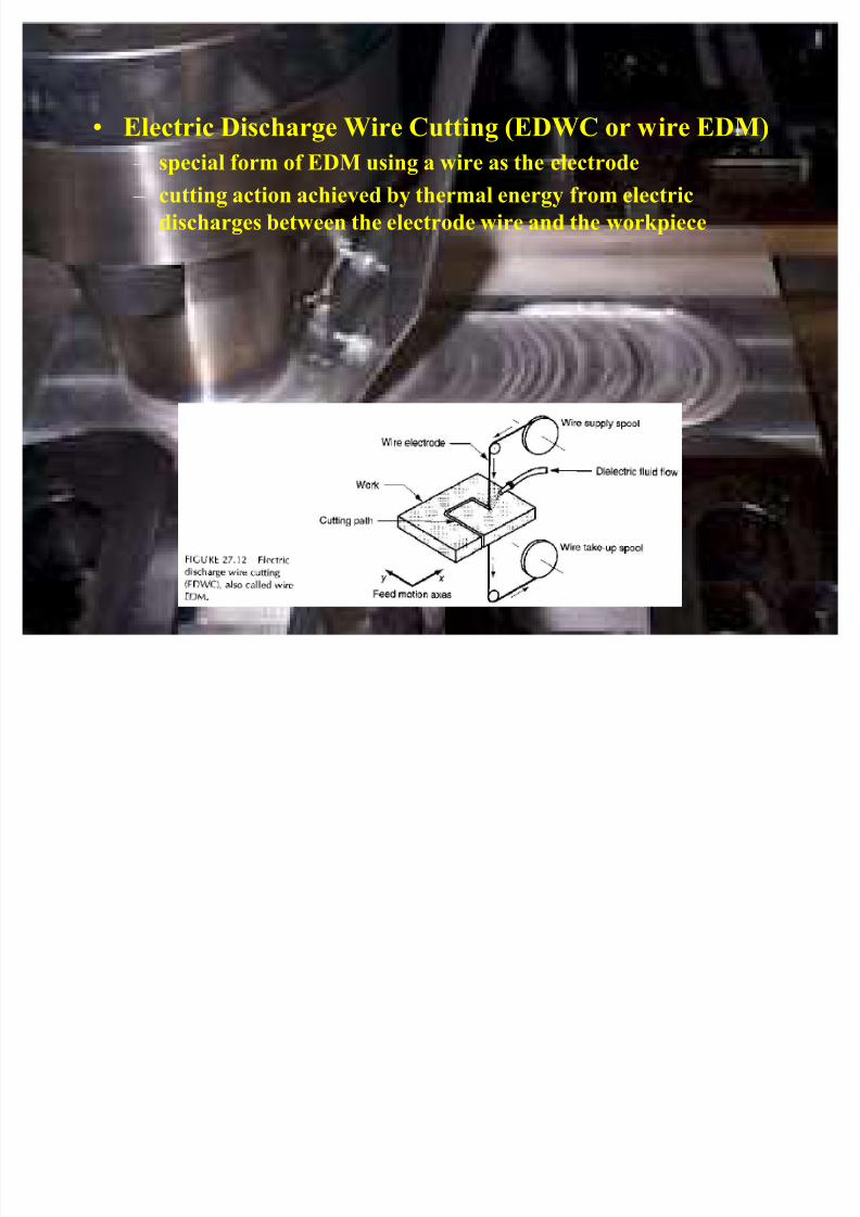
� Electric Discharge Wire Cutting (EDWC or wire EDM)
± special form of EDM using a wire as the electrode
± cutting action achieved by thermal energy from electric
discharges between the electrode wire and the workpiece

8/7/2019 Overview com
http://slidepdf.com/reader/full/overview-com 39/67
± Workpiece fed continuously and slowly past the wire to achieve
cutting path ± NC used to control workpart motions
± Wire EDM must be carried out in the presence of a dielectric
± Wire diameters: 0.003 - 0.012 in.
± Wire materials: brass, copper, tungsten and molybdenum
± Dielectric fluids: deionized water or oil
8/7/2019 Overview com
http://slidepdf.com/reader/full/overview-com 40/67
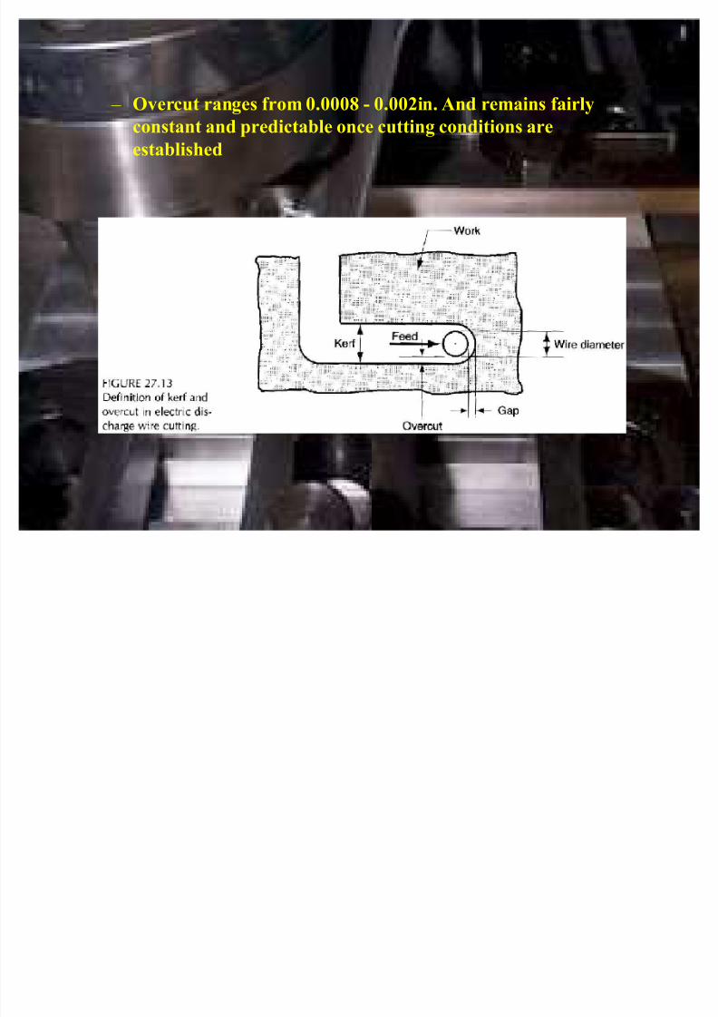
± Overcut ranges from 0.0008 - 0.002in.And remains fairly
constant and predictable once cutting conditions areestablished

8/7/2019 Overview com
http://slidepdf.com/reader/full/overview-com 41/67
� Electron Beam Machining (EBM)
± A high velocity stream of electrons is focused on the workpiecesurface to remove material by melting and vaporization
± Electron beam gun accelerates a stream of electrons to ~3/4 c
and focused through an electromagnetic lens
± Kinetic energy of beam converted to thermal energy of
extremely high density, melting or vaporizing material in avery localized area
± EBM must be carried out in a vacuum

8/7/2019 Overview com
http://slidepdf.com/reader/full/overview-com 42/67
± Can be used on any known material
± Applications:� drilling of extremely small diameter holes - down to 0.002
in
� drilling holes with high depth/diameter ratios, greater than
100:1
± Limitations:
� need of a vacuum
� high energy required
� expensive equipment

8/7/2019 Overview com
http://slidepdf.com/reader/full/overview-com 43/67
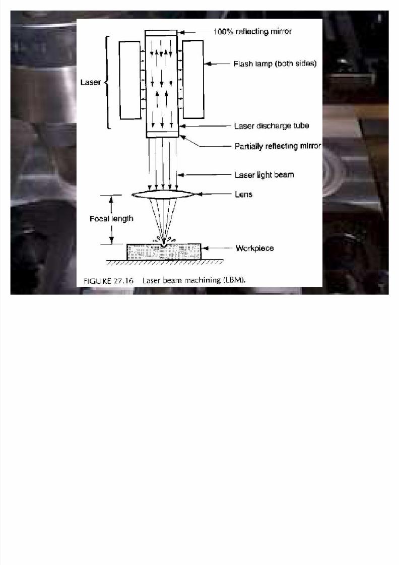
� Laser Beam Machining (LBM)
± Uses light energy from a laser to remove materials byvaporization and ablation
± Types of lasers:
� CO2
� solid-state
± Energy is concentrated optically and in terms of time
± Light beam pulsed so that the released energy results in an
impulse against the work surface, producing evaporation and
melting
8/7/2019 Overview com
http://slidepdf.com/reader/full/overview-com 44/67
± Used for:
� drilling - down to 0.001 in� slitting
� slotting
� scribing
� marking
± Not considered a mass production process; generally used on
thin stock
± Range of work materials virtually unlimited
8/7/2019 Overview com
http://slidepdf.com/reader/full/overview-com 45/67
8/7/2019 Overview com
http://slidepdf.com/reader/full/overview-com 46/67
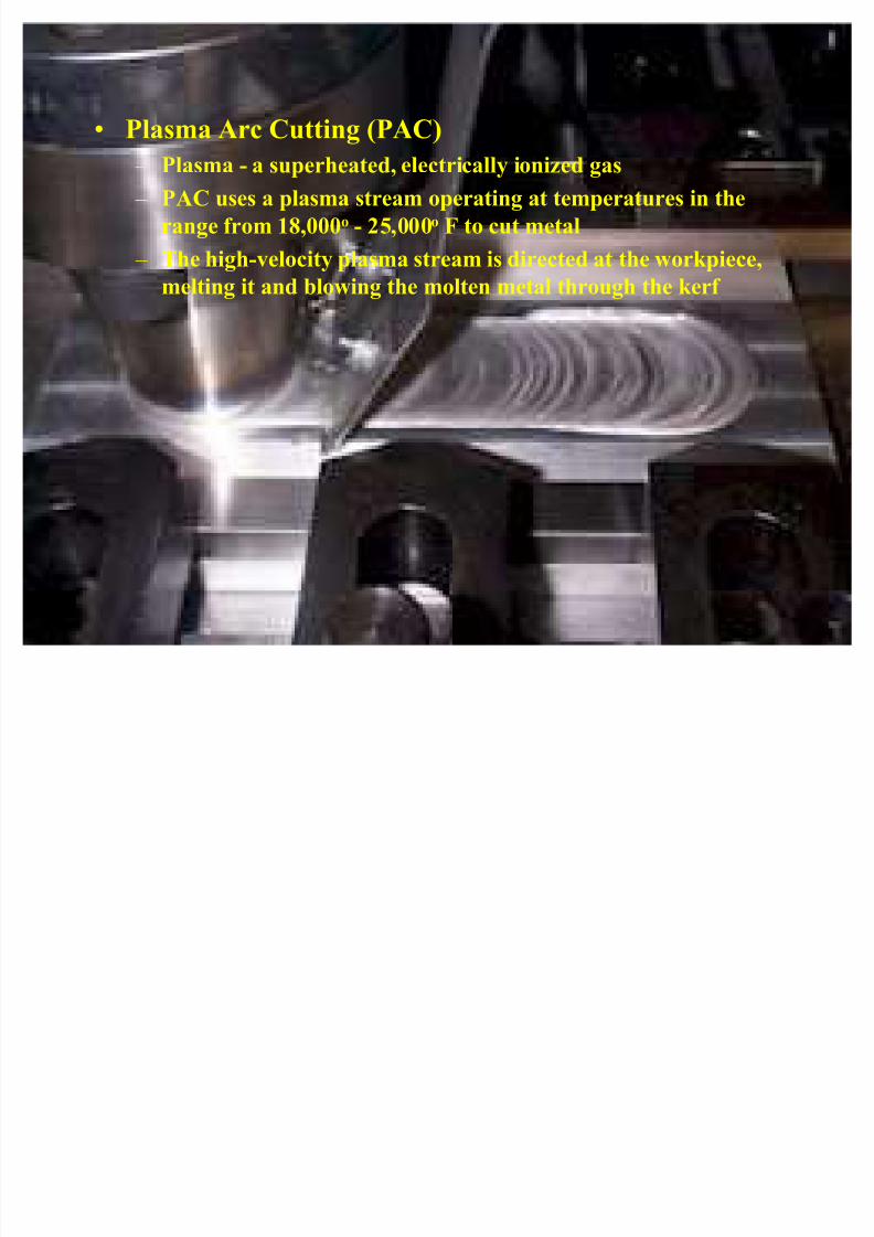
� Plasma Arc Cutting (PAC)
± Plasma - a superheated, electrically ionized gas
± PAC uses a plasma stream operating at temperatures in the
range from 18,000o - 25,000o F to cut metal
± The high-velocity plasma stream is directed at the workpiece,
melting it and blowing the molten metal through the kerf

8/7/2019 Overview com
http://slidepdf.com/reader/full/overview-com 47/67
± Plasma arc generated between an electrode inside the torch
± Plasma flows through a water-cooled nozzle, which constrictsand directs the stream
± Hot enough to cut through metal 6 in thick
± Gases used:
� nitrogen, argon-hydrogen or a mixture (primary gases)
� secondary gases or water directed to surround the plasma
jet to confine the arc and clean the kerf
8/7/2019 Overview com
http://slidepdf.com/reader/full/overview-com 48/67
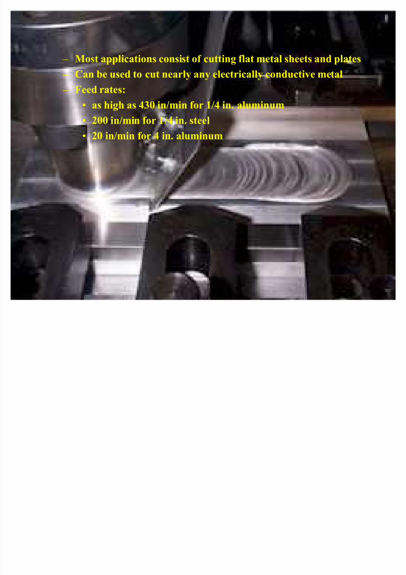
± Most applications consist of cutting flat metal sheets and plates
± Can be used to cut nearly any electrically conductive metal ± Feed rates:
� as high as 430 in/min for 1/4 in. aluminum
� 200 in/min for 1/4 in. steel
� 20 in/min for 4 in. aluminum
8/7/2019 Overview com
http://slidepdf.com/reader/full/overview-com 49/67
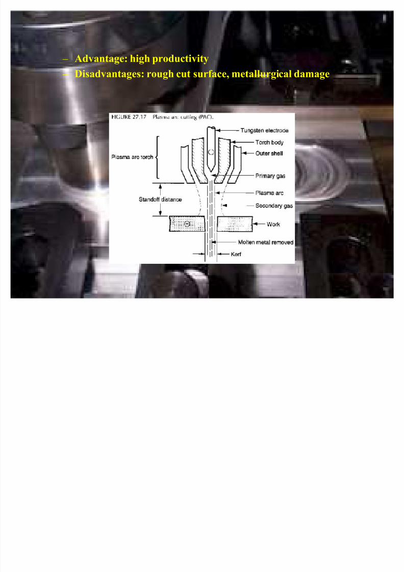
± Advantage: high productivity
± Disadvantages: rough cut surface, metallurgical damage
8/7/2019 Overview com
http://slidepdf.com/reader/full/overview-com 50/67
� Air Carbon Arc Cutting
± arc generated between a carbon electrode and the metallicwork
± High-velocity air jet used to blow away the melted portion of
the metal
± Used to form a kerf for severing the piece or to gouge a cavity
in the pat ± Used on a variety of metals, including cast iron, carbon steel,
low alloy and stainless steels
± Sputtering of molten metal is a hazard
8/7/2019 Overview com
http://slidepdf.com/reader/full/overview-com 51/67
� Other Arc Cutting Processes
± Gas metal arc cutting
± Shielded metal arc cutting
± Gas tungsten arc cutting
± Carbon arc cutting
8/7/2019 Overview com
http://slidepdf.com/reader/full/overview-com 52/67
Chemical Machining
� Mechanics and Chemistry of Chemical Machining
± Differences in applications and the ways in which the steps are
implemented account for the different forms of CHM; the
steps are
� Cleaning - to ensure that material will be removed
uniformly from the surfaces to be etched
8/7/2019 Overview com
http://slidepdf.com/reader/full/overview-com 53/67
� Masking - maskant, chemically resistant to the etchant,
applied to portions of the work surface not to be etched� Etching - the material removal step; part immersed in an
etchant that chemically attacks unmasked portions; part
removed and washed when desired amount of material has
been removed
�
Demasking - maskant removed from the part ± Masking and etching involve significant variations in methods,
materials and process parameters
8/7/2019 Overview com
http://slidepdf.com/reader/full/overview-com 54/67
± Maskant materials: neoprene, polyvinyl chloride, polyethylene
and other polymers ± Masking methods
� Cut and peel - performed by hand, used for large
workparts, low production quantities and where accuracy
is not a critical factor
�
Photographic resist - normally applied where small partsare produced in high quantities and close tolerances are
required
� Screen resist - used in applications that are between the
other two masking methods in terms of accuracy, part size
and production quantity
8/7/2019 Overview com
http://slidepdf.com/reader/full/overview-com 55/67
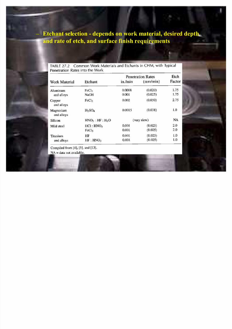
± Etchant selection - depends on work material, desired depth
and rate of etch, and surface finish requirements
8/7/2019 Overview com
http://slidepdf.com/reader/full/overview-com 56/67
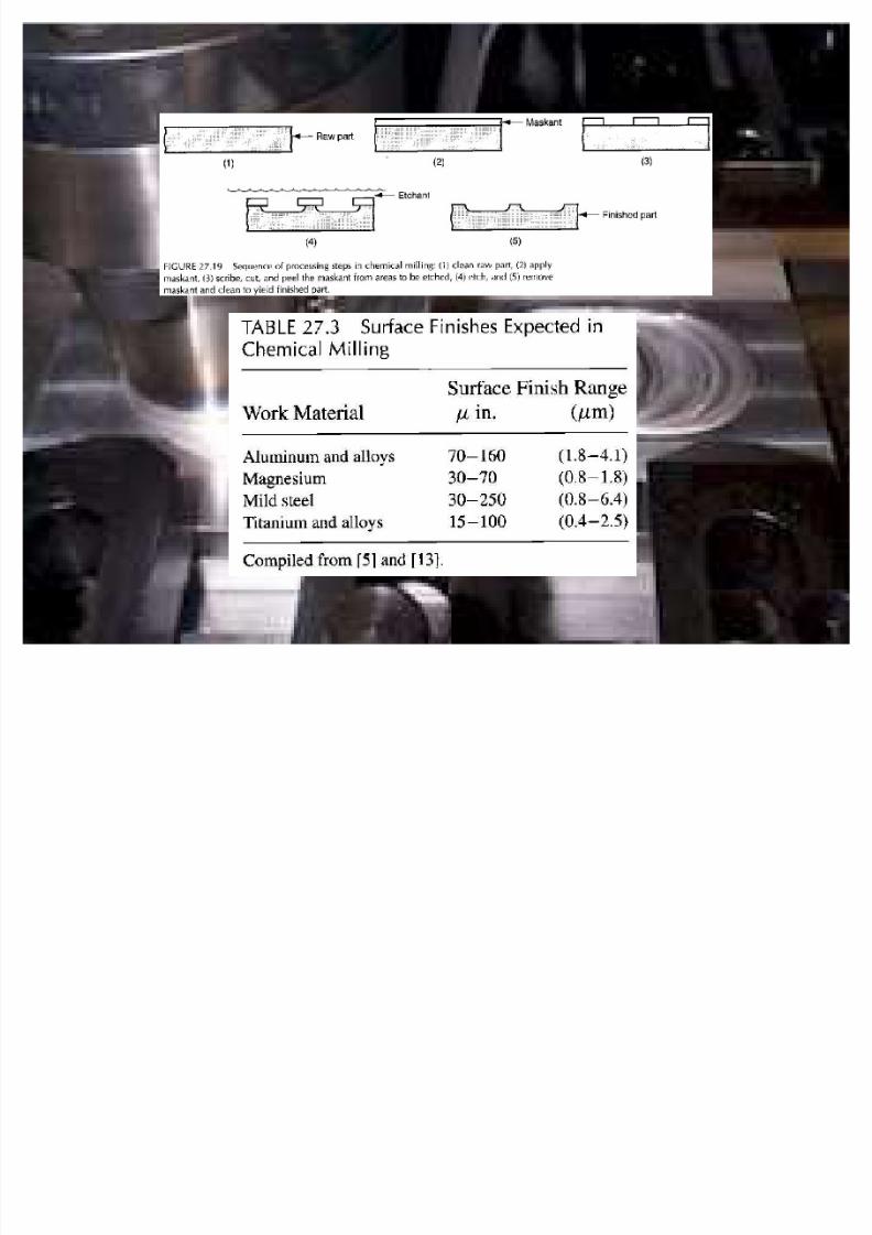
� Chemical Milling
± First CHM process to be commercialized
± Used largely in the aircraft industry
± Applicable to large parts where substantial amounts of metal
are removed
± Cut and peel maskant method employed
± As depth increases, surface finish becomes worse
± Metallurgical damage very small
8/7/2019 Overview com
http://slidepdf.com/reader/full/overview-com 57/67

8/7/2019 Overview com
http://slidepdf.com/reader/full/overview-com 58/67
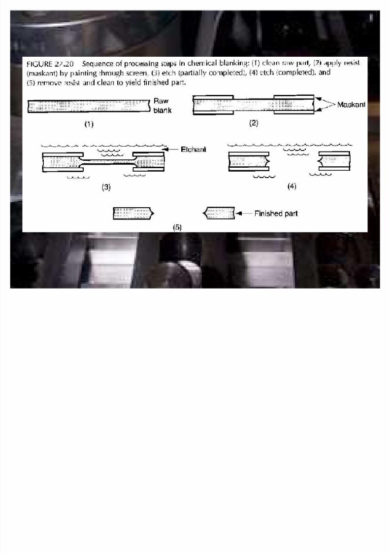
� Chemical Blanking
± Uses chemical erosion to cut very thin sheet-metal parts, downto 0.001 in. and/or for intricate cutting patterns
± Produces burr free parts
± Photoresist or screen resist method applied
± Maximum stock thickness ~0.030 in.
± Hardened or brittle materials can be processed
8/7/2019 Overview com
http://slidepdf.com/reader/full/overview-com 59/67

8/7/2019 Overview com
http://slidepdf.com/reader/full/overview-com 60/67
� Chemical Engraving
± A
chemical machining process used for making flat panels thathave lettering and/or artwork on one side
± Can be used to make raised or recessed lettering by reversing
the portions of the panel to be etched
± Masking done by either photoresist or screen resist methods
± Filling operation to apply paint or other coating followsetching

8/7/2019 Overview com
http://slidepdf.com/reader/full/overview-com 61/67
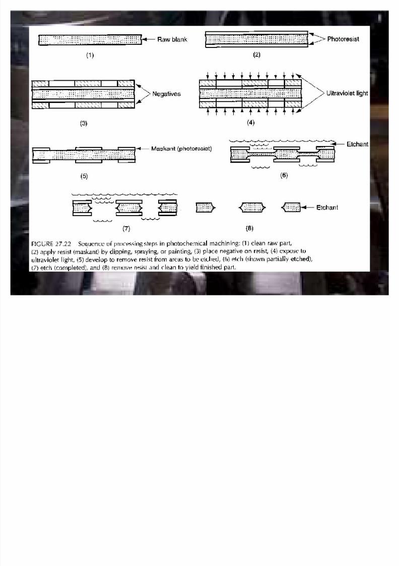
� Photochemical Machining (PCM)
±
Chemical machining in which the photoresist masking methodis used
± Employed in metalworking when close tolerances and/or
intricate patterns are required
± Used extensively in electronics industry (makes VLSI possible)
±
Photoresist materials in current use are sensitive to UV light,but not other wavelengths
8/7/2019 Overview com
http://slidepdf.com/reader/full/overview-com 62/67
± No need to carry out process in a darkroom
± Anisotropy: depth of cut d divided by undercut u; reciprocal of the etch factor
� A=1/Fe = d/u
� A: degree of anisotropy
� Fe: etch factor
8/7/2019 Overview com
http://slidepdf.com/reader/full/overview-com 63/67
8/7/2019 Overview com
http://slidepdf.com/reader/full/overview-com 64/67
Application Considerations
� Workpart Geometry Features
± Very small holes - (below 0.005 in. in diameter) use LBM
± Holes with large depth/diameter ratios - (d/D > 20) use
ECM and EDM
± Nonround holes - use EDM and ECM
± Narrow slots that are not straight - use EBM, LBM, wire
EDM, WJC and AWJC
8/7/2019 Overview com
http://slidepdf.com/reader/full/overview-com 65/67
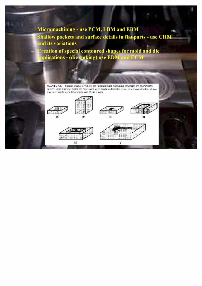
± Micromachining - use PCM, LBM and EBM
± Shallow pockets and surface details in flat parts - use CHMand its variations
± Creation of special contoured shapes for mold and die
applications - (die sinking) use EDM and ECM
8/7/2019 Overview com
http://slidepdf.com/reader/full/overview-com 66/67
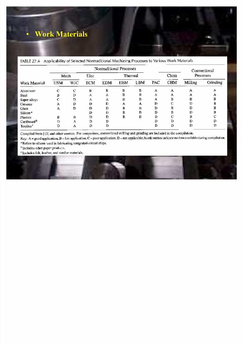
� Work Materials
8/7/2019 Overview com
http://slidepdf.com/reader/full/overview-com 67/67
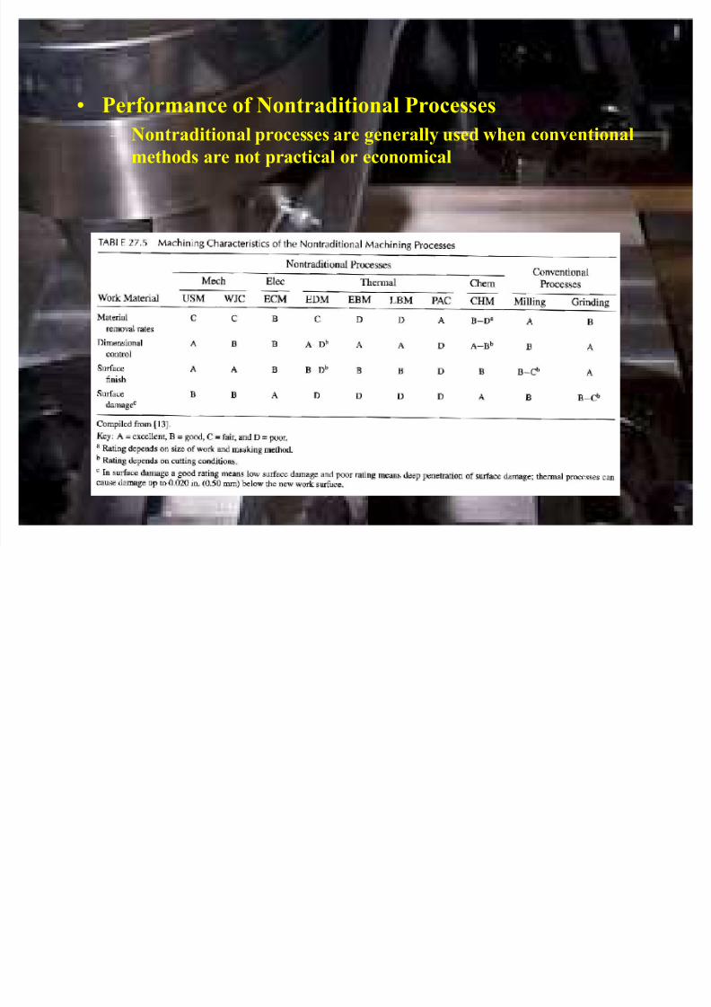
� Performance of Nontraditional Processes
± Nontraditional processes are generally used when conventionalmethods are not practical or economical
![roadmap for europe...figure 3.1 overview of fuel demand under COM and the e nrgy[ ] v oluti 26 figure 3.2 overview of additional fuel demand COM vs energy [r]evolution 27 figure 3.3](https://img.pdfslide.us/doc/110x75/5f82e6eeca316a64222a8308/roadmap-for-europe-figure-31-overview-of-fuel-demand-under-com-and-the-e-nrgy.jpg)