Embed Size (px)
Citation preview
1
Data Sheet
GF40Thermal Mass Flow
PrPrPrPrProduct Descriptionoduct Descriptionoduct Descriptionoduct Descriptionoduct Description
OverviewOverviewOverviewOverviewOverview
Elastomer SealDigital Mass Flow Controllers and Meters
Brooks® GF40 (elastomer seal) thermal mass flow controller (MFC) and thermal mass flowmeter (MFM) achieves unprecedented performance, reliability, and flexibility in many gasflow measurement and control applications.
At the heart of the GF40 is Brooks’ patented 4th generation MultiFloTM capable device.MultiFlo overcomes a long-standing limitation of many thermal MFCs – when changinggas types, a simple correction factor, such as the ratio of heat capacities between thecalibration gas and new gas, cannot account for accuracy-robbing viscosity and densitydifferences. The Brooks MultiFlo database is built on thousands of native gas runs toestablish correction functions that account for both thermal and physical differencesamong gases making the GF40 Series among the most accurate and flexible MFCs/MFMsavailable today.
The Brooks GF40 Series is the perfect choice for customers who use thermal mass flowcontrollers or thermal mass flow meters on a variety of gases, who need to change gastype frequently, or who need to re-range while preserving gas measurement and controlaccuracy. Some examples:
• OEMs will reduce the number of gas and range-specific MFCs that they inventory
• Solar, biotech, CVD, plasma, glass, web coating, nanotechnology, vacuum processingand similar large users of mass flow meters and mass flow controllers will greatlyreduce their gas- and range-specific spares inventory
• R&D, research, and laboratory users can quickly change experiment conditions andachieve much better actual process gas accuracy vs. traditional mass flow devices
MultiFlo programming is simple and fast – a new gas and range can be programmedunder 60 seconds plus the device can be programmed without removing it from serviceor disconnecting the device from any process or tool control system.
The Brooks GF40 Series features a corrosion-resistant Hastelloy C-22 sensor for durable,long-term operation. Sub-1 second settling times and 1% of set point accuracy ensurethat the GF40 will provide reliable flow measurement or flow control in demanding gasflow applications. The GF40 achieves excellent internal to external leak integrity forchallenging process gases as found in CVD, solar, and other processes. With a wide rangeof connector types, seal and seat materials, and digital and analog I/O options available,the GF40 represents an extremely powerful, yet easy, upgrade for existing MFCs or MFMs.
DS-TMF-GF40-MFC-engMay, 2017
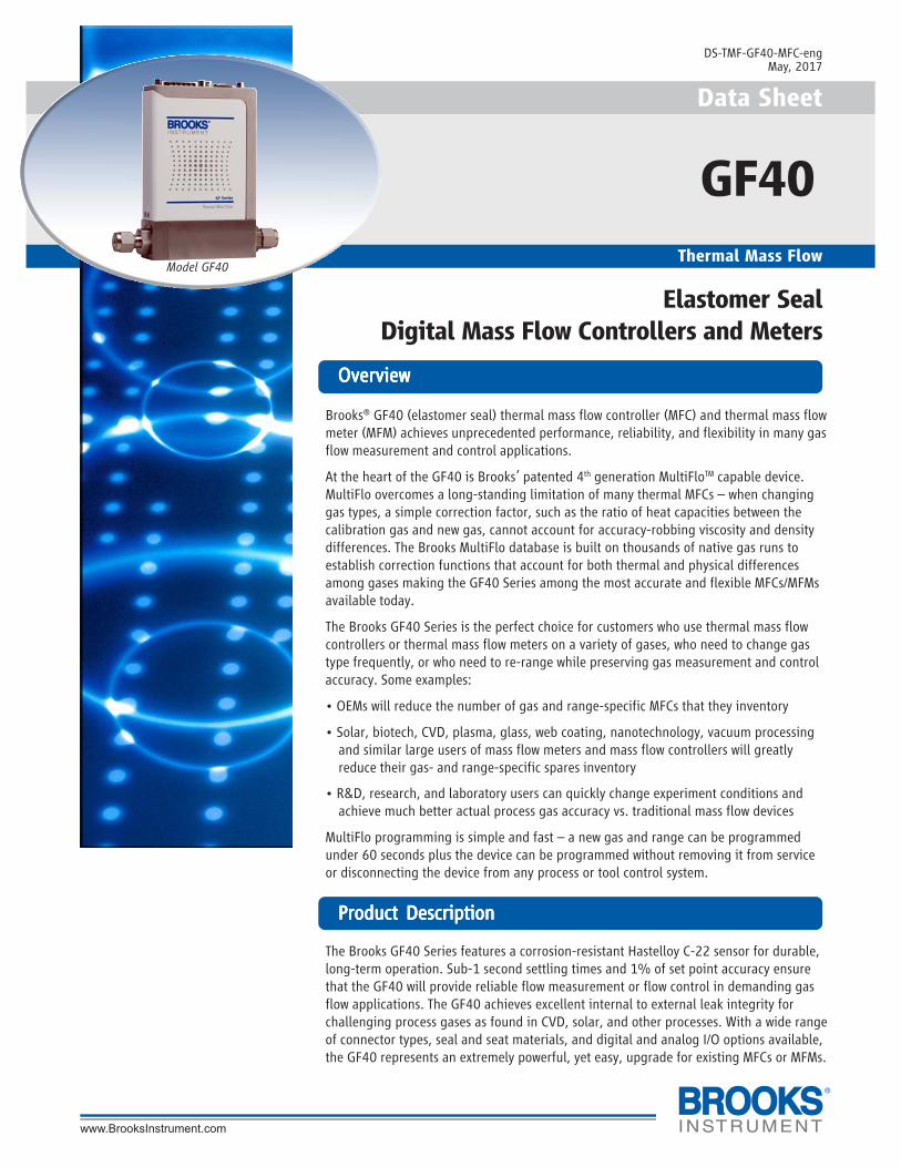
Model GF40
2
FeaturFeaturFeaturFeaturFeatureseseseses BenefitsBenefitsBenefitsBenefitsBenefits
Variety of Elastomer Seals Cost performance flexibility for a wide range of applications.
MultiFlo Gas and Range Programmabilty with Select new gas calibrations and full-scale ranges without the trouble and cost of removing the mass flowAdvanced Diagnostics and User Accessible Service Port controller from the gas line. Convenient interface to diagnostics port for maximum uptime.
Corrosion Resistant Hastelloy Sensor Provides unmatched long-term sensor stability ensuring maximum yield and throughput.
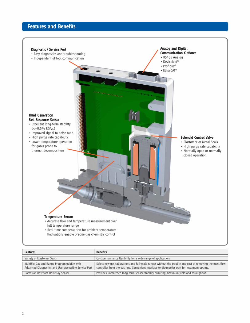
FeaturFeaturFeaturFeaturFeatures and Benefitses and Benefitses and Benefitses and Benefitses and Benefits
Analog and DigitalAnalog and DigitalAnalog and DigitalAnalog and DigitalAnalog and DigitalCommunication Options:Communication Options:Communication Options:Communication Options:Communication Options:• RS485 Analog• DeviceNetTM
• Profibus®
• EtherCAT®
Solenoid ConSolenoid ConSolenoid ConSolenoid ConSolenoid Contrtrtrtrtrol ol ol ol ol VVVVValvealvealvealvealve• Elastomer or Metal Seals• High purge rate capability• Normally open or normally
closed operation
TTTTTemperemperemperemperemperaturaturaturaturature Sensore Sensore Sensore Sensore Sensor• Accurate flow and temperature measurement over
full temperature range• Real-time compensation for ambient temperature
fluctuations enable precise gas chemistry control
Diagnostic / Service PDiagnostic / Service PDiagnostic / Service PDiagnostic / Service PDiagnostic / Service Portortortortort• Easy diagnostics and troubleshooting• Independent of tool communication
ThirThirThirThirThird Generd Generd Generd Generd GenerationationationationationFFFFFast Response Sensorast Response Sensorast Response Sensorast Response Sensorast Response Sensor• Excellent long-term stability
(<+0.5% F.S/yr.)• Improved signal to noise ratio• High purge rate capability• Lower temperature operation
for gases prone tothermal decomposition
3
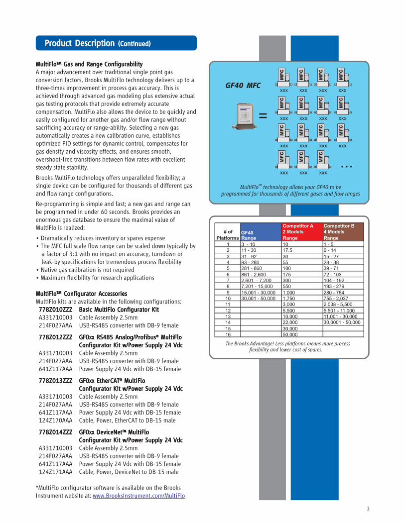
MultiFlo™ Gas and Range ConfigurabilityMultiFlo™ Gas and Range ConfigurabilityMultiFlo™ Gas and Range ConfigurabilityMultiFlo™ Gas and Range ConfigurabilityMultiFlo™ Gas and Range ConfigurabilityA major advancement over traditional single point gasconversion factors, Brooks MultiFlo technology delivers up to athree-times improvement in process gas accuracy. This isachieved through advanced gas modeling plus extensive actualgas testing protocols that provide extremely accuratecompensation. MultiFlo also allows the device to be quickly andeasily configured for another gas and/or flow range withoutsacrificing accuracy or range-ability. Selecting a new gasautomatically creates a new calibration curve, establishesoptimized PID settings for dynamic control, compensates forgas density and viscosity effects, and ensures smooth,overshoot-free transitions between flow rates with excellentsteady state stability.
Brooks MultiFlo technology offers unparalleled flexibility; asingle device can be configured for thousands of different gasand flow range configurations.
Re-programming is simple and fast; a new gas and range canbe programmed in under 60 seconds. Brooks provides anenormous gas database to ensure the maximal value ofMultiFlo is realized:
• Dramatically reduces inventory or spares expense• The MFC full scale flow range can be scaled down typically by
a factor of 3:1 with no impact on accuracy, turndown orleak-by specifications for tremendous process flexibility
• Native gas calibration is not required• Maximum flexibility for research applications
MultiFlo™ Configurator AccessoriesMultiFlo™ Configurator AccessoriesMultiFlo™ Configurator AccessoriesMultiFlo™ Configurator AccessoriesMultiFlo™ Configurator AccessoriesMultiFlo kits are available in the following configurations:778Z010ZZZ778Z010ZZZ778Z010ZZZ778Z010ZZZ778Z010ZZZ Basic MultiFlo Configurator KitBasic MultiFlo Configurator KitBasic MultiFlo Configurator KitBasic MultiFlo Configurator KitBasic MultiFlo Configurator KitA331710003 Cable Assembly 2.5mm214F027AAA USB-RS485 converter with DB-9 female
778Z012ZZZ778Z012ZZZ778Z012ZZZ778Z012ZZZ778Z012ZZZ GF0xx RS485 Analog/ProfibusGF0xx RS485 Analog/ProfibusGF0xx RS485 Analog/ProfibusGF0xx RS485 Analog/ProfibusGF0xx RS485 Analog/Profibus®®®®® MultiFlo MultiFlo MultiFlo MultiFlo MultiFloConfigurator Kit w/Power Supply 24 VdcConfigurator Kit w/Power Supply 24 VdcConfigurator Kit w/Power Supply 24 VdcConfigurator Kit w/Power Supply 24 VdcConfigurator Kit w/Power Supply 24 Vdc
A331710003 Cable Assembly 2.5mm214F027AAA USB-RS485 converter with DB-9 female641Z117AAA Power Supply 24 Vdc with DB-15 female
778Z013ZZZ778Z013ZZZ778Z013ZZZ778Z013ZZZ778Z013ZZZ GF0xx EtherCATGF0xx EtherCATGF0xx EtherCATGF0xx EtherCATGF0xx EtherCAT®®®®® MultiFlo MultiFlo MultiFlo MultiFlo MultiFloConfigurator Kit w/Power Supply 24 VdcConfigurator Kit w/Power Supply 24 VdcConfigurator Kit w/Power Supply 24 VdcConfigurator Kit w/Power Supply 24 VdcConfigurator Kit w/Power Supply 24 Vdc
A331710003 Cable Assembly 2.5mm214F027AAA USB-RS485 converter with DB-9 female641Z117AAA Power Supply 24 Vdc with DB-15 female124Z170AAA Cable, Power, EtherCAT to DB-15 male
778Z014ZZZ778Z014ZZZ778Z014ZZZ778Z014ZZZ778Z014ZZZ GF0xx DeviceNetGF0xx DeviceNetGF0xx DeviceNetGF0xx DeviceNetGF0xx DeviceNetTMTMTMTMTM MultiFlo MultiFlo MultiFlo MultiFlo MultiFloConfigurator Kit w/Power Supply 24 VdcConfigurator Kit w/Power Supply 24 VdcConfigurator Kit w/Power Supply 24 VdcConfigurator Kit w/Power Supply 24 VdcConfigurator Kit w/Power Supply 24 Vdc
A331710003 Cable Assembly 2.5mm214F027AAA USB-RS485 converter with DB-9 female641Z117AAA Power Supply 24 Vdc with DB-15 female124Z171AAA Cable, Power, DeviceNet to DB-15 male
*MultiFlo configurator software is available on the BrooksInstrument website at: www.BrooksInstrument.com/MultiFlo
PrPrPrPrProduct Description oduct Description oduct Description oduct Description oduct Description (Con(Con(Con(Con(Continued)tinued)tinued)tinued)tinued)
4
PrPrPrPrProduct Description oduct Description oduct Description oduct Description oduct Description (Con(Con(Con(Con(Continued)tinued)tinued)tinued)tinued)
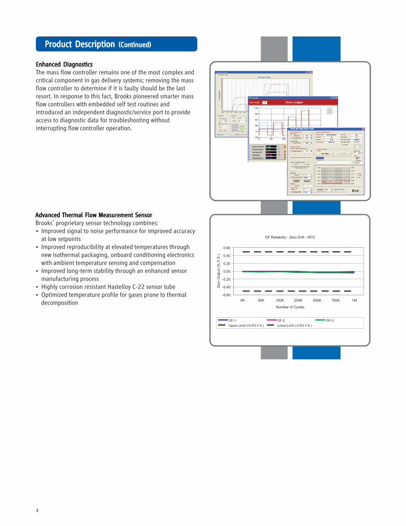
Enhanced DiagnosticsEnhanced DiagnosticsEnhanced DiagnosticsEnhanced DiagnosticsEnhanced DiagnosticsThe mass flow controller remains one of the most complex andcritical component in gas delivery systems; removing the massflow controller to determine if it is faulty should be the lastresort. In response to this fact, Brooks pioneered smarter massflow controllers with embedded self test routines andintroduced an independent diagnostic/service port to provideaccess to diagnostic data for troubleshooting withoutinterrupting flow controller operation.
Advanced Thermal Flow Measurement SensorAdvanced Thermal Flow Measurement SensorAdvanced Thermal Flow Measurement SensorAdvanced Thermal Flow Measurement SensorAdvanced Thermal Flow Measurement SensorBrooks’ proprietary sensor technology combines:• Improved signal to noise performance for improved accuracy
at low setpoints• Improved reproducibility at elevated temperatures through
new isothermal packaging, onboard conditioning electronicswith ambient temperature sensing and compensation
• Improved long-term stability through an enhanced sensormanufacturing process
• Highly corrosion resistant Hastelloy C-22 sensor tube• Optimized temperature profile for gases prone to thermal
decomposition
5
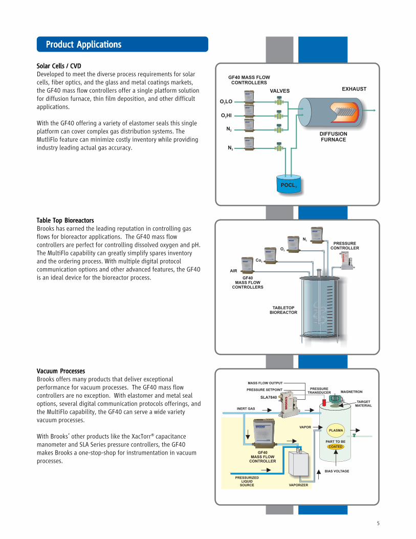
Vacuum ProcessesVacuum ProcessesVacuum ProcessesVacuum ProcessesVacuum ProcessesBrooks offers many products that deliver exceptionalperformance for vacuum processes. The GF40 mass flowcontrollers are no exception. With elastomer and metal sealoptions, several digital communication protocols offerings, andthe MultiFlo capability, the GF40 can serve a wide varietyvacuum processes.
With Brooks’ other products like the XacTorr® capacitancemanometer and SLA Series pressure controllers, the GF40makes Brooks a one-stop-shop for instrumentation in vacuumprocesses.
PrPrPrPrProduct oduct oduct oduct oduct ApplicationsApplicationsApplicationsApplicationsApplications
Solar Cells / CVDSolar Cells / CVDSolar Cells / CVDSolar Cells / CVDSolar Cells / CVDDeveloped to meet the diverse process requirements for solarcells, fiber optics, and the glass and metal coatings markets,the GF40 mass flow controllers offer a single platform solutionfor diffusion furnace, thin film deposition, and other difficultapplications.
With the GF40 offering a variety of elastomer seals this singleplatform can cover complex gas distribution systems. TheMutliFlo feature can minimize costly inventory while providingindustry leading actual gas accuracy.
Table Top BioreactorsTable Top BioreactorsTable Top BioreactorsTable Top BioreactorsTable Top BioreactorsBrooks has earned the leading reputation in controlling gasflows for bioreactor applications. The GF40 mass flowcontrollers are perfect for controlling dissolved oxygen and pH.The MultiFlo capability can greatly simplify spares inventoryand the ordering process. With multiple digital protocolcommunication options and other advanced features, the GF40is an ideal device for the bioreactor process.
6
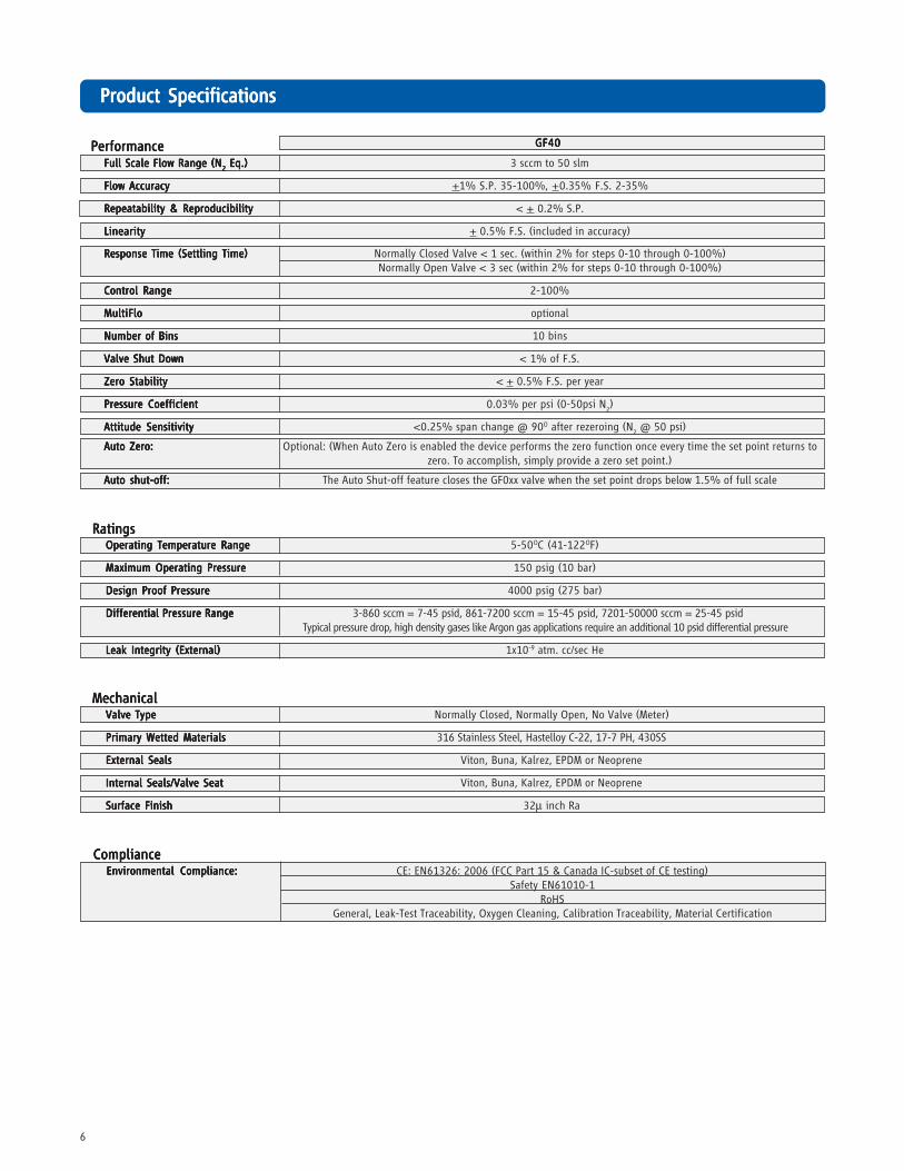
PrPrPrPrProduct Specificationsoduct Specificationsoduct Specificationsoduct Specificationsoduct Specifications
GF40GF40GF40GF40GF40
MechanicalMechanicalMechanicalMechanicalMechanicalValve TypeValve TypeValve TypeValve TypeValve Type Normally Closed, Normally Open, No Valve (Meter)
Primary Wetted MaterialsPrimary Wetted MaterialsPrimary Wetted MaterialsPrimary Wetted MaterialsPrimary Wetted Materials 316 Stainless Steel, Hastelloy C-22, 17-7 PH, 430SS
External SealsExternal SealsExternal SealsExternal SealsExternal Seals Viton, Buna, Kalrez, EPDM or Neoprene
Internal Seals/Valve SeatInternal Seals/Valve SeatInternal Seals/Valve SeatInternal Seals/Valve SeatInternal Seals/Valve Seat Viton, Buna, Kalrez, EPDM or Neoprene
Surface FinishSurface FinishSurface FinishSurface FinishSurface Finish 32μ inch Ra
RatingsRatingsRatingsRatingsRatingsOperating Temperature RangeOperating Temperature RangeOperating Temperature RangeOperating Temperature RangeOperating Temperature Range 5-50OC (41-122OF)
Maximum Operating PressureMaximum Operating PressureMaximum Operating PressureMaximum Operating PressureMaximum Operating Pressure 150 psig (10 bar)
Design Proof PressureDesign Proof PressureDesign Proof PressureDesign Proof PressureDesign Proof Pressure 4000 psig (275 bar)
Differential Pressure RangeDifferential Pressure RangeDifferential Pressure RangeDifferential Pressure RangeDifferential Pressure Range 3-860 sccm = 7-45 psid, 861-7200 sccm = 15-45 psid, 7201-50000 sccm = 25-45 psid Typical pressure drop, high density gases like Argon gas applications require an additional 10 psid differential pressure
Leak Integrity (External)Leak Integrity (External)Leak Integrity (External)Leak Integrity (External)Leak Integrity (External) 1x10⁻⁹ atm. cc/sec He
PerformancePerformancePerformancePerformancePerformanceFull Scale Flow Range (NFull Scale Flow Range (NFull Scale Flow Range (NFull Scale Flow Range (NFull Scale Flow Range (N
22222 Eq.) Eq.) Eq.) Eq.) Eq.) 3 sccm to 50 slm
Flow AccuracyFlow AccuracyFlow AccuracyFlow AccuracyFlow Accuracy +1% S.P. 35-100%, +0.35% F.S. 2-35%
Repeatability & ReproducibilityRepeatability & ReproducibilityRepeatability & ReproducibilityRepeatability & ReproducibilityRepeatability & Reproducibility < + 0.2% S.P.
LinearityLinearityLinearityLinearityLinearity + 0.5% F.S. (included in accuracy)
Response Time (Settling Time)Response Time (Settling Time)Response Time (Settling Time)Response Time (Settling Time)Response Time (Settling Time) Normally Closed Valve < 1 sec. (within 2% for steps 0-10 through 0-100%)Normally Open Valve < 3 sec (within 2% for steps 0-10 through 0-100%)
Control RangeControl RangeControl RangeControl RangeControl Range 2-100%
MultiFloMultiFloMultiFloMultiFloMultiFlo optional
Number of BinsNumber of BinsNumber of BinsNumber of BinsNumber of Bins 10 bins
Valve Shut DownValve Shut DownValve Shut DownValve Shut DownValve Shut Down < 1% of F.S.
Zero StabilityZero StabilityZero StabilityZero StabilityZero Stability < + 0.5% F.S. per year
Pressure CoefficientPressure CoefficientPressure CoefficientPressure CoefficientPressure Coefficient 0.03% per psi (0-50psi N2)
Attitude SensitivityAttitude SensitivityAttitude SensitivityAttitude SensitivityAttitude Sensitivity <0.25% span change @ 90O after rezeroing (N2 @ 50 psi)
Auto Zero:Auto Zero:Auto Zero:Auto Zero:Auto Zero: Optional: (When Auto Zero is enabled the device performs the zero function once every time the set point returns tozero. To accomplish, simply provide a zero set point.)
Auto shut-off:Auto shut-off:Auto shut-off:Auto shut-off:Auto shut-off: The Auto Shut-off feature closes the GF0xx valve when the set point drops below 1.5% of full scale
ComplianceComplianceComplianceComplianceComplianceEnvironmental Compliance:Environmental Compliance:Environmental Compliance:Environmental Compliance:Environmental Compliance: CE: EN61326: 2006 (FCC Part 15 & Canada IC-subset of CE testing)
Safety EN61010-1RoHS
General, Leak-Test Traceability, Oxygen Cleaning, Calibration Traceability, Material Certification
7
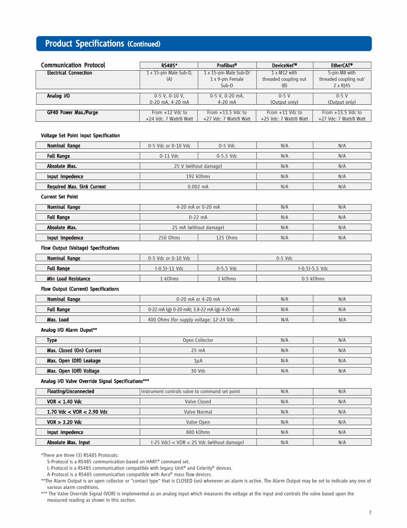
PrPrPrPrProduct Specifications oduct Specifications oduct Specifications oduct Specifications oduct Specifications (Con(Con(Con(Con(Continued)tinued)tinued)tinued)tinued)
Communication ProtocolCommunication ProtocolCommunication ProtocolCommunication ProtocolCommunication Protocol RS485*RS485*RS485*RS485*RS485* ProfibusProfibusProfibusProfibusProfibus®®®®® DeviceNetDeviceNetDeviceNetDeviceNetDeviceNetTMTMTMTMTM EtherCATEtherCATEtherCATEtherCATEtherCAT®®®®®
Electrical ConnectionElectrical ConnectionElectrical ConnectionElectrical ConnectionElectrical Connection 1 x 15-pin Male Sub-D, 1 x 15-pin Male Sub-D/ 1 x M12 with 5-pin M8 with(A) 1 x 9-pin Female threaded coupling nut threaded coupling nut/
Sub-D (B) 2 x RJ45
Analog I/OAnalog I/OAnalog I/OAnalog I/OAnalog I/O 0-5 V, 0-10 V, 0-5 V, 0-20 mA, 0-5 V 0-5 V0-20 mA, 4-20 mA 4-20 mA (Output only) (Output only)
GF40 Power Max./PurgeGF40 Power Max./PurgeGF40 Power Max./PurgeGF40 Power Max./PurgeGF40 Power Max./Purge From +12 Vdc to From +13.5 Vdc to From +11 Vdc to From +13.5 Vdc to+24 Vdc: 7 Watt/8 Watt +27 Vdc: 7 Watt/8 Watt +25 Vdc: 7 Watt/8 Watt +27 Vdc: 7 Watt/8 Watt
Voltage Set Point Input SpecificationVoltage Set Point Input SpecificationVoltage Set Point Input SpecificationVoltage Set Point Input SpecificationVoltage Set Point Input Specification
Nominal RangeNominal RangeNominal RangeNominal RangeNominal Range 0-5 Vdc or 0-10 Vdc 0-5 Vdc N/A N/A
Full RangeFull RangeFull RangeFull RangeFull Range 0-11 Vdc 0-5.5 Vdc N/A N/A
Absolute Max.Absolute Max.Absolute Max.Absolute Max.Absolute Max. 25 V (without damage) N/A N/A
Input ImpedenceInput ImpedenceInput ImpedenceInput ImpedenceInput Impedence 192 kOhms N/A N/A
Required Max. Sink CurrentRequired Max. Sink CurrentRequired Max. Sink CurrentRequired Max. Sink CurrentRequired Max. Sink Current 0.002 mA N/A N/A
Current Set PointCurrent Set PointCurrent Set PointCurrent Set PointCurrent Set Point
Nominal RangeNominal RangeNominal RangeNominal RangeNominal Range 4-20 mA or 0-20 mA N/A N/A
Full RangeFull RangeFull RangeFull RangeFull Range 0-22 mA N/A N/A
Absolute Max.Absolute Max.Absolute Max.Absolute Max.Absolute Max. 25 mA (without damage) N/A N/A
Input ImpedenceInput ImpedenceInput ImpedenceInput ImpedenceInput Impedence 250 Ohms 125 Ohms N/A N/A
Flow Output (Voltage) SpecificationsFlow Output (Voltage) SpecificationsFlow Output (Voltage) SpecificationsFlow Output (Voltage) SpecificationsFlow Output (Voltage) Specifications
Nominal RangeNominal RangeNominal RangeNominal RangeNominal Range 0-5 Vdc or 0-10 Vdc 0-5 Vdc
Full RangeFull RangeFull RangeFull RangeFull Range (-0.5)-11 Vdc 0-5.5 Vdc (-0.5)-5.5 Vdc
Min Load ResistanceMin Load ResistanceMin Load ResistanceMin Load ResistanceMin Load Resistance 1 kOhms 1 kOhms 0.5 kOhms
Flow Output (Current) SpecificationsFlow Output (Current) SpecificationsFlow Output (Current) SpecificationsFlow Output (Current) SpecificationsFlow Output (Current) Specifications
Nominal RangeNominal RangeNominal RangeNominal RangeNominal Range 0-20 mA or 4-20 mA N/A N/A
Full RangeFull RangeFull RangeFull RangeFull Range 0-22 mA (@ 0-20 mA); 3.8-22 mA (@ 4-20 mA) N/A N/A
Max. LoadMax. LoadMax. LoadMax. LoadMax. Load 400 Ohms (for supply voltage: 12-24 Vdc N/A N/A
Analog I/O Alarm Ouput**Analog I/O Alarm Ouput**Analog I/O Alarm Ouput**Analog I/O Alarm Ouput**Analog I/O Alarm Ouput**
TypeTypeTypeTypeType Open Collector N/A N/A
Max. Closed (On) CurrentMax. Closed (On) CurrentMax. Closed (On) CurrentMax. Closed (On) CurrentMax. Closed (On) Current 25 mA N/A N/A
Max. Open (Off) LeakageMax. Open (Off) LeakageMax. Open (Off) LeakageMax. Open (Off) LeakageMax. Open (Off) Leakage 1μA N/A N/A
Max. Open (Off) VoltageMax. Open (Off) VoltageMax. Open (Off) VoltageMax. Open (Off) VoltageMax. Open (Off) Voltage 30 Vdc N/A N/A
Analog I/O Valve Override Signal Specifications***Analog I/O Valve Override Signal Specifications***Analog I/O Valve Override Signal Specifications***Analog I/O Valve Override Signal Specifications***Analog I/O Valve Override Signal Specifications***
Floating/UnconnectedFloating/UnconnectedFloating/UnconnectedFloating/UnconnectedFloating/Unconnected Instrument controls valve to command set point N/A N/A
VOR < 1.40 VdcVOR < 1.40 VdcVOR < 1.40 VdcVOR < 1.40 VdcVOR < 1.40 Vdc Valve Closed N/A N/A
1.70 Vdc < VOR < 2.90 Vdc1.70 Vdc < VOR < 2.90 Vdc1.70 Vdc < VOR < 2.90 Vdc1.70 Vdc < VOR < 2.90 Vdc1.70 Vdc < VOR < 2.90 Vdc Valve Normal N/A N/A
VOR > 3.20 VdcVOR > 3.20 VdcVOR > 3.20 VdcVOR > 3.20 VdcVOR > 3.20 Vdc Valve Open N/A N/A
Input ImpedenceInput ImpedenceInput ImpedenceInput ImpedenceInput Impedence 800 kOhms N/A N/A
Absolute Max. InputAbsolute Max. InputAbsolute Max. InputAbsolute Max. InputAbsolute Max. Input (-25 Vdc) < VOR < 25 Vdc (without damage) N/A N/A
*There are three (3) RS485 Protocols:S-Protocol is a RS485 communication based on HART® command set.L-Protocol is a RS485 communication compatible with legacy Unit® and Celerity® devices.A-Protocol is a RS485 communication compatible with Aera® mass flow devices.
**The Alarm Output is an open collector or "contact type" that is CLOSED (on) whenever an alarm is active. The Alarm Output may be set to indicate any one ofvarious alarm conditions.
*** The Valve Override Signal (VOR) is implemented as an analog input which measures the voltage at the input and controls the valve based upon themeasured reading as shown in this section.
8
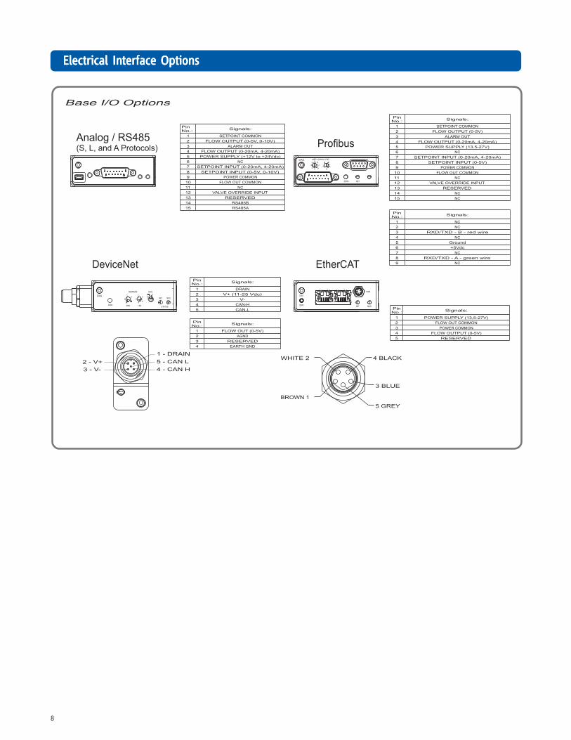
PrPrPrPrProduct Specificationsoduct Specificationsoduct Specificationsoduct Specificationsoduct SpecificationsElectrical InElectrical InElectrical InElectrical InElectrical Interface Optionsterface Optionsterface Optionsterface Optionsterface Options
9
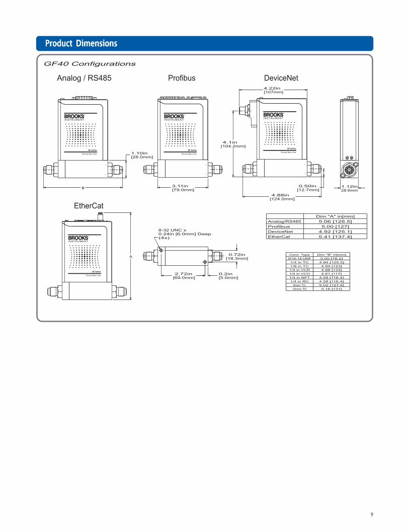
PrPrPrPrProduct Dimensionsoduct Dimensionsoduct Dimensionsoduct Dimensionsoduct Dimensions
10
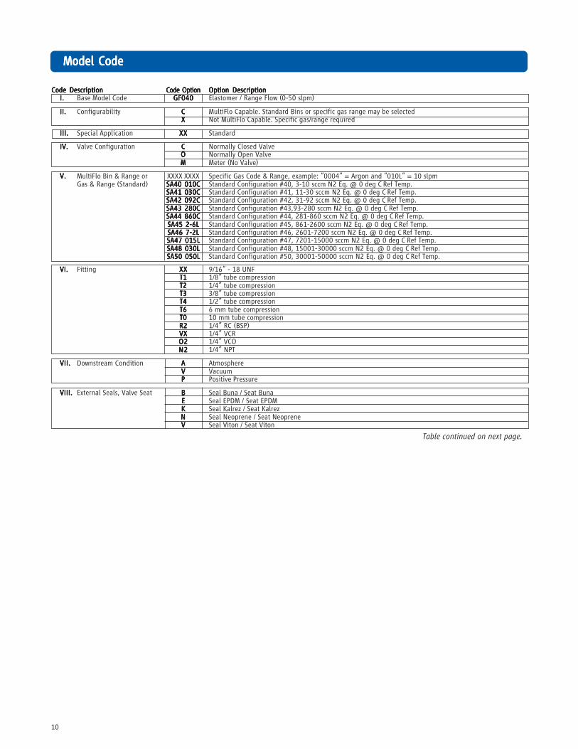
Model CodeModel CodeModel CodeModel CodeModel Code
Code DescriptionCode DescriptionCode DescriptionCode DescriptionCode Description Code OptionCode OptionCode OptionCode OptionCode Option Option DescriptionOption DescriptionOption DescriptionOption DescriptionOption DescriptionI.I.I.I.I. Base Model Code GF040GF040GF040GF040GF040 Elastomer / Range Flow (0-50 slpm)
II.II.II.II.II. Configurability CCCCC MultiFlo Capable. Standard Bins or specific gas range may be selectedXXXXX Not MultiFlo Capable. Specific gas/range required
III.III.III.III.III. Special Application XXXXXXXXXX Standard
IV.IV.IV.IV.IV. Valve Configuration CCCCC Normally Closed ValveOOOOO Normally Open ValveMMMMM Meter (No Valve)
V.V.V.V.V. MultiFlo Bin & Range or XXXX XXXX Specific Gas Code & Range, example: “0004” = Argon and “010L” = 10 slpmGas & Range (Standard) SA40 010CSA40 010CSA40 010CSA40 010CSA40 010C Standard Configuration #40, 3-10 sccm N2 Eq. @ 0 deg C Ref Temp.
SA41 030CSA41 030CSA41 030CSA41 030CSA41 030C Standard Configuration #41, 11-30 sccm N2 Eq. @ 0 deg C Ref Temp.SA42 092CSA42 092CSA42 092CSA42 092CSA42 092C Standard Configuration #42, 31-92 sccm N2 Eq. @ 0 deg C Ref Temp.SA43 280CSA43 280CSA43 280CSA43 280CSA43 280C Standard Configuration #43,93-280 sccm N2 Eq. @ 0 deg C Ref Temp.SA44 860CSA44 860CSA44 860CSA44 860CSA44 860C Standard Configuration #44, 281-860 sccm N2 Eq. @ 0 deg C Ref Temp.SA45 2-6LSA45 2-6LSA45 2-6LSA45 2-6LSA45 2-6L Standard Configuration #45, 861-2600 sccm N2 Eq. @ 0 deg C Ref Temp.SA46 7-2LSA46 7-2LSA46 7-2LSA46 7-2LSA46 7-2L Standard Configuration #46, 2601-7200 sccm N2 Eq. @ 0 deg C Ref Temp.SA47 015LSA47 015LSA47 015LSA47 015LSA47 015L Standard Configuration #47, 7201-15000 sccm N2 Eq. @ 0 deg C Ref Temp.SA48 030LSA48 030LSA48 030LSA48 030LSA48 030L Standard Configuration #48, 15001-30000 sccm N2 Eq. @ 0 deg C Ref Temp.SA50 050LSA50 050LSA50 050LSA50 050LSA50 050L Standard Configuration #50, 30001-50000 sccm N2 Eq. @ 0 deg C Ref Temp.
VI.VI.VI.VI.VI. Fitting XXXXXXXXXX 9/16” - 18 UNFT1T1T1T1T1 1/8” tube compressionT2T2T2T2T2 1/4” tube compressionT3T3T3T3T3 3/8” tube compressionT4T4T4T4T4 1/2” tube compressionT6T6T6T6T6 6 mm tube compressionT0T0T0T0T0 10 mm tube compressionR2R2R2R2R2 1/4” RC (BSP)VXVXVXVXVX 1/4” VCRO2O2O2O2O2 1/4” VCON2N2N2N2N2 1/4” NPT
VII.VII.VII.VII.VII. Downstream Condition AAAAA AtmosphereVVVVV VacuumPPPPP Positive Pressure
VIII.VIII.VIII.VIII.VIII. External Seals, Valve Seat BBBBB Seal Buna / Seat BunaEEEEE Seal EPDM / Seat EPDMKKKKK Seal Kalrez / Seat KalrezNNNNN Seal Neoprene / Seat NeopreneVVVVV Seal Viton / Seat Viton
Table continued on next page.
11
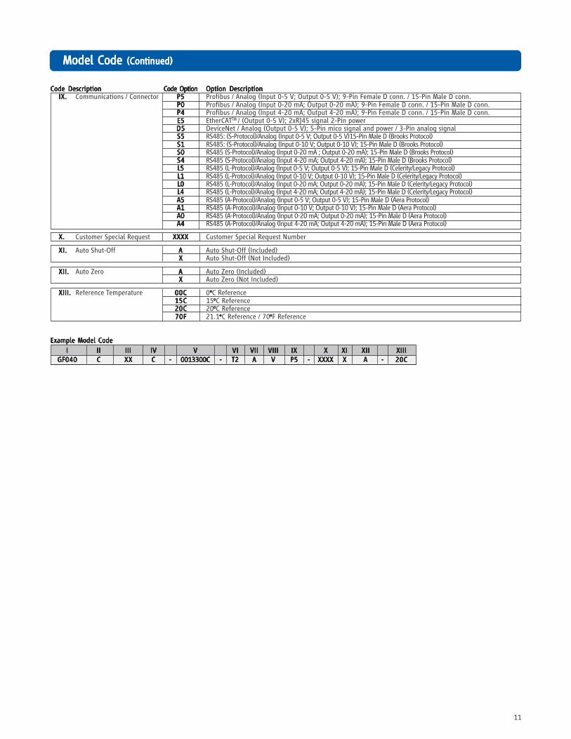
Code DescriptionCode DescriptionCode DescriptionCode DescriptionCode Description Code OptionCode OptionCode OptionCode OptionCode Option Option DescriptionOption DescriptionOption DescriptionOption DescriptionOption DescriptionIX.IX.IX.IX.IX. Communications / Connector P5P5P5P5P5 Profibus / Analog (Input 0-5 V; Output 0-5 V); 9-Pin Female D conn. / 15-Pin Male D conn.
P0P0P0P0P0 Profibus / Analog (Input 0-20 mA; Output 0-20 mA); 9-Pin Female D conn. / 15-Pin Male D conn.P4P4P4P4P4 Profibus / Analog (Input 4-20 mA; Output 4-20 mA); 9-Pin Female D conn. / 15-Pin Male D conn.E5E5E5E5E5 EtherCATTM / (Output 0-5 V); 2xRJ45 signal 2-Pin powerD5D5D5D5D5 DeviceNet / Analog (Output 0-5 V); 5-Pin mico signal and power / 3-Pin analog signalS5S5S5S5S5 RS485: (S-Protocol)/Analog (Input 0-5 V; Output 0-5 V)15-Pin Male D (Brooks Protocol)S1S1S1S1S1 RS485: (S-Protocol)/Analog (Input 0-10 V; Output 0-10 V); 15-Pin Male D (Brooks Protocol)S0S0S0S0S0 RS485 (S-Protocol)/Analog (Input 0-20 mA ; Output 0-20 mA); 15-Pin Male D (Brooks Protocol)S4S4S4S4S4 RS485 (S-Protocol)/Analog (Input 4-20 mA; Output 4-20 mA); 15-Pin Male D (Brooks Protocol)L5L5L5L5L5 RS485 (L-Protocol)/Analog (Input 0-5 V; Output 0-5 V); 15-Pin Male D (Celerity/Legacy Protocol)L1L1L1L1L1 RS485 (L-Protocol)/Analog (Input 0-10 V; Output 0-10 V); 15-Pin Male D (Celerity/Legacy Protocol)L0L0L0L0L0 RS485 (L-Protocol)/Analog (Input 0-20 mA; Output 0-20 mA); 15-Pin Male D (Celerity/Legacy Protocol)L4L4L4L4L4 RS485 (L-Protocol)/Analog (Input 4-20 mA; Output 4-20 mA); 15-Pin Male D (Celerity/Legacy Protocol)A5A5A5A5A5 RS485 (A-Protocol)/Analog (Input 0-5 V; Output 0-5 V); 15-Pin Male D (Aera Protocol)A1A1A1A1A1 RS485 (A-Protocol)/Analog (Input 0-10 V; Output 0-10 V); 15-Pin Male D (Aera Protocol)A0A0A0A0A0 RS485 (A-Protocol)/Analog (Input 0-20 mA; Output 0-20 mA); 15-Pin Male D (Aera Protocol)A4A4A4A4A4 RS485 (A-Protocol)/Analog (Input 4-20 mA; Output 4-20 mA); 15-Pin Male D (Aera Protocol)
X.X.X.X.X. Customer Special Request XXXXXXXXXXXXXXXXXXXX Customer Special Request Number
XI.XI.XI.XI.XI. Auto Shut-Off AAAAA Auto Shut-Off (Included)XXXXX Auto Shut-Off (Not Included)
XII.XII.XII.XII.XII. Auto Zero AAAAA Auto Zero (Included)XXXXX Auto Zero (Not Included)
XIII.XIII.XIII.XIII.XIII. Reference Temperature 00C00C00C00C00C 0oooooC Reference15C15C15C15C15C 15oooooC Reference20C20C20C20C20C 20oooooC Reference70F70F70F70F70F 21.1oooooC Reference / 70oooooF Reference
Example Model CodeExample Model CodeExample Model CodeExample Model CodeExample Model Code
IIIII IIIIIIIIII IIIIIIIIIIIIIII IVIVIVIVIV VVVVV VIVIVIVIVI VIIVIIVIIVIIVII VIIIVIIIVIIIVIIIVIII IXIXIXIXIX XXXXX XIXIXIXIXI XIIXIIXIIXIIXII XIIIXIIIXIIIXIIIXIIIGF040GF040GF040GF040GF040 CCCCC XXXXXXXXXX CCCCC ----- 0013300C0013300C0013300C0013300C0013300C ----- T2T2T2T2T2 AAAAA VVVVV P5P5P5P5P5 ----- XXXXXXXXXXXXXXXXXXXX XXXXX AAAAA ----- 20C20C20C20C20C
Model Code Model Code Model Code Model Code Model Code (Con(Con(Con(Con(Continued)tinued)tinued)tinued)tinued)

12
Brooks is committed to assuring all of our customers receive the ideal flow solution for their application, along with outstandingservice and support to back it up. We operate first class repair facilities located around the world to provide rapid response andsupport. Each location utilizes primary standard calibration equipment to ensure accuracy and reliability for repairs and recalibra-tion and is certified by our local Weights and Measures Authorities and traceable to the relevant International Standards.
Visit www.BrooksInstrument.com to locate the service location nearest to you.
STSTSTSTSTARARARARARTTTTT-UP SERVICE -UP SERVICE -UP SERVICE -UP SERVICE -UP SERVICE AND IN-SITU CALIBRAAND IN-SITU CALIBRAAND IN-SITU CALIBRAAND IN-SITU CALIBRAAND IN-SITU CALIBRATIONTIONTIONTIONTION
Brooks Instrument can provide start-up service prior to operation when required. For some process applications, where ISO-9001Quality Certification is important, it is mandatory to verify and/or (re)calibrate the products periodically. In many cases this servicecan be provided under in-situ conditions, and the results will be traceable to the relevant international quality standards.
CUSTCUSTCUSTCUSTCUSTOMER SEMINARS OMER SEMINARS OMER SEMINARS OMER SEMINARS OMER SEMINARS AND AND AND AND AND TRAININGTRAININGTRAININGTRAININGTRAINING
Brooks Instrument can provide customer seminars and dedicated training to engineers, end users, and maintenance persons.
Please contact your nearest sales representative for more details.
Due to Brooks Instrument's commitment to continuous improvement of our products, all specifications are subject to change without notice.
BrBrBrBrBrooks Service and Supportooks Service and Supportooks Service and Supportooks Service and Supportooks Service and Support
TRADEMARKSBrooks, Celerity, MultiFlo, XacTorr are marks of Brooks Instrument, LLCAll other marks are property of their respective owners.


![[PID] PID Control - Good Tuning - A Pocket Guide](https://img.pdfslide.us/doc/110x75/577d2a661a28ab4e1ea914b1/pid-pid-control-good-tuning-a-pocket-guide.jpg)


