Embed Size (px)
Citation preview
DESIGNING AND IMPLEMENTATION OF AN OPTIMIZED PID
CONTROLLER FOR LONGITUDINAL AUTOPILOT
ABSTRACT
This paper presents the design of an Aircraft model for
Longitudinal Dynamics. We formulated a design of inner
and outer loop of an aircraft with and without optimization
(PID controller) for continuous and discrete controller by
controlling the variables of an aircraft using a simulation
loop of a MATLAB. The different flight conditions were
arrived using Orthogonal Array (OA) based on different
Aircraft weight, Altitude, Mach number configurations.
This attempts to span the aircrafts across the regimes in
aircrafts flight envelope. Performance against uncertainties
also included like turbulence and variation of atmospheric
conditions.
Index Terms :
Attitude control,
Aircraft navigation,
PID controller,
Discrete optimization,
Pitch Attitude Hold Mode
Name of the Author:
Princy Randhawa
Assistant Professor, Department of Mechatronics Engineering
School of Automobile,Mechanical and Mechatronics
Engineering, Manipal University
Jaipur,Rajasthan (INDIA)
Advance Research Journal of Multi-Disciplinary Discoveries ISSN NO : 2456-1045
ISSN CODE: 2456-1045 (Online)
(ICV-EE/Impact Value): 3.08
(GIF) Impact Factor: 2.174
Copyright@IJF 2017
Journal Code: ARJMD/EE/V-11.0/I-1/C-5/MARCH-2017
Category : ELECTRICAL ENGINEERING
Volume : 11.0 / Chapter- V / Issue -1 (MARCH)
Website: www.journalresearchijf.com
Received: 06.03.2017
Accepted: 25.03.2017
Date of Publication: 05-04-2017
Page: 21-26
Citation of the Article
Original Research Article
Randhawa P. (2017, March). Designing and Implementation of
an Optimized PID Controller for Longitudinal Autopilot., Advance
Research Journal of Multidisciplinary Discoveries.11.0,C-
5(2017):21-26 ISSN-2456-1045.
http://www.journalresearchijf.come;
www.journalresearchijf.com
I 07
An open access journal of International Journal Foundation Page I 21
Advance Research Journal of Multi-Disciplinary Discoveries ISSN NO : 2456-1045
An open access journal of International Journal Foundation Page I 22
I. INTRODUCTION
An autopilot is a system used to control the trajectory
of an aircraft without constant 'hands-on' control by a human
operator being required. The first aircraft autopilot was
developed by Sperry Corporation in 1912.The main aim of the
autopilot is to track the desired goal. There are several various
control techniques available for the design of an autopilot like
Frequency domain techniques: Root Locus, Bode Plot, Nyquist
Plot, PID Design and for Time domain Techniques: Pole Place
–ment Technique, Eigen Structure Assignment, Optimal
Control (LQR) Design and Advance Techniques like Robust
Control, Sliding Mode Control, Adaptive Control etc. [2] Every
Technique has its advantages and Disadvantages so as to
improve its performance new techniques has proposed. In this
paper presents the simplest technique using optimized PID
controller for determining the stability of the modes of the
autopilot. . In control law design there are thousands of
different sets and combinations of altitude, velocity, etc. In this
we discuss about the method known as orthogonal array to
reduce the no. of sets.
II. CONTROL LAW DESIGN OF AN AIRCRAFT
To design a plant model through, we need a longitudinal
equation. For the dynamics of a longitudinal aircraft, we need
variables which are (small) deviations from operating point or
trim conditions state (components)
u : velocity of aircraft along body axis
α : angle of attack (the angle between the velocity
vector and the x-axis of the aircraft
: Angle between body axis and horizontal (up is
positive)
q =
.
: Angular velocity of aircraft (pitch rate)
Inputs
Control or actuator inputs:
e : Elevator angle ( e >0 is down)
If we introduce the longitudinal state variable vector
x = [u α q ] (1)
& the longitudinal control vector
)(tu = [ e ] (2)
These equations are equivalent to the system of first-
order equations
)(txIn
= )()( tButAx (3)
)()()( tDutCty
x represents the time derivative of the state vector x, and the
matrices appearing in this equation are
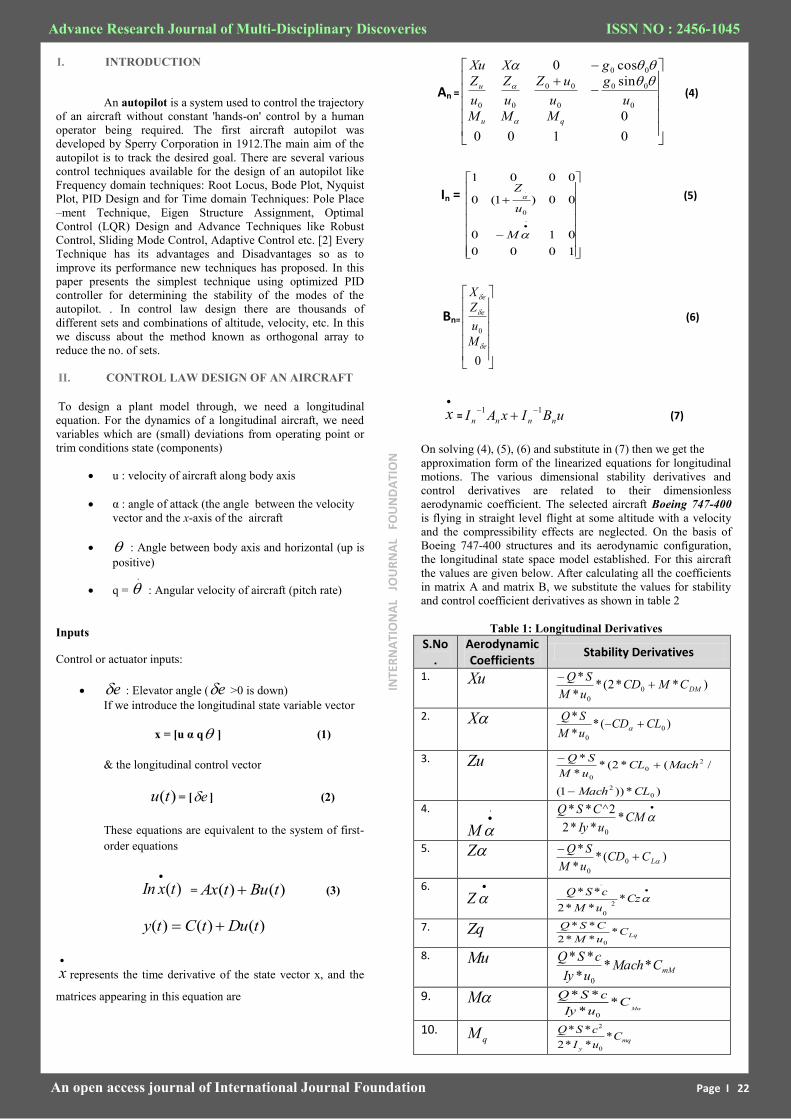
An =
0100
0
sin
cos0
0
00
0
00
00
00
qu
u
MMM
u
g
u
uZ
u
Z
u
Z
gXXu
(4)
In =
1000
010
00)1(0
0001
.0
.
M
u
Z (5)
Bn=
0
0
e
e
e
M
u
Z
X
(6)
x = uBIxAI nnnn
11 (7)
On solving (4), (5), (6) and substitute in (7) then we get the
approximation form of the linearized equations for longitudinal
motions. The various dimensional stability derivatives and
control derivatives are related to their dimensionless
aerodynamic coefficient. The selected aircraft Boeing 747-400
is flying in straight level flight at some altitude with a velocity
and the compressibility effects are neglected. On the basis of
Boeing 747-400 structures and its aerodynamic configuration,
the longitudinal state space model established. For this aircraft
the values are given below. After calculating all the coefficients
in matrix A and matrix B, we substitute the values for stability
and control coefficient derivatives as shown in table 2
Table 1: Longitudinal Derivatives
S.No.
Aerodynamic Coefficients
Stability Derivatives
1. Xu )**2(**
*0
0
DMCMCDuM
SQ
2. X )(**
*0
0
CLCDuM
SQ
3. Zu
)*))1(
/(*2(**
*
0
2
2
0
0
CLMach
MachCLuM
SQ
4. .
M
CMuIy
CSQ*
**2
2^**
0
5. Z )(**
*0
0
LCCDuM
SQ
6.
Z
CzuM
cSQ*
**2
**2
0
.
7. Zq LqC
uM
CSQ*
**2
**
0
8. Mu mMCMach
uIy
cSQ**
*
**
0
9. M M
CuIy
cSQ*
*
**
0
10. qM
mq
y
CuI
cSQ*
**2
**
0
2
INTE
RN
ATI
ON
AL
JO
UR
NA
L F
OU
ND
ATI
ON
Advance Research Journal of Multi-Disciplinary Discoveries ISSN NO : 2456-1045
When the aircraft is in status (H=300000Kg, Mach=0.35,
Velocity=114.97m/s, Altitude= 7000m).The altitude (Height)
and velocity will be varying but all the coefficient derivatives
will remain constant.
A. Modes of typical aircraft
The natural response of most aircraft to longitudinal
perturbations typically consists of two under- damped oscillatory
modes having rather different time scales. One of the modes has
a relatively short period and is usually quite heavily damped; this
is called the short period mode. The other mode has a much
longer period and is rather lightly damped; this is called the
phugoid mode.
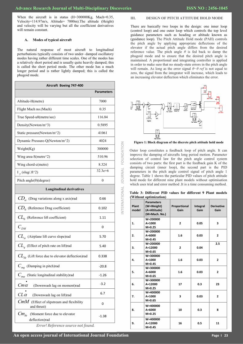
Aircraft Boeing 747-400
Parameters
Altitude-H(metre) 7000
Flight Mach no.(Mach) 0.35
True Speed-u0(metre/sec) 116.84
Density(Newton/m^3) 0.5895
Static pressure(Newton/m^2) 41061
Dynamic Pressure-Q(Newton/m^2) 4024
Weight(Kg) 300000
Wing area-S(metre^2) 510.96
Wing chord-c(metre) 8.324
I y (slug/.ft^2) 32.3e+6
Pitch angle(θ)(degree) 0
Longitudinal derivatives
CD (Drag variations along x axis)rad 0.66
0CD (Reference Drag coefficient) 0.102
0CL (Reference lift coefficient) 1.11
DMC 0
CL (Airplane lift curve slope)rad 5.70
qCL (Effect of pitch rate on lift)rad 5.40
eCL (Lift force due to elevator deflection)rad 0.338
mqC (Damping in pitch)rad -20.8
mC (Static longitudinal stability)rad -1.26
Cm (Downwash lag on moment)rad -3.2
CL (Downwash lag on lift)rad 6.7
CmM (Effect of slipstream and flexibility
and thrust) 0
eCm (Moment force due to elevator
deflection)rad -1.38
Error! Reference source not found.
An open access journal of International Journal Foundation Page I 23
III. DESIGN OF PITCH ATTITUDE HOLD MODE
There are basically two loops in the design: one inner loop
(control loop) and one outer loop which controls the top level
guidance parameters such as heading or altitude known as
(guidance loop). The Pitch Attitude Hold mode (PAH) controls
the pitch angle by applying appropriate deflections of the
elevator if the actual pitch angle differs from the desired
reference value. The pitch angle θ is fed back to damp the
phugoid mode and to ensure that the desired pitch angle is
maintained. A proportional and integrating controller is applied
in order to make sure that no steady-state errors in the pitch angle
will remain. As long as the error signal θ−θ ref is not equal to
zero, the signal from the integrator will increase, which leads to
an increasing elevator deflection which eliminates the error.
Figure 1: Block diagram of the discrete pitch attitude hold mode
Outer loop constitutes a feedback loop of pitch angle. It can
improve the damping of aircrafts long period motion. Parameter
selection of control law for the pitch angle control system
consists of two parts: the first part is the feedback gain K of the
damping circuit (inner loop), the second part is the PID
parameters in the pitch angle control signal of pitch angle 1
degree. Table 1 shows the particular PID values of pitch attitude
hold mode for different nine plant models without optimisation
which uses trial and error method .It is a time consuming method.
Table 3: Different PID values for different 9 Plant models
(Without optimization)
Plant model
Parameters (W=Weight) (A=Altitude) (M=Mach. No.)
Proportional Gain
Integral Gain
Derivative Gain
1. W=200000 A=1000 M=0.25
2 0.05 3
2. W=200000 A=6000 M=0.45
1.6 0.03 2
3. W=200000 A=12000 M=0.65
2 0.04 2.5
4. W=300000 A=1000 M=0.45
1.6 0.03 2
5. W=300000 A=6000 M=0.65
1.6 0.03 2
6. W=300000 A=12000 M=0.25
17 0.3 23
7. W=400000 A=1000 M=0.65
3 0.03 2
8. W=400000 A=6000 M=0.25
10 0.3 8
9. W=400000 A=12000 M=0.45
16 0.5 11
INTE
RN
ATI
ON
AL
JO
UR
NA
L F
OU
ND
ATI
ON
Advance Research Journal of Multi-Disciplinary Discoveries ISSN NO : 2456-1045
An open access journal of International Journal Foundation Page I 24
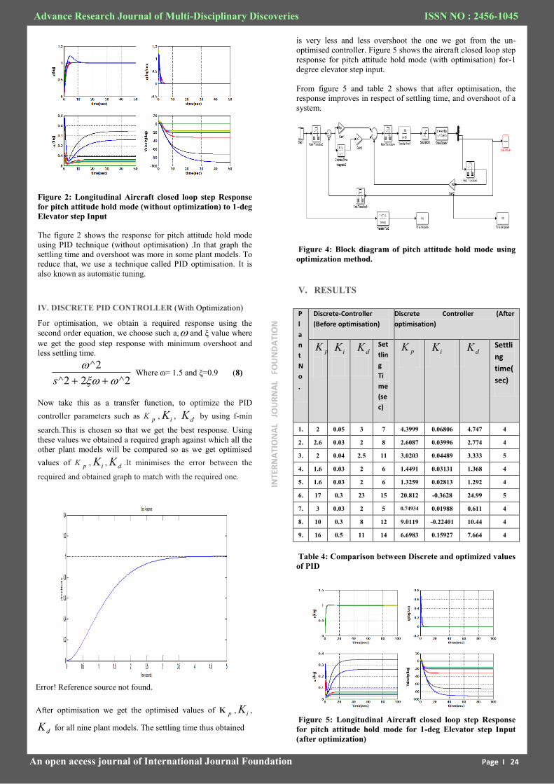
Figure 2: Longitudinal Aircraft closed loop step Response
for pitch attitude hold mode (without optimization) to 1-deg
Elevator step Input
The figure 2 shows the response for pitch attitude hold mode
using PID technique (without optimisation) .In that graph the
settling time and overshoot was more in some plant models. To
reduce that, we use a technique called PID optimisation. It is
also known as automatic tuning.
IV. DISCRETE PID CONTROLLER (With Optimization)
For optimisation, we obtain a required response using the
second order equation, we choose such a, and ξ value where
we get the good step response with minimum overshoot and
less settling time.
2^22^
2^
s Where ɷ= 1.5 and ξ=0.9 (8)
Now take this as a transfer function, to optimize the PID
controller parameters such as K p , iK , dK by using f-min
search.This is chosen so that we get the best response. Using
these values we obtained a required graph against which all the
other plant models will be compared so as we get optimised
values of K p , iK , dK .It minimises the error between the
required and obtained graph to match with the required one.
Error! Reference source not found.
After optimisation we get the optimised values of K p , iK ,
dK for all nine plant models. The settling time thus obtained
is very less and less overshoot the one we got from the un-
optimised controller. Figure 5 shows the aircraft closed loop step
response for pitch attitude hold mode (with optimisation) for-1
degree elevator step input.
From figure 5 and table 2 shows that after optimisation, the
response improves in respect of settling time, and overshoot of a
system.
Figure 4: Block diagram of pitch attitude hold mode using
optimization method.
V. RESULTS
P
l
a
n
t
N
o
.
Discrete-Controller
(Before optimisation)
Discrete Controller (After
optimisation)
pK
iK
dK
Set
tlin
g
Ti
me
(se
c)
pK iK
dK
Settli
ng
time(
sec)
1. 2 0.05 3 7 4.3999 0.06806 4.747 4
2. 2.6 0.03 2 8 2.6087 0.03996 2.774 4
3. 2 0.04 2.5 11 3.0203 0.04489 3.333 5
4. 1.6 0.03 2 6 1.4491 0.03131 1.368 4
5. 1.6 0.03 2 6 1.3259 0.02813 1.292 4
6. 17 0.3 23 15 20.812 -0.3628 24.99 5
7. 3 0.03 2 5 0.74934 0.01988 0.611 4
8. 10 0.3 8 12 9.0119 -0.22401 10.44 4
9. 16 0.5 11 14 6.6983 0.15927 7.664 4
Table 4: Comparison between Discrete and optimized values
of PID
Figure 5: Longitudinal Aircraft closed loop step Response
for pitch attitude hold mode for 1-deg Elevator step Input
(after optimization)
INTE
RN
ATI
ON
AL
JO
UR
NA
L F
OU
ND
ATI
ON
Advance Research Journal of Multi-Disciplinary Discoveries ISSN NO : 2456-1045
An open access journal of International Journal Foundation Page I 25
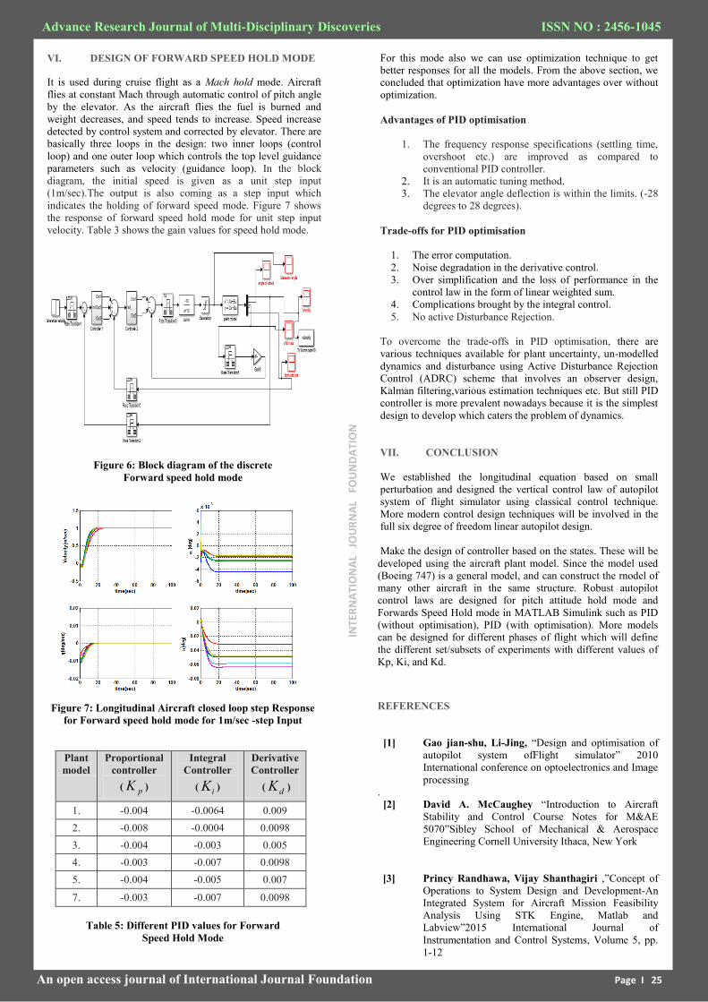
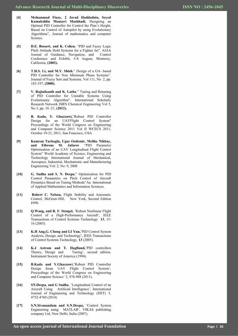
VI. DESIGN OF FORWARD SPEED HOLD MODE
It is used during cruise flight as a Mach hold mode. Aircraft
flies at constant Mach through automatic control of pitch angle
by the elevator. As the aircraft flies the fuel is burned and
weight decreases, and speed tends to increase. Speed increase
detected by control system and corrected by elevator. There are
basically three loops in the design: two inner loops (control
loop) and one outer loop which controls the top level guidance
parameters such as velocity (guidance loop). In the block
diagram, the initial speed is given as a unit step input
(1m/sec).The output is also coming as a step input which
indicates the holding of forward speed mode. Figure 7 shows
the response of forward speed hold mode for unit step input
velocity. Table 3 shows the gain values for speed hold mode.
Figure 6: Block diagram of the discrete
Forward speed hold mode
Figure 7: Longitudinal Aircraft closed loop step Response
for Forward speed hold mode for 1m/sec -step Input
Plant
model
Proportional
controller
( pK )
Integral
Controller
( iK )
Derivative
Controller
( dK )
1. -0.004 -0.0064 0.009
2. -0.008 -0.0004 0.0098
3. -0.004 -0.003 0.005
4. -0.003 -0.007 0.0098
5. -0.004 -0.005 0.007
7. -0.003 -0.007 0.0098
Table 5: Different PID values for Forward
Speed Hold Mode
For this mode also we can use optimization technique to get
better responses for all the models. From the above section, we
concluded that optimization have more advantages over without
optimization.
Advantages of PID optimisation
1. The frequency response specifications (settling time,
overshoot etc.) are improved as compared to
conventional PID controller.
2. It is an automatic tuning method.
3. The elevator angle deflection is within the limits. (-28
degrees to 28 degrees).
Trade-offs for PID optimisation
1. The error computation.
2. Noise degradation in the derivative control.
3. Over simplification and the loss of performance in the
control law in the form of linear weighted sum.
4. Complications brought by the integral control.
5. No active Disturbance Rejection.
To overcome the trade-offs in PID optimisation, there are
various techniques available for plant uncertainty, un-modelled
dynamics and disturbance using Active Disturbance Rejection
Control (ADRC) scheme that involves an observer design,
Kalman filtering,various estimation techniques etc. But still PID
controller is more prevalent nowadays because it is the simplest
design to develop which caters the problem of dynamics.
VII. CONCLUSION
We established the longitudinal equation based on small
perturbation and designed the vertical control law of autopilot
system of flight simulator using classical control technique.
More modern control design techniques will be involved in the
full six degree of freedom linear autopilot design.
Make the design of controller based on the states. These will be
developed using the aircraft plant model. Since the model used
(Boeing 747) is a general model, and can construct the rnodel of
many other aircraft in the same structure. Robust autopilot
control laws are designed for pitch attitude hold mode and
Forwards Speed Hold mode in MATLAB Simulink such as PID
(without optimisation), PID (with optimisation). More models
can be designed for different phases of flight which will define
the different set/subsets of experiments with different values of
Kp, Ki, and Kd.
REFERENCES
[1] Gao jian-shu, Li-Jing, “Design and optimisation of
autopilot system ofFlight simulator” 2010
International conference on optoelectronics and Image
processing
.
[2] David A. McCaughey “Introduction to Aircraft
Stability and Control Course Notes for M&AE
5070”Sibley School of Mechanical & Aerospace
Engineering Cornell University Ithaca, New York
[3] Princy Randhawa, Vijay Shanthagiri ,”Concept of
Operations to System Design and Development-An
Integrated System for Aircraft Mission Feasibility
Analysis Using STK Engine, Matlab and
Labview”2015 International Journal of
Instrumentation and Control Systems, Volume 5, pp.
1-12
INTE
RN
ATI
ON
AL
JO
UR
NA
L F
OU
ND
ATI
ON
Advance Research Journal of Multi-Disciplinary Discoveries ISSN NO : 2456-1045
An open access journal of International Journal Foundation Page I 26
[4] Mohammad Fiuzy, 2 Javad Haddadnia, Seyed
Kamaleddin Mousavi Mashhadi, Designing an
Optimal PID Controller for Control the Plan’s Height,
Based on Control of Autopilot by using Evolutionary
Algorithms”, Journal of mathematics and computer
Science.
[5] D.E. Bossert, and K. Cohen. “PID and Fuzzy Logic Pitch Attitude Hold Systems for a Fighter Jet”. AIAA
Journal of Guidance, Navigation, and Control
Conference and Exhibit, 5-8 August, Monterey,
California, (2002).
[6] T.H.S. Li, and M.Y. Shieh.” Design of a GA- based
PID Controller for Non Minimum Phase Systems”.
Journal of Fuzzy Sets and Systems, Vol 111, No 2, pp.
183-197, (2000).
[7] V. Rajinikanth and K. Latha.” Tuning and Retuning
of PID Controller for Unstable Systems Using
Evolutionary Algorithm”. International Scholarly
Research Network ISRN Chemical Engineering Vol 5,
No 3, pp. 10 -21, (2012).
[8] B. Kada, Y. Ghazzawi,”Robust PID Controller
Design for an UAVFlight Control System" Proceedings of the World Congress on Engineering
and Computer Science 2011 Vol II WCECS 2011,
October 19-21, 2011, San Francisco, USA
[9] Kamran Turkoglu, Ugur Ozdemir, Melike Nikbay,
and Elbrous M. Jafarov “PID Parameter
Optimization of an UAV Longitudinal Flight Control
System” World Academy of Science, Engineering and
Technology International Journal of Mechanical,
Aerospace, Industrial, Mechatronic and Manufacturing
Engineering Vol: 2, No: 9, 2008
[10] G. Sudha and S. N. Deepa,” Optimization for PID
Control Parameters on Pitch Control of Aircraft
Dynamics Based on Tuning Methods”An International
of Applied Mathematics and Information Sciences.
[11] Robert C. Nelson, Flight Stability and Automatic
Control, McGraw-Hill, New York, Second Edition
1998.
[12] Q.Wang, and R. F. Stengel, ’Robust Nonlinear Flight
Control of a High-Performance Aircraft’, IEEE
Transactions of Control Systems Technology 13, 15-
16 (2005).
[13] K.H Ang,G. Chong and LI Yun,’PID Control System
Analysis, Design, and Technology’, IEEE Transactions
of Control Systems Technology, 13 (2005).
[14] K.J Astrom and T. Hagllund,’PID controllers
Theory, Design and Tuning’, second edition,
Instrument Society of America (1994).
[15] B.Kada and Y.Ghazzawi,’Robust PID Controller
Design foran UAV Flight Control System’,
Proceedings of the World Congress on Engineering
and Computer Science’ 2, 978-988 (2011).
[16] SN.Deepa, and G Sudha, ’Longitudinal Control of an
Aircraft Using Artificial Intelligence’, International
Journal of Engineering and Technology (IJET) 5,
4752-4760 (2014)
[17] S.N.Sivanandam and S.N.Deepa, ’Control System
Engineering using MATLAB’, VIKAS publishing
company Ltd, New Delhi, India (2007).


![The relation between the 3-D bode diagram and the root ...dcsl.gatech.edu/papers/3DBodePlot.pdfthe Nyquist plot [3], these techniques form the major part of what is commonly known](https://img.pdfslide.us/doc/110x75/5e789fe7523c911a1d69a0b2/the-relation-between-the-3-d-bode-diagram-and-the-root-dcsl-the-nyquist-plot.jpg)