Embed Size (px)
Citation preview
Accepted Manuscript
Outlook of carbon capture technology and challenges
Tabbi Wilberforce, A. Baroutaji, Bassel Soudan, Abdul Hai Al-Alami, Abdul Ghani Olabi
PII: S0048-9697(18)34779-XDOI: https://doi.org/10.1016/j.scitotenv.2018.11.424Reference: STOTEN 29773
To appear in: Science of the Total Environment
Received date: 10 October 2018Revised date: 28 November 2018Accepted date: 28 November 2018
Please cite this article as: Tabbi Wilberforce, A. Baroutaji, Bassel Soudan, Abdul Hai Al-Alami, Abdul Ghani Olabi , Outlook of carbon capture technology and challenges. Stoten(2018), https://doi.org/10.1016/j.scitotenv.2018.11.424
This is a PDF file of an unedited manuscript that has been accepted for publication. Asa service to our customers we are providing this early version of the manuscript. Themanuscript will undergo copyediting, typesetting, and review of the resulting proof beforeit is published in its final form. Please note that during the production process errors maybe discovered which could affect the content, and all legal disclaimers that apply to thejournal pertain.
ACCEP
TED M
ANUSC
RIPT
1
Outlook of Carbon Capture Technology and Challenges
Tabbi Wilberforce1, A. Baroutaji
2*, Bassel Soudan3, Abdul Hai Al-Alami3, Abdul Ghani Olabi
3,4
1. Institute of Engineering and Energy Technologies, University of the West of Scotland, UK
2. School of Engineering, Faculty of Science and Engineering, University of Wolverhampton, UK
3. Dept. of Sustainable and Renewable Energy Engineering, University of Sharjah, P.O. Box 27272,
Sharjah, UAE
4. School of Engineering and Applied Science, Aston University, Aston Triangle, Birmingham B4 7ET,
UK
Abstract
The greenhouse gases emissions produced by industry and power plants are the cause of climate
change. An effective approach for limiting the impact of such emissions is adopting modern
Carbon Capture and Storage (CCS) technology that can capture more than 90% of carbon
dioxide (CO2) generated from power plants.
This paper presents an evaluation of state-of-the-art technologies used in the capturing CO2. The
main capturing strategies including post-combustion, pre-combustion, and oxy – combustion are
reviewed and compared. Various challenges associated with storing and transporting the CO2
from one location to the other are also presented. Furthermore, recent advancements of CCS
technology are discussed to highlight the latest progress made by the research community in
developing affordable carbon capture and storage systems. Finally, the future prospects and
sustainability aspects of CCS technology as well as policies developed by different countries
concerning such technology are presented.
Keywords: Carbon dioxide, Absorption, gasification, membrane, Storage
ACCEPTED MANUSCRIPT
ACCEP
TED M
ANUSC
RIPT
2
1. Introduction
Global warming is a major issue for most research centers and governmental institutions around
the world [1 – 5]. It occurs due to high amounts of CO2 in the airspace. Currently, most countries
around the world still rely heavily on fossil commodities, which release significant amounts of
CO2, for power generation where almost 85% of power generated across the globe is from fossil
fuel [6 – 9]. A drastic substitution of the traditional power plant with alternative clean energy
generation mediums, which produce no CO2, is virtually impossible in the near future. Therefore
CCS technology has received increased awareness by research community. CCS technology
helps in reducing carbon dioxide in the atmosphere that lead to depletion of the ozone layer and
climate change [10]. It is expected that the next few years will see CCS as one of the cheapest
methods for minimizing greenhouse gases [11, 12]. Main steps for implementing CCS in any
power plant are presented in Fig. 1.
The CCS process starts with capturing the carbon dioxide generated by the biomass or fossil
commodities. The carbon dioxide then undergoes a compression process to form a dense fluid.
This helps in transporting the CO2 as well as storing it. Dense fluid is transported via pipelines
and then injected in an underground storage facility.
The current CCS technologies are generally very expensive and significant developments are
needed to develop a more affordable CCS technology. Thus, the main objective for this
investigation is to review CCS technologies and to explore the recent efforts made by the
scientific community to come out with a new approach that can reduce the overall cost of this
vital technology [13].
ACCEPTED MANUSCRIPT
ACCEP
TED M
ANUSC
RIPT
3
2. CO2 capturing technologies
Significant amounts of CO2 are produced during the combustion of natural gas. This amount of
CO2 is either directed towards the atmosphere or used in manufacturing plants to produce other
commodities as in food processing industry [14]. However, small quantity of the generated
carbon dioxide is reused by manufacturing industry as well as most of the carbon dioxide
eventually ends up in the atmosphere [15].
Several strategies for capturing carbon dioxide from gaseous mixtures have been designed and
utilized in the industry. Fig. 2 depicts the recent technologies used for capturing carbon dioxide.
The type of technology is determined by the purity and state of the gas in relation ambient
conditions surrounding the CO2 [16]. Carbon dioxide capturing systems help in elimination of
pollutants from the carbon dioxide during natural gas refining process as well as the generation
of H, NH3 and other chemicals for industrial purposes.
Overall aim for all carbon capture and storage technologies is to generate carbon dioxide that can
be stored in a geological formation. To materialize this, carbon dioxide must be compressed to a
liquid state in order to be transported easily through pipelines and eventually pumped into a
geological formation. The carbon compression stage can thus be defined as part of the CCS
system [17, 18]. Today, the technologies utilized for CCS are grouped as pre – combustion or
post – combustion systems. These technologies are named depending on the timing when the
carbon is eliminated that is prior or after the fossil fuel combustion [16]. There is another CCS
technology, known as the oxyfuel or oxy – combustion, which is still under developmental stages
and it requires sometime before it becomes commercially acceptable. The technology used by
power plants is similar to that used by some industrial activities devoid of burning.
ACCEPTED MANUSCRIPT
ACCEP
TED M
ANUSC
RIPT
4
2.1 CO2 Separation techniques for CCS
2.1.1 Physical absorption
There are two main stages with the physical absorption process. These are the absorption and
stripping process. The absorption process involves treated gas being in contact with solvent
stream and the CO2 being captured by the solvent physically. The stripping involves CO2 and
solvent which is normally saturated is introduced to heat to produce new solvent and releasing
the CO2 at the apex of the stripping Chamber. Extent of CO2 absorption for solvent is built
around Henry’s law. Dissolution of CO2 in the liquefied solvent is due to electrostatic forces.
Low temperature as well as high pressure are the best operating conditions for Physical
absorption. Other conditions like high temperature but low pressure affects physical desorption.
Physical absorption has good absorption characteristics compared to chemical absorbent [19,20].
Its regeneration can be achieved via depressurization operation at lpw energy demand. This is the
main reason for their dominance in pre-combustion carbon capture technology. They are useful
in IGCC power plants elimination of carbon dioxide from synthesis gas, natural gas treatment as
well as acid gas recovery as well. It must be noted that the capacity for absorption absorbent is
useful at lower temperatures physically. It implies that reducing the temperatures of treated gas
streams before absorption is very important [21]. The well-known physical absorption process
involves Selexol, Rectisol, Purisol and Fluor method.
2.1.2 Adsorption
Adsorption is slightly different from absorption because adsorption includes specific creation of
physical and chemical connection between CO2 and surface of the adsorbent. The adsorbed CO2
then disappear via pressure swing adsorption (PSA) or temperature swing adsorption (TSA)) in
order to regenerate the adsorbent material. The adsorbent which is saturated is heated in
Temperature swing adsorption to operating conditions at which physical and chemical bond is
ACCEPTED MANUSCRIPT
ACCEP
TED M
ANUSC
RIPT
5
disintegrated leading to the detachment of adsorbed reactants but for pressure swing adsorption
there is reduction of pressure to generate the same effect. When the CO2 concentration is
insignificant, temperature swing adsorption is often used but when the CO2 concentration is high
PSA is preferred [22, 23]. Pressure swing adsorption is useful because of its short temporal need
for regenerating the adsorbent. Some well-known physical adsorbent are zeolite and amine
sorbents
2.1.3 Membrane Technology
Knudsen diffusion principle is the phenomenon that leads to membrane separation. CO2
dissolves in the membrane and diffuse via rate proportional to its partial pressure gradient.
Utilization of non-facilitated membrane technology is predominant in CO2 elimination from
natural gas and where the carbon dioxide partial pressure is high. In capturing carbon from flue
gas because the carbon dioxide is less, there would be more energy imposed because
compression work is need to support enough driving force to obtain the required carbon capture
ratio. Enhancement of its selectivity is dependent on how permeable the membrane is designed
to be. It implies that even though it has many merits like low environmental effect and
degradation, integrating it to power plant already in existence poses a challenge. Researchers
today are investigating on many ways of averting this challenge. The facilitated transport
membrane separation is one of the newly designed approach recommended by researchers
around the world. It is made up of mobile or liquid phase carrier that support movement of CO2
as bicarbonate. This will support the permeability as well as the selectivity of CO2 across the
membrane. The mixed matrix membrane is also new type of membrane technology [24 – 26].
They are made up of polymer membranes fillers. Some of the fillers are; zeolite, mesoporous
silica and zeolitic imidazolate. These modified membranes reduce the processing cost and
increase permeability. The strength and stability with respect to heat for these membranes are
ACCEPTED MANUSCRIPT
ACCEP
TED M
ANUSC
RIPT
6
very good. Other new type of membrane separation technology is the gas membrane contactor.
These types of membranes are not dependent on the Knudsen diffusion approach. The
membranes for the gas membrane contactor only act as a point of application between the flu gas
as well as CO2 absorption solvent. They show compactness of the membrane system and high
selectivity of amine-based absorption process. Their main demerits are that there are limitations
in terms of mass transport because of resistance on the membrane framework.
2.1.4 Cryogenic Separation
This approach involves several compression applications at ambient temperature as well as
pressure for separating the gas. This technique is suitable for producing liquid carbon dioxide
[26]. It is ideal for carbon dioxide capture in high concentrations. This technology can also be
used in place of amine-based scrubbing method because it utilizes water in lesser quantity, uses
cheap chemical agents, corrosion resistant and less effect on the environment in terms of
pollution. This concept also supports ambient pressure operation as well as liquid CO2. They
therefore support CO2 transmission economically. Cryogenic separation has some limitations too
[27]. It is energy intensive due to the operating temperature range being low hence high cost of
operation. Formation of ice in cryogenic approach often causes the piping system being blocked
and this reduces the drop-in pressure causing safety issues. It therefore becomes important that
the amount of moisture is removed before the separation process. This process adds to the initial
cost of using this technology.
2.2 Pre – combustion approach
This technology employs the separation of carbon dioxide from fossil commodities prior to
burning process being started [28]. This technology can further be explained as a reacting fuel
and O2 gas to generate carbon monoxide, hydrogen as well as fuel gas. A pure hydrogen fuel
stream is obtained after the removal of carbon dioxide [29]. By means of integrated gasification,
ACCEPTED MANUSCRIPT
ACCEP
TED M
ANUSC
RIPT
7
carbon dioxide can be obtained. The technology is also applicable to power plants that uses
natural gas [30,31]. Fig. 3 shows a diagram of carbon dioxide capture using the pre combustion
technology approach. Table 1 also capture recent studies conducted in this field.
The first major step conducted during the elimination of carbon from fuel is to change the fuel to
a form that is quite easy to capture. A reaction between coal with steam and oxygen gas is the
usual phenomenon for power plants fueled by coal and the reaction occurs at higher temperature
as well as pressure [30]. End product of this reaction is a fuel made up of CO as well as mixture
of hydrogen called syngas. This gas can further go through a combustion process to produce
power in power plant. The power generated is often referred to as Integrated Gasification
Combined Cycle (IGCC) power. In second step of this process, the carbon monoxide obtained in
first step is transformed into carbon dioxide via a reaction with steam. This leads to the
formation of carbon dioxide and hydrogen.
A glycol solvent, known as Selexol, is used to trap the carbon dioxide through a chemical
process. This results in purified hydrogen gas which goes through another plant to produce
power shown in Fig. 3(a). Easy and cheaper separation of carbon dioxide due to the operating
pressure being high as well as excellent concentrations of carbon dioxide using IGCC plants
makes them the mostly preferred option by the research community even though they are very
expensive compared to the traditional coal combustion plants. The operational approach for pre-
combustion includes absorption physically, then releasing the CO2 once the sorbent pressure
drops, as depicted in Fig. 3(b), instead of using a chemical approach to trap the carbon dioxide
like using amine systems in post combustion capture. The use of IGCC involves some limitations
as there are some loss in energy during the carbon dioxide capture because of the shift reactor
and other steps involves in this process.
ACCEPTED MANUSCRIPT
ACCEP
TED M
ANUSC
RIPT
8
It is also possible to use pre – combustion carbon dioxide capture in power plants that utilizes
natural gas. Using natural gas as fuel involves conversion of the gaseous fuel to synthesis gas
through reactions with O2 often referred to as reforming. Concentrated carbon dioxide and
hydrogen is produced [19 - 35]. It must be noted that this method is very expensive compared to
using natural gas as fuel but in post combustion capture approach.
2.3 Post- combustion approach
The post combustion carbon capture (PCC) absorbs the carbon dioxide produced by the flue
miasma after fossil commodities or materials made of carbons undergo a combustion process.
The greatest quantity of electricity used by the world in recent times is obtained from power
plants that functions through a combustion process. The main process in coalfired power plants
used today is the burning of coal fused with air in a boiler or a furnace [36]. The process is an
exothermic reaction and the steam released is used to run a turbine generator shown in Fig. 4.
The high temperature gases that flows out of the boiler is made up of nitrogen from air and water
vapor in smaller concentrations. There is also carbon dioxide produced from the hydrogen and
carbon from the fuel used. Sulfide dioxide (SO2), nitrogen oxide (NO) and fly ash (particulate
matter) are also formed due to the burning of impurities in coal. These toxic gases and others like
mercury must be eliminated as they are considered as pollutants according to emission standards
[37]. In some situations, elimination of pollutants like SO2 helps in the provision of pure gas
stream for capturing CO2 [37]. Chemical reaction is described by scientists as the outstanding
option for capturing CO2 from flu gases of a pulverized coal plant but a solvent called
monoethanolamine (MEA) is also required to facilitate the chemical reaction process. MEA is a
member of the amine compound. The flue gas is first scrubbed in a vessel called an absorber.
The absorber helps in the capturing around 85% to 90% of the CO2 produced. CO2 in a form of a
solvent is injected into another vessel named as the regenerator or the stripper. In the second
ACCEPTED MANUSCRIPT
ACCEP
TED M
ANUSC
RIPT
9
vessel, the release of CO2 involves usage of steam. The CO2 produced after this process is highly
concentrated [38]. The gas is compressed as well as conveyed to a location where they can be
stored. The solvent used in the process is the forced back and recycled to the absorber. A detailed
post combustion capturing of carbon dioxide is shown in Fig. 5 [39].
This technological approach is suitable for capturing carbon dioxide at pulverized coal power
plant as well as at a natural gas fired boiler. Fig. 6 explains this methodology. The coal plants
often have the flue gas carbon dioxide concentration being denser compared to the natural gas
combined cycle, NGCC, but it is still possible to obtain high removal efficiencies even with the
amine based capture systems [40]. The natural gas has no impurities hence the flue gas stream is
very clean. This implies that there will be no need for any cleanup for capturing the CO2
effectively [41, 42]. Table 2 captures the recent studies for post combustion in carbon dioxide
capture.
2.4 Oxy – combustion approach
An option to post–combustion process, the oxy–combustion method has recently been developed
as CO2 capturing technology. This process uses pure oxygen in the combustion process and this
reduces the quantities of nitrogen [43 – 45]. Fly ash is also eliminated from flue gas stream
resulting in the flue gas which only made up of CO2 and water droplets as well as some
impurities like sulfur dioxide. Compression and reducing the temperature of the flue gas is a
medium used in the removal of the water vapor [46]. This process leaves behind pure carbon
dioxide which is storage directly as shown in Fig. 7. One advantage of oxy – combustion over
post combustion is the avoidance of an expensive CO2 capture system for post combustion [47 –
48]. In place of a CO2 capture systems for post combustion, the oxy combustion uses air
separation unit (ASU) to produce clean oxygen with around 95% to 99% purity for oxyfuel
systems compared to Integrated Gasification Combined Cycle plant of the same volume [49]. Air
ACCEPTED MANUSCRIPT
ACCEP
TED M
ANUSC
RIPT
10
separation unit affects the cost significantly. Extra gas transformation is often required to limit
the air pollutant concentration in order to meet the correct environmental guideline. This will
further reduce a build of unwanted materials in the flue gas recycle [49 – 54].
Temperature for burning using pure oxygen is greater than air hence oxy combustion involves
huge portion of the stream for the flue gas being used back in the boiler to maintain optimal
operating temperature. Recent oxy fueled boilers come in designs to reduce recycle using
slagging combustors or non – stoichiometric burners. Sealing of the system is another important
stage in the design to maintain the needed oxygen and nitrogen found in the gas. Sealing
prevents air leakages into the flue gas. This is considered as one of the most difficult
maintenance issues because the leakages at the flanges and joints are difficult to prevent
especially along the flue gas duct [55]. There has been several research work conducted on
30MW thermal plant that uses the oxy combustion technology. Oxyfuel systems requires gas
treatments to eliminate pollutants from the system and this reduces the efficiency of the system
to 90%. It is possible to apply the concept of oxy combustion in a simple cycle. Table 3 also
shows some current research conducted using the oxy combustion technology. Fig. 8 shows the
CCS technology as well as sources from different commodities like cement, steel production and
bioethanol plants. The bioethanol plants produce food grade carbon dioxide from fermenters.
This investigation explores the main technological advancement made in recent times with
respect to carbon capture [56]. Table 4 shows some recent advancement made in this technology.
2.5 Comparison of the various carbon capture capacity between 2006 - 2018
Carbon capture and storage involves large sequestration of CO2 from well-known origins
followed by separation from the atmosphere as well as its usage in futuristic terms. It is a
solution designed for a situation where high emissions of carbon dioxide due to high energy
consumption and high dependency on fossil commodities becomes unavoidable. It is a suitable
ACCEPTED MANUSCRIPT
ACCEP
TED M
ANUSC
RIPT
11
approach for carbon separation from high CO2 plants. Well known areas where carbon capture
and storage can be utilized are generation plants and manufacturing divisions. From Fig. 9, the
carbon emissions is likely to exceed 32.27 billion tonnes by 2018. Researchers anticipates that
by the year 2020, this quantity of CO2 emissions is likely to increase appreciably to 35.63 billion
as well as 43.22 billion by 2040. This increase according to researchers will emanate largely
from developing countries. 33.4 million tonnes of CO2 can be captured annually in spite of all the
carbon capture and storage facilities across the world. This is 0.09% of the total projected carbon
emissions. To combat climate change, expansion of CCS technology will be a necessity.
From Fig. 9, it is observed that between the year 2006 to 2018, the number of commercial carbon
capture facility for post combustion has surged up from from 16 to 30. This indicates a high
increase compared to pre combustion. It therefore explains the increase in carbon capture
capacity from 26000 Tonnes per day in 2006 to 50,000 tonnes per day in 2018. Pre – combustion
was nearly zero between 2006 to 2014 but after 2014, the capacity has increased to nearly 7000
tonnes per day in 2018. Table 5 also captures other technology for carbon capture but with
insufficient large scale experience.
Table 6 captures comparison between the three main CCS technologies; post combustion, pre-
combustion and oxyfuel combustion. Fig. 9 explains projected values for commercialized CCS
across the world. From Table 6, it is observed that oxyfuel combustion capture system presently
has no carbon capture storage. Most established CCS technology is the post combustion
technology. Researchers are also investigating on solid sorbent technologies in order to improve
their performance. Pre-combustion technology is described as the best alternative to mitigate this
challenge. A clear comparison for all the three types of CCS technology is shown in Table 6.
ACCEPTED MANUSCRIPT
ACCEP
TED M
ANUSC
RIPT
12
2.6 Transportation and storage of captured CO2
The captured carbon dioxide always needs to be transported from the capturing site to the storage
site. The key consideration that should be taken during the transportation of carbon dioxide are
the compression of the gas to a supercritical state, pipeline corrosion and the effect of fluid
composition on the power that will be consumed [89 – 103]. This can be achieved by
recompressing the pipeline at distance beyond 150 km. Transporting the carbon dioxide using
pipelines in bulk reduces the overall cost of the carbon capture and storage system. This is
considered a matured technology in the carbon capture and storage system. For over 40 years,
this technology has been adopted in the transportation of 50 Mtpa carbon dioxide via 3600 miles
[104]. Sharing the transportation network is one method of reducing cost. An in depth knowledge
on the thermodynamic and transport characteristics of carbon dioxide mixtures is very necessary
when designing a carbon capture system. Majority of the overall cost for the transportation and
storage of the carbon dioxide in a carbon capture and storage system occurs at the compression
stage of the carbon dioxide stream. An attempt to capture carbon dioxide at higher pressure
reduces the compression power at downstream.
In the last few decades, several geological sites have been used for storing CO2 such as saline
aquifers, depleted basins and enhanced oil recovery [105]. There are some requirements for any
storage sites to be suitable for storing CO2. The formation of the site must be porous and
permeable for easy injection of huge volumes of carbon dioxide. Also, it must have rock caps for
the imprisonment of the carbon dioxide and prevention of any potential leaking. Storing carbon
dioxide in an abandoned oil field is also appropriate because most of these sites become
impermeable after holding oil and gas for several years. These reservoirs have some
disadvantage as well as they are often penetrated by other wells damaging the seal. Retaining the
ACCEPTED MANUSCRIPT
ACCEP
TED M
ANUSC
RIPT
13
carbon dioxide carbon dioxide is achieved through a trapping mechanism: a) stratigraphic and
structural (primary trapping occurs beneath seals of low seals of low permeability rocks,
dominant at early stage); b) residual (Using water capillary pressure, trapping is achieved via
rock pores c) Solubility (residual gas trapping) and d) mineralization (changing the pore – space
topology and connectivity). There is precipitation of carbonates at the last stage of the storing
process and this is likely to block the pathway for the fluid and there is also finally a loss of the
storage pore volume [105].
Other researchers investigated the direct relationship between injection and induced seismicity
for a long term and concluded that this storage process could lead to earth quakes but the leakage
of carbon dioxide is not a major challenge in terms of scaling up carbon capture and storage
systems. The cost for the injection is approximately 0.5 – 8 $/tCO2. A combination of enhanced
oil recovery with a storage system will reduce the overall cost.
3. Application of the various CCS technologies
For commercial and industrial power plants, post-combustion carbon dioxide capture is
considered the matured type of technology compared to the others. . Using solvent for the carbon
dioxide capture is very important in post-combustion in the capture of carbon dioxide. Today,
researchers are also exploring the various type of solvent, design and an integrated solvent
design for the capture of carbon dioxide. Other investigations into the selection systematically
and design of solvent for post-combustion carbon dioxide capture using several predictive
methods have all been explored [106,107]. Several computational and statistical strategies have
all been used during the investigation. For instance, the fluid theory family approach and
quantitative structure property relationship have all be utilized during the conduction of an
investigation [108,109]. Using universal quasi – chemical functional group activity coefficient
approach has been designed for the capture of carbon dioxide [110]. Other researchers attempted
ACCEPTED MANUSCRIPT
ACCEP
TED M
ANUSC
RIPT
14
the possibility of adding the solvent selection process with the carbon dioxide capture process
[111-118].
For renovation of existing power plants, post combustion carbon dioxide capture is considered
the best of options. This method has thoroughly been investigated as a medium of enhancing the
performance of any equipment. As explained earlier, several numerical studies and modelling
research work has been conducted using the approach [119]. Due to the gas volume being low,
pressure being high and the amount of carbon dioxide also being high, less energy is often
required for pre combustion carbon dioxide. Less amount of water consumption is observed for
pre-combustion compared to post-combustion. An alternative fuel generated for pre-combustion
is hydrogen/syngas [120]. The oxyfuel – combustion is considered more environmentally
friendly compared to the other two methods. There is no need for any operations being done
chemically for this types of carbon dioxide capture technology and also suitable for several types
of coal fuels [121-125]. It is simple to renovate it compared to the other types like the post-
combustion capture system. This approach has high efficiency in terms of carbon capture. Some
advantages of this type of carbon dioxide capture technology is the fact that the equipment size
is reduced, the air separation technology is high, it is well suited for conventional, efficient steam
cycle with less modifications and the removal of NOx control as well as the carbon dioxide
separation stage makes it very advantageous [126-132].
3.1 Capturing of carbon from exhaust gases
There is always a capturing energy penalty of 15% to 30% for power plants operated using
carbon and this contributes to almost –85% of the carbon capture and storage expenditure [133].
To develop a carbon fired plant with an efficiency of 33% involves decreasing the power output
by 1/3 and this increase the capital expenditure to approximately 77% [134]. Power plants fired
by carbon have varying carbon dioxide emissions because of the variation in the fuel used but
ACCEPTED MANUSCRIPT
ACCEP
TED M
ANUSC
RIPT
15
power plants fired by coal produces 1116 gCO2/KWh at 30% and 669 gCO2/kWh at 50%
efficiency [135]. Even though coal is considered carbon dioxide intensive option, expansion in
terms of capacity shows that initiatives for carbon mitigation are low compared to the economic
incentives for a relatively cheap fuel. In terms of capital expenditure, natural gas fired power
plant is better than power plants fired by coal since half of the capital expenditure for coal fired
power plant is required for natural gas powered plant [136]. The overall performance
uncertainties are estimated probabilistically [141]. Uncertainties with regards to the capital
expenditure are very high at an approximated value of 40% although variability has little
influence on the levelized cost of energy (LCOE) [137]. This shows that the operational costs
(OPEX) determines the overall cost of carbon capture and storage. Other investigators reported
that post combustion capture of carbon dioxide capture using chemical absorption is the most
effective and cheapest means of carbon capture and storage technique [138]. The main obstacle
is heat demand which increases the operational cost and this also reduces the power capacity.
Power plants fired by carbon via hybridization using solar aided post combustion improves the
overall efficiency of the plants. There is limitation in terms of the driving force for state of the art
membrane permeation compared to chemical absorption in the capture of carbon dioxide from
exhaust gases [139]. The reliance of fossil commodities when using coal fired plants can be
replaced using renewable energy and this will reduce the fossil commodity that will go into
combustion. The energy obtained from renewable energy being intermittent implies that the unit
for capturing the carbon must be flexible in order to enhance the economics of the carbon
capture. Flexibility is obtained by storing the solvent, removing energy generation from the
capture of carbon dioxide to meet energy prices at peak times [96]. The flexibility of capturing
unit helps in reducing the capital expenditure to 28% [140]. Capture energy penalty is reduced
due to variable capture aligned to energy demand and dispatch and this often leads to increasing
ACCEPTED MANUSCRIPT
ACCEP
TED M
ANUSC
RIPT
16
net efficiency and capacity [141]. A practical example is the absorber sized for a time average
condition cost approximately 4% less than when it is sized for peak energy generation [141].
3.2 Carbon dioxide capture from Natural Gas
Similar to post combustion, natural gas is also dominated by precisely physical absorption [142].
Natural gas processing for Floating Production Storage and Offloading (FPSO) is slightly
different from other natural gas processing. For natural gas processing of FPSOs, small area
creates a technology niche for membrane permeation because it has low foot print and
modularity. For instance the first PFSO started operation in 2010 for the Brazil pre sal oil and
gas field [142] and they used membrane separation for separating carbon dioxide. Seven PFSO
were being operated actively in 2016 [100] and six out of the seven were functioning via
membrane permeation with each processing approximately 4 – 7 MMscmd of natural gas with
almost 20% of carbon dioxide [143]. One of the key factors for the selection of natural gas
processing technology is the partial pressure of carbon dioxide in raw natural gas and plant
location. Chemical absorption is suitable for low carbon dioxide feed that is less than 20%
because higher carbon dioxide content increases solvent recirculation rate and heat duty.
Membrane permeation is best suited for medium to higher carbon dioxide partial pressure
compare to chemical absorption. Other high carbon dioxide content project could be found in pre
-salt field in Brazils’ offshore pre oil field (Libra: 48%, Jupiter 78%) and La Barge gas field in
Wyoming in the United States but these projects function using cryogenic distillation. The main
merit of these projects is the fact that the carbon dioxide produced comes in liquid form which
helps in their easy transportation via a pipeline but this advantage come with some challenge as
well. When temperatures are low and the liquid is being operated at higher pressures, the carbon
dioxide may freeze out and this will required the need for other complex technology like the
Ryan Holmes process [140 – 143]. Today, the scientific community has explored several
ACCEPTED MANUSCRIPT
ACCEP
TED M
ANUSC
RIPT
17
innovative means of gas and liquid transportation like the Ormen Lang project where natural gas
and monoethylene glycol as anti-hydrate are transported via two subsea 120km pipelines [102].
Natural gas in their raw state today can be channeled to an onshore facility for the separation of
the carbon dioxide and fractionation of natural gas liquids and the carbon dioxide piped back to
an offshore facility [141]. Hybrid processes often uses cryogenic distillation for huge separation,
reducing carbon dioxide composition so that chemical or physical absorption can be
implemented [142]. Another research conducted was hybrid natural gas processing using
membrane permeation for higher removal and chemical absorption [143].
4. Sustainability and socio-economic aspects of CCS technology
Fossil fuel contributes to more than 80% of current world energy demand [142-144]. It is
expected that this estimated figure will drop slightly to 75% by 2035. It stipulates the importance
of meeting the world energy consumption without further destruction to the environment. As
explained earlier, a method of meeting this high global energy demand is through the application
of CCS technology. This approach will aid fossil commodities form part of long-term energy
mix. Emissions produced from fossil fuel will drastically be reduced as a result of the
introduction of CCS technology. CCS can further sustain the world’s high dependency on fossil
products in order to meet its’ demand. Fossil fuel will surely dominate the worlds energy
generation medium in the next couple of years [145-148]. It will safely secure supply of energy
without emissions of toxic substances into the atmosphere. CCS can therefore help in global
sustainable development because the world energy demand can be achieved without causing
harm to the atmosphere.
4.1 Environmental contribution of CCS to sustainable development
One fundamental principle of sustainable development is the ability to support biodiversity as
well as the ecosystem [144]. The effect of CSS technology on the environment is very important.
ACCEPTED MANUSCRIPT
ACCEP
TED M
ANUSC
RIPT
18
This is often determined by a constant observation of air, land, water and natural resources.
Biodiversity, ecosystem and land for cultivation of crops are sometimes affected due to the
implementation of such CCS projects [149,150]. In instances where transportation route are
developed via farmlands, food production might reduce. Relocation becomes eminent in some
projects in order to develop safe and good infrastructure. Sea life is also sometimes destroyed,
making the ecosystem very vulnerable [151]. This is often the case for onshore and offshore
projects. This can lead to reversed biodiversity because of the effect on ecosystem and habitats.
Risk assessment for application of CCS must also factor into consideration damage of the CCS
facility as well as the surrounding environment. Identifying the effect of CCS project on the
environment is very necessary. Leakage of CO2 is another issue related to CCS projects. The
leakage of the stored CO2 as a result of transportation can destroy groundwater, plant life and
soil quality. Exposure to high amount of CO2 can ultimately lead to death. In 2012, Scotland
investigated the effect of CO2 leakage on marine habitat. The investigation concluded that some
species reacted negatively as result of an increase in CO2 [152]
4.2 Social contribution of CCS
An introduction of CCS in most fossil related projects will increase the number of skilled
personnel needed in maintaining the project. It will therefore create more jobs hence improving
the livelihood of people. The daily operation of the plants will demand more hands and the
storage site will also require consistent observation and monitoring. This will be a job creation
avenue for years. Building of the infrastructure will also create jobs even though that might be
for a short period of time. It will also support local communities to train more people. An
increase in job creation will stabilize the world economy [153]. Employees will be guaranteed
long term jobs which will improve their standard of living. Siting a project in an area where the
rate of unemployment is high will help improve the standard of living of the community. It will
ACCEPTED MANUSCRIPT
ACCEP
TED M
ANUSC
RIPT
19
therefore serve as poverty alleviation programme. The poverty level will also reduce drastically
once more jobs are created. Work environment will be safer due to the implementation of the
technology once project participants agree to join health and safety procedures.
4.3 Economic contribution of CCS technology
Producing natural resources can support the energy sector and improve the economy of most
countries especially developing countries [154]. Application of CCS on fossil related projects
will significantly improve the climate change of the country where the project is installed. The
energy that is generated from such advanced related projects is usually clean [155]. The cleaner
the energy, the more attractive they become on the energy market. Incentives from energy
systems with CCS can be made higher compared to that of projects without CCS. This will
enhance the advancement of CCS related projects further and also boost the economy of the
country. From literature, an explanation is given that integration of CCS on energy related
projects will make it attractive to the energy market hence increasing the amount of investment
into the sector. The carbon foot prints from fossil product is reduced as a result of the integration
of CCS technology to the system. This is one key contribution of the application of CCS that
convinces investors to invest money into this novel technology. In summary CCS technology can
be described as a vital climate mitigation tool and also an approach of meeting the world energy
demand [156].
5. Current status and policies of CSS technology around the world
Most policies formulated in the implementation of CCS on fossil related projects are centered
around the transportation and storage of the CO2. The European Union till date has the most
relations on CCS technology [157]. Conventions on CCS technology are categorized into two
main sections; the first one considers CCS an option aiding in the reduction of emissions
(Nations Framework Convention on Climate Change, Kyoto Protocol); whereas the second one
ACCEPTED MANUSCRIPT
ACCEP
TED M
ANUSC
RIPT
20
concerns regulations on oceanic sequestration for captured CO2 (United Nations Convention on
the Law of the Sea, London Convention).
5.1.1 USA and Australia
Research activities in CCS have surged up over the last decades in the US due to government
plan for providing 2.4 billion dollars to support CCS projects and investigations. According to
the American Clean Energy and Security Act, implementation of CCS should provide around
26% emission reduction from industries [158]. The geological salt water reservoir was developed
from the CCS state league. The CCS flagship project was also developed in Australia and this
provided two billion dollars for research into CCS. This further led to the formation of the global
CCS institute with the main objective of advancing the development of CCS technology [159].
5.1.2 EU
The European Union (EU) has strong commitment to combat climate change and for this it
exhibits commitment towards the advancement of CCS technology, as shown in Table 7. CCS is
considered on the high priority development goals by the EU but some of the member states are
still struggling to keep up with targets and standards set by the EU. The EU has a legal
framework on the development of CCS [160]. The European Commission (EC) considers CCS
as the possible solution to emission released from fossil fuel related projects and this according
to the commission, is the future of the energy industry in terms of energy security and climate
change challenges. In 2008, EC implemented the Directive on the Geological Storage of CO2.
This eventually became the legal framework for carbon dioxide geological storage. The policy
stipulated that new power stations must support the capture of CO2 as well as all power stations
that run on coal being retrofitted with CCS by 2020. There are other directives issued by the EC
like the requirement for CCS equipment (Directive 85/337/EC), requirement for storage sires
(Directive 200/60/EC, Directive 2004/35/EC). The EC in 2012 amended the European Union
ACCEPTED MANUSCRIPT
ACCEP
TED M
ANUSC
RIPT
21
Emission Trading Scheme to include CCS technologies. Some of these amendments were the
role of CCS technology, explanation of auction and quota and accommodate new investment in
CCS R&D. The Emerging policy documents for CCS demonstration in developing countries was
also developed in 2009. Some incentive policies rolled out by the EU include reducing
operational expenditure for CCS [161].
The EU has many policies related to CCS technology but these policies face some challenges.
CCS technology is currently yet to attain full commercialization hence overcoming these
challenges relating to some of the policies is difficult. Management of storage sites in terms of
risk assessment still poses a challenge to the EU. The policy on the geological storage of CO2
explains that the license of any entity will be revoked whenever there is leakage of CO2, but the
policy does not indicate measures put in place during the process of the leakage occurring.
Strategies to determine responsibility for an entity’s negligence in the event of any leakage is yet
to be determined and this has a serious effect on storage sites [162]. Challenges relating to
storage sites indicates that the capture of carbon dioxide, transportation and storage cannot be
guaranteed hence reducing the potential of CCS becoming commercialized.
6. Challenges and future prospects of CCS technology
China has laid down target to reduce CO2 emissions by 40% to 45% in 2050. A paradigm shift of
the economy and selecting efficient emission reduction approach will make this a reality and
with coal being one of the main sources of energy generation, integration of CCS into these
projects will reduce the overall emissions from their energy sector [163].
CCS technology is built to capture emissions from fossil related projects. It has the capacity of
absorbing 85% – 95% of CO2 emissions. It implies that if more than 50 % of thermal power has
CCS integrated into the system, the power sector can reduce nearly a billion to of CO2. The
ACCEPTED MANUSCRIPT
ACCEP
TED M
ANUSC
RIPT
22
application of CCS will support the dependency of fossil fuel as a source of energy generation
without toxic emissions into the atmosphere.
However, the application of CCS in the energy industry has some notable limitations as CCS
involves higher energy consumption by the project in terms of capturing the CO2 as well as
compression of the gas. This may reduce the energy conversion efficiency from 48% to 36%
once the CCS is installed. For example, if 50 % of domestic thermal power has CCS integrated
in them, the energy sector will utilize extra 65.27 – 261.10 million tons of standard coal [164].
This contravenes the energy conservation and emission policy. CCS is described as a period
constrained emission reduction option. CCS are primarily designed for fossil fuel emission
reduction only but other alternative energy generation mediums are developed to reduce
emissions and aid in the depletion of fossil fuel reserves. This according to the research
community makes alternative energy generation more attractive in terms of energy generation
compared to CCS [165].
The high cost of carbon capture technology poses a challenge towards the advancement of the
technology. Fig.10 shows the cost of electricity produced from the different types of
technologies under investigation. The left region of the figure explains current technologies with
zero carbon options. The mid region of Fig.10 depicts emerging technologies and the right region
shows the cost of innovative systems. The dotted line shows near term electricity prices. The
prices for all near zero carbon technologies are very expensive compared to current electricity
cost [165].
CCS helps in reducing the total cost for combating climate change by nearly 30% as in the
absence of any carbon capture technology, more expensive approach will be needed to help in
the reduction of carbon dioxide during energy generation [162]. The total cost of the CSS
technology is determined by the capturing costs as it accounts for 75% of the total cost. It also
ACCEPTED MANUSCRIPT
ACCEP
TED M
ANUSC
RIPT
23
increases the prices of electricity between 30 - 90% [134]. The main reason for the increase is
because there is an energy penalty related with capture and compression of CO2 to make it ready
for transport and injection. It should be noted that the cost of electricity prices from an old plant
retrofitted with CCS technology is cheaper than that of a new plant with CCS.
6.1 Gasification challenges
The capture of CO2 from a newly built gasification plant is cheaper than that of a coal plant with
post combustion capture [135]. Below are some challenges on gasification.
a) The operational period for an IGCC plant using a gasifier and power production facilities
must function at the same time. The gasification and power production are old
technologies but integrating them remains a challenge for utilities.
b) The cost of building the facilities for this technology is also a major issue. IGCC in the
absence of any carbon capture technology is expensive to build compared to pulverized
coal without any carbon capture and storage technology [163]. Due to the challenge in
securing the mandate, market price as well as the regulatory framework, recent plants are
often designed without any carbon capture and storage.
c) The cost of IGCC plants is also dependent on the altitude and coal type. The higher the
altitude, the more expensive to operate
6.2 Post Combustion Capture Challenges.
The main challenges of this CCS type are the high cost and high energy penalties. The electricity
produced from traditional coal power plants with post combustion capture is expensive. The
levelized cost of electricity is likely to increase to 80% with this type of technology.
a) Retrofit cost for existing plants will be site specific but could approach one half the cost
of building a new coal power plant without post combustion capture.
ACCEPTED MANUSCRIPT
ACCEP
TED M
ANUSC
RIPT
24
b) There is also high efficiency penalty on coal power plants. The energy needed to heat
todays post combustion capture solvents and then compress carbon dioxide from the
exhaust stack to pipeline pressure can reduce the output of an existing plant by 30%.
These inefficiencies lead to more coal being used for an equivalent amount of electricity
sold and this results in increased plants cooling requirements.
c) Incremental improvements in the efficiency and costs of PCC processes are likely
following initial commercial-scale demonstrations. Technology developers to date have
had little incentive to optimize solvents and process configurations [164].
6.3 Geologic Storage Challenges
Scaling up the technology to address climate change remains a major issue with regards to
sequestration. Even though the enhanced oil recovery has been used in recent times on large
scale, there are still few sites where large amounts of carbon dioxide have been injected into
geologic brine formations [137,138]. Larger field demonstration projects are needed worldwide.
Science and industry experience strongly indicate that sequestration is safe when practiced in an
appropriate site. However, managing hundreds of sources injecting into a single sedimentary
basin requires a high level of knowledge sharing and project coordination, as well as research
and development support. Monitoring, permitting and long-term care programs must also be
developed so that commercial and public sequestration sites can be developed and environmental
protection assured. A robust public policy framework must support the development of these
institutions [138-141].
7. Conclusion
This paper reviewed the main technologies for carbon capture and storage (CCS) and indicated
future prospects of them. Various separation techniques of CO2 including physical, membrane
and Cryogenic were presented. The three main methods used in CCS including pre combustion,
ACCEPTED MANUSCRIPT
ACCEP
TED M
ANUSC
RIPT
25
post combustion and oxy combustion were discussed. It was found that the post combustion and
the pre combustion are the most accepted methods for CCS technology commercially. These two
methods are also preferred for gas stream purification for various industrial purposes. They can
also be used to absorb carbon dioxide from flue gases of small scale power plant installations but
this has not been commercialized. The oxy combustion method of carbon dioxide capture is still
going through developmental stages but gradually making predominant strides in the CCS
industry. The merit and demerit of all CCS technologies were presented. The high cost of CCS
technology is the major challenge that cut across all the three types of the technology. Carbon
dioxide capture requires large energy and this is one of the reasons for the high cost of
technology. For example, almost 15 – 30% energy is required per net kWh for new power plants
powered by fossil commodities. This is the case for most combustion power plants where there is
high energy penalty during the carbon dioxide capture and this increases the overall cost of the
system. It is worth to mention that renovating carbon dioxide system for existing power plants is
more expensive compared to new plants in terms of kWh. Therefore, CCS technology still
requires significant developments to reduce the total cost of the technology in order to reach the
market at affordable prices.
8. Reference
[1]. Tabbi Wilberforce, F. N. khatib, O. Emmanuel, O. Ijeaodola, A. Abdulrahman,
Ahmed AL Makky A. Baroutaji, A.G. Olabi. Experimental Study Of Operational
Parameters On The Performance Of PEMFCS in Dead End Mode. Proceedings of
SEEP2017, 27-30 June 2017, Bled Slovenia.
[2]. Tabbi Wilberforce, F. N. Khatib, Ahmed Al Makky, A. Baroutaji, A.G. Olabi
Characterisation Of Proton Exchange Membrane Fuel Cell Through Design Of Experiment
(DOE). Proceedings of SEEP2017, 27-30 June 2017, Bled, Slovenia
[3] T. Wilberforce, A. Alaswad, J. Mooney and A. G. Olabi, Hydrogen Production for Solar
Energy Storage. A Proposed Design Investigation, Proceedings of the 8th
International
ACCEPTED MANUSCRIPT
ACCEP
TED M
ANUSC
RIPT
26
Conference on sustainable Energy and Environmental Protection. ISBN: 978-1-903978-52-8.
2015.
[4]. T. Wilberforce, A. Al Makky, A. Baroutaji, R. Sambi and A.G Olabi, Optimization of
bipolar plate through computational fluid dynamics simulation and modelling using nickle open
pore cellular foam material, International conference on renewable energies and power quality
(ICREPQ’17), ISSN 2171-038X, No 15 April 2017.
[5]. Tabbi Wilberforce, Zaki, El-Hassan, F.N. Khatib, A. Al Makyy, A. Baroutaji, J. G. Carton
and A. G. Olabi. Developments of electric cars and fuel cell hydrogen electric cars. DOI:
10.1016/j.ijhydene.2017.07.054
[6]. T. Wilberforce, Z. El-Hassan, F.N. Khatib, A. Al Makyy, A. Baroutaji, J. G. Carton and A.
G. Olabi, Modelling and Simulation of Proton Exchange Membrane Fuel cell with Serpentine
bipolar plate using MATLAB, International journal of hydrogen, 2017. DOI:
10.1016/j.ijhydene.2017.06.091.
[7]. T. Wilberforce, A. Al Makky, A. Baroutaji, R. Sambi, A.G. Olabi, Computational Fluid
Dynamic Simulation and modelling (CFX) of Flow Plate in PEM fuel cell using Aluminum
Open Pore Cellular Foam Material, Power and Energy Conference (TPEC), IEEE, Texas. 2017.
DOI: 10.1109/TPEC.2017.7868285.
[8]. Tabbi Wilberforce, A. Alaswad, A. Palumbo, A. G. Olabi, Advances in stationary and
portable fuel cell applications, International Journal of Hydrogen Energy 41(37) March 2016.
[9]. Oluwatosin Ijaodola, Emmanuel Ogungbemi, Fawwad Nisar. Khatib, Tabbi Wilberforce,
Mohamad Ramadan, Zaki El Hassan, James Thompson and Abdul Ghani Olabi. Evaluating the
Effect of Metal Bipolar Plate Coating on the Performance of Proton Exchange Membrane Fuel
Cells. Energies 2018, 11, 3203; doi:10.3390/en11113203.
[10] Candelade la Sota, Moustapha Kane, Javier Mazorra, Julio Lumbreras, Issakha Youm, Mar
Viana. Intercomparison of methods to estimate black carbon emissions from cookstoves. Science
of The Total Environment. Volume 595, 1 October 2017, Pages 886-893.
https://doi.org/10.1016/j.scitotenv.2017.03.247.
ACCEPTED MANUSCRIPT
ACCEP
TED M
ANUSC
RIPT
27
[11] Adrianna Nogalska, Adrianna Zukowska, Ricard Garcia-Valls. Atmospheric CO2 capture
for the artificial photosynthetic system. Science of The Total Environment. Volume 621, 15
April 2018, Pages 186-192. https://doi.org/10.1016/j.scitotenv.2017.11.248.
[12] You Jin Kim, Wenme iHe, Daegeun Ko, Haegeun Chung, Gayoung Yoo. Increased N2O
emission by inhibited plant growth in the CO2 leaked soil environment: Simulation of
CO2leakage from carbon capture and storage (CCS) site. Science of The Total Environment.
Volumes 607–608, 31 December 2017, Pages 1278-1285.
https://doi.org/10.1016/j.scitotenv.2017.07.030.
[13] Fengsheng Su, Chungsying Lu, Wenfa Cnen, Hsunling Bai, Jyh Feng Hwang. Capture of
CO2 from flue gas via multiwalled carbon nanotubes. Science of The Total Environment
Volume 407, Issue 8, 1 April 2009, Pages 3017-3023.
https://doi.org/10.1016/j.scitotenv.2009.01.007.
[14] David G.Streets, Zifeng Lu, Leonard Levin, Arnout F.H.ter Schure, Elsie M.Sunderland.
Historical releases of mercury to air, land, and water from coal combustion. Science of The Total
Environment. Volume 615, 15 February 2018, Pages 131-140.
https://doi.org/10.1016/j.scitotenv.2017.09.207
[15] Carlos Alonso-Moreno, Santiago García-Yuste. Environmental potential of the use of
CO2 from alcoholic fermentation processes. The CO2-AFP strategy. Science of The Total
Environment Volume 568, 15 October 2016, Pages 319-326.
https://doi.org/10.1016/j.scitotenv.2016.05.220.
[16] Rafael López, M. Jesús Díaz, José A.González-Pérez. Extra CO2 sequestration following
reutilization of biomass ash. Science of The Total Environment. Volume 625, 1 June 2018, Pages
1013-1020. https://doi.org/10.1016/j.scitotenv.2017.12.263.
ACCEPTED MANUSCRIPT
ACCEP
TED M
ANUSC
RIPT
28
[17] Claire Coutris, Ailbhe L.Macken, Andrew R.Collins, Naouale El Yamani, Steven J.Brooks.
Marine ecotoxicity of nitramines, transformation products of amine-based carbon capture
technology. Science of The Total Environment. Volumes 527–528, 15 September 2015, Pages
211-219. https://doi.org/10.1016/j.scitotenv.2015.04.119
[18] D.K.Benbi. Carbon footprint and agricultural sustainability nexus in an intensively
cultivated region of Indo-Gangetic Plains. Science of The Total Environment. Volume 644, 10
December 2018, Pages 611-623. https://doi.org/10.1016/j.scitotenv.2018.07.018.
[19] Romano MC, Chiesa P, Lozza G. Pre-combustion CO2 capture from natural gas power
plants, with ATR and MDEA processes. International Journal of Greenhouse Gas Control
2010;4(5):785-97.
[20] Martın CF, Stockel E, Clowes R, Adams DJ, Cooper AI, Pis JJ, Rubiera F, Pevida C. Hyper
cross linked organic polymer networks as potential adsorbents for pre-combustion CO2 capture.
Journal of Materials Chemistry 2011;21(14):5475-83.
[21] Schell J, Casas N, Blom R, Spjelkavik AI, Andersen A, Cavka JH, Mazzotti M. MCM-41,
MOF and UiO - 67/MCM-41 adsorbents for pre-combustion CO2 capture by psa: adsorption
equilibria. Adsorption 2012;18(3):213-27.
[22] Casas N, Schell J, Joss L, Mazzotti M. A parametric study of a PSA process for pre-
combustion CO2 capture. Separation and Purification Technology 2013;104:183-92.
[23] Jiang G, Huang Q, Kenarsari SD, Hu X, Russell AG, Fan M, Shen X. A new mesoporous
amine-TiO2 based pre-combustion CO2 capture technology,. Applied Energy 2015;147:214-23.
[24] Kang Z, Peng Y, Hu Z, Qian Y, Chi C, Yeo LY, Tee L, Zhao D. Mixed matrix membranes
composed of two dimensional metal - organic framework nanosheets for pre-combustion CO2
ACCEPTED MANUSCRIPT
ACCEP
TED M
ANUSC
RIPT
29
capture: a relationship study of filler morphology versus membrane performance. Journal of
Materials Chemistry A 2015;3(41): 20801-10.
[25] Park SH, Lee SJ, Lee JW, Chun SN, Lee JB. The quantitative evaluation of two-stage pre-
combustion CO2 capture processes using the physical solvents with various design parameters.
Energy 2015;81:47-55.
[26] Dai Z, Deng L. Membrane absorption using ionic liquid for pre-combustion CO2 capture at
elevated pressure and temperature. International Journal of Greenhouse Gas Control 2016;54:59-
69.
[27] Zheng J, Zhang P, Linga P. Semiclathrate hydrate process for pre-combustion capture of
CO2 at near ambient temperatures. Applied Energy 2016;194:267-78.
[28] Angela D.Lueking, Milton W.Cole. Energy and mass balances related to climate change and
remediation. Science of The Total Environment. Volumes 590–591, 15 July 2017, Pages 416-
429. https://doi.org/10.1016/j.scitotenv.2016.12.101
[29] Amanda Alonso, J.Moral -Vico, Ahmad Abo Markeb, Martí Busquets-Fité, Dimitrio
Komilis, Victor Puntes, Antoni Sánchez, Xavier Font. Critical review of existing nanomaterial
adsorbents to capture carbon dioxide and methane. Science of the Total Environment. Volume
595, 1 October, 2017. Pages 51 – 62.
[30] Zili Zhang, Qinda Zeng, Runlong Hao, Hong zhou He, Fan Yang, Xing zhou Mao, Yumin
Mao, Peng Zhao. Combustion behavior, emission characteristics of SO2, SO3 and NO, and in situ
control of SO2 and NO during the co-combustion of anthracite and dried sawdust sludge. Science
of The Total Environment. Volume 646, 1 January 2019, Pages 716-726.
https://doi.org/10.1016/j.scitotenv.2018.07.286
ACCEPTED MANUSCRIPT
ACCEP
TED M
ANUSC
RIPT
30
[31] Smith K, Anderson CJ, Tao W, Endo K, Mumford KA, Kentish SE, Qader A, Hooper B,
Stevens GW. Precombustion capture of CO2dresults from solvent absorption pilot plant trials
using 30 wt% potassium carbonate and boric acid promoted potassium carbonate solvent.
International Journal of Greenhouse Gas Control 2012;10:64-73.
[32] Said A, Eloneva S, Fogelholm CJ, Fagerlund J, Nduagu E, Zevenhoven R. Integrated
carbon capture and storage for an oxyfuel combustion process by using carbonation of Mg(OH)2
produced from serpentinite rock. Energy Procedia 2011;4(1):2839-46.
[33] Stanger R, Wall T. Sulphur impacts during pulverised coal combustion in oxy-fuel
technology for carbon capture and storage. Progress in Energy and Combustion Science
2011;37(1):69-88.
[34] Vellini M, Gambini M. CO2 capture in advanced power plants fed by coal and equipped
with OTM. International Journal of Greenhouse Gas Control 2015;36:144-52.
[35] Falkenstein-Smith R, Zeng P, Ahn J. Investigation of oxygen transport membrane reactors
for oxy-fuel combustion and carbon capture purposes. Proceedings of the Combustion Institute
2017;36(3):3969-76.
[36] Metz B, Davidson O, de Coninck HC, Loos M, Meyer LA, editors. IPCC special report on
carbon dioxide capture and storage. Prepared by working group III of the intergovernmental
panel on climate change. New York: Cambridge University Press; 2005.
[37] National Research Council. America’s climate choices: limiting the magnitude of future
climate change. Washington: National Academies Press; 2010.
[38] Solomon S, Qin D, Manning M, Chen Z, Marquis M, Averyt KB, et al., editors. Climate
change 2007: the physical science basis. Contribution of working group I to the fourth
ACCEPTED MANUSCRIPT
ACCEP
TED M
ANUSC
RIPT
31
assessment report of the intergovernmental panel on climate change. New York: Cambridge
University Press; 2007.
[39] Edmonds J. The potential role of CCS in climate stabilization, Proc. 9th
International
Conference on Greenhouse Gas Control Technologies. Washington, 2008.
[40] Metz B, Davidson OR, Bosch PR, Dave R, Meyers LA, editors. Climate change 2007:
mitigation. Contribution of working group III to the fourth assessment report of the
intergovernmental panel on climate change. New York: Cambridge University Press; 2007.
[41] Rao AB, Rubin ES, Berkenpas MB. An integrated modeling framework for carbon
management technologies: volume 1 - technical documentation: amine-based CO2 capture and
storage systems for fossil fuel power plant. Pittsburgh (PA): U.S. Department of Energy,
National Energy Technology Laboratory; 2004.
[42] Barchas R. The Kerr-McGee/ABB Lummus Crest technology for the recovery of CO2 from
stack gases. Energy Convers Manage 1992;33:333–40
[43] Edward S. Rubin, Hari Mantripragada, Aaron Marks, Peter Versteeg, John Kitchin. The
outlook for improved carbon capture technology. Progress in Energy and Combustion Science 38
(2012) 630-671.
[44] Wappel D, Gronald G, Kalb R, Draxler J. Ionic liquids for post-combustion CO2
absorption. International Journal of Greenhouse Gas Control 2010;4(3):486-94.
[45] Savile CK, Lalonde JJ. Biotechnology for the acceleration of carbon dioxide capture and
sequestration. Current Opinion in Biotechnology 2011;22(6):818-23.
ACCEPTED MANUSCRIPT
ACCEP
TED M
ANUSC
RIPT
32
[46] Fauth DJ, Gray ML, Pennline HW, Krutka HM, Sjostrom S, Ault AM. Investigation of
porous silica supported mixed-amine sorbents for post-combustion CO2 capture. Energy and
Fuels 2012;26(4):2483-96.
[47] Scholes CA, Ho MT, Wiley DE, Stevens GW, Kentish SE. Cost competitive membrane -
cryogenic post combustion carbon capture. International Journal of Greenhouse Gas Control
2013;17:341-8.
[48] Zhang Z, Yan Y, Zhang L, Chen Y, Ju S. CFD investigation of CO2 capture by
methyldiethanolamine and 2- (1-piperazinyl)-ethylamine in membranes: Part B. Effect of
membrane properties. Journal of Natural Gas Science and Engineering 2014;19:311-6.
[49] Jayakumar A, Gomez A, Mahinpey N. Post-combustion CO2 capture using solid K2CO3:
discovering the carbonation reaction mechanism. Applied Energy 2016;179:531-43.
[50] Wang M, Yao L, Wang J, Zhang Z, Qiao W, Long D, Ling L. Adsorption and regeneration
study of polyethylenimine-impregnated millimeter-sized mesoporous carbon spheres for post-
combustion CO2 capture. Applied Energy 2016;168:282-90.
[51] Nwaoha C, Supap T, Idem R, Saiwan C, Tontiwachwuthikul P, AL-Marri MJ, Benamor A.
Advancement and new perspectives of using formulated reactive amine blends for post
combustion carbon dioxide (CO2) capture technologies. Petroleum 2017;3(1):10-36.
[52] Wahby A, Silvestre-Albero J, Sepu´lveda-Escribano A, Rodrı´guez-Reinoso F. CO2
adsorption on carbon molecular sieves. Microporous and Mesoporous Materials
2012;164(4):280-7.
ACCEPTED MANUSCRIPT
ACCEP
TED M
ANUSC
RIPT
33
[53] Said A, Eloneva S, Fogelholm CJ, Fagerlund J, Nduagu E, Zevenhoven R. Integrated carbon
capture and storage for an oxyfuel combustion process by using carbonation of Mg(OH)2
produced from serpentinite rock. Energy Procedia 2011;4(1):2839-46
[54] Stanger R, Wall T. Sulphur impacts during pulverised coal combustion in oxy-fuel
technology for carbon capture and storage. Progress in Energy and Combustion Science
2011;37(1):69-88.
[55] Vellini M, Gambini M. CO2 capture in advanced power plants fed by coal and equipped
with OTM. International Journal of Greenhouse Gas Control 2015;36:144-52.
[56] Falkenstein-Smith R, Zeng P, Ahn J. Investigation of oxygen transport membrane reactors
for oxy-fuel combustion and carbon capture purposes. Proceedings of the Combustion Institute
2017;36(3):3969-76.
[57] Agarwal A, Biegler LT, Zitney SE. A superstructure-based optimal synthesis of PSA cycles
for postcombustion CO2 capture. AIChE Journal 2010;56(7):1813-28.
[58] Wappel D, Gronald G, Kalb R, Draxler J. Ionic liquids for post-combustion CO2
absorption. International Journal of Greenhouse Gas Control 2010;4(3):486-94.
[59] Savile CK, Lalonde JJ. Biotechnology for the acceleration of carbon dioxide capture and
sequestration. Current Opinion in Biotechnology 2011;22(6):818-23.
[60] Novek EJ, Shaulsky E, Fishman ZS, Pfefferle LD, Elimelech M: Low-temperature carbon
capture using aqueous ammonia and organic solvents. Environ. Sci. Technol. Lett. 2016, 3:291-
296 http://dx.doi.org/10.1021/acs.estlett.6b00253.
[61] Rochelle GT: Thermal degradation of amines for CO2 capture. Curr. Opin. Chem. Eng.
2012, 1:183-190 http://dx.doi.org/ 10.1016/j.coche.2012.02.004.
ACCEPTED MANUSCRIPT
ACCEP
TED M
ANUSC
RIPT
34
[62] Ampomah W, Balch RS, Grigg RB, McPherson B, Will RA, Lee SY, Dai Z, Pan F: Co-
optimization of CO2-EOR and storage processes in mature oil reservoirs. Greenh. Gas Sci.
Technol. 2017, 7:128-142 http://dx.doi.org/10.1002/10.1002/ghg.1618.
[63] Idem R, Wilson M, Tontiwachwuthikul P, Chakma A, Veawab A, Aroonwilas A, Gelowitz
D: Pilot plant studies of the CO2 capture performance of aqueous MEA and mixed MEA/MDEA
solvents at the University of Regina CO2 capture technology development plant and the
Boundary Dam CO2 capture demonstration plant. Ind. Eng. Chem. Res. 2006, 45:2414-2420
http://dx.doi.org/10.1021/ie050569e.
[64] Leung DYC, Caramanna GC, Maroto-Vaaler MM: An overview of current status of carbon
dioxide capture and storage technologies. Renew. Sustain. Energy Rev. 2014, 39:426-443
http://dx.doi.org/10.1016/j.rser.2014.07.093. Reviews the state of the art of CCS chain
technologies, including cost comparison for capture alternatives, lifecycle assessment leakage
and monitoring.
[65] Olajire AA: CO2 capture and separation technologies for end-of-pipe applications—a
review. Energy 2010, 35:2610-2628 http://dx.doi.org/10.1016/j.energy.2010.02.030.
[66] Baker RW, Lokhandwala K: Natural gas processing with membranes: an overview. Ind.
Eng. Chem. Res. 2008, 47:2109- 2121 http://dx.doi.org/10.1021/ie071083w.
[67] Kim S, Lee YM: High performance polymer membranes for CO2 separation. Curr. Opin.
Chem. Eng. 2013, 2:238-244 http://dx.doi. org/10.1016/j.coche.2013.03.006.
[68] Lock SSM, Lau KK, Ahmad F, Shariff AM: Modeling, simulation and economic analysis of
CO2 capture from natural gas using cocurrent, countercurrent and radial crossflow hollow fiber
membrane. Int. J. Greenh. Gas Control 2015, 36:114-134 http://
dx.doi.org/10.1016/j.ijggc.2015.02.014.
ACCEPTED MANUSCRIPT
ACCEP
TED M
ANUSC
RIPT
35
[69] Grasa GS, Abanades JC: CO2 capture capacity of CaO in long series of
carbonation/calcination cycles. Ind. Eng. Chem. Res. 2006, 45:8846-8851
http://dx.doi.org/10.1021/ie0606946
[70] Hanak DP, Anthony EJ, Manovic V: A review of developments in pilot-plant testing and
modelling of calcium looping process for CO2 capture from power generation systems. Energy
Environ. Sci. 2015, 8:2199-2249 http://dx.doi.org/10.1039/ c5ee01228g.
[71] Dunstan MT, Jain A, Liu W, Ong SP, Liu T, Lee J, Persson KA, Scott SA, Dennis JS, Grey
SP: Large scale computational screening and experimental discovery of novel materials for high
temperature CO2 capture. Energy Environ. Sci. 2016, 9:1346-1360
http://dx.doi.org/10.1039/c5ee03253a
[72] Dong X, Jin W: Mixed conducting ceramic membranes for high efficiency power generation
with CO2 capture. Curr. Opin. Chem. Eng. 2012, 1:163-170 http://dx.doi.org/10.1016/j.
coche.2012.03.003.
[73] Luo S, Chen S, Chen S, Zhuang L, Ma N, Xu T, Li Q, Hou X: Preparation and
characterization of amine-functionalized sugarcane bagasse for CO2 capture. J. Environ.
Manage. 2016, 168:142-148 http://dx.doi.org/10.1016/j.jenvman.2015.09.033.
[74] Gervasi J, Dubois L, Thomas D: Screening tests of new hybrid solvents for the post-
combustion CO2 capture process by chemical absorption. Energy Procedia 2014, 63:1854-1862
http://dx.doi.org/10.1016/j.egypro.2014.11.193.
[75] Park Y, Lin KYA, Park AHA, Petit C: Recent advances in anhydrous solvents for CO2
capture: ionic liquids, switchable solvents, and nanoparticle organic hybrid materials. Front.
Energy Res. 2015, 3:1-14 http://dx.doi.org/10.3389/ fenrg.2015.00042 Article 42.
ACCEPTED MANUSCRIPT
ACCEP
TED M
ANUSC
RIPT
36
[76] Kim H, Lee KS: Energy analysis of an absorption-based CO2 capture process. Int. J.
Greenh. Gas Control 2017, 56:250-260 http://dx.doi.org/10.1016/j.ijggc.2016.12.002.
[77] Bara JE, Camper DE, Gin DL, Noble RD: Room-temperature ionic liquids and composite
materials: platform technologies for CO2 capture. Acc. Chem. Res. 2010, 43:152-159
http://dx.doi. org/10.1021/ar9001747.
[78] Brennecke JF, Gurkan BE: Ionic liquids for CO2 capture and emission reduction. J. Phys.
Chem. Lett. 2010, 1:3459-3464 http://dx.doi.org/10.1021/jz1014828.
[79] Gomez A, Briot P, Raynal L, Broutin P, Gimenez M, Soazic M, Cessat P, Saysset S:
ACACIA project—development of a post-combustion CO2 capture process. case of the
DMXTM process. Oil Gas Sci. Technol. 2014, 69:1121-1129 http://dx.doi.
org/10.2516/ogst/2014035.
[80] Pinto DDD, Zaidy SAH, Hartono A, Svendsen HF: Evaluation of a phase change solvent for
CO2 capture: absorption and desorption tests. Int. J. Greenh. Gas Control. 2014, 28:318-327
http://dx.doi.org/10.1016/j.ijggc.2014.07.002.
[81] Arshad MW, von Solms N, Thomsen K: Thermodynamic modeling of liquid–liquid phase
change solvents for CO2 capture. Int. J. Greenh. Gas Control 2016, 53:401-424 http://dx.
doi.org/10.1016/j.ijggc.2016.08.014 ISSN 1750-5836.
[82] Shen S, Bian Y, Zhao Y: Energy-efficient CO2 capture using potassium prolinate/ethanol
solution as a phase-changing absorbent. Int. J. Greenh. Gas Control 2017, 56:1-11 http://dx.doi.
org/10.1016/j.ijggc.2016.11.011.
ACCEPTED MANUSCRIPT
ACCEP
TED M
ANUSC
RIPT
37
[83] Novek EJ, Shaulsky E, Fishman ZS, Pfefferle LD, Elimelech M: Low-temperature carbon
capture using aqueous ammonia and organic solvents. Environ. Sci. Technol. Lett. 2016, 3:291-
296 http://dx.doi.org/10.1021/acs.estlett.6b00253.
[84] Du N, Park HB, Robertson GP, Dal-Cin MM, Visser T, Scoles L, Guiver MD: Polymer
nanosieve membranes for CO2-capture applications. Nat. Mater. 2011, 10:372-375
http://dx.doi.org/ 10.1038/nmat2989.
[85] Caro J: Are MOF membranes better in gas separation than those made of zeolites? Curr.
Opin. Chem. Eng. 2011, 1:77-83 http://dx.doi.org/10.1016/j.coche.2011.08.007.
[86] Lin Y: Metal organic framework membranes for separation applications. Curr. Opin. Chem.
Eng. 2015, 8:21-28 http://dx.doi. org/10.1016/j.coche.2015.01.006.
[87] Lin H: Integrated membrane material and process development for gas separation. Curr.
Opin. Chem. Eng. 2014, 4:54-61 http://dx.doi.org/10.1016/j.coche.2014.01.010.
[88] Ramasubramanian K, Ho WSW: Recent developments on membranes for post-combustion
carbon capture. Curr. Opin. Chem. Eng. 2011, 1:47-54 http://dx.doi.org/10.1016/j.
coche.2011.08.002.
[89] Hussain A, Ha¨ gg MB: A feasibility study of CO2 capture from flue gas by a facilitated
transport membrane. J. Membr. Sci. 2010, 359:140-148 http://dx.doi.org/10.1016/j.
memsci.2009.11.035.
[90] Sreedhar I, Vaidhiswaran R, Kamani BM, Venugopal A: Process and engineering trends in
membrane based carbon capture. Renew. Sustain. Energy Rev. 2017, 68:659-684
http://dx.doi.org/ 10.1016/j.rser.2016.10.025.
ACCEPTED MANUSCRIPT
ACCEP
TED M
ANUSC
RIPT
38
[91] Abu-Zahra MRM, Abbas Z, Singh P, Feron P. Carbon dioxide post-combustion capture:
solvent technologies overview, status and future directions. Materials and processes for energy:
communicating current research and technological developments. Badajoz (Spain): Formatex
Research Center; 2013.
[92] Global CCS Institute. Good plant design and operation for onshore carbon capture
installations and onshore pipelines: a recommended practice guidance document. 1st ed. London
(United Kingdom): Energy Institute (EI); 2010.
[93] Rubin ES, Chen C, Rao AB: Cost and performance of fossil fuel power plants with CO2
capture and storage. Energy Policy 2007, 35:4444-4454 http://dx.doi.org/10.1016/j.
enpol.2007.03.009.
[94] Global CCS Institute. Fluor’s Econamine FG plus. Global CCS Institute; 2013.
[95] Cousins A, Wardhaugh LT, Feron PHM: A survey of process flow sheet modifications for
energy efficient CO2 capture from flue gases using chemical absorption. Int. J. Greenh. Gas
Control 2011, 5:605-619 http://dx.doi.org/10.1016/j.ijggc.2011.01.002.
[90] Carter LD: Retrofitting Carbon Capture Systems on Existing Coal-fired Power Plants. A
White Paper for the American Public Power Association (APPA). American Public Power
Association; 2007. Available at: https://www.uschamber.com/sites/default/files/
legacy/CO2/files/DougCarterretrofitpaper2.pdf.
[91] Narula RG, Wen H, Himes K: Incremental cost of CO2 reduction in power Plants. ASME
Turbo Expo 2002: Power for Land, Sea, and Air. Volume 4: Turbo Expo 2002, Parts A and B,
Amsterdam, The Netherlands, June 3–6, 2002, Conference Sponsors: International Gas Turbine
Institute, ISBN: 0-7918-3609-6. http:// dx.doi.org/10.1115/GT2002-30259.
ACCEPTED MANUSCRIPT
ACCEP
TED M
ANUSC
RIPT
39
[92] IEA: Power Generation from Coal. Measuring and Reporting Efficiency Performance and
CO2 Emissions. International Energy Agency Coal Industry Advisory Board; 2010.
https://www.iea.org/ ciab/papers/power_generation_from_coal.pdf.
[93] Chappin EJ, Dijkema GPJ: On the impact of CO2 emission-trading on power generation
emissions. Technol. Forecast. Soc. Change 2009, 76:358-370 http://dx.doi.org/10.1016/j.
techfore.2008.08.004.
[94] Fosbøl PL, Gaspar J, Ehlers S, Kather A, Briot P, Nienoord M, Khakharia P, Le Moullec Y,
Berglihn OT, Kvamsdal H: Benchmarking and comparing first and second generation post
combustion CO2 capture technologies. Energy Procedia 2014, 63:27-44
http://dx.doi.org/10.1016/j.egypro.2014.11.004.
[95] Versteeg P, Rubin ES: A technical and economic assessment of ammonia-based post-
combustion CO2 capture at coal-fired power plants. Int. J. Greenh. Gas Control 2011, 5:1596-
1605 http://dx.doi.org/10.1016/j.ijggc.2011.09.006.
[96] van der Spek M, Fernandez ES, Eldrup NH, Skagestad R, Ramirez A, Faaij A: Unravelling
uncertainty and variability in early stagetechno-economic assessments of carbon capture
technologies. Int. J. Greenh. Gas Control. 2017, 56:221-236
http://dx.doi.org/10.1016/j.ijggc.2016.11.021.
[97] Maitland GC: Carbon capture and storage: concluding remarks. Faraday Discuss. 2016,
192:581-599 http://dx.doi.org/ 10.1039/C6FD00182C.
[98] Khalilpour R, Milani D, Qadir A, Chiesa M, Abbas A: A novel process for direct solvent
regeneration via solar thermal energy for carbon capture. Renew. Energy 2017, 104:60-75
http://dx.doi.org/10.1016/j.renene.2016.12.001.
ACCEPTED MANUSCRIPT
ACCEP
TED M
ANUSC
RIPT
40
[99] Sanchez Fernandes SE, Sanchez del Rio M, Chalmers H, Khakharia P, Goetheer ELV,
Gibbins J, Lucquiaud J: Operational flexibility options in power plants with integrated post-
combustion capture. Int. J. Greenh. Gas Control 2016, 48:275- 289
http://dx.doi.org/10.1016/j.ijggc.2016.01.027.
[100] Mac Dowell N, Shah N: Optimisation of post-combustion CO2 capture for flexible
operation. Energy Procedia 2014, 63:1525- 1535 http://dx.doi.org/10.1016/j.egypro.2014.11.162.
[101] Ho MT, Wiley DE: Flexible strategies to facilitate carbon capture deployment at
pulverised coal power plants. Int. J. Greenh. Gas Control 2016, 48:290-299
http://dx.doi.org/10.1016/j. ijggc.2015.12.010.
[102] Maitland GC: Carbon capture and storage: concluding remarks. Faraday Discuss. 2016,
192:581-599 http://dx.doi.org/ 10.1039/C6FD00182C.
[103] Khalilpour R, Milani D, Qadir A, Chiesa M, Abbas A: A novel process for direct solvent
regeneration via solar thermal energy for carbon capture. Renew. Energy 2017, 104:60-75
http://dx.doi.org/10.1016/j.renene.2016.12.001.
[104] Borhani TNG, Akbari V, Afkhamipour M, Hamid MKA, Manan ZA. Comparison of
equilibrium and nonequilibrium models of a tray column for post-combustion CO2 capture using
DEA-promoted potassium carbonate solution. Chemical Engineering Science 2015;122:291-8.
[105] Borhani TNG, Akbari V, Hamid MKA, Manan ZA. Rate-based simulation and comparison
of various promoters for CO2 capture in industrial DEA-promoted potassium carbonate
absorption unit. Journal of Industrial and Engineering Chemistry 2015;22:306-16.
[106] Al-Marzouqi M, El-Naas M, Marzouk S, Abdullatif N. Modeling of chemical absorption
of CO2 in membrane contactors. Separation and Purification Technology 2008;62(3):499-506.
ACCEPTED MANUSCRIPT

ACCEP
TED M
ANUSC
RIPT
41
[107] El-Naas MH, Al-Marzouqi M, Marzouk SA, Abdullatif N. Evaluation of the removal of
CO2 using membrane contactors: membrane wettability. Journal of Membrane Science
2010;350(1e2):410-6.
[108] Zhang Z, Yan Y, Zhang L, Chen Y, Ran J, Pu G, Qin C. Theoretical study on CO2
absorption from biogas by membrane contactors: effect of operating parameters. Industrial and
Engineering Chemistry Research 2014; 53(36):14075-83.
[109] Joel AS, Wang M, Ramshaw C, Oko E. Process analysis of intensified absorber for post-
combustion CO2 capture through modelling and simulation. International Journal of Greenhouse
Gas Control 2014;21:91-100.
[110] Wang M, Joel AS, Ramshaw C, Eimer D, Musa NM. Process intensification for post-
combustion CO2 capture with chemical absorption: a critical review. Applied Energy
2015;158:275-91.
[111] Lampe M, Stavrou M, Schilling J, Sauer E, Gross J, Bardow A. Computer-aided molecular
design in the continuous-molecular targeting framework using group-contribution PC-SAFT.
Computers and Chemical Engineering 2015;81:278-87.
[112] Zarogiannis T, Papadopoulos AI, Seferlis P. Systematic selection of amine mixtures as
post-combustion CO2 capture solvent candidates. Journal of Cleaner Production 2016;136:159-
75.
[113] Papadopoulos AI, Badr S, Chremos A, Forte E, Zarogiannis T, Seferlis P,
Papadokonstantakis S, Galindo A, Jackson G, Adjiman CS. Computer-aided molecular design
and selection of CO2 capture solvents based on thermodynamics, reactivity and sustainability.
Molecular Systems Design and Engineering 2016;1(3): 313-34.
ACCEPTED MANUSCRIPT
ACCEP
TED M
ANUSC
RIPT
42
[114] Matsuda H, Yamamoto H, Kurihara K, Tochigi K. Computer-aided reverse design for
ionic liquids by QSPR using descriptors of group contribution type for ionic conductivities and
viscosities. Fluid Phase Equilibria 2007;261(1):434-43.
[115] Venkatraman V, Gupta M, Foscato M, Svendsen HF, Jensen VR, Alsberg BK. Computer-
aided molecular design of imidazole-based absorbents for CO2 capture. International Journal of
Greenhouse Gas Control 2016;49:55-63.
[116] Chong FK, Foo DCY, Eljack FT, Atilhan M, Chemmangattuvalappil NG. Ionic liquid
design for enhanced carbon dioxide capture by computer-aided molecular design approach.
Clean Technologies and Environmental Policy 2015;17(5):1301-12.
[117] Mac Dowell N, Galindo A, Jackson G, Adjiman C. Integrated solvent and process design
for the reactive separation of CO2 from flue gas. Computer Aided Chemical Engineering
2010;28:1231-6.
[118] Bardow A, Steur K, Gross J. A continuous targeting approach for integrated solvent and
process design based on molecular thermodynamic models. Computer Aided Chemical
Engineering 2009;27:813-8.
[119] Stavrou M, Lampe M, Bardow A, Gross J. Continuous molecular targetingecomputer-
aided molecular design (CoMTeCAMD) for simultaneous process and solvent design for CO2
capture. Industrial and Engineering Chemistry Research 2014;53(46):18029-41.
[120] Stanger R, Wall T, Spo¨ rl R, Paneru M, Grathwohl S, Weidmann M, Scheffknecht G,
McDonald D, Myo¨ha¨nen K, Ritvanen J, Rahiala S, Hyppa¨nen T, Mletzko J, Kather A, Santos
S. Oxyfuel combustion for CO2 capture in power plants. International Journal of Greenhouse
Gas Control 2015;40:55-125.
ACCEPTED MANUSCRIPT
ACCEP
TED M
ANUSC
RIPT
43
[121] Borhani TNG, Afkhamipour M, Azarpour A, Akbari V, Emadi SH, Manan ZA. Modeling
study on CO2 and H2S simultaneous removal using MDEA solution. Journal of Industrial and
Engineering Chemistry 2016; 34:344-55.
[122] Elwell LC, Grant WS. Technology options for capturing CO2. Power 2006;150(8):60-5.
[123] Wang M, Lawal A, Stephenson P, Sidders J, Ramshaw C. Post-combustion CO2 capture
with chemical absorption: a state-of-the-art review. Chemical Engineering Research and Design
2011;89(9):1609-24.
[124] Borhani TNG, Azarpour A, Akbari V, Alwi SRW, Manan ZA. CO2 capture with
potassium carbonate solutions: a state-of-the-art review,. International Journal of Greenhouse
Gas Control 2015;41:142-62.
[125] Pfaff I, Kather A. Comparative thermodynamic analysis and integration issues of CCS
steam power plants based on oxy-combustion with cryogenic or membrane based air separation.
Energy Procedia 2009;1(1): 495-502.
[126] Adjiman CS, Galindo A, Jackson G. Molecules matter: the expanding envelope of process
design. In: Proceedings of the 8th International Conference on Foundations of Computer-Aided
process design. Amsterdam; 2014.
[127] Bardow A, Steur K, Gross J. Continuous-molecular targeting for integrated solvent and
process design. Industrial and Engineering Chemistry Research 2010;49(6):2834-40.
[128] Adanez J, Abad A, Garcia-Labiano F, Gayan P, Luis F. Progress in chemical-looping
combustion and reforming technologies. Progress in Energy and Combustion Science
2012;38(2):215-82.
ACCEPTED MANUSCRIPT
ACCEP
TED M
ANUSC
RIPT
44
[129] Markewitz P, Bongartz R. Carbon capture technologies, carbon capture, storage and use.
Springer; 2015. p. 13-45.
[130] IEA. Tracking industrial energy efficiency and CO2 emissions. Organisation for Economic
Co-operation and Development 2007.
[131] IEA. CO2 capture in the cement industry. 2008.
[132] Vatopoulos K, Tzimas E. Assessment of CO2 capture technologies in cement
manufacturing process. Journal of Cleaner Production 2012;32:251-61.
[133] Intergovernmental Panel on Climate Change. 2005. IPCC Special Report on Carbon
Dioxide Capture and Storage: Summary for Policymakers. http://www.ipcc.ch/pdf/special-
reports/srccs/srccs_summaryforpolicymakers.pdf
[134] Dooley, James. 2006. “Macro and Micro: The Role for Carbon Dioxide Capture and
Geologic Storage in Addressing Climate Change”. Presentation for the Joint Global Change
Research Institute. http://powerpoints.wri.org/ccs_dooley.pdf
[135] Generation “with capture” estimates from MIT’s The Future of Coal report, 2007. 30%
estimate is based on an IGCC plant, from a Rubin 2006 study. 80% is based on an 81.6%
increase from a subcritical PC plant from a 2002 NETL study using MEA. See tables A-3.C.3
and A-3.C.4. The full report can be found here: http://web.mit.edu/coal/
[136] US DOE/NETL. 2007. Cost and Performance Baseline for Fossil Energy Plants, August 1,
2007 revision of May 2007 Report, Volume 1. http://www.netl.doe.gov/energy-
analyses/pubs/Bituminous%20Baseline_Final%20Report.pdf
[137] MIT. 2007. “The Future of Coal: an Interdisciplinary MIT Study.”Cambridge, MA:
Massachusetts Institute of Technology. http://web.mit.edu/coal/
ACCEPTED MANUSCRIPT
ACCEP
TED M
ANUSC
RIPT
45
[138] A 2004 EPRI study compared IGCC with PC and NGCC and again exhibited the higher
capital costs for IGCC as compared with other power plant types
[139] Effectiveness of amino acid salt solutions in capturing CO2: A review
Z Zhang, Y Li, W Zhang, J Wang, R Soltanian, AG Olabi
Renewable and Sustainable Energy Reviews 98, 179-188
[140]. Progress in enhancement of CO2 absorption by nanofluids: A mini review of mechanisms
and current status. Z Zhang, J Cai, F Chen, H Li, W Zhang, W Qi
Renewable Energy 118, 527-535
[141] International Energy Agency "Resources to Reserves 2013; Executive Summary.
[142] Philibert, Cedric "Carbon Capture and Storage in the CDM" Section 2.4
[143] CDM Executive Board "CDM Sustainable Development Tool" (2012)
[144] Owusu Phebe Asantewaa, Asumadu-Sarkodie, Samuel. A review of renewable energy
sources, sustainability issues and climate change mitigation. Cogent Engineering
[145] Samuel Asumadu Sarkodie, Aba Obrumah Crentsil, Phebe Asantewaa Owusu. Does
energy consumption follow asymmetric behavior? An assessment of Ghana's energy sector
dynamics. Science of The Total Environment. Volume 651, Part 2, 15 February 2019, Pages
2886-2898.
[146]. Samuel Asumadu, Sarkodie Vladimir Strezov. A review on Environmental Kuznets Curve
hypothesis using bibliometric and meta-analysis. Science of The Total Environment. Volume
649, 1 February 2019, Pages 128-145. https://doi.org/10.1016/j.scitotenv.2018.08.276
ACCEPTED MANUSCRIPT
ACCEP
TED M
ANUSC
RIPT
46
[147] Samuel Asumadu Sarkodie, Vladimir Strezov. Effect of foreign direct investments,
economic development and energy consumption on greenhouse gas emissions in developing
countries. Science of The Total Environment. Volume 646, 1 January 2019, Pages 862-871.
[148]. Samuel Asumadu Sarkodie, Vladimir Strezov. Assessment of contribution of Australia's
energy production to CO2 emissions and environmental degradation using statistical dynamic
approach. Science of The Total Environment. Volume 639, 15 October 2018, Pages 888-899.
[149]. Akhtar and Sarmah (2018). Strength improvement of recycled aggregate concrete through
silicon rich char derived from organic waste, Journal of Cleaner Production. Volume 196, Pages
411-423.
[150]. Akhtar and Sarmah (2018). Novel biochar-concrete composites: Manufacturing,
characterization and evaluation of the mechanical properties, Science of the Total Environment.
Volume 616-617, Pages 408-416.
[151]. Ying Fan, Lei Zhu, Xiaobing Zhang. Analysis of Global CCS Technology, Regulations
and Its Potential for Emission Reduction with Focus on China. Advances in climate change
research 2(2): 57–66, 2011. DOI: 10.3724/SP.J.1248.2011.00057.
[152]. Shackley, S., and P. Verma, 2008: Tackling CO2 reduction in India through use of CO2
capture and storage (CCS): Prospects and challenges. Energy Policy, 36, 3554–3561.
[153]. Viebahn, P., J. Nitsch, M. Fischedick, et al., 2007: Comparison of carbon capture and
storage with renewable energy technologies regarding structural, economic, and ecological
aspects in Germany. International Journal of Greenhouse Gas Control, 1, 121–133.
[154]. Zhang, J., and X. Li, 2008: The Development of International Energy Strategy and
Technology Development (in Chinese). Science Press, 340pp.
[155]. Keith, D. W., M. H. Duong, and J. K. Stolaroff, 2006: Climate strategy with CO2 capture
from the air. Climatic Change, 74, 17–45.
[156] Seevam, P. N., M. J. Downie, and P. Hopkins, 2008: Transporting the next generation of
CO2 for carbon capture and storage: The impact of impurities on supercritical CO2 pipelines.
ACCEPTED MANUSCRIPT
ACCEP
TED M
ANUSC
RIPT
47
Proceedings of the IPC2008 7th International Pipeline Conference, International Pipeline
Conference Foundation, Calgary, Alberta, Canada, Paper IPC2008–64063.
[157]. IEA (International Energy Agency), 2008: CO2 capture and storage — A key carbon
abatement option. OECD/IEA, 40–73.
[158]. IPCC, 2001: Climate Change 2001: Impacts, Adaptation, and Vulnerability. Contribution
of Working Group II to the Third Assessment Report of the Intergovernment Panel on Climate
Change. McCarthy, J. J. et al. Eds., Cambridge University Press, 1032pp.
[159]. Coninck, H., T. Flach, P. Curnow, et al., 2008: The acceptability of CO2 capture and
storage (CCS) in Europe: An assessment of the key determining factors. International Journal of
Greenhouse Gas Control, 3(3), 344–356.
[160]. EC (European Commission), 2006a: Green paper: A European strategy for sustainable,
competitive and secure energy. COM (2006) 105 final, Commission of the European
Communities.
[161] EC (European Commission), 2007c: Communication and impact assessment on sustainable
power generation from fossil fuels. COM (2006) 843 final and SEC (2006) 1722, Commission of
the European Communities.
[162]. EUIAB (European Union Impact Analysis Board), 2007: Impact Assessment Board
opinion on impact assessment on a proposal for a directive on geological storage of carbon
dioxide. SEC (2008) 56, Impact Assessment Board.
[163]. Socolow, R., S. Pacala, and J. Greenblatt, 2004: ‘WEDGES’: Early mitigation with
familiar technology. The 7th International Conference on Greenhouse Gas Control Technology,
Vancouver, Canada, September 5–9.
[164]. EC (European Commission), 2006b: Sustainable power generation from fossil fuels:
Aiming for near-zero emissions from coal after 2020. COM (2006) 843 final, Commission of the
European Communities.
[165] European Commission, 2030 climate and energy framework.
https://ec.europa.eu/clima/policies/strategies/2030_en (Accessed: 07/11/2018)
ACCEPTED MANUSCRIPT

ACCEP
TED M
ANUSC
RIPT
48
Fig. 1: Steps for carbon capture in a power plant and industrial application [13].
ACCEPTED MANUSCRIPT

ACCEP
TED M
ANUSC
RIPT
49
Fig. 2: Various technologies used in CCS [13].
ACCEPTED MANUSCRIPT
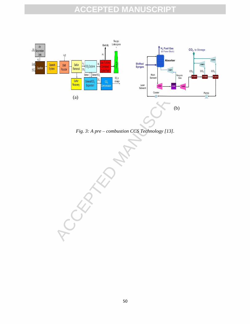
ACCEP
TED M
ANUSC
RIPT
50
(a)
(b)
Fig. 3: A pre – combustion CCS Technology [13].
ACCEPTED MANUSCRIPT
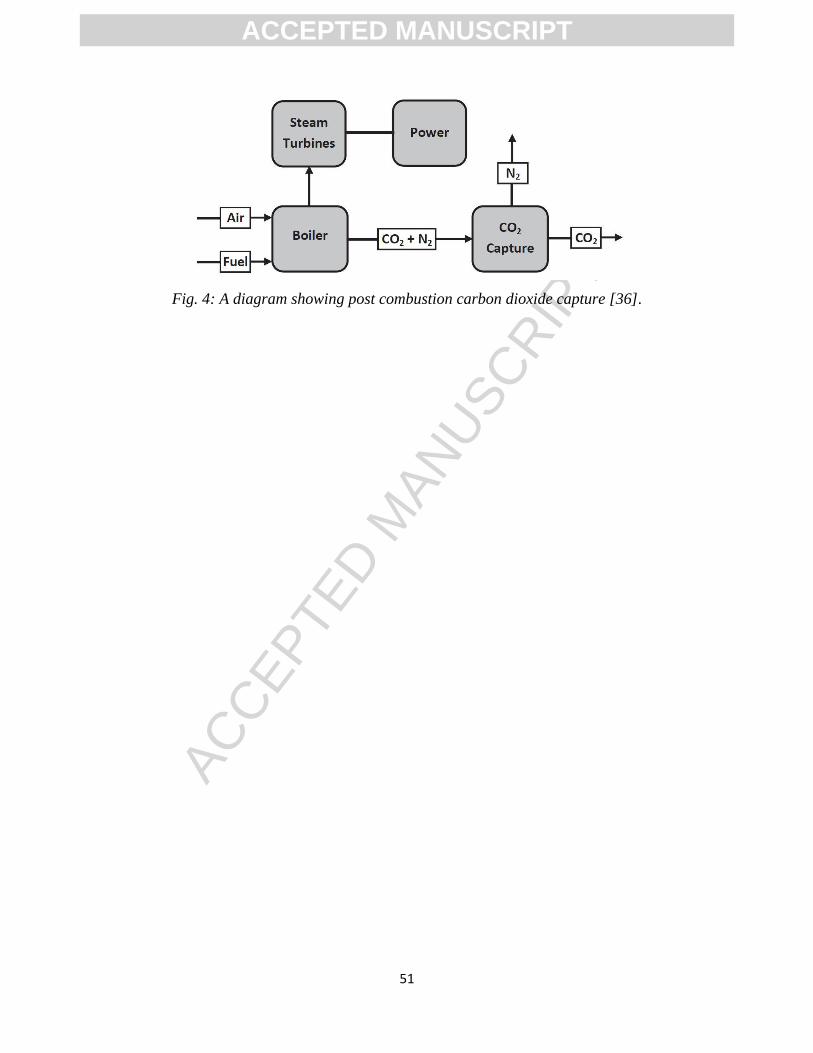
ACCEP
TED M
ANUSC
RIPT
51
Fig. 4: A diagram showing post combustion carbon dioxide capture [36].
ACCEPTED MANUSCRIPT
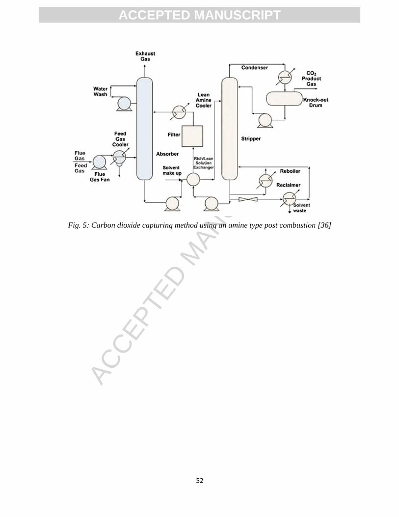
ACCEP
TED M
ANUSC
RIPT
52
Fig. 5: Carbon dioxide capturing method using an amine type post combustion [36]
ACCEPTED MANUSCRIPT

ACCEP
TED M
ANUSC
RIPT
53
Fig. 6: Diagram showing an amine based post – combustion CO2 capturing system for NGCC
[36]
ACCEPTED MANUSCRIPT
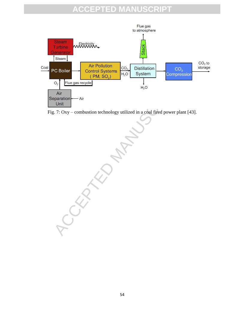
ACCEP
TED M
ANUSC
RIPT
54
Fig. 7: Oxy – combustion technology utilized in a coal fired power plant [43].
ACCEPTED MANUSCRIPT
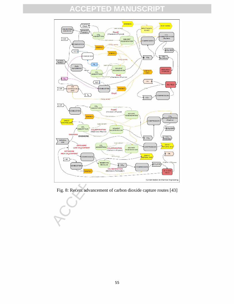
ACCEP
TED M
ANUSC
RIPT
55
Fig. 8: Recent advancement of carbon dioxide capture routes [43]
ACCEPTED MANUSCRIPT
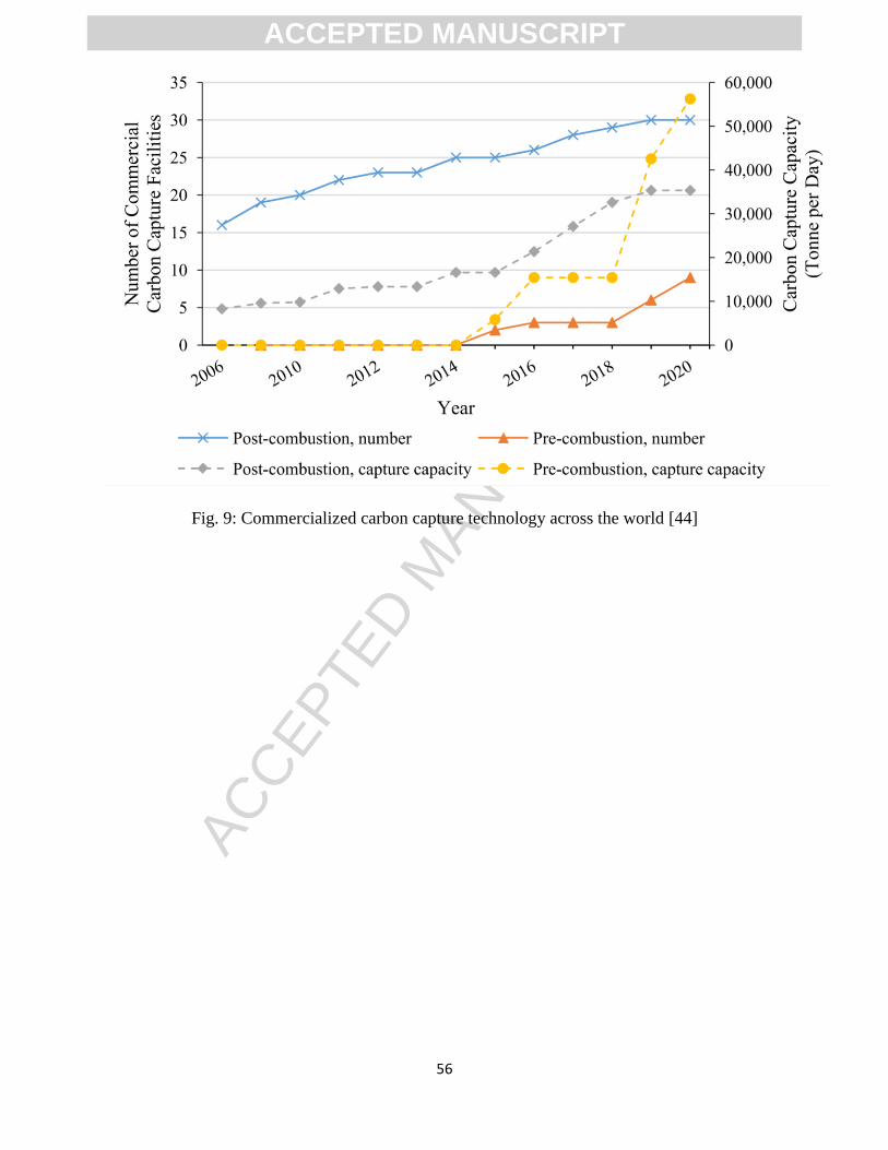
ACCEP
TED M
ANUSC
RIPT
56
Fig. 9: Commercialized carbon capture technology across the world [44]
ACCEPTED MANUSCRIPT
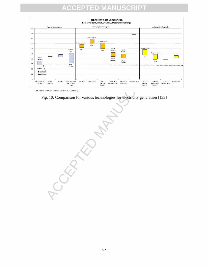
ACCEP
TED M
ANUSC
RIPT
57
Fig. 10: Comparison for various technologies for electricity generation [133]
ACCEPTED MANUSCRIPT
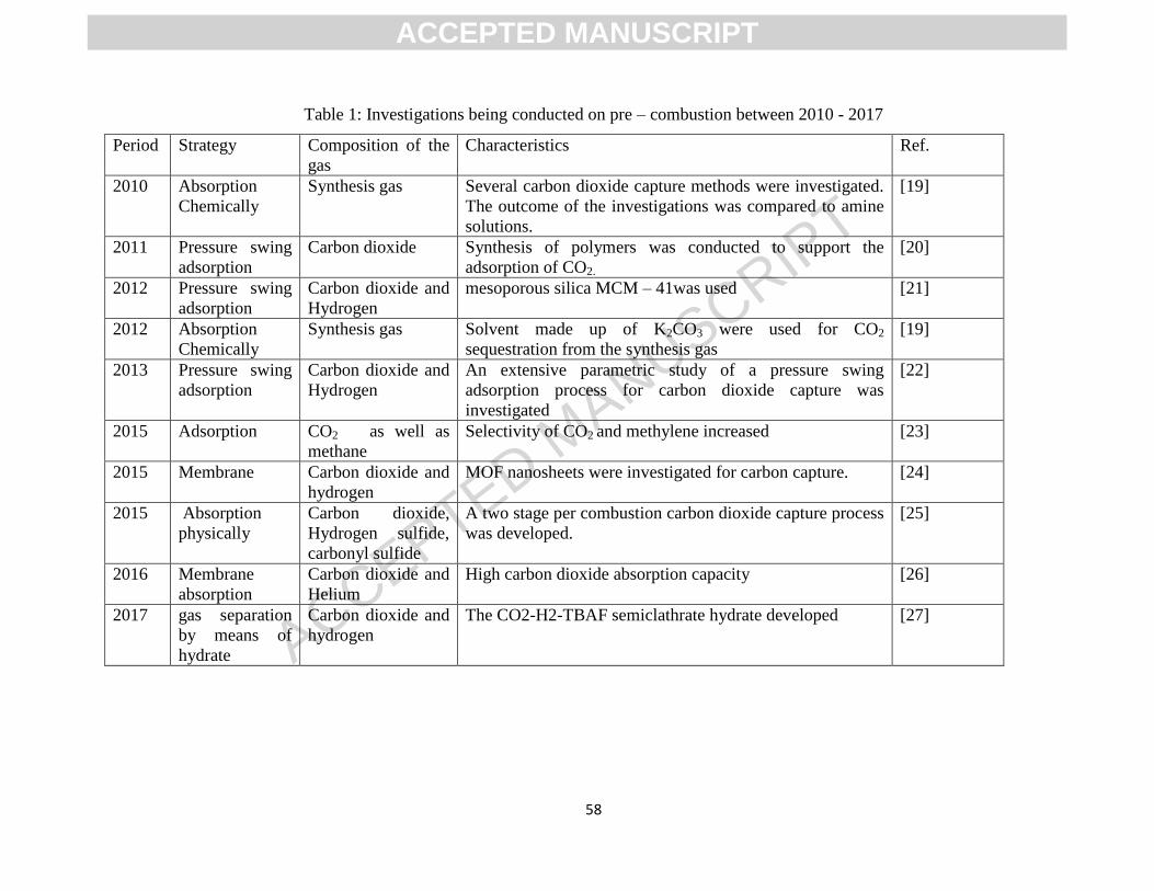
ACCEPTED MANUSCRIPT
58
Table 1: Investigations being conducted on pre – combustion between 2010 - 2017
Period Strategy Composition of the
gas
Characteristics Ref.
2010 Absorption
Chemically
Synthesis gas Several carbon dioxide capture methods were investigated.
The outcome of the investigations was compared to amine
solutions.
[19]
2011 Pressure swing
adsorption
Carbon dioxide Synthesis of polymers was conducted to support the
adsorption of CO2.
[20]
2012 Pressure swing
adsorption
Carbon dioxide and
Hydrogen
mesoporous silica MCM – 41was used [21]
2012 Absorption
Chemically
Synthesis gas Solvent made up of K2CO3 were used for CO2
sequestration from the synthesis gas
[19]
2013 Pressure swing
adsorption
Carbon dioxide and
Hydrogen
An extensive parametric study of a pressure swing
adsorption process for carbon dioxide capture was
investigated
[22]
2015 Adsorption CO2 as well as
methane
Selectivity of CO2 and methylene increased [23]
2015 Membrane Carbon dioxide and
hydrogen
MOF nanosheets were investigated for carbon capture. [24]
2015 Absorption
physically
Carbon dioxide,
Hydrogen sulfide,
carbonyl sulfide
A two stage per combustion carbon dioxide capture process
was developed.
[25]
2016 Membrane
absorption
Carbon dioxide and
Helium
High carbon dioxide absorption capacity [26]
2017 gas separation
by means of
hydrate
Carbon dioxide and
hydrogen
The CO2-H2-TBAF semiclathrate hydrate developed [27]
ACCEPTED MANUSCRIPT
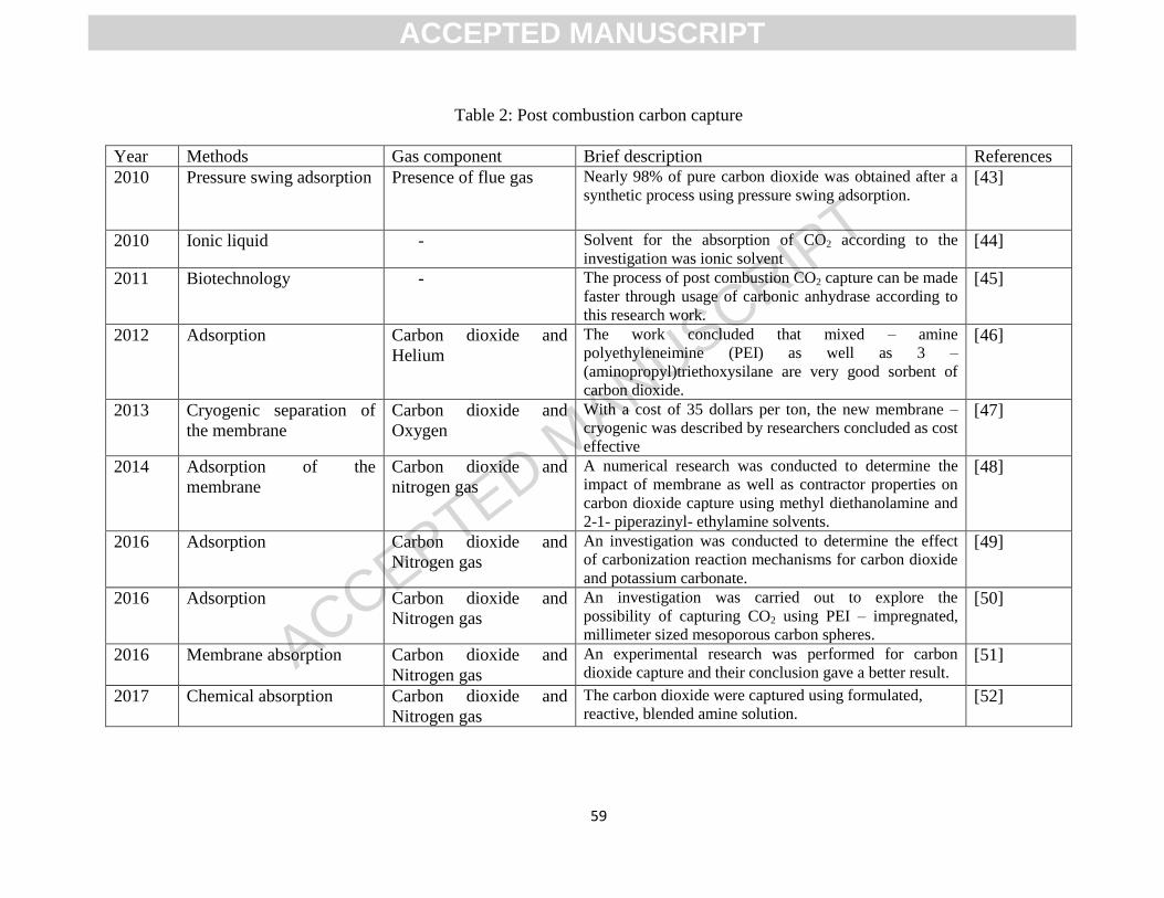
ACCEPTED MANUSCRIPT
59
Table 2: Post combustion carbon capture
Year Methods Gas component Brief description References
2010 Pressure swing adsorption Presence of flue gas Nearly 98% of pure carbon dioxide was obtained after a
synthetic process using pressure swing adsorption. [43]
2010 Ionic liquid - Solvent for the absorption of CO2 according to the
investigation was ionic solvent [44]
2011 Biotechnology - The process of post combustion CO2 capture can be made
faster through usage of carbonic anhydrase according to
this research work.
[45]
2012 Adsorption Carbon dioxide and
Helium
The work concluded that mixed – amine
polyethyleneimine (PEI) as well as 3 –
(aminopropyl)triethoxysilane are very good sorbent of
carbon dioxide.
[46]
2013 Cryogenic separation of
the membrane
Carbon dioxide and
Oxygen
With a cost of 35 dollars per ton, the new membrane –
cryogenic was described by researchers concluded as cost
effective
[47]
2014 Adsorption of the
membrane
Carbon dioxide and
nitrogen gas
A numerical research was conducted to determine the
impact of membrane as well as contractor properties on
carbon dioxide capture using methyl diethanolamine and
2-1- piperazinyl- ethylamine solvents.
[48]
2016 Adsorption Carbon dioxide and
Nitrogen gas
An investigation was conducted to determine the effect
of carbonization reaction mechanisms for carbon dioxide
and potassium carbonate.
[49]
2016 Adsorption Carbon dioxide and
Nitrogen gas
An investigation was carried out to explore the
possibility of capturing CO2 using PEI – impregnated,
millimeter sized mesoporous carbon spheres.
[50]
2016 Membrane absorption Carbon dioxide and
Nitrogen gas
An experimental research was performed for carbon
dioxide capture and their conclusion gave a better result. [51]
2017 Chemical absorption Carbon dioxide and
Nitrogen gas
The carbon dioxide were captured using formulated,
reactive, blended amine solution. [52]
ACCEPTED MANUSCRIPT
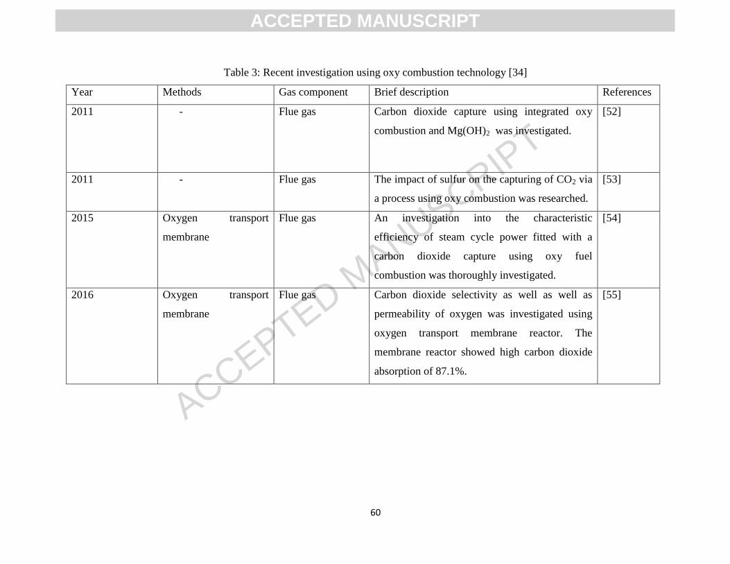
ACCEPTED MANUSCRIPT
60
Table 3: Recent investigation using oxy combustion technology [34]
Year Methods Gas component Brief description References
2011 - Flue gas Carbon dioxide capture using integrated oxy
combustion and Mg(OH)2 was investigated.
[52]
2011 - Flue gas The impact of sulfur on the capturing of CO2 via
a process using oxy combustion was researched.
[53]
2015 Oxygen transport
membrane
Flue gas An investigation into the characteristic
efficiency of steam cycle power fitted with a
carbon dioxide capture using oxy fuel
combustion was thoroughly investigated.
[54]
2016 Oxygen transport
membrane
Flue gas Carbon dioxide selectivity as well as well as
permeability of oxygen was investigated using
oxygen transport membrane reactor. The
membrane reactor showed high carbon dioxide
absorption of 87.1%.
[55]
ACCEPTED MANUSCRIPT
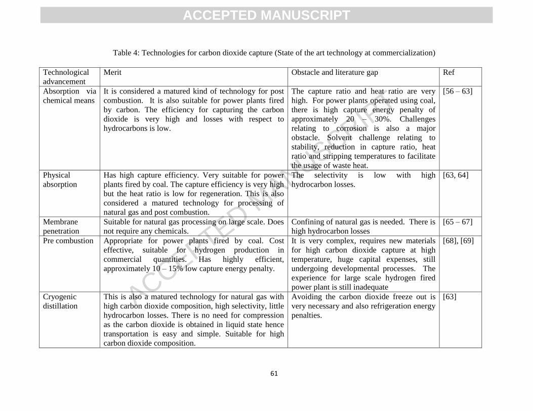
ACCEPTED MANUSCRIPT
61
Table 4: Technologies for carbon dioxide capture (State of the art technology at commercialization)
Technological
advancement
Merit Obstacle and literature gap Ref
Absorption via
chemical means
It is considered a matured kind of technology for post
combustion. It is also suitable for power plants fired
by carbon. The efficiency for capturing the carbon
dioxide is very high and losses with respect to
hydrocarbons is low.
The capture ratio and heat ratio are very
high. For power plants operated using coal,
there is high capture energy penalty of
approximately 20 – 30%. Challenges
relating to corrosion is also a major
obstacle. Solvent challenge relating to
stability, reduction in capture ratio, heat
ratio and stripping temperatures to facilitate
the usage of waste heat.
[56 – 63]
Physical
absorption
Has high capture efficiency. Very suitable for power
plants fired by coal. The capture efficiency is very high
but the heat ratio is low for regeneration. This is also
considered a matured technology for processing of
natural gas and post combustion.
The selectivity is low with high
hydrocarbon losses.
[63, 64]
Membrane
penetration
Suitable for natural gas processing on large scale. Does
not require any chemicals.
Confining of natural gas is needed. There is
high hydrocarbon losses
[65 – 67]
Pre combustion Appropriate for power plants fired by coal. Cost
effective, suitable for hydrogen production in
commercial quantities. Has highly efficient,
approximately 10 – 15% low capture energy penalty.
It is very complex, requires new materials
for high carbon dioxide capture at high
temperature, huge capital expenses, still
undergoing developmental processes. The
experience for large scale hydrogen fired
power plant is still inadequate
[68], [69]
Cryogenic
distillation
This is also a matured technology for natural gas with
high carbon dioxide composition, high selectivity, little
hydrocarbon losses. There is no need for compression
as the carbon dioxide is obtained in liquid state hence
transportation is easy and simple. Suitable for high
carbon dioxide composition.
Avoiding the carbon dioxide freeze out is
very necessary and also refrigeration energy
penalties.
[63]
ACCEPTED MANUSCRIPT

ACCEPTED MANUSCRIPT
62
Table 5: Other technology for carbon capture but with insufficient large-scale experience
Technological
advancement
Characteristics Merits Ref
Hybrids High carbon dioxide elimination via cryogenic
distillation.
The cost is very low, and the capture energy penalty is
low as well
[70]
Enhancement of
chemical or
physical
absorption
Flowsheets are complex and requires mixed
solvents.
The solvents have high efficiency
Hybrid solvents
Requires solvents that are anhydrous.
Ionic liquid
Solvents that undergoes phase change
carbon dioxide solventing out requires adding
other solvent that are inert
solvents that are organic
The equivalent work needed is 12% less compared to
a stripper. There is high heat ratio reduction because
of the usage of the mixed solvents instead of MEA in
liquified state. The thermochemical stability is very
high.
Reduced heat ratio
The challenge in relation to high parasitic energy
consumption regarding water is reduced.
Reduced heat ratio, reduced evaporation losses.
Reduced heat ratio, loading of the carbon dioxide
results in phase change.
Requires using recycled heat
Low heat ratio
[71]
[72]
[73]
[74]
[75]
[76]
[77]
[61]
ACCEPTED MANUSCRIPT

ACCEPTED MANUSCRIPT
63
[78]
Membrane
penetration
New membrane materials
Integrated membrane material as well as
process development for gas separation
Multi stage schemes
The sweep agent used is steam.
Solvent supported membrane
High flux but the exhaust gases have low pressure but
high carbon dioxide.
Sustainable membrane permeability
Highly efficient
Efficient permeate elimination, avoiding carbon
dioxide buildup,.
volatility of solvent negligible (ionic liquids and deep
eutectic solvents) to enhance selectivity.
[79]
[80,
81]
[82]
[83]
[84]
[85]
Gas liquid
membrane
Characterization and performance of various
membrane materials
Highly efficient, [86]
Adsorption Novel sorbent materials High surface area. [74]
Oxy combustion Makes post combustion capture simplified and
also very efficient.
Highly efficient [87]
Chemical looping
burning
Uses metal oxide Lower capturing energy cost [88]
Mineralization Converting solid material Commercialized [89]
ACCEPTED MANUSCRIPT
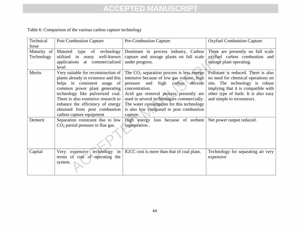
ACCEPTED MANUSCRIPT
64
Table 6: Comparison of the various carbon capture technology
Technical
Issue
Post Combustion Capture Pre-Combustion Capture Oxyfuel Combustion Capture
Maturity of
Technology
Matured type of technology
utilized in many well-known
applications at commercialized
level
Dominant in process industry. Carbon
capture and storage plants on full scale
under progress.
There are presently no full scale
oxyfuel carbon combustion and
storage plant operating.
Merits Very suitable for reconstruction of
plants already in existence and this
helps in consistent usage of
common power plant generating
technology like pulverized coal.
There is also extensive research to
enhance the efficiency of energy
obtained from post combustion
carbon capture equipment
The CO2 separation process is less energy
intensive because of low gas volume, high
pressure and high carbon dioxide
concentration.
Acid gas removal process presently are
used in several technologies commercially.
The water consumption for this technology
is also low compared to post combustion
capture.
Pollutant is reduced. There is also
no need for chemical operations on
site. The technology is robust
implying that it is compatible with
other type of fuels. It is also easy
and simple to reconstruct.
Demerit Separation constraint due to low
CO2 partial pressure in flue gas.
High energy loss because of sorbent
regeneration .
Net power output reduced .
Capital Very expensive technology in
terms of cost of operating the
system.
IGCC cost is more than that of coal plant.
Technology for separating air very
expensive
ACCEPTED MANUSCRIPT
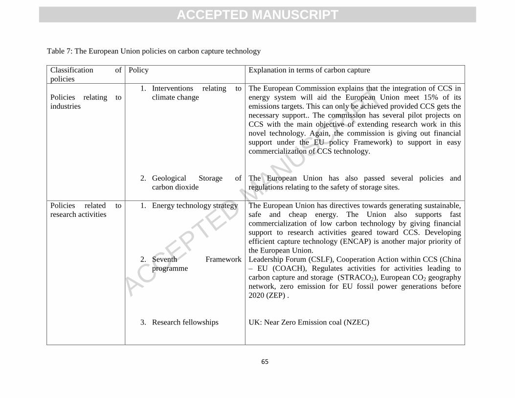
ACCEPTED MANUSCRIPT
65
Table 7: The European Union policies on carbon capture technology
Classification of
policies
Policy Explanation in terms of carbon capture
Policies relating to
industries
1. Interventions relating to
climate change
2. Geological Storage of
carbon dioxide
The European Commission explains that the integration of CCS in
energy system will aid the European Union meet 15% of its
emissions targets. This can only be achieved provided CCS gets the
necessary support.. The commission has several pilot projects on
CCS with the main objective of extending research work in this
novel technology. Again, the commission is giving out financial
support under the EU policy Framework) to support in easy
commercialization of CCS technology.
The European Union has also passed several policies and
regulations relating to the safety of storage sites.
Policies related to
research activities
1. Energy technology strategy
2. Seventh Framework
programme
3. Research fellowships
The European Union has directives towards generating sustainable,
safe and cheap energy. The Union also supports fast
commercialization of low carbon technology by giving financial
support to research activities geared toward CCS. Developing
efficient capture technology (ENCAP) is another major priority of
the European Union.
Leadership Forum (CSLF), Cooperation Action within CCS (China
– EU (COACH), Regulates activities for activities leading to
carbon capture and storage (STRACO2), European CO2 geography
network, zero emission for EU fossil power generations before
2020 (ZEP) .
UK: Near Zero Emission coal (NZEC)
ACCEPTED MANUSCRIPT
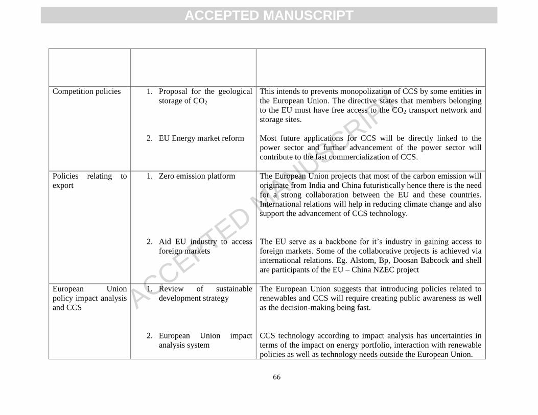
ACCEPTED MANUSCRIPT
66
Competition policies 1. Proposal for the geological
storage of CO2
2. EU Energy market reform
This intends to prevents monopolization of CCS by some entities in
the European Union. The directive states that members belonging
to the EU must have free access to the CO2 transport network and
storage sites.
Most future applications for CCS will be directly linked to the
power sector and further advancement of the power sector will
contribute to the fast commercialization of CCS.
Policies relating to
export
1. Zero emission platform
2. Aid EU industry to access
foreign markets
The European Union projects that most of the carbon emission will
originate from India and China futuristically hence there is the need
for a strong collaboration between the EU and these countries.
International relations will help in reducing climate change and also
support the advancement of CCS technology.
The EU serve as a backbone for it’s industry in gaining access to
foreign markets. Some of the collaborative projects is achieved via
international relations. Eg. Alstom, Bp, Doosan Babcock and shell
are participants of the EU – China NZEC project
European Union
policy impact analysis
and CCS
1. Review of sustainable
development strategy
2. European Union impact
analysis system
The European Union suggests that introducing policies related to
renewables and CCS will require creating public awareness as well
as the decision-making being fast.
CCS technology according to impact analysis has uncertainties in
terms of the impact on energy portfolio, interaction with renewable
policies as well as technology needs outside the European Union.
ACCEPTED MANUSCRIPT

ACCEPTED MANUSCRIPT
67
3. Environmental assessment
directive
4. Environmental impact
analysis
The approach adopted in the evaluation of strategic environmental
impacts of CCS remain uncertain.
Environmental impact analysis is aimed at specific project
evaluation and it has been applied to evaluate CCS demonstration
projects.
ACCEPTED MANUSCRIPT
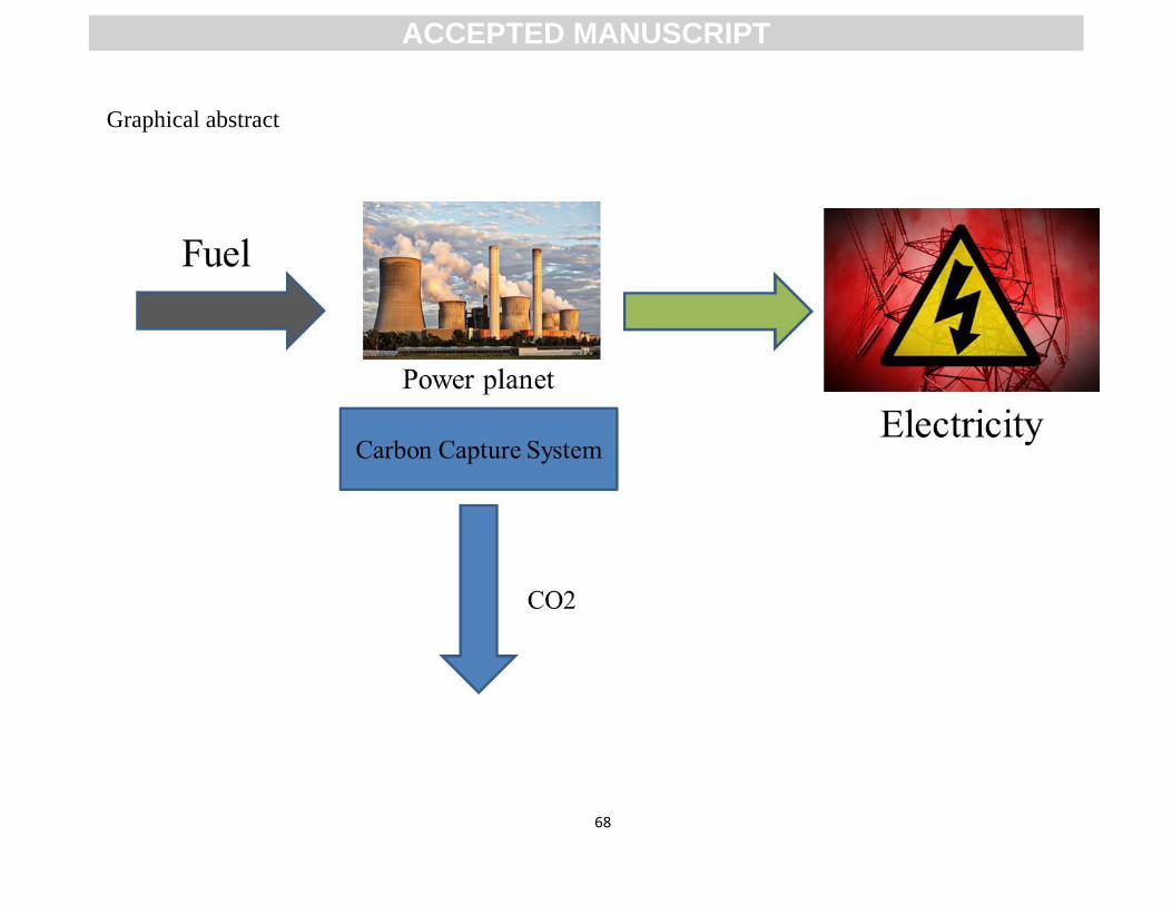
ACCEPTED MANUSCRIPT
68
Graphical abstract
ACCEPTED MANUSCRIPT

ACCEPTED MANUSCRIPT
69
Highlights
1. The main carbon capture technologies are reviewed
2. Comparison between the types of carbon capture technology is presented
3. Challenges of using these technologies in the capture of carbon dioxide is discussed
4. Future prospects of some of these technologies is presented.
ACCEPTED MANUSCRIPT