Embed Size (px)
Citation preview
12/9/2016
1
Preservation and Renewal of Civil Engineering Infrastructure Using FRP Composites
City University of LondonLondon, UK
December 7, 2016
Abdeldjelil Belarbi, PhD, PE, FACI, FASCE, FSEIDistinguished Professor of Civil Engineering
1. Introduction
2. CurrentChallengesandIssuesatHand
3. Fiber‐ReinforcedPolymers (FRP)
4. ShearStrengthening
5. SoftenedMembraneModel
6. ConcludingRemarks
2
12/9/2016
OUTLINE OF THE PRESENTATION

12/9/2016
2
3
WHERE IN THE WORLD ARE HOUSTON AND TEXAS?
• Houston
• Texas is the second largest state in the USA.
• It shares border with Mexico.
• The capital city is Austin
• 26 million people live in Texas.12/9/2016
Texas has a wide variety of landscapes, includingcoastal, mountains, planes, and desert.
TEXAS LANDSCAPE
4
12/9/2016

12/9/2016
3
TEXAS ECONOMY
Texas is an importantpart of the U.S. economy. It is the second wealthieststate in the country.
Important sectors of theTexas economy include oiland gas, agriculture and mining, energy, technology, and commerce.
5
12/9/2016
6
Houston City - The Basics
• America’s 3rd/4th largest city
• Over 4 million residents
• Energy Capital of the World
• No ethnic majority
• 83 languages spoken
• “Houston” – First Word Spoken from the Moon
12/9/2016

12/9/2016
4
7
1873
12/9/2016
8
21st Century
12/9/2016

12/9/2016
5
9
The University of Houston (UH) is a state research university and the flagship institution of
the University of Houston System
UNIVERSITY OFHOUSTON
12/9/2016
Founded in 1927UH is the third largest university in Texas
with more than 41,000 students.
UH is the second most ethnically diverse major research university in the United States.
Students come to UH from more than 137 nations
UH offers more than 120 undergraduate majors,139 master’s, and 54 doctoral degrees.
UH has 980 ranked faculty, 1340 non‐ranked faculty, and 1450 student teaching assistants
10
12/9/2016

12/9/2016
6
The University of Houston comprises 12 academic colleges and an interdisciplinary Honors College.
Gerald D. Hines College of ArchitectureC.T. Bauer College of BusinessCollege of EducationCullen College of EngineeringHonors CollegeConrad N. Hilton College of Hotel andUH Law CenterCollege of Liberal Arts & Social SciencesCollege of Natural Sciences & MathematicsCollege of OptometryCollege of PharmacyGraduate College of Social WorkCollege of Technology
11
12/9/2016
UH Cullen College of Engineering
Dept. of Civil and Environmental Engineering Dept. of Electrical and Computer Engineering Dept. of Chemical Engineering Dept. of Petroleum Engineering Dept. of Biomedical Engineering Dept. of Industrial Engineering
Interdisciplinary Graduate Programs in
Materials engineering Subsea Engineering Aerospace Engineering Geosensing Engineering Environmental Engineering
www.uh.edu12
12/9/2016

12/9/2016
7
Milestones of architecture and civil engineering
1‐ Introduction
12/9/2016
13
“If a builder build a house for some one, and does not construct it properly, and the house which he built fall in and kill its owner, then that builder shall be put to death.”
Code of Hammurabi – 1772 BC
1‐ Introduction
12/9/2016
14

12/9/2016
8
15
3700 BCEAncient
Mesopotania
3150 BCEAncient Egypt
2900 BCEAncient India
900 BCEAncient Greeks
1850 BCEAncient China
800BCEAncient Rome
650 BCEPersian Empire
150 ADMayan Civilization 1800
RC/PC/FRP….
Present
Conventional construction materials of today started to appear.‐ Portland cement concrete‐ Reinforced concrete ‐ Prestressed concrete‐ Advanced composites and plastics‐ What is next???
1‐ Introduction
12/9/2016
Reinforced Concrete details ‐Monier System 1867
The birth of reinforced Concrete
1‐ Introduction
12/9/2016
16

12/9/2016
9
Reinforced Concrete
The Burj Khalifa (United ArabEmirates) is the tallest man-made structure ever built (as oftoday). It is supported by areinforced concrete core usinga special concrete mix.
istockphoto.com
1‐ Introduction
12/9/2016
17
1925 1950 1975 20001825 1850 1875 1900 2025
1867J. Monier
1957Montaso
1933E. Freyssinet
Reinforced Concrete
RC vs PC vs FRP
FRPPrestressed Concrete
Portland Cement
1824 J. Aspdin
Two centuries full of technological breakthrough
18
ACI Building Code
EuroCode
CEB/FIB AASHTO
PCIACI 440
1‐ Introduction
12/9/2016

12/9/2016
10
Man constructs,Man destructs,Man constructs…
Source: http://whateverhappensny.bandcamp.com/releases
2‐CurrentChallengesandIssuesatHand
19
12/9/2016
WW II – Mass destruction of built environment and infrastructure of cities all around the world.
Hiroshima – Japan, 1945
Warsaw, Poland
1935 1945 2009
2‐CurrentChallengesandIssuesatHand
20
12/9/2016
12/9/2016
11
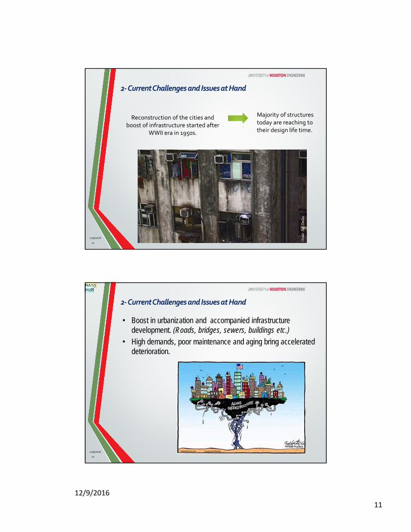
Reconstruction of the cities and boost of infrastructure started after
WWII era in 1950s.
Majority of structures today are reaching to their design life time.
2‐CurrentChallengesandIssuesatHand
21
12/9/2016
22
• Boost in urbanization and accompanied infrastructure development. (Roads, bridges, sewers, buildings etc.)
• High demands, poor maintenance and aging bring accelerated deterioration.
2‐CurrentChallengesandIssuesatHand
12/9/2016
BA10mz8

12/9/2016
12
23
2000’s
1950’s
A great number of US bridges have become structurally deficient or functionally obsolete due to:
Changing traffic demands
2‐CurrentChallengesandIssuesatHand
12/9/2016
BA11mz9
24
Change of use: Higher loads than originally designed
2‐CurrentChallengesandIssuesatHand
12/9/2016
BA17mz13
12/9/2016
13
25
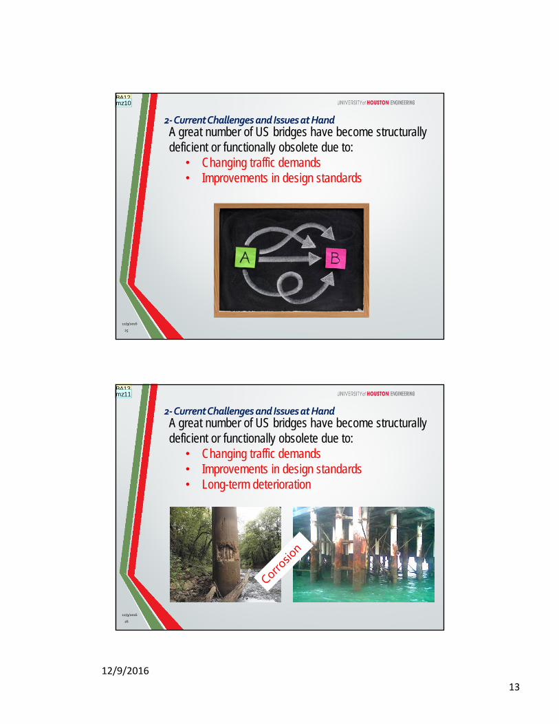
A great number of US bridges have become structurally deficient or functionally obsolete due to:
• Changing traffic demands• Improvements in design standards
2‐CurrentChallengesandIssuesatHand
12/9/2016
BA12mz10
26
A great number of US bridges have become structurally deficient or functionally obsolete due to:
• Changing traffic demands• Improvements in design standards• Long-term deterioration
2‐CurrentChallengesandIssuesatHand
12/9/2016
BA13mz11
12/9/2016
14
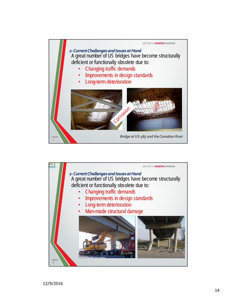
Bridge at US‐385 and the Canadian River12/9/2016
27
A great number of US bridges have become structurally deficient or functionally obsolete due to:
• Changing traffic demands• Improvements in design standards• Long-term deterioration
2‐CurrentChallengesandIssuesatHand
28
A great number of US bridges have become structurally deficient or functionally obsolete due to:
• Changing traffic demands• Improvements in design standards• Long-term deterioration• Man-made structural damage
2‐CurrentChallengesandIssuesatHand
12/9/2016
BA14mz12
12/9/2016
15
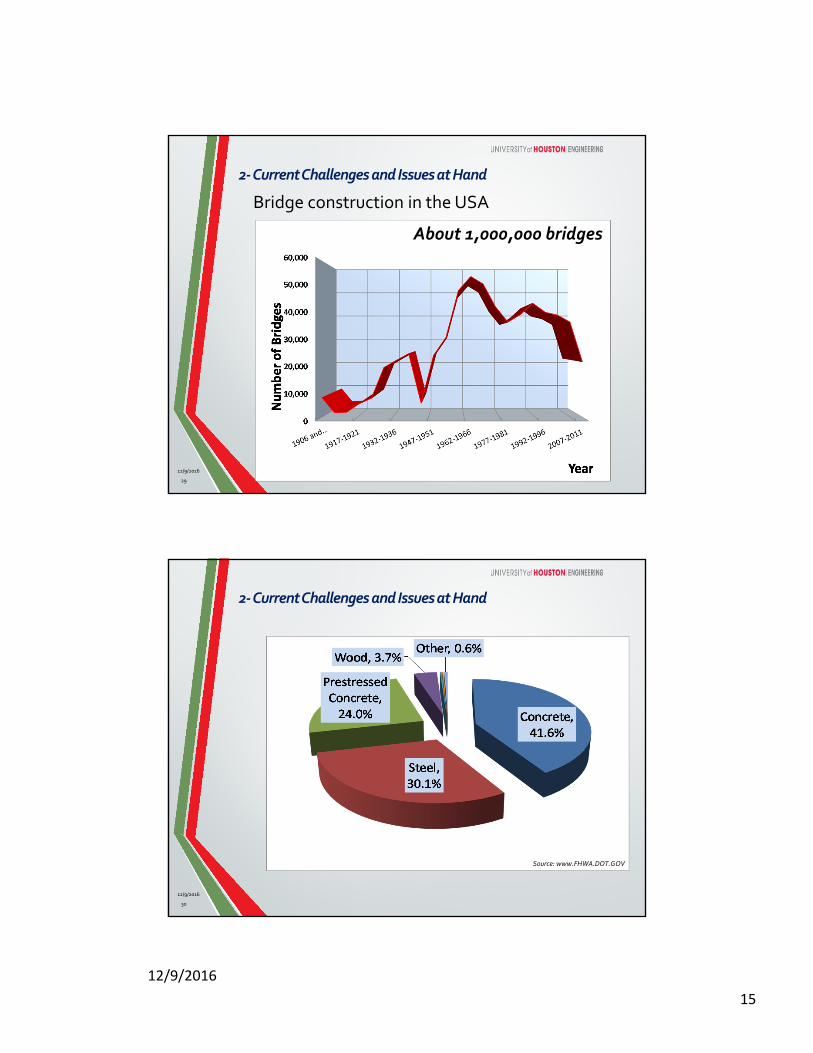
Bridge construction in the USA
2‐CurrentChallengesandIssuesatHand
29
About 1,000,000 bridges
12/9/2016
• ASCE 2013 Report Card for Bridges:
C+• Need to invest $20.5 billion annually till 2028
75%
Source: www.FHWA.DOT.GOV
2‐CurrentChallengesandIssuesatHand
30
12/9/2016
12/9/2016
16
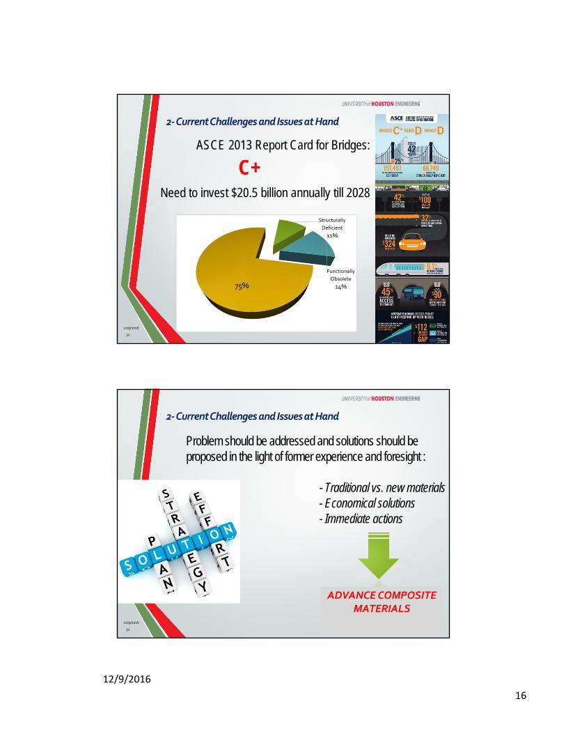
75%
Structurally
Deficient
11%
Functionally
Obsolete
14%75%
2‐CurrentChallengesandIssuesatHand
ASCE 2013 Report Card for Bridges:
C+Need to invest $20.5 billion annually till 2028
31
12/9/2016
Problem should be addressed and solutions should be proposed in the light of former experience and foresight :
- Traditional vs. new materials - Economical solutions- Immediate actions
ADVANCE COMPOSITE MATERIALS
2‐CurrentChallengesandIssuesatHand
32
12/9/2016

12/9/2016
17
Nationally recognized need
2‐CurrentChallengesandIssuesatHand
34
FRPs are advanced composite materials consisting of high strength fibers such as aramid, carbon or glass embedded in a polymer resin.
Commercially available forms
Reinforcing Bar and Prestressing Tendons
Pre-cured laminate shells
Grids
Fiber sheets
3‐Fiber‐ReinforcedPolymers (FRP)
12/9/2016
BA22mz14
12/9/2016
18
35
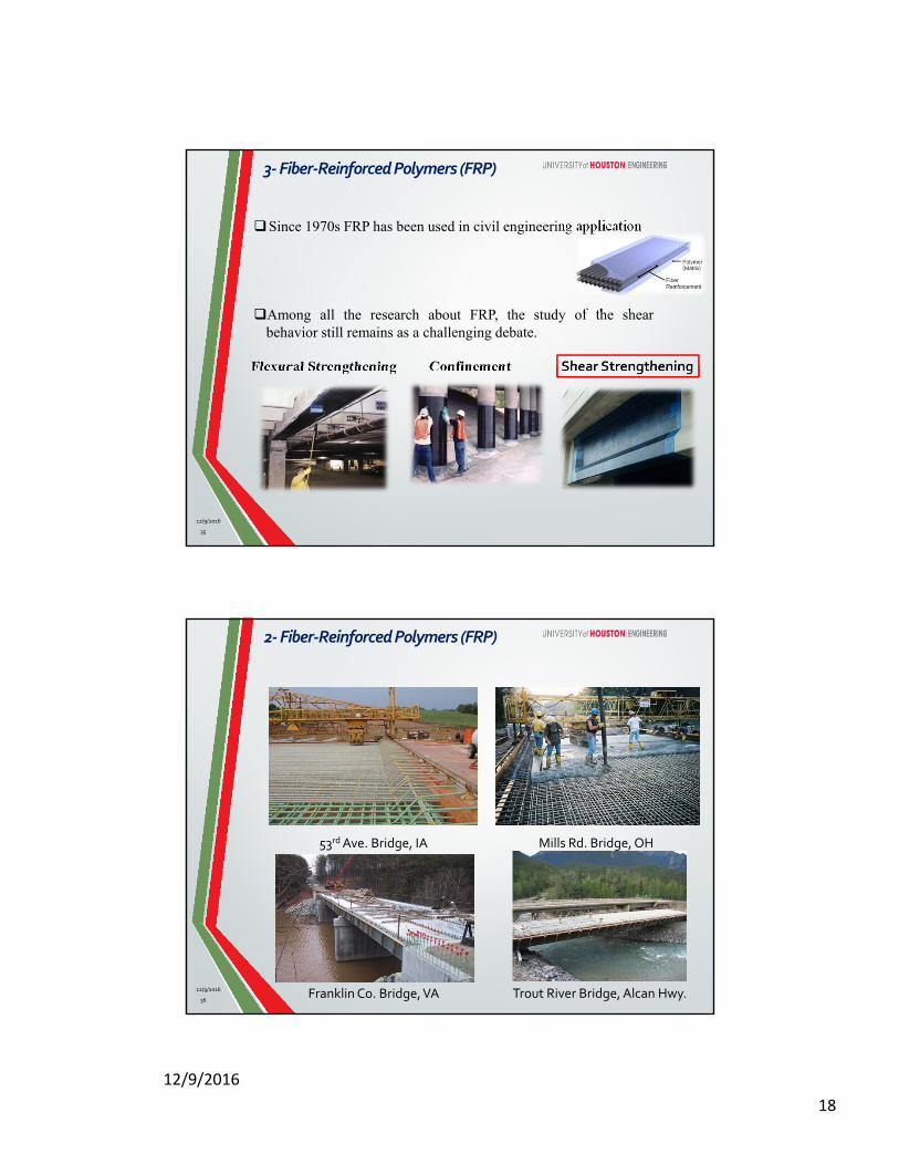
Flexural Strengthening Confinement Shear Strengthening
Since 1970s FRP has been used in civil engineering application
Among all the research about FRP, the study of the shearbehavior still remains as a challenging debate.
3‐Fiber‐ReinforcedPolymers (FRP)
12/9/2016
53rd Ave. Bridge, IA Mills Rd. Bridge, OH
Franklin Co. Bridge, VA Trout River Bridge, Alcan Hwy.12/9/2016
36
2‐Fiber‐ReinforcedPolymers (FRP)
12/9/2016
19
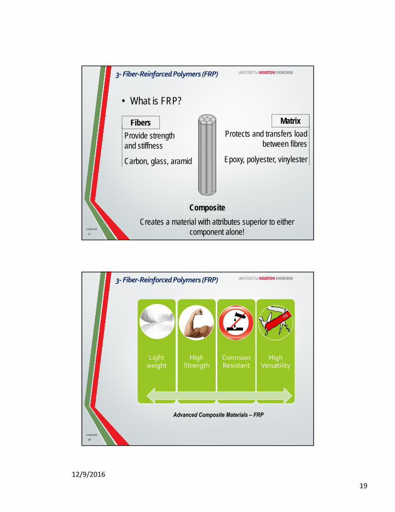
• What is FRP?
Fibers
Provide strength and stiffness
Carbon, glass, aramid
Matrix
Protects and transfers load between fibres
Epoxy, polyester, vinylester
Composite
Creates a material with attributes superior to either component alone!37
3‐Fiber‐ReinforcedPolymers (FRP)
12/9/2016
Light weight
High Strength
Corrosion Resistant
High Versatility
Advanced Composite Materials – FRP
38
3‐Fiber‐ReinforcedPolymers (FRP)
12/9/2016

12/9/2016
20
FRP properties (compared to steel reinforcement):• Linear elastic
• No yielding
• Higher ultimate strength
• Lower strain at failure1 ksi = 6.89 MPa
39
3‐Fiber‐ReinforcedPolymers (FRP)
12/9/2016
Limitations :Higher CostAnisotropyBrittle BehaviorComplex CharacterizationLack of Comprehensive
Standard Design Codes (emerging)
40
3‐Fiber‐ReinforcedPolymers (FRP)
12/9/2016
12/9/2016
21
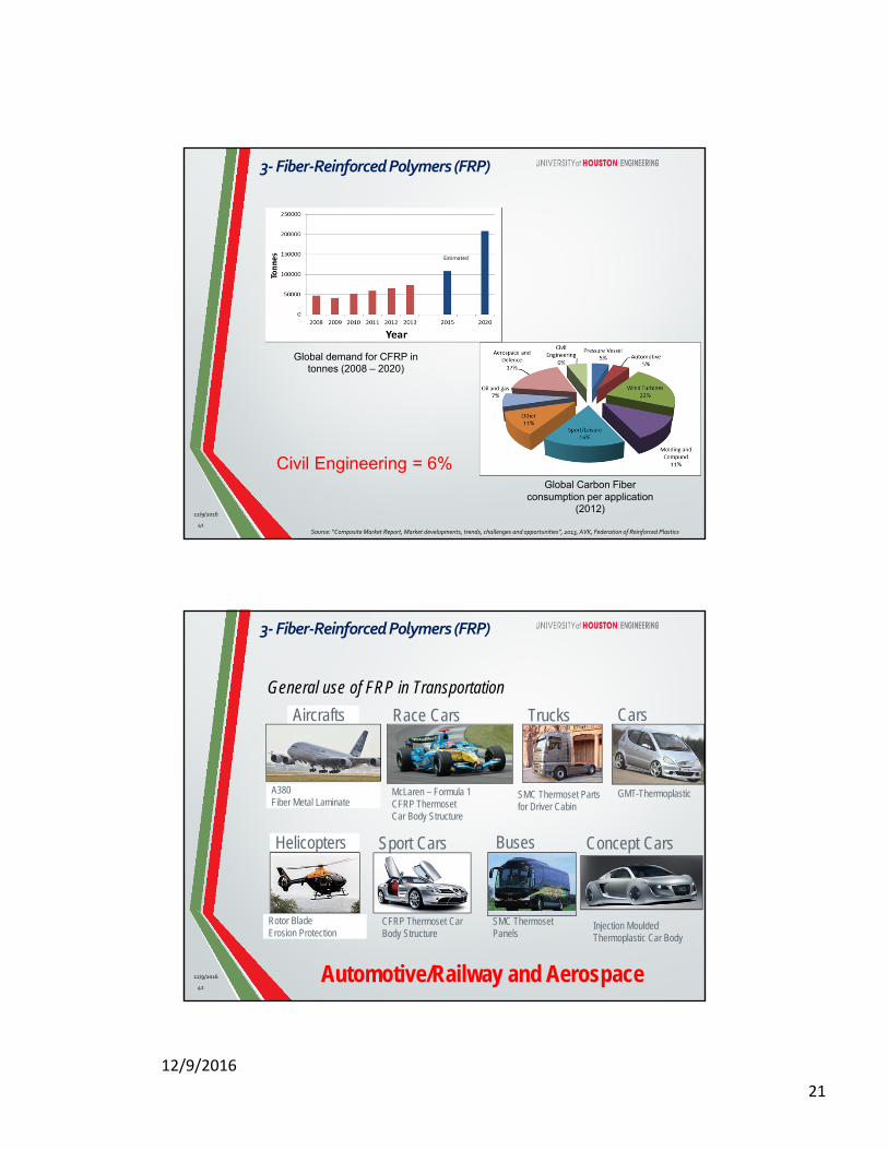
Global demand for CFRP in tonnes (2008 – 2020)
Civil Engineering = 6%
Estimated
Global Carbon Fiber consumption per application
(2012)
Source: “Composite Market Report, Market developments, trends, challenges and opportunities”, 2013, AVK, Federation of Reinforced Plastics 41
3‐Fiber‐ReinforcedPolymers (FRP)
12/9/2016
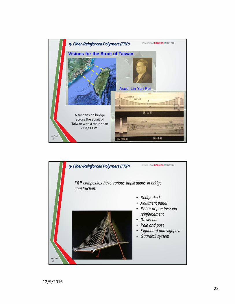
General use of FRP in Transportation
Aircrafts Race Cars Trucks Cars
Concept CarsBusesSport CarsHelicopters
A380Fiber Metal Laminate
McLaren – Formula 1CFRP ThermosetCar Body Structure
SMC Thermoset Parts for Driver Cabin
GMT-Thermoplastic
Rotor BladeErosion Protection
CFRP Thermoset Car Body Structure
SMC ThermosetPanels
Injection MouldedThermoplastic Car Body
Automotive/Railway and Aerospace42
3‐Fiber‐ReinforcedPolymers (FRP)
12/9/2016

12/9/2016
22
Airbus 380
CFRP
AFRP
CFRP
CFRP
GFRP
AEROSPACE INDUSTRY
3‐Fiber‐ReinforcedPolymers (FRP)
12/9/2016
43
Proposal for a carbon fiber-reinforced composite bridge across the Straight of Gibraltar at its narrowest site according to Meier (1987) as a cable net structure.
Spans: 3,100 – 8,400 m.The heights of the towers are approximately 850 and 1,250 m. above sea level
3‐Fiber‐ReinforcedPolymers (FRP)
12/9/2016
44
12/9/2016
23
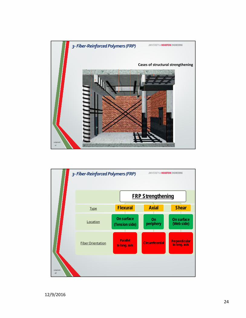
A suspension bridge across the Strait of
Taiwan with a main span of 3,500m.
3‐Fiber‐ReinforcedPolymers (FRP)
12/9/2016
45
• Bridge deck• Abutment panel• Rebar or prestressing
reinforcement• Dowel bar• Pole and post• Signboard and signpost• Guardrail system
FRP composites have various applications in bridge construction:
46
3‐Fiber‐ReinforcedPolymers (FRP)
12/9/2016
12/9/2016
24
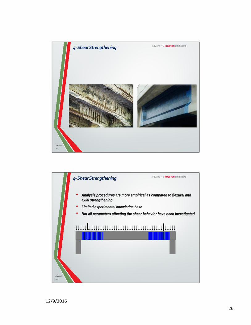
Cases of structural strengthening
47
3‐Fiber‐ReinforcedPolymers (FRP)
12/9/2016
Fiber Orientation
Location
Type
FRP Strengthening
Flexural
On surface(Tension side)
Parallel to long. axis
Axial
On periphery
Circumferential
Shear
On surface (Web side)
Perpendicular to long. axis
48
3‐Fiber‐ReinforcedPolymers (FRP)
12/9/2016

12/9/2016
25
Available Design
Guidelines Worldwide
ACI 440.2R-08
ISIS Canada Design Manual
European fib TG9.3 (2001)
CSA S806-12
3‐Fiber‐ReinforcedPolymers (FRP)
12/9/2016
49
Emerging Technologies Accepted Technologies12/9/2016
50
3‐Fiber‐ReinforcedPolymers (FRP)
12/9/2016
26
4‐ShearStrengthening
51
12/9/2016
4‐ShearStrengthening
• Analysis procedures are more empirical as compared to flexural and axial strengthening
• Limited experimental knowledge base
• Not all parameters affecting the shear behavior have been investigated
52
12/9/2016
12/9/2016
27
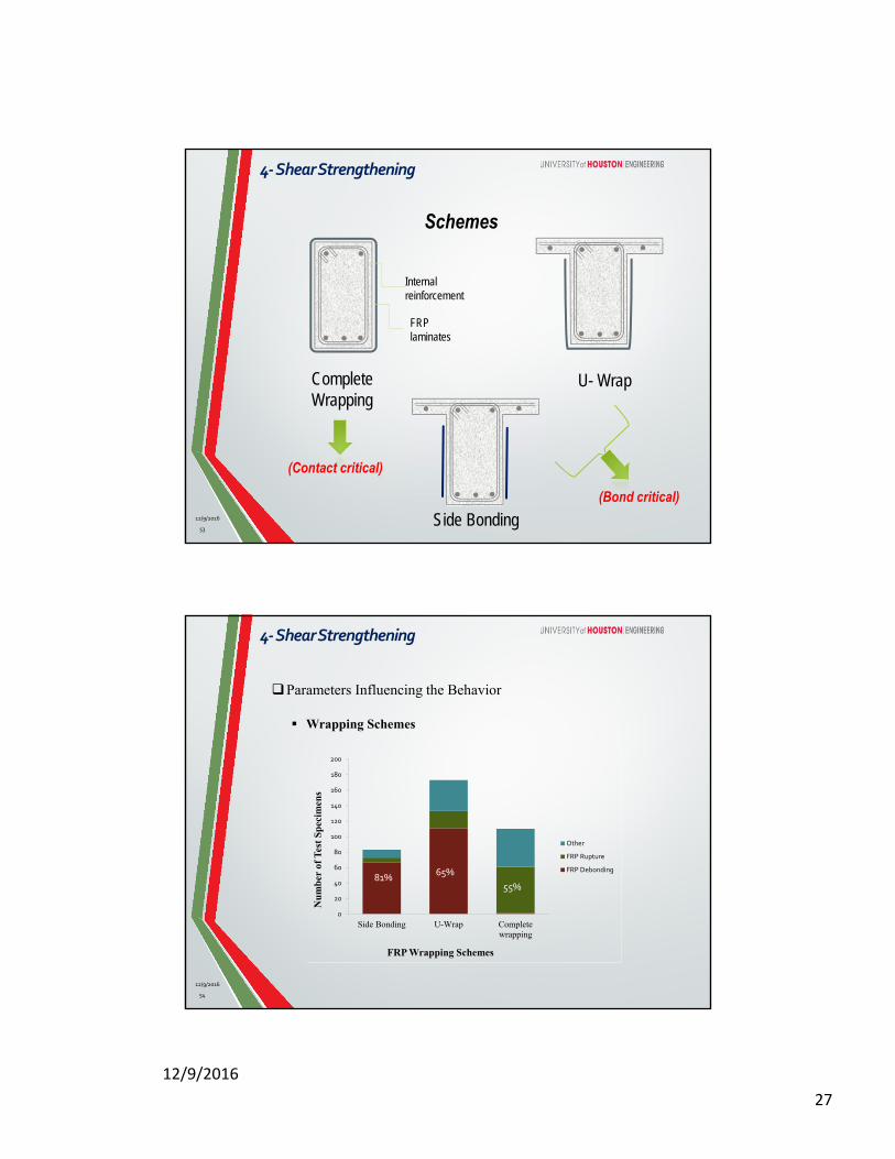
Internal reinforcement
FRP laminates
Complete Wrapping
U- Wrap
Side Bonding
(Contact critical)
(Bond critical)
Schemes
53
4‐ShearStrengthening
12/9/2016
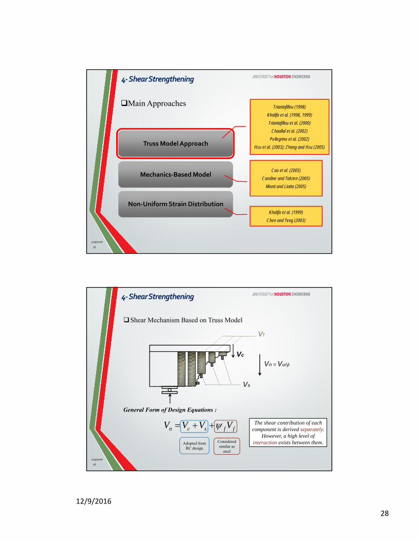
54
Parameters Influencing the Behavior
Wrapping Schemes
0
20
40
60
80
100
120
140
160
180
200
Side Bonding U-Wrap Completewrapping
Nu
mb
er o
f T
est
Sp
ecim
ens
FRP Wrapping Schemes
Other
FRP Rupture
FRP Debonding81%
65%
55%
4‐ShearStrengthening
12/9/2016
12/9/2016
28
55
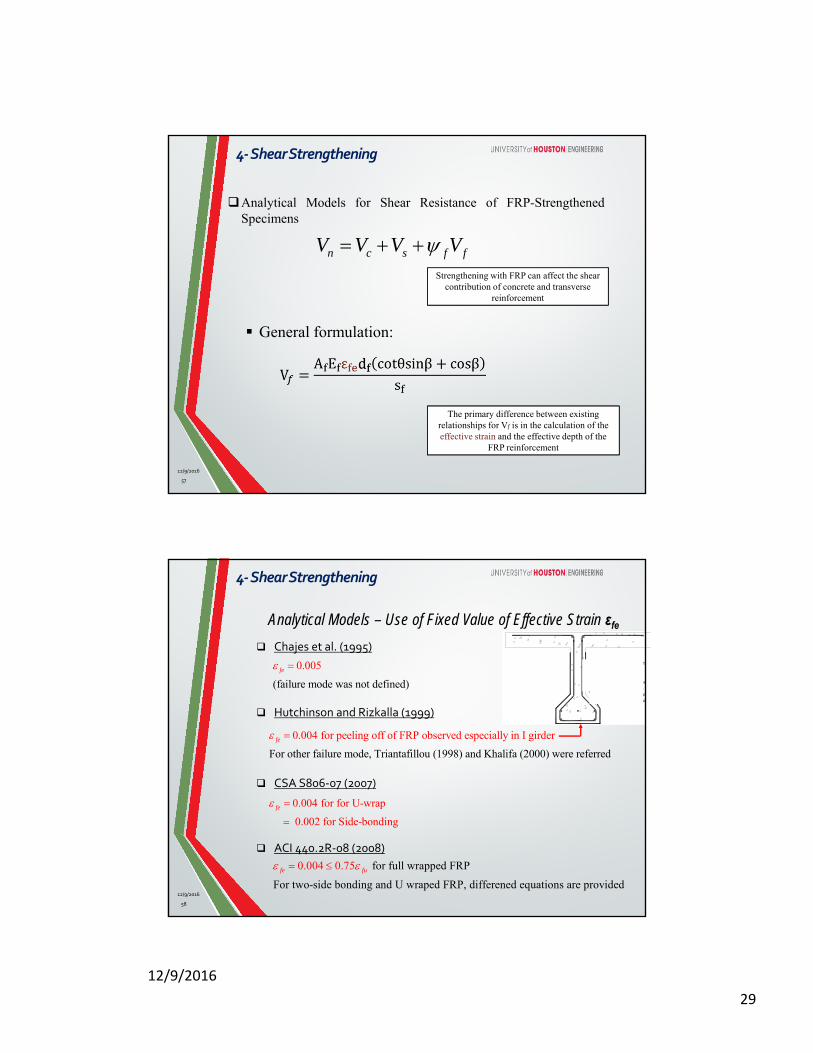
Truss Model Approach
Non‐Uniform Strain Distribution
Mechanics‐Based Model
Triantafillou (1998)
Khalifa et al. (1998, 1999)
Triantafillou et al. (2000)
Chaallal et al. (2002)
Pellegrino et al. (2002)
Hsu et al. (2003); Zhang and Hsu (2005)
Cao et al. (2005)
Caroline and Talsten (2005)
Monti and Liotta (2005)
Khalifa et al. (1999)
Chen and Teng (2003)
Main Approaches
4‐ShearStrengthening
12/9/2016
56
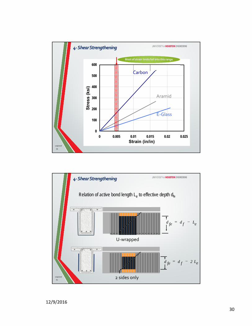
Shear Mechanism Based on Truss Model
The shear contribution of each component is derived separately.
However, a high level of interaction exists between them.
General Form of Design Equations :
Vs
Vf
Vc
n c s f fV V V V
Adopted from RC design
Considered similar as
steel
Vn = Vu/
4‐ShearStrengthening
12/9/2016
12/9/2016
29
57
Analytical Models for Shear Resistance of FRP-StrengthenedSpecimens
General formulation:
n c s f fV V V V Strengthening with FRP can affect the shear
contribution of concrete and transverse reinforcement
The primary difference between existing relationships for Vf is in the calculation of the effective strain and the effective depth of the
FRP reinforcement
4‐ShearStrengthening
12/9/2016
Analytical Models – Use of Fixed Value of Effective Strain εfe
Chajes et al. (1995)
Hutchinson and Rizkalla (1999)
CSA S806‐07 (2007)
(failure mode was not
0
d
.0
ef n )
05
i ed
fe
For other fail
0.004 for
ure mode,
peeling off of FRP o
Triantafillou (1998)
bserved especia
and Khalifa (2
ll
00
y in I girder
0) were referred
fe
FRP debondingdue to shear peeling
Outward force resuthe tensile forces invertical and diagonshear reinforcemen
0.004 for for U-wrap
0.002 for Side-bonding
fe
ACI 440.2R‐08 (2008)
for full wrapped FRP
For two-side bonding and U wraped FRP, differened equati
0.004
ons a
0.75
re provided
fe fu
58
4‐ShearStrengthening
12/9/2016
12/9/2016
30
59
Review Of Shear Strengthening With FRP
0
100
200
300
400
500
600
0 0.005 0.01 0.015 0.02 0.025
Strain (in/in)
Str
ess
(ksi
)
0
100
200
300
400
500
600
0 0.005 0.01 0.015 0.02 0.025
Strain (in/in)
Str
ess
(ksi
)
Carbon
Aramid
E‐Glass
Most of strain limits fall into this range Most of strain limits fall into this range
4‐ShearStrengthening
12/9/2016
Relation of active bond length Le to effective depth dfe
2 sides only
U‐wrapped
effe L2dd
effe Ldd
4‐ShearStrengthening
60
12/9/2016
12/9/2016
31
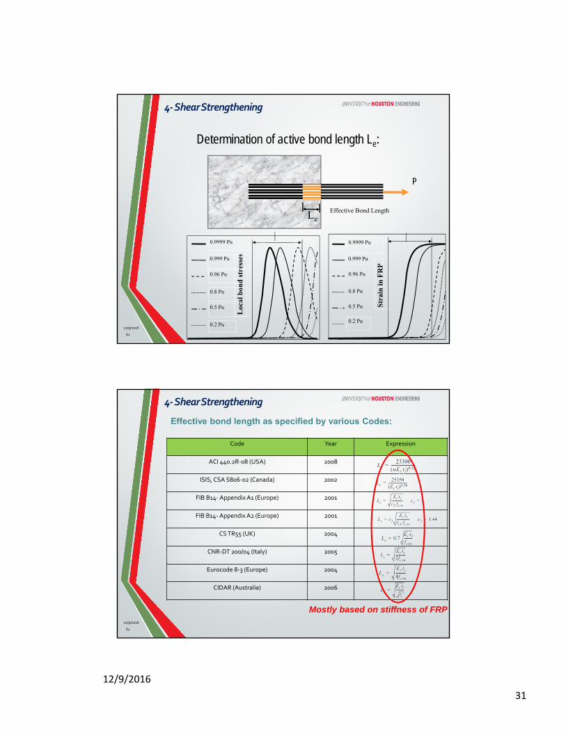
Determination of active bond length Le:
Loc
al b
ond
str
esse
s 0.9999 Pu
0.999 Pu
0.96 Pu
0.8 Pu
0.5 Pu
0.2 Pu
Effective Bond Length
Str
ain
in F
RP
0.9999 Pu
0.999 Pu
0.96 Pu
0.8 Pu
0.5 Pu
0.2 Pu
P
Le
4‐ShearStrengthening
12/9/2016
61
Code Year Expression
ACI 440.2R‐08 (USA) 2008
ISIS, CSA S806‐02 (Canada) 2002
FIB B14‐Appendix A1 (Europe) 2001
FIB B14‐Appendix A2 (Europe) 2001
CS TR55 (UK) 2004
CNR‐DT 200/04 (Italy) 2005
Eurocode 8‐3 (Europe) 2004
CIDAR (Australia) 2006
Effective bond length as specified by various Codes:
Mostly based on stiffness of FRP
4‐ShearStrengthening
62
12/9/2016
12/9/2016
32
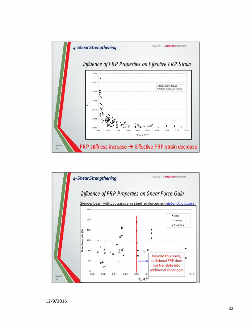
Influence of FRP Properties on Effective FRP Strain
0.000
0.008
0.016
0.024
0.032
0.040
0.048
0.00 0.02 0.04 0.06 0.08 0.10 0.12 0.14 0.16 0.18
Debonding failureOther modes of failure
E f f /f c2/3
f, e
FRP stiffness increase Effective FRP strain decrease
4‐ShearStrengthening
12/9/2016
63
Influence of FRP Properties on Shear Force Gain
Slender beam without transverse steel reinforcement‐debonding failure
0
40
80
120
160
200
240
0.00 0.02 0.04 0.06 0.08 0.10 0.12 0.14 0.16 0.18
Sides
U-Wrap
Total-Wrap
Eff/fc2/3
Sh
ear
forc
e g
ain
(%
)
Beyond this point, additional FRP does not translate into
additional shear gain
4‐ShearStrengthening
12/9/2016
64
12/9/2016
33
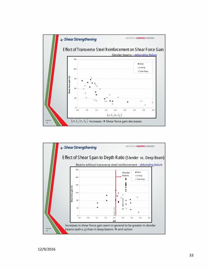
Effect of Transverse Steel Reinforcement on Shear Force Gain
0
30
60
90
120
150
0.0 0.5 1.0 1.5 2.0 2.5 3.0 3.5 4.0
Sides
U-Wrap
Total-Wrap
fs,ts,t/ff,ef
Sh
ear
forc
e g
ain
(%
)
v y f fef f
Slender beams – debonding failure
Increases Shear force gain decreases v y f fef f
4‐ShearStrengthening
12/9/2016
65
Effect of Shear Span to Depth Ratio (Slender vs. Deep Beam)Beams without transverse steel reinforcement – debonding failure
Increases in shear force gain seem in general to be greater in slender beams (a/d>2.5) than in deep beams arch action
0
40
80
120
160
200
240
0.0 0.6 1.2 1.8 2.4 3.0 3.6 4.2 4.8
Sides
U-Wrap
Total-Wrap
a/d
Sh
ear
fo
rce
gai
n (
%)
Slender beams
4‐ShearStrengthening
12/9/2016
66
12/9/2016
34
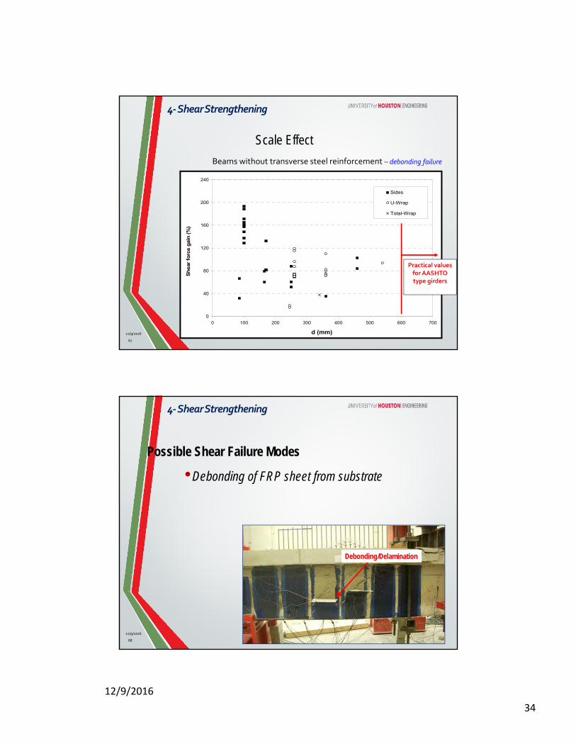
Beams without transverse steel reinforcement – debonding failure
Scale Effect
0
40
80
120
160
200
240
0 100 200 300 400 500 600 700
Sides
U-Wrap
Total-Wrap
d (mm)
Sh
ear
fo
rce g
ain
(%
)
Practical values for AASHTO type girders
4‐ShearStrengthening
12/9/2016
67
•Debonding of FRP sheet from substrate
Possible Shear Failure Modes
Debonding/Delamination
68
4‐ShearStrengthening
12/9/2016
12/9/2016
35
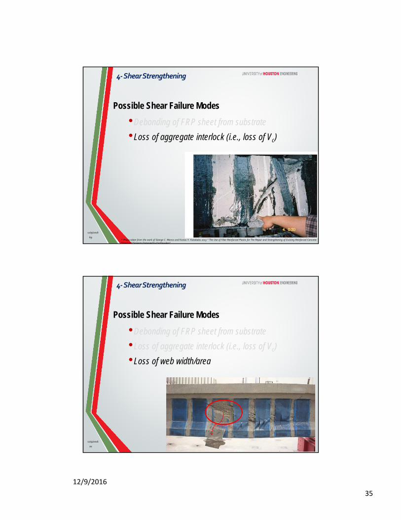
•Debonding of FRP sheet from substrate
•Loss of aggregate interlock (i.e., loss of Vc)
* Photo taken from the work of George C. Manos and Kostas V. Katakalos 2013 ” The Use of Fiber Reinforced Plastic for The Repair and Strengthening of Existing Reinforced ConcreteStructural Elements Damaged by Earthquakes”
69
Possible Shear Failure Modes
4‐ShearStrengthening
12/9/2016
•Debonding of FRP sheet from substrate
•Loss of aggregate interlock (i.e., loss of Vc)
•Loss of web width/area
70
Possible Shear Failure Modes
4‐ShearStrengthening
12/9/2016
12/9/2016
36
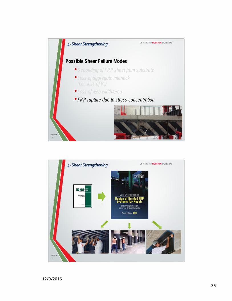
•Debonding of FRP sheet from substrate
•Loss of aggregate interlock (i.e., loss of Vc)
•Loss of web width/area
•FRP rupture due to stress concentration
71
Possible Shear Failure Modes
4‐ShearStrengthening
12/9/2016
72
4‐ShearStrengthening
12/9/2016
12/9/2016
37
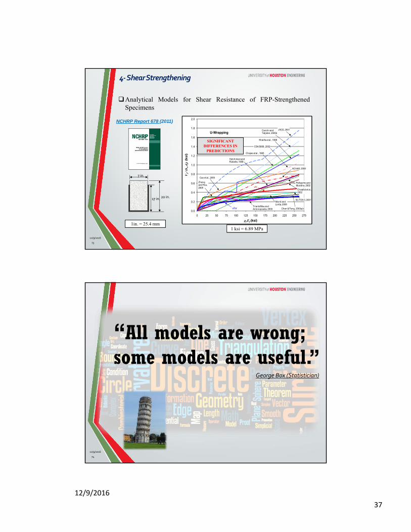
73
Analytical Models for Shear Resistance of FRP-StrengthenedSpecimens
0.0
0.2
0.4
0.6
0.8
1.0
1.2
1.4
1.6
1.8
2.0
0 25 50 75 100 125 150 175 200 225 250 275
Vf / (
b w d
f)(k
si)
ρf Ef (ksi)
U-Wrapping
Chaallal et al., 2002
Hutchinson and Rizkalla, 1999
Carolin and Taljsten, 2005b
Chajes et al., 1995
Khalifa et al., 1998
ACI 440, 2008
Pellegrino and Modena, 2002
Cao et al., 2005
Triantafillou and Antonopoulos, 2000 Chen & Teng, 2003a,b
fib-TG9.3, 2001
CSA S806, 2002
Zhang and Hsu, 2005
vfnr
vf r
JSCE, 2001
Monti and Liotta, 2005
17 in.
7 in.
20 in.
SIGNIFICANT DIFFERENCES IN
PREDICTIONS
NCHRP Report 678 (2011)
1in. = 25.4 mm1 ksi = 6.89 MPa
4‐ShearStrengthening
12/9/2016
“All models are wrong; some models are useful.”
George Box (Statistician)
74
12/9/2016

12/9/2016
38
75
Element Behavior as Part of a Complete Structure
5‐SoftenedMembraneModel
12/9/2016
High-Rise Building Core(Shanghai Tower, 2,073 ft)
5‐SoftenedMembraneModel
76
12/9/2016
12/9/2016
39
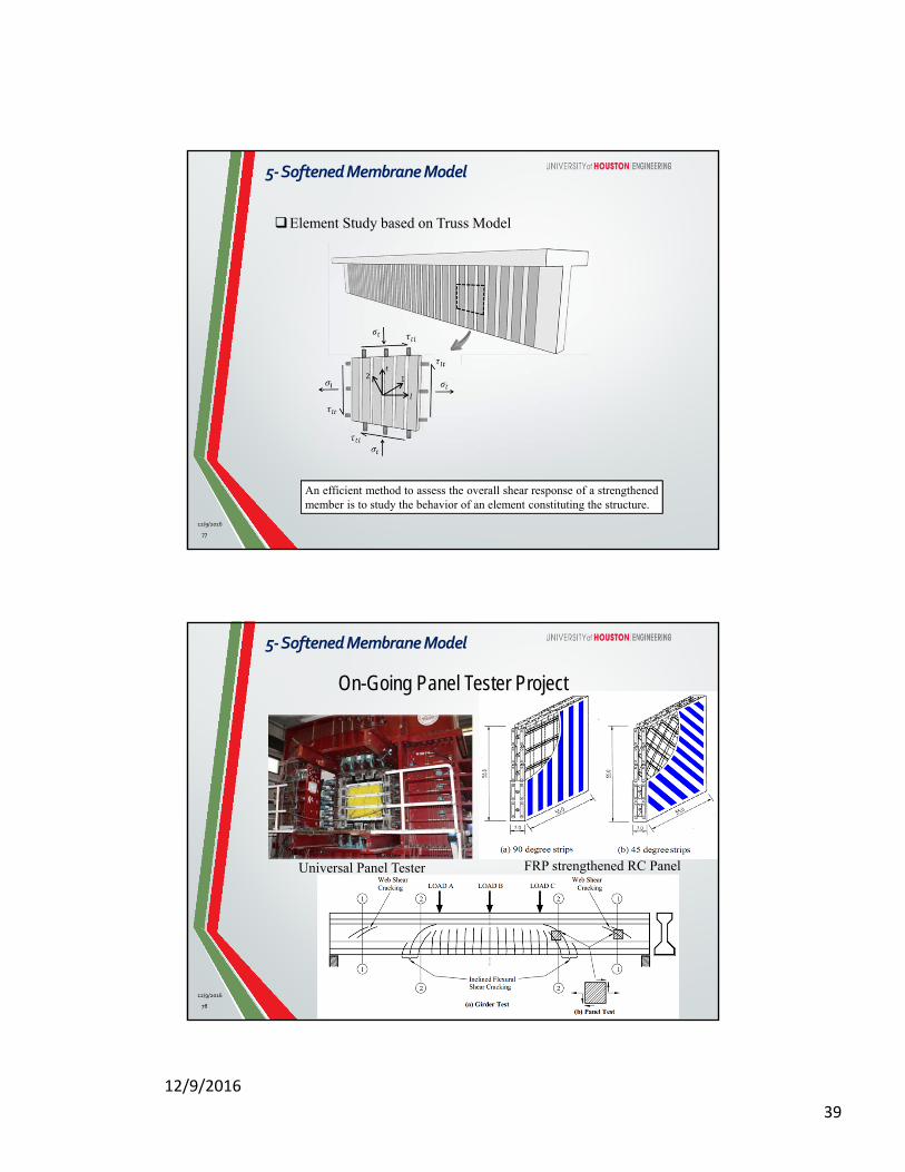
77
An efficient method to assess the overall shear response of a strengthenedmember is to study the behavior of an element constituting the structure.
Element Study based on Truss Model
5‐SoftenedMembraneModel
12/9/2016
Universal Panel Tester FRP strengthened RC Panel
On-Going Panel Tester Project
5‐SoftenedMembraneModel
12/9/2016
78
12/9/2016
40
79
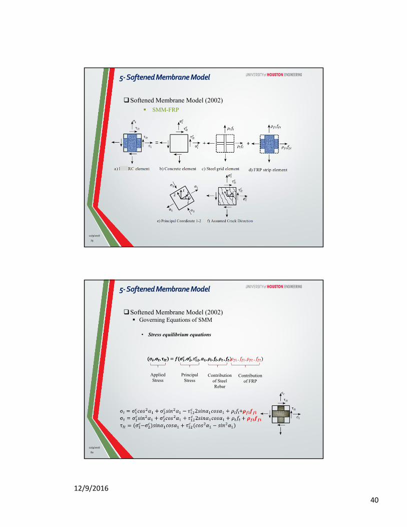
Softened Membrane Model (2002) SMM-FRP
5‐SoftenedMembraneModel
12/9/2016
80
Softened Membrane Model (2002) Governing Equations of SMM
• Stress equilibrium equations
Applied Stress
Principal Stress
Contribution of Steel Rebar
Contribution of FRP
5‐SoftenedMembraneModel
12/9/2016
12/9/2016
41
81
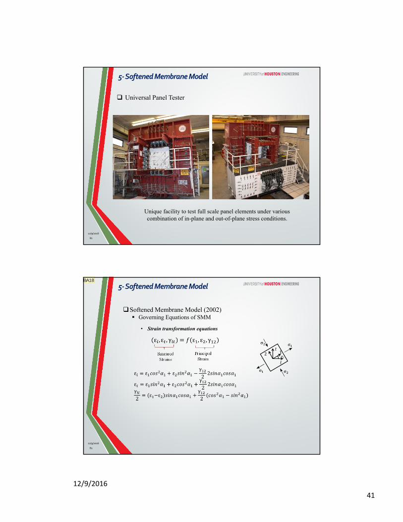
Universal Panel Tester
Unique facility to test full scale panel elements under various combination of in-plane and out-of-plane stress conditions.
5‐SoftenedMembraneModel
12/9/2016
82
Softened Membrane Model (2002) Governing Equations of SMM
• Strain transformation equations
Smeared Strains
Principal Strain
5‐SoftenedMembraneModel
12/9/2016
BA18
12/9/2016
42
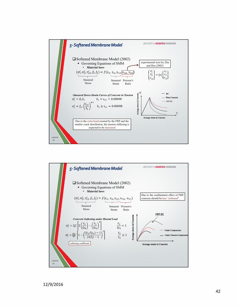
Softened Membrane Model (2002) Governing Equations of SMM
• Material laws
-Smeared Stress-Strain Curves of Concrete in Tension
83
Smeared Stress
Smeared Strain
Poisson’s Ratio
experimental tests by Zhu and Hsu (2002)
Ave
rage
str
ess
in C
oncr
ete
Average strain in Concrete
RC
Plain Concrete
Ave
rage
str
ess
in C
oncr
ete
Average strain in Concrete
RC
Plain Concrete
FRP RC
Due to the extra bond created by the FRP and the smaller crack distribution, the tension stiffening is
expected to be increased
5‐SoftenedMembraneModel
12/9/2016
84
softening coefficient
Ave
rage
str
ess
in C
oncr
ete
Average strain in Concrete
Under Compression
Under Tension-Compression
Ave
rage
str
ess
in C
oncr
ete
Average strain in Concrete
Under Compression
Under Tension-Compression
FRP RC
Due to the confinement effect of FRP,concrete should be less “softened”
Softened Membrane Model (2002) Governing Equations of SMM
• Material laws
-Concrete Softening under Biaxial Load
Smeared Stress
Smeared Strain
Poisson’s Ratio
5‐SoftenedMembraneModel
12/9/2016
12/9/2016
43
85
Softened Membrane Model (2002) Governing Equations of SMM
• Material laws
-Smeared Stress-Strain Curves of Steel in Tension
Ave
rage
str
ess
in s
teel
Average strain in steel
Bare Rebar
Rebar in RC
Rebar in FRP RC
The apparent yielding point will increasedue to the decrease in crack width becauseof FRP.
Ave
rage
str
ess
in s
teel
Average strain in steel
Bare Rebar
Rebar in RC
Apparent Yielding Point
Smeared Stress
Smeared Strain
Poisson’s Ratio
5‐SoftenedMembraneModel
12/9/2016
86
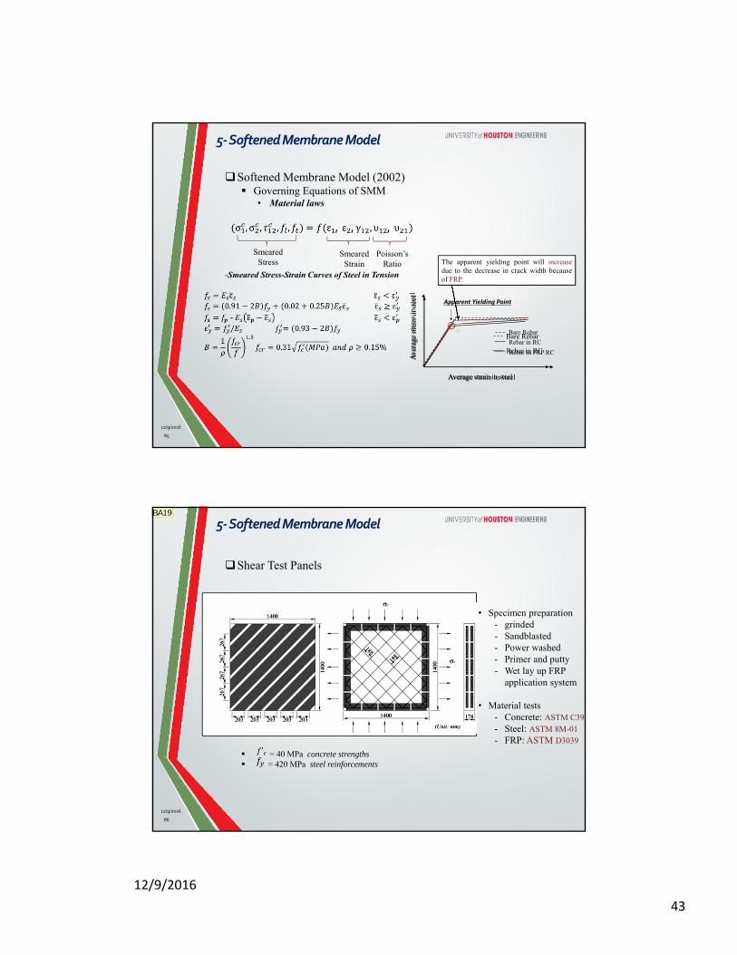
Shear Test Panels
= 40 MPa concrete strengths = 420 MPa steel reinforcements
• Specimen preparation- grinded- Sandblasted- Power washed- Primer and putty- Wet lay up FRP
application system
• Material tests- Concrete: ASTM C39- Steel: ASTM 8M-01 - FRP: ASTM D3039
5‐SoftenedMembraneModel
12/9/2016
BA19

12/9/2016
44
87
Specimen #
Name (%) (%) (%) Wrapping Scheme Anchorage method
1 REF_P4 0.76 0.76 - - - 2 REF_P3 0.76 0.43 - - - 3 P4_040_SB 0.76 0.76 0.87 Side Bonding - 4 P4_040_FA 0.76 0.76 0.87 U-Wrap CFRP anchor 5 P4_025_FW 0.76 0.76 0.54 Fully Wrap - 6 P4_040_FW 0.76 0.76 0.87 Fully Wrap - 7 P4_025_FA 0.76 0.76 0.54 U-Wrap CFRP anchor 8 P3_040_FW 0.76 0.43 0.87 Fully Wrap - 9 P3_025_FW 0.76 0.43 0.54 Fully Wrap -
10 P4_080_FW 0.76 0.76 1.74 Fully Wrap -
Shear Test Matrix
5‐SoftenedMembraneModel
12/9/2016
88
-0.1
0
0.1
0.2
0.3
0.4
0.5
0 0.002 0.004 0.006 0.008 0.01
21
Average Tensile Strain (in/in)
PR-025PR-040PR-080Model for RC
0
1
2
3
4
0 0.002 0.004 0.006 0.008 0.01
12
Average Tensile Strain (in/in)
PR-025PR-040PR-080Model for RC
The proposed equation for calculating Hsu/Zhu ratio for RC element significantly overestimated the Poisson effect for the FRP RC element.With the increase of FRP stiffness, the Poisson effect becomes less significant.
5‐SoftenedMembraneModel
12/9/2016
12/9/2016
45
89
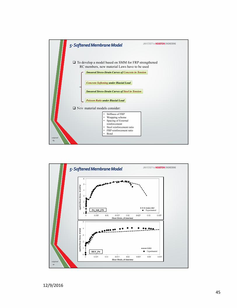
To develop a model based on SMM for FRP strengthenedRC members, new material Laws have to be used
New material models consider:
Smeared Stress-Strain Curves of Concrete in Tension
Concrete Softening under Biaxial Load
Smeared Stress-Strain Curves of Steel in Tension
Poisson Ratio under Biaxial Load
• Stiffness of FRP• Wrapping scheme• Spacing of External
reinforcement• Steel reinforcement ratio• FRP reinforcement ratio• Bond
5‐SoftenedMembraneModel
12/9/2016
90
5‐SoftenedMembraneModel
12/9/2016
12/9/2016
46
91
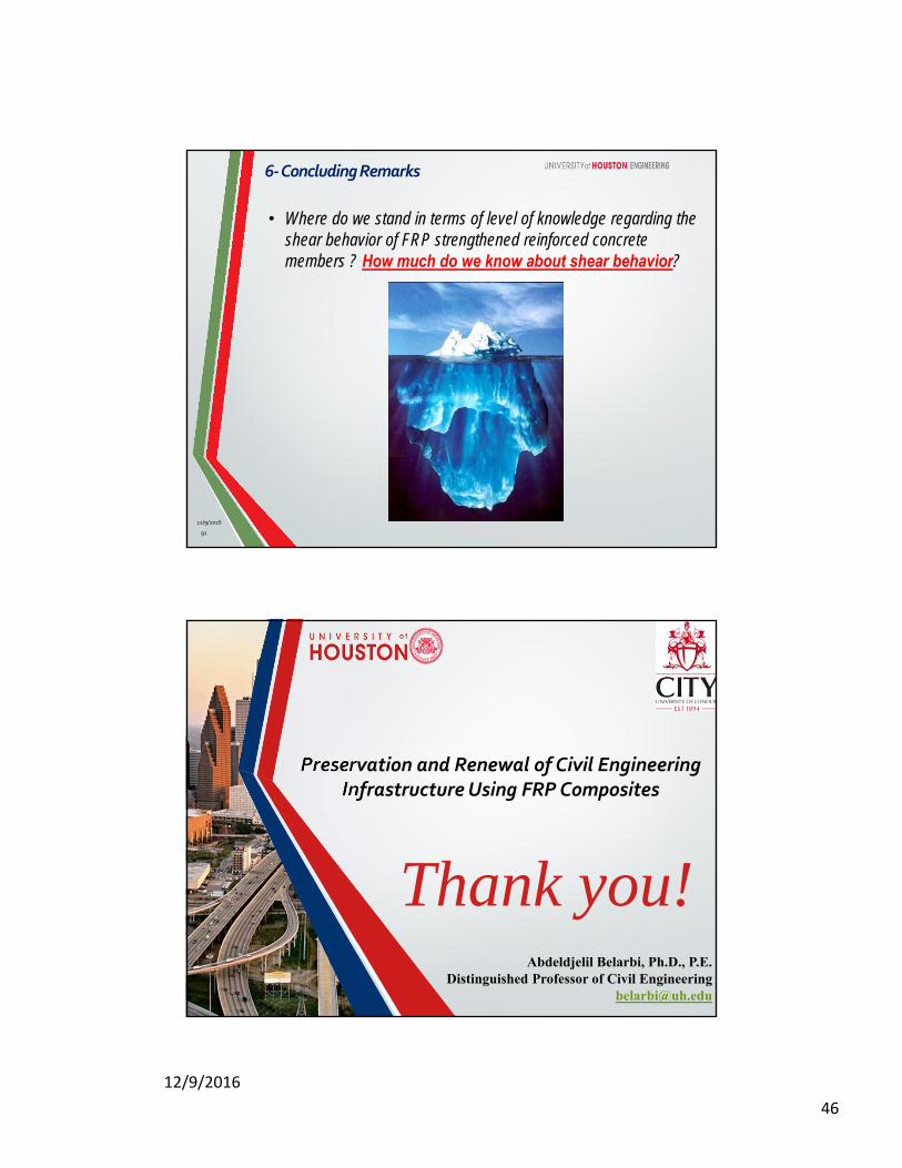
• Where do we stand in terms of level of knowledge regarding the shear behavior of FRP strengthened reinforced concrete members ? How much do we know about shear behavior?
6‐ConcludingRemarks
12/9/2016
Preservation and Renewal of Civil Engineering Infrastructure Using FRP Composites
Thank you!Abdeldjelil Belarbi, Ph.D., P.E.
Distinguished Professor of Civil [email protected]