Embed Size (px)
Citation preview

2001-02 AAPG Distinguished LectureFunded by the AAPG Foundation
through the J. Ben Carsey Memorial Endowment
Outcrop/Behind Outcrop Characterization of Deepwater (Turbidite) Petroleum Reservoir
Analogs: Why and How
Roger M. SlattUniversity of OklahomaNorman, Oklahoma

© 2001 The American Association of Petroleum Geologists and Roger M. Slatt
No slides, figures, text or other matter contained herein may be reproduced without the written permission of both the American
Association of Petroleum Geologists and Roger M. Slatt

ENGINEERING DEFINITION: Drilling a well offshore intoa basin fill in present-day water depths greater than 500m (1500ft) above the mud line (ocean floor).

0
10
20
30
40
5019
78
1980
1982
1984
1986
1988 19
9019
92
1994
1996
1998
2000
Year
BB
OE
Cumulative GasCumulative Oil/Cond.
Oil
Gas
Deepwater (>500m) discovered reserves
Source:Source:VariousVarious
< 25% Developed or In Development
Cumulative BBOE in Ultra-Deep Water (>2000m)
UDW
Portion of BBOE Developed or under development
Developed
7 BB
OE
per y
ear
Discoveriesmainly from:Gulf of Mexico,offshore W.Africa and Brazil, N. Sea,SW shelfAustralia, SEAsia

Mid-Norway
Faroes White ZoneWoS
NWS & ZOCA
US GoMTaumalipas & Campeche
Morocco
Brazil
Scotian &Jeanne D’Arc
Trinidad
Sakhalin
NigeriaEq. GuineaGabonCongoAngola
Mozambique
S. Africa
Tanzania
So. CaspianItaly
Egypt
NW & SE BorneoNW & SE Borneo
2,0 0,9
1,82.72.0
Areas of Prospective Deepwater and Ultra-Deepwater Basins
10,9
0,9
12
0,5
12,413
6,8
0,1
7
3,0
0,6
3.6
E. India
Taranaki
Recoverable Resources in BBOE (green= oil, red = gas)
Total Discovered57 BBOE37 BBO + 120 TCF
Data Sources: Pettingill (1999), various othersData Sources: Pettingill (1999), various others
Deepwater Discovered Reserves>500m water depthas of Sept. 2001
8,6
3,0
10
4

SIX RESERVOIR TYPES
Sp
GEOLOGIC DEFINITION: Clastic sediments transported beyond the shelfedge into deep water by sediment gravity flow processes and deposited onthe continental slope and in the basin. They are later buried and become partof a basin fill: Engineering and geologic ‘deep water’ are usually the same.

(Roberts and Compani, 1996)
TYPE III
SUBMARINE CHANNEL SYSTEM
OVERBANK
CHANNEL
AGGRADING CHANNEL-LEVEE
COMPLEX
OVERBANKSLUMP
CHANNEL PROXIMAL LEVEE
LEVEE
Distal levee or
Splay
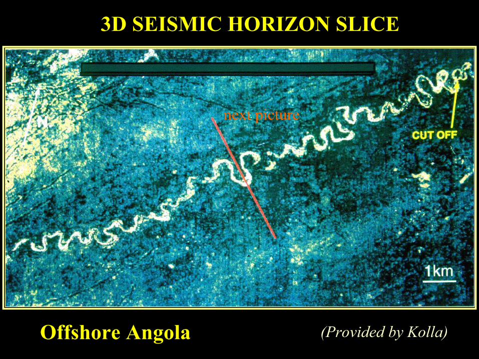
(Provided by Kolla)
3D SEISMIC HORIZON SLICE
Offshore Angola
next picture

Kolla et al., 2001Black = positive seismic reflectionPurple = negative seismic reflection
3D Seismic line, offshore Angola

Kolla et al., 2001Black = positive seismic reflectionPurple = negative seismic reflection
3D Seismic line, offshore Angola
Discovery Well

• HOW BIG IS THE RESERVOIR?
• HOW WILL THIS RESERVOIR STYLE PERFORM?
• HOW WIDELY MUST WE SPACE OUR EXPENSIVE DEVELOPMENT WELLS?
• SHOULD WE DRILL A VERTICAL, SLANT, OR HORIZONTAL WELL??
• HOW CAN WE FAST-TRACK DEVELOPMENT OF THIS RESERVOIR?
• WHAT WENT WRONG?
APPRAISAL & DEVELOPMENTAPPRAISAL & DEVELOPMENT

ConHOW CAN OUTCROPS HELP ANSWER
THOSE TOUGH QUESTIONS??
BUILDING A SCALED GEOLOGIC MODEL FROM OUTCROPS:
•Sheet Sandstone Reservoirs
•Leveed Channel Sandstone Reservoirs
Lets study the Cretacous Lewis Shale in Wyoming!!

TOOLS AND TECHNIQUES FOR TOOLS AND TECHNIQUES FOR OUTCROP CHARACTERIZATONOUTCROP CHARACTERIZATON
STANDARD RECENT ADDITIONS
•Brunton Compass •Photomosaics on Workstation•Hand Lens •Outcrop gamma-ray/sonic logs•Jacobs Staff •Behind-outcrop logging/coring•Tape Measure •Ground Penetrating Radar (GPR)•Rock Hammer •Global Positioning System (GPS)•Camera •Ultra-shallow seismic behind
outcrop•Outcrop Minipermeameter•3D Imaging

S1 and S2 are continuous Lewis sheet sandstonesCC is Lewis leveed channel complex on Spine IF is shallow marine Fox Hills
Spine IWest
North
12
Cretaceous Lewis Shale, Wyoming“Bashful outcrops”

S1 and S2 are continuous Lewis sheet sandstonesCC is Lewis leveed channel complex on Spine IF is shallow marine Fox Hills
Spine IWest
North
Cretaceous Lewis Shale, Wyoming

Lithofacies A
(Witton, 1999)
Sheet Sandstones
Sheet Sandstones:Laterally continuousfor miles: i.e. goodpotential reservoir facies; individualsandstone intervalsare separated by shales.

S1 and S2 are continuous Lewis sheet sandstonesCC is Lewis leveed channel complex on Spine IF is shallow marine Fox Hills
Spine IWest
North
Cretaceous Lewis Shale, Wyoming
Laterally continuous sandstones
Laterally continuous shales in between

S1 and S2 are continuous Lewis sheet sandstonesCC is Lewis leveed channel complex on Spine IF is shallow marine Fox Hills
Spine IWest
North
Cretaceous Lewis Shale, Wyoming

Channel-fill #1Sandstone
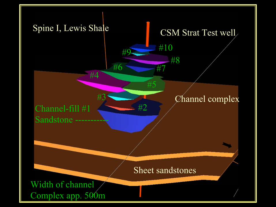
10 Channel-fill sandstones, each separated by shale/mudstone breaks:i.e. discontinuousreservoirs; not so easy to develop as reservoirs
#2 #3 #4 #5 #6
Well-------
Spine I(yellow line is app. 450m on ground; 120m of strat. section)

Behind-outcrop drilling for logs and core

Gamma Ray CoreGR
Bulk DensitySonic Dt
Neutron PorosityCore Porosity
CSM StratTest #61Core andLog Data
Outcrop
Subcrop
Where’s the10 sands??

Channel-fill #1Sandstone
Where did the Channel-fill #1 Sandstone go?? Meander loop ofsinuous channel??
#2 #3 #4 #5 #6
Well-------

Channel-fill #1Sandstone
Where did the Channel-fill #1 Sandstone go?? Meander loop ofsinuous channel??
#2 #3 #4 #5 #6
Well-------

Thin-bedded,extra-channelor levee facies
Rain gulley

Sheet sandstones
Channel complex
Spine I, Lewis Shale CSM Strat Test well
Channel-fill #1Sandstone -----------
#2#3
#4#5
#6 #7#8
#9 #10
Width of channelComplex app. 500m
Sinuosity notshown in model
Thin levee bedsnot shown inmodel

Channel-fill #1Sandstone
Laterally discontinuous channel-fill sandstone
(150m across in outcrop)

Massive sands w/ fluid escape structures
X-bedded sands
Red = shale clast cong. Brown = sandy debrites
Channel-fill #1 Sandstone; oblique view across channel-fill

Cross-bedded sandstone

Interbedded turbidites and debrites
Shale clast conglomerate(debrite)
Turbidite

Channel-fill #1Sandstone
Laterally discontinuous channel-fill sandstone
(150m across in outcrop)

Ground-penetrating radar (GPR) line across channel marginshowing sharp channel boundary and internal channel-slumpfeatures (Young et al,, 1999)
Margin of Channel Sandstone #1
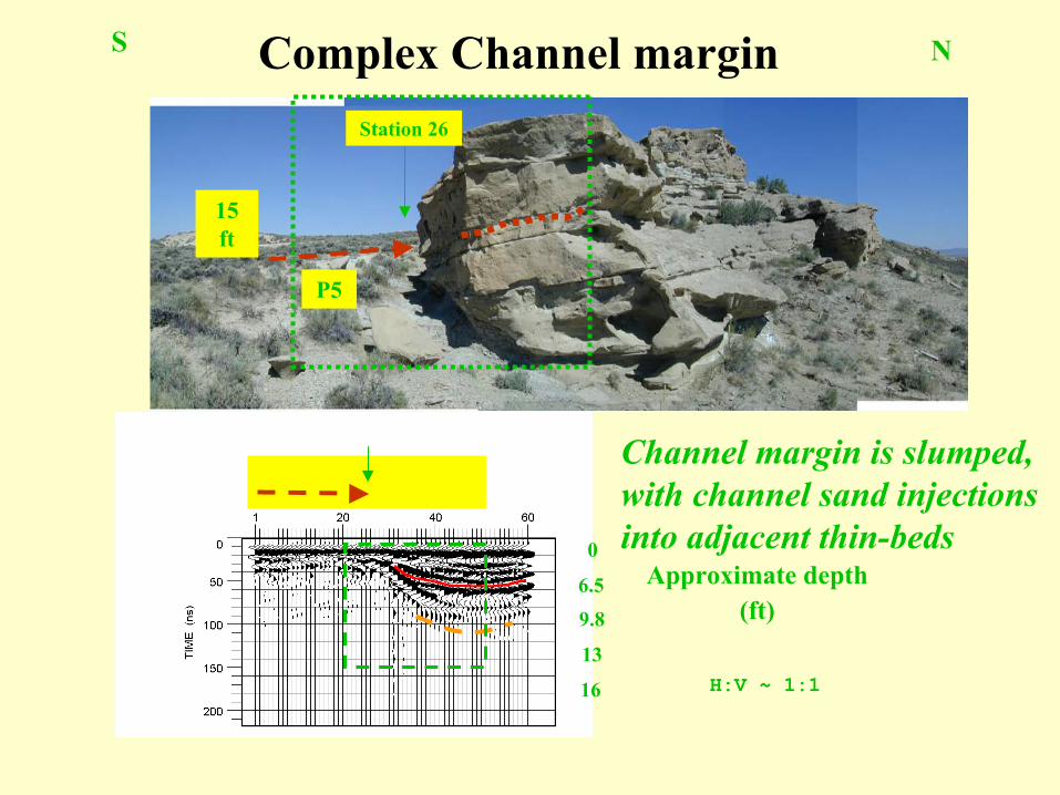
P5
15 ft
Station 26
Approximate depth(ft)
H:V ~ 1:1
0
6.5
9.8
13
16
S N
Channel margin is slumped,with channel sand injectionsinto adjacent thin-beds
Complex Channel margin

Channel Sandstone
Thin bedded Sandstones/Mudstones
Slumpedbeds

Channel Sandstone
Thin bedded Sandstones/Mudstones
Slumpedbeds
No communicationacross slumped zonein reservoir analogs
Sheet sandstones
Channel complex
Spine I, Lewis Shale CSM Strat Test well
Channel-fill #1Sandstone -----------
#2#3
#4#5
#6 #7#8
#9 #10
Width of channelComplex app. 500m

Sheet sandstones
Channel complex
Spine I, Lewis Shale CSM Strat Test well
Channel-fill #1Sandstone -----------
#2#3
#4#5
#6 #7#8
#9 #10
Width of channelComplex app. 500m

Sheet sandstones
Channel complex
Spine I, Lewis Shale CSM Strat Test well
Channel-fill #1Sandstone -----------
#2#3
#4#5
#6 #7#8
#9 #10
Width of channelComplex app. 500m
Complex channelmargin

Kolla et al., 2001Black = positive seismic reflectionPurple = negative seismic reflection
3D Seismic line, offshore Angola
Multiple channel sandstones separatedby mudstones
Sheet Sandstones separated by mudstones

Kolla et al., 2001Black = positive seismic reflectionPurple = negative seismic reflection
3D Seismic line, offshore Angola
Discovery Well

Kolla et al., 2001Black = positive seismic reflectionPurple = negative seismic reflection
Well

ConHOW CAN OUTCROPS HELP ANSWERTHOSE TOUGH QUESTIONS??
BUILDING A SCALED GEOLOGIC MODEL FROM OUTCROPS:
•Thin-bedded levee reservoirs
Lets study the Miocene Mt. Messenger Formationin New Zealand!!

(Roberts and Compani, 1996)
TYPE III
SUBMARINE CHANNEL SYSTEM
OVERBANK
CHANNEL
AGGRADING CHANNEL-LEVEE
COMPLEX
OVERBANKSLUMP
CHANNEL PROXIMAL LEVEE
LEVEE
Distal levee or
Splay

Miocene Mt. Messenger Formation, Taranaki Basin, New Zealand: Cliff is 250m high and several km long
PHOTOMOSAICS FROM HELICOPTER; WELLS; CORES; LOGS; HIGH-RESOLUTION SHALLOW SEISMIC; MEASURED SECTIONS
TwoWells
H.R.Seismic

Depositional interval or bed scale

C
P--D
C = channel fill (upward dip decrease); P = proximal levee (high & variable angle dips); D = distal levee;
Pleistocene-----------(brown)

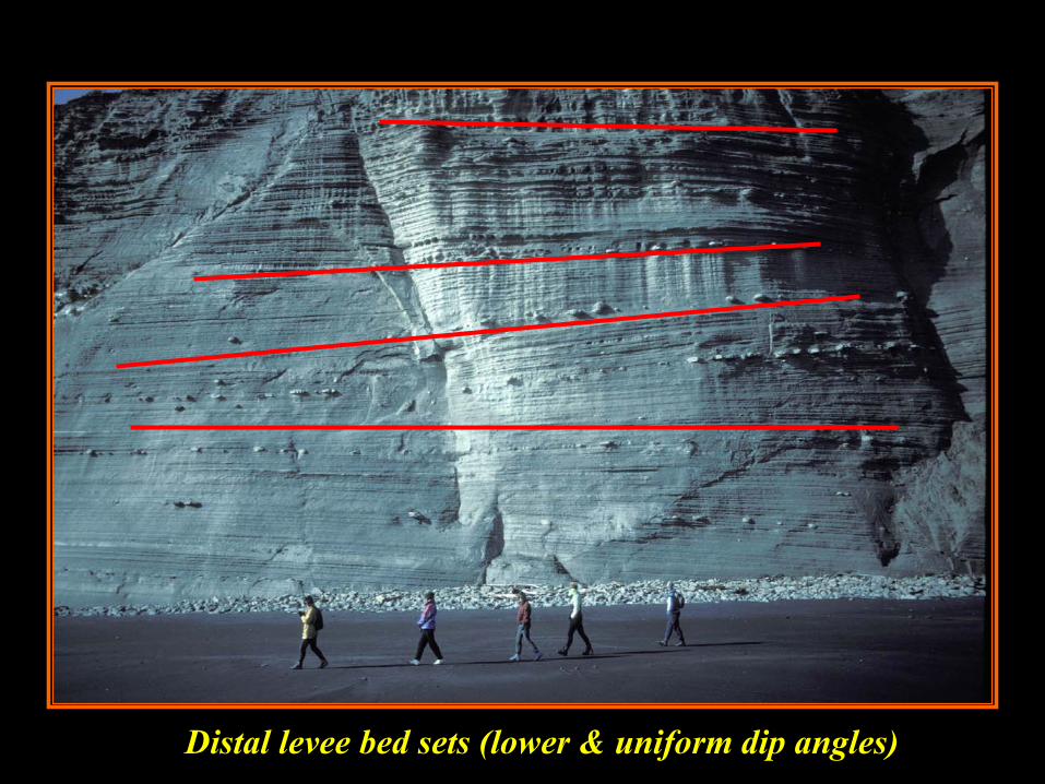
Distal levee bed sets (lower & uniform dip angles)

(Slatt et al., 1998)
Behind-outcrop dipmeterlogs (bySchlumber-ger)
Channelfill
Prox-imallevee
Distal levee/overbank


Kolla et al., 2001Black = positive seismic reflectionPurple = negative seismic reflection
3D Seismic line, offshore Angola
Multiple channel sandstones separatedby mudstones
Sheet Sandstones separated by mudstones
Levee beds Levee beds

Kolla et al., 2001Black = positive seismic reflectionPurple = negative seismic reflection
Well

3363 ft
J sand L sand
M sand
Tertiary Cretaceous Unconformity
West East
N sand
4.0 s
4.5 s
Ram/Powell Field
(Clemenceau et al., 2000)
L Sand, Ram/Powell Field, Gulf of Mexico: comprises channel,proximal, & distal levee facies.

proximal levee distal levee
west east
datum base of sand
channel
100
ftwet
low resistivity gas pay 2 ohms
(Clemenceau et al, 2000)
Ram Powell ‘L’ Sand

proximal levee distal levee
west east
datum base of sand
channel
100
ftwet
low resistivity gas pay 2 ohms
(Clemenceau et al, 2000)
Ram Powell ‘L’ Sand
Inferred complexchannel margin

proximal levee distal levee
west east
datum base of sand
channel
100
ftwet
low resistivity gas pay 2 ohms
(Clemenceau et al, 2000)
Ram Powell ‘L’ Sand
Inferred complexchannel margin

(Clemenceau et al., 2000)

3 miles
A-1(horizontal)
A
D
B
C
E GOC
L-1 LKOChannel
Seismic line Fig. 5
proximal levee
N
Amplitude
high
low
wet wellA5A8st1A8st2A17957-1st2well test
ABCDE
distal levee-overbank
100 ft contour interval(Clemenceau et al, 2000)Ram Powell ‘L’ Sand
Drilling Strategy: Horizontal well in proximal levee beds, parallel to channel:“Well performance exceeded expectations with a peak flow rate of 105mmcfgd and 9600 bopd”

WHAT IF YOU DON’T HAVEWHAT IF YOU DON’T HAVE
SEISMIC????SEISMIC????BOREHOLE IMAGE LOGS WILL ALLOW YOU TO DIFFERENTIATE FACIES FOR VOLUMETRICS AND DRILLING STRATEGY (i.e. conventionalwell logs won’t differentiate facies with any degree of certainty)
-Wellbore and behind-outcrop borehole image logs (STARTM and FMItm) verify this in Lewis Shaleand Mt. Messenger!!
TM Baker-HughestmSchlumberger

(Witton, 2000)
Debrites andTurbidites =
Channel -fillsandstones
BoreholeImage Log, Lewis Sh.

(Witton, 2000)
Turbiditesonly =
SheetSandstones
BoreholeImageLog, Lewis Sh.

Levee bedsfrom Mt.MessengerFm. NewZealand


Well
Well

Well
Well

ConYET ANOTHER USE OF OUTCROPS
•3D GEOLOGIC MODELING FOR VISUALIZATION, RESERVOIR PERFORMANCE PREDICTION & WELL PLACEMENT
Lets study the Penn. Jackfork Group in Arkansas!!
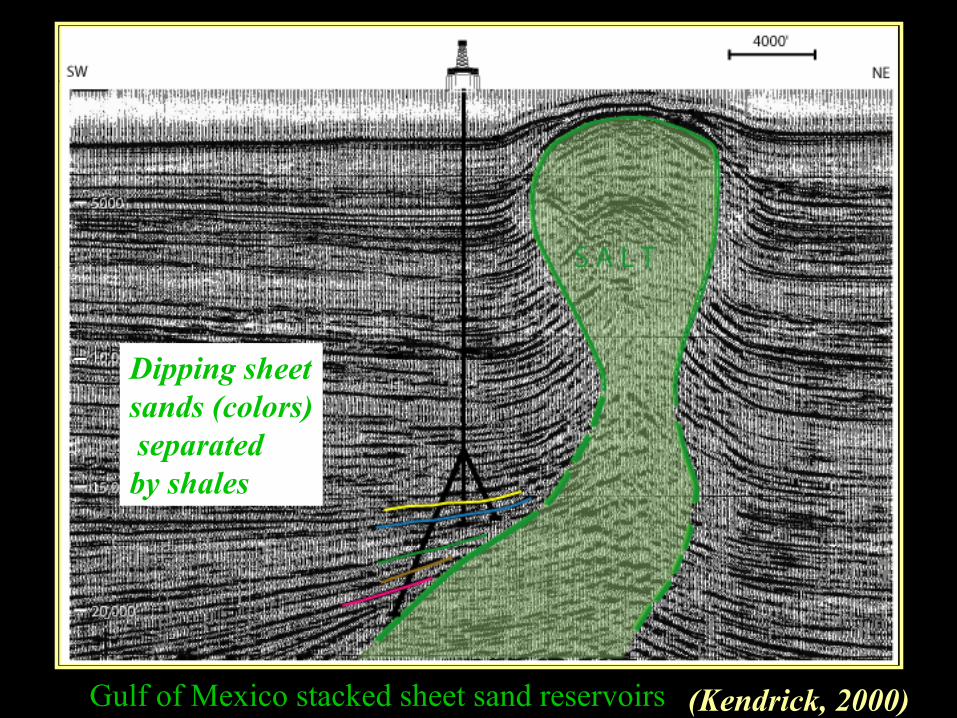
(Kendrick, 2000)Gulf of Mexico stacked sheet sand reservoirs
Dipping sheetsands (colors)separatedby shales

Dorn et.al, 2001
CAVE
Person
3D Seismic datavolume
Walk-in CAVE’s are excellent, but expensive!!

GEOLOGIC MODELING AREA, ARKANSAS: THE INEXPENSIVE CAVE IS CALLED AN OUTCROP!!!
55

OUTCROP GEOLOGIC MODELING AREA, ARKANSAS
55
A

‘OIL-WATER CONTACT’
‘UNCONFORMITY TOPSEAL’
‘RESERVOIR SANDSTONES’
‘SealingShale’
OUTCROP GEOLOGIC ‘RESERVOIR’ MODEL
OUTCROP ‘A’
A B C
“Imagination is more powerful than knowledge”Albert Einstein

Zone Net/Gross Por.(%) Perm.(md) Sw (%)A 0.70 29 1000 20B 0.40 26 300 20C 0.95 29 1000 20 D 0.96 30 2000 20
GEOLOGICRESERVOIR MODEL FORSIMULATION:
Dipping sandstoneswith unconformitytopseal; Layersseparated by sealing shalesA
B
CD
Oil/water contactSHALE
FAULT

Zone Net/Gross Por.(%) Perm.(md) Sw (%)A 0.70 29 1000 20B 0.40 26 300 20C 0.95 29 1000 20 D 0.96 30 2000 20
GEOLOGICRESERVOIR MODEL FORSIMULATION:
Dipping sandstoneswith unconformitytopseal; Layersseparated by sealing shales
Oil/watercontact

A
B
CD
ShOil/water contact
WELL PLACEMENTFOR SIMULATION:
On each fault block:-Vertical well thru D-Vertical well thru B-Horizontal well thru
B,C,D.

A
B
CD
SHOil/water contact
AFTER SIMULATION:Most oil out of horizontalwell, then Zone D, thenZone B.

•SEEING IS BELIEVING•BUILD SCALED GEOLOGIC MODEL
FOR SUBSURFACE PREDICTION:-FACIES-TRENDS-GEOMETRIES-DIMENSIONS-CONTINUITY/CONNECTIVITY
•3D GEOLOGIC MODELING FOR SIMULATION•IMPROVED & MORE ECONOMIC:
-WELL SPACING & PLACEMENT-RESERVOIR PERFORMANCE PREDICTION
ConVALUE OF OUTCROPSVALUE OF OUTCROPS

2001-02 AAPG Distinguished LectureFunded by the AAPG Foundation
through the J. Ben Carsey Memorial Endowment
Outcrop/Behind Outcrop Characterization of Deepwater (Turbidite) Petroleum Reservoir
Analogs: Why and How
Roger M. SlattUniversity of OklahomaNorman, Oklahoma