Embed Size (px)
Citation preview
Inspections Department 900 7th Avenue, PO Box 446
Garner, NC 27529 919‐772‐4688
What you need to know before building an attached or
self‐supported deck to your home.
Important Note: The Building Code also regu‐lates items such as the stringers and treads for steps, fastening (nailing and/or bolting) and bracing for lateral stability. Be sure to discuss these with the Plans Review personal if you have any questions about what the code requires.
Girder span tables from the Building Code for #2SYP and a 40lb. Live Load:
Joist span tables from the Building Code for #2SYP and a 40 lb. Live Load:
Figure 4 Figure 5
Figure 6 Figure 7
Our Recommendations for a “Minimum Code” and a “Code Plus” Deck ...
Town of Garner
Inspections Department
PO Box 446, 900 7th Avenue, Bldg. B
Garner, NC 27529
First Things First ...
Decisions You Need to Make ...
Everyone dreams of the “perfect deck”… But getting from Point A (the dream deck) to point B (planning and construction) is not always as easy. We want your deck to be perfect, but we must ensure that Town code and standards. This brochure will help you construct a safe code‐compliant “dream deck.” But, first things first… The Town of Garner requires a building permit for the construction of your deck before, so you must acquire your permit BEFORE you begin construction. For information on how and where to obtain your building permit, call or visit the Town of Garner Inspections Department at 900 Seventh Ave., Garner, NC 27529. Or call (919) 773‐4433. Office hours are Monday‐Friday from 8:00 am to 5:00 pm. Why the permit and inspections? To ensure that the deck will comply with local zoning regulations and with the North Carolina State Residen‐tial Building Code. The zoning regulations establish minimum setbacks that must be maintained from prop‐erty lines. The building code governs the method of construction, materials, means of support, attachment and requires safety features such as guard rails and hand rails.
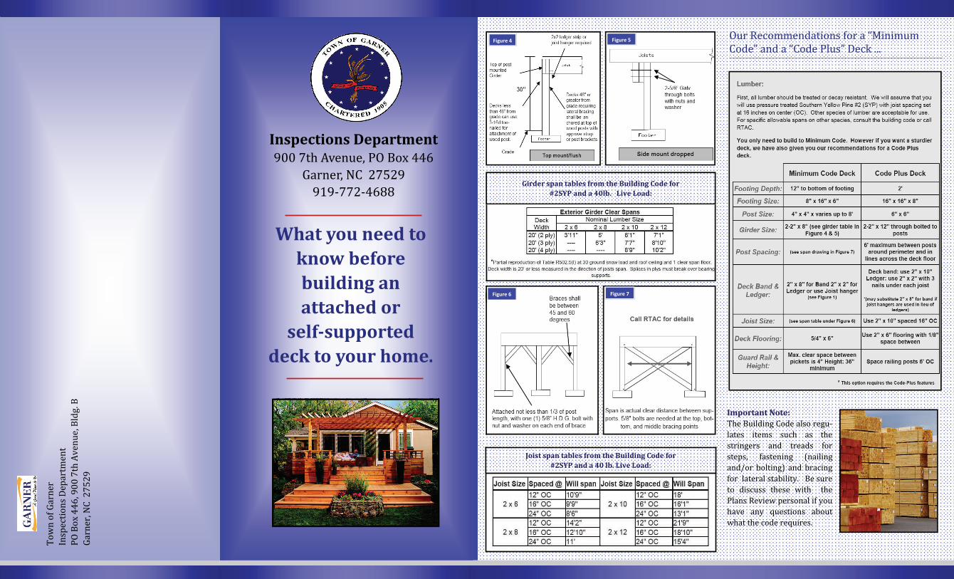
What distances will you span between supports? Your joist must be sized to carry lb. per sq. ft live load. In some instances, a girder is used to help meet this design criteria and to allow use of smaller individual floor joists (See floor joist span Figure 6)
How high off the ground will the floor of your deck be? If the walking surface of the deck is 30 inches off of the ground, your deck must be surrounded by guard rails which are a minimum of 36 inches in height. The steps for the deck must also have guard rails on both sides if there are 4 or more individual risers (spaces between steps). If the steps have a total rise of 30” or more above ground level, guard rails/ hand rails must also be provided on open sides of the steps. (See Figure 4) Bracing your deck for lateral support. If your planned deck is attached and over 4’ above the ground (measured from top of footing to deck floor), bracing for lateral support is required. Self supported decks greater than 30” in height (measured from top of footing to deck floor) also require bracing. Several methods of bracing are acceptable depending on whether the deck is free standing or attached (see Figure 6 & 7). Consult with Plans review personal at 919‐772‐4688 to select a method that meets code and will work best for your project.
Figure 2 Figure 3
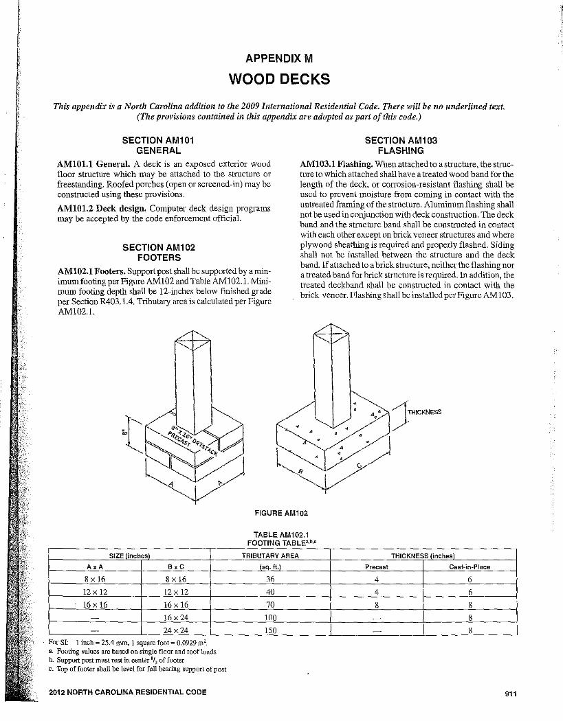
How deep and how large must the footings under support posts be? Each deck support post must be supported by con‐crete footing. The size of each footing is deter‐mined by the tributary load imposed on it. See the diagram below for a explanation of tributary load. Each footing must be dug down into undistributed soil and to a minimum depth of 12 inches.
Handrails, Guards and General Construction Figure 1
Will your deck be attached to the residence for support or will it be a “self‐supported” deck?
All Structures Except Brick Veneer
Brick Veneer Structures
Why do I need a permit and inspections? To ensure that the deck will comply with local zoning regulations and with the North Carolina State Residential Building Code. The zoning regulations establish minimum setbacks that must be maintained from property lines. The building code governs the method of construction, materials, means of support, attachment and requires safety features such as guard rails and hand rails.
If attached, this means the deck band will be connected to the house band and that your deck will be supported partially by the existing foundation of the house. Attached decks must be connected to the band or rim joist of the hours by 5/8 inch galvanized through bolts. Also, the existing siding (except brick) which covers the house band must be removed so that the deck band makes full con‐tact with the house band. Non‐aluminum, non‐corrosive flash‐ing must be installed between the deck and house bands. (see flashing detail Figure 1) to pre‐vent water from rotting the house band. See diagram for detail.
APPENDIX M
WOOD DECKS
This appendix is a North Carolina addition to the 2009 lntemational Residential Code. There will be no underlined text. (The provisions contained in this appendix are adopted as part of this code.)
SECTION AM101 GENERAL
AMlO!.l General. A deck is an exposed exterior wood floor structure which may be attached to the structure or freestanding. Roofed porcbes (open or screened-in) may be constructed using these proVisions.
AMlO!.2 Deck design. Computer deck design programs may be accepted by the code enforcement official.
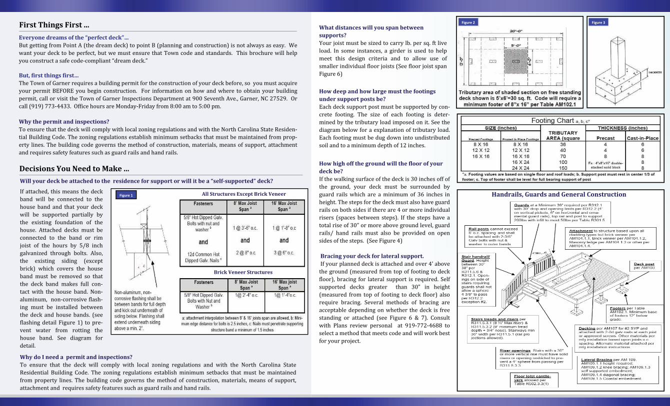
SECTION AM102 FOOTERS
AMl02.l Footers. SUppOlt post shall be supported by a minimum footing per Figure AMI02 and Table AM102.1. Minimum footing depth shall be 12-inches below finished grade per Section R403.1.4. Tributary area is calculated per Figure AMI02.1.
•
SECTION AM103 FLASHING
AMl03.l Flashing. When attached to a structure, the shucture to which attached shall have a treated wood band for the length of the deck, or corrosion-resistant flashing shall be used to prevent moisture from coming in contact with the untreated framing of the structure. Aluminum flashing sball not be used in conjunction with deck construction. The deck band and the structure band shall be constructed in contact with each other except on brick veneer structures and where plywood sheathing is required and properly flashed. Siding shall not be installed between the structure and the deck band. If attached to a brick structure, neither the flashing nor a treated band for brick structure is required. In addition, the treated deckband shall be conshucted in contact with the brick veneer. Flashing shall be installed per Figure AMI 03.
• •
• d • )nlICKNESS
FIGURE AM102
SIZE (inches)
AxA BxC
8 X 16 8 X 16
12 X 12 12 X 12
16 X 16 16 X 16
- 16 X 24
- 24x24
For SI: 1 inch = 25.4 mm, 1 square foot = O.0929m2. a Footing values are based on single floor and roof loads h. Support post must rest in center 1/3 of footer c. Top offooter shall be level for full bearing support of post
2012 NORTH CAROLINA RESIDENTIAL CODE
TABLE AM102.1 FOOTING TABLE"b,o
TRIBUTARY AREA
(sq. ft.)
36
40
70
100
150
THICKNESS (inches)
Precast Cast-in-Place
4 6
4 6
8 8
8
- 8
911
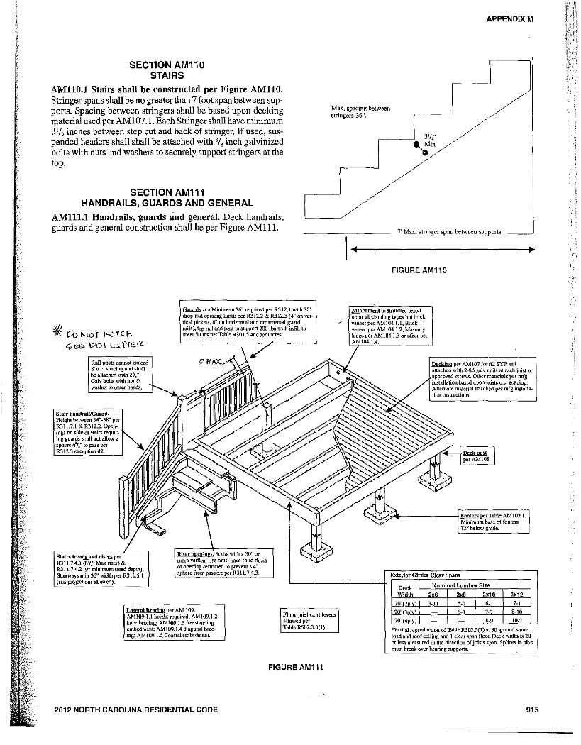
SECTION AM110 STAIRS
AMllO.1 Stairs shall be constructed per Figure AMllO. Stringer spans shall be no greater than 7 foot span between sup· ports. Spacing between stringers shall be based upon decking material used per AM I 07 .1. Each Stringer shall have minimum 31/ 2 inches between step cut and back of stringer. !fused, suspended headers shall shall be attached with 3/8 inch galvinized bolts with nuts and washers to securely support stringers at the top.
SECTION AM111 HANDRAILS, GUARDS AND GENERAL
AMI11.I Handrails, guards and general. Deck handrails, guards and general construction shall be per Figure AMI I!.
~ Cb I-o-loi ND,C H """" \?c) \ L" Y"'" \<..
Stairs treads And risers per R311.7.4.1 (8'1," Max riser) & R31 1.7.4.2 (9" minimum trelId depth). Stairways min 36" width per R311.5.1 (rail projecliolls allowed).
Guards at a Minimum 36" required per R312.1 with 30" drop and openIng limits per R312.2 & R312.3 (4" on vertical pickets, 6" au horizontal and ornamental guard rails), lop rail and past to support 200 Ibs with infill to meet 50 Ibs per Table R30I.5 and footnotes.
Max. spacing between stringers 36",
I aterlll Bracing per AM 109. AM109.1.l height required; AM109.l.2 knee hracing; AM109.1.3 freestanding embedment; AM109.1.4 diagonal bracing; AM 109.1.5. Coastal em bedmen L
Floor loist cantilevers allowed per Table R502.3.3(l)
FIGURE AM111
2012 NORTH CAROLINA RESIDENTIAL CODE
APPENDIX M
7' Max. stringer span between supports
FIGURE AM110
Decking per AMI07 for 112 SYP and atl<l.ehcd with 2-8d galv onit. Rt p',,~h jni~t or
. Otller ~aterials per ~g
Exterior Girder Clear Spans
Deck Nominal Lumber Size
Width 2,6 2" 2x10 2x12
20' 2 I 3-11 '-0 6-1
20' 3 I 6-3 7-7 8-10
20' 4 1 8-9 10-2
tpartial reproduction of Table R502.5( 1) at 30 ground snow load and roof ceiling and 1 clear span floor. De<:k width is 20' OT less measnred in the direction of joists spall. Splices ill plys
915
"
·1 I I ~,
I
I t
t I I :! I 1
I 1 ,
,I i t
APPENDIX M
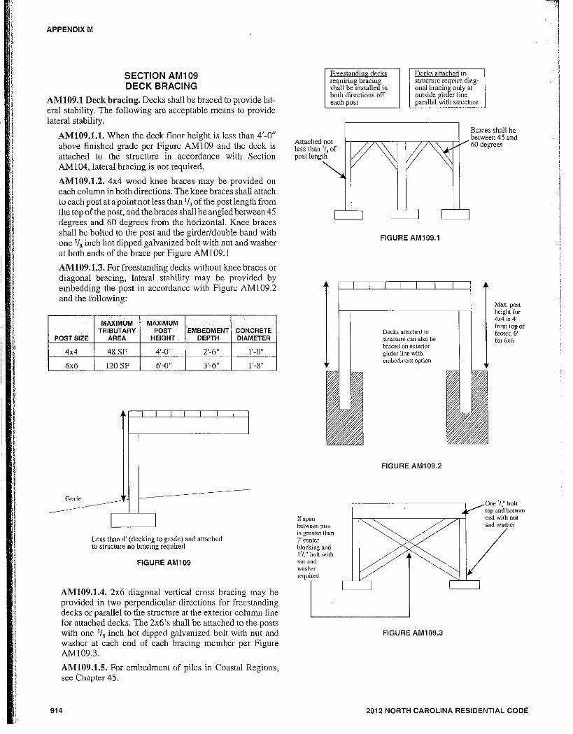
SECTION AM109 DECK BRACING
AMI09.1 Deck bracing. Decks shall be braced to provide lat· eral stability. The following are acceptable means to provide lateral stability.
AMI09.1.1. When the deck floor height is less than 4'·0" above finished grade per Figure AMI09 and the deck is attached to the structure in accordance with Section AM 104, lateral bracing is not required.
AMI09.1.2. 4x4 wood knee braces may be provided on each column in both directions. The knee braces shall attach to each post at a point not less than 1/, of the post length from the top of the post, and the braces shall be angled between 45 degrees and 60 degrees from the horizontal. Knee braces shall be bolted to the post and the girder/double band with one 'jIg inch hot dipped galvanized bolt with nut and washer at both ends of the brace per Figure AMI09.1
AMI09.1.3. For freestanding decks without kuee braces or diagonal bracing, lateral stability may be provided by embedding the post in accordance with Figure AMI09.2 and the fonowing:
POST SIZE
4x4
6x6
MAXIMUM TRIBUTARY
AREA
48 SF
[20 SF
MAXIMUM POST EMBEDMENT CONCRETE
HEIGHT DEPTH DIAMETER
4'·0" 2'·6" ['·0"
6'·0" 3'·6" ['·8"
--~-----
Less than 4' (decking to grade) and attached to structure no bracing required
FIGURE AM1 09
AMI09.1.4. 2x6 diagonal vertical cross bracing may be provided in two perpendicular directions for freestanding decks or parallel to the structure at the exterior column line for attached decks. The 2x6's shall be attached to the posts with one '/, inch hot dipped galvanized bolt with nut and washer at each end of each bracing member per Figure AM109.3.
AMI09.1.S. For embedment of piles in Coastal Regions, see Chapter 45.
914
Freestandin 0- decks requiring bracing shall be installed in both directions off each post
Decks attached to structure require diagonal bracing only at outside girder line parallel with structure
Attached not less than 'I, of post lengtn
Braces shall be
'-r-7:"';:---,-,----cT7'C'c-,-V between 45 and I 60 degrees
If span betwet!n post is greater than 7' center blocking and 1'1," bolL with nul and w[Jsher required
FIGURE AM1 09.1
Decks attached to structure can also be braced on exterior girder line with embedment option
FIGURE AM109.2
FIGURE AM109.3
Max post height for 4x4 is 4' from top of footer, 6' for 6x6
One 'I," bolt top and bottom end with nul
7
2012 NORTH CAROLINA RESIDENTIAL CODE
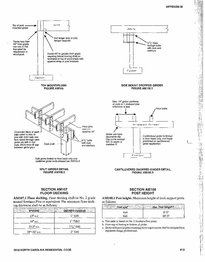
Top of post mounted gir
lo der
/ than Decks less
48" from gr can use 3-toenailed fa attachment wood post.
ade 16d r 01
Jo!£'t ? h
\'''~"'~' hanger required or joist
Decks 48" or greater I rom grade 9 shall be requiring lateral bracin
anchored at top of wo approve strap or post
ad posts with brackets
I roo"te-r I
Connector block at each joist nailed to side 01 joist with 3-8d nails and face nailed through each girder ply with 2-16d nails. Block must iill gap between girder ply's
TOP MOUNTIFLUSH FIGURE AM1 OS
Deck post
Split girder limited to floor loads only and cantilever girder ends allowed per AMi 05.3
SPLIT GIRDER DETAIL FIGURE AM1 OS.2
SECTION AM1 07 FLOOR DECKING
Floor joist max o.c_ spacing 16"
2_5/" bolts
-with nuts and washers
AMI07.1 Floor decking. Floor decking shall be No.2 grade treated Southern Pine or equivalent. The minimum floor decking thickness shall be as follows:
i;/i/; i'; V' ' •• , ·..R~ckii<~(~Rmt';all'· .'0.'
12" O.C 1" S4S
16" D.C. I"T&G
19.2" D.C.
24"-36" o.c. 2" S4S
2012 NORTH CAROLINA RESIDENTIAL CODE
APPENDIX M
I Joists
~ 2-'1,'· Galv. through bolts with nuts and washers
rooter I
SIDE MOUNT DROPPED GIRDER FIGURE AM1 OS.1
Max. 16" girder cantilever at ends or 1 rimlband joist whichever is less
{
~ Floor joists
Dropp(?cl Glrcl~>v'
! Girder can have decorative dip. Clip not to exceed 0/4. O=depth of member 14
Cantilevered girder is limited to floor loads only, roof loads prohibited on cantilevered girder application
Foo-ter
CANTILEVERED DROPPED GIRDER DETAIL FIGURE AM10S.3
SECTION AM108 POST HEIGHT
AMIOS.l Post height Maximum height of deck support posts as follows:
Ii.·;·.··i·· •• )+·.:·,···'··~,.··.···.···: .. :,,:··.·· '; ···Ma"'~~i;iii$i~~,·~.·. 4x4 8'-0" 6x6 20'-0"
a. This table is based on No.2 Southern Pine posts. b. From top of footing to bottom of girder. c. Decks with post heights exceeding these requirements shall be designed by a
registered design professional.
913
l 1".
., , ,
.;:. i . il,!
. ;;1."1' ' .. .. , .,
'j'
.-, ': ... , ': .1 -l
APPENDIX M
I I -(----
I I I I
-~---I I
20'-0"
5'-0"
I
I I ---,-I I I I I ---,-I I
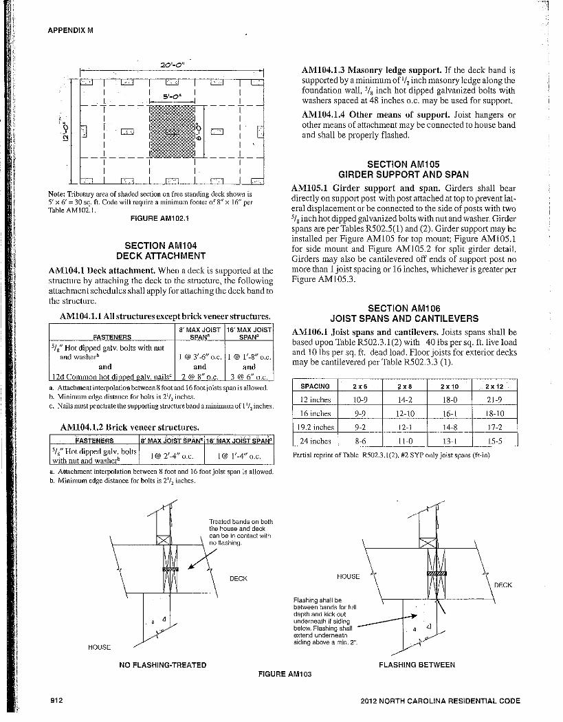
Note: Tributary area of shaded section on free standing deck shown is 5' x 6' = 30 sq. ft. Code will require a minimum footer of 8 f
' X 16" per Table AM102.1.
FIGURE AM1 02.1
SECTION AM104 DECK ATTACHMENT
AMI04.1 Deck attachment. When a deck is supported at the structure by attaching the deck to the structure, the following attachment schedules shall apply for attaching the deck band to the structure.
AMI04.1.1 All structures except brick veneer structures.
8' MAX JOIST 16' MAX JOIST FASTENERS SPAN3 SPAN3
31t Hot dipped galv. bolts with nut and washerb 1 @ 3'-6" o.c. 1 @ 1'-8/1 D.C.
and and and 12d Cornmon hot dinned galv. nailsc 2 @ 8" o.c. 3 @ 6" D.C.
a. Attachment interpolation between 8 root and 16 foot joists span is allowed. h. Minimum edge distance for bolts is 21/2 inches. c. Nails must penetrate lhe supporting structure band a minimum of 11/2 inches.
AMI04.1.2 Brick veneer structures. . . ..
16' ~AX JOiST SPAN3 FASTENERS 8' MAX JOIST SPAN3
s/g" Hot dipped galv. bolts I@ 2'_4" a.c. I@ 1'-4" a.C. with nut and washerb
a. Attachment interpolation between 8 foot and 16 footjaist span is allowed. h. Minimum edge distance for bolts is 21/2 inches .
HOUSE
. Y
Treated bands on both the house and deck can be in contact with
\------J"'T'l'-.---\ no flashing.
DECK
NO FLASHING-TREATED
AMI04.1.3 Masonry ledge support. If the deck band is supported by a minimum ofI/, inch masonry ledge along the foundation wall. 'I, inch hot dipped galvanized bolts with washers spaced at 48 inches D.C. may be used for support.
AMI04.1.4 Other means of support. Joist hangers or other means of attachment may be connected to house band and shall be properly flashed.
SECTION AM1 05 GIRDER SUPPORT AND SPAN
AMI 05. 1 Girder support and span. Girders shall bear directly on support post with post attached at top to prevent lateral displacement or be connected to the side of posts with two 5/8 inch hot dipped galvanized bolts with nut and washer. Girder spans are per Tables RS02.S(1) and (2). Girder support may be installed per Figure AMIOS for top mount; Figure AMlOS.l for side mount and Figure AM10S.2 for split girder detail. Girders may also be cantilevered off ends of support post no more than 1 joist spacing or 16 inches, whichever is greater per Figure AM10S.3.
SECTION AM106 JOIST SPANS AND CANTILEVERS
AMI06.1 Joist spans and cantilevers. Joists spans shall be based upon Table RS02.3.1(2) with 40 lbs per sq. ft.live load and 10 Ibs per sq. ft. dead load. Floor joists for exterior decks may be cantilevered per Table RS02.3.3 (1).
SPACING 2.6 ;i!x8 2x 1,0 2 x 12
12 inches 10-9 14-2 18-0 21-9
16 inches 9-9 12-10 16-1 18-10
19.2 inches 9-2 12-1 14-8 17-2
24 inches 8-6 tl-O 13-1 15-5
Partial reprint of Table R502.3.1(2), #2 SYP only joist spans (ft-in)
HOUSE
Flashing shall be between bands for full depth and kick out underneath if siding below. Flashing shall extend underneath siding above a min. 2".
FLASHING BETWEEN FIGURE AM1 03
912 2012 NORTH CAROLINA RESIDENTIAL CODE
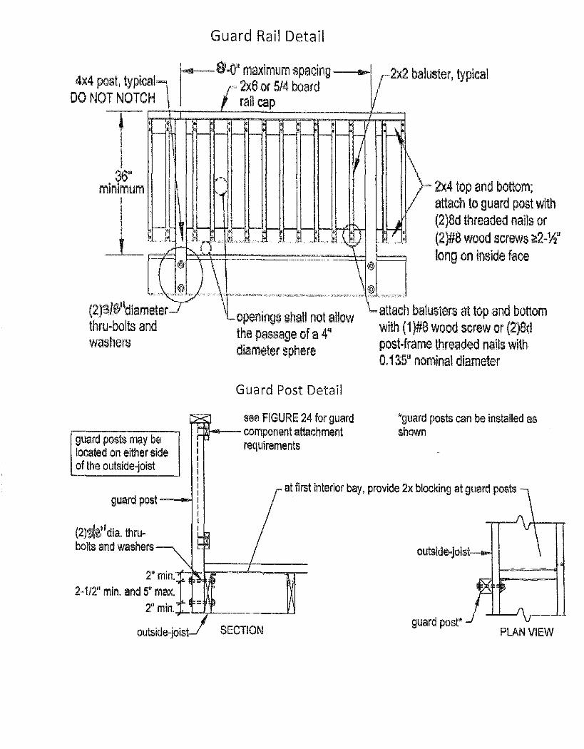
Guard Rail Detail
I SI·O" m, aximum spacing "'" r2x2 baluster, typical 4x4 post, typical"""l IOC 2x6 Of 5/4 board
DO NOT NOTCH \ rail cap /
t ~C;:;:::;;;~::;:::;;:::::;;;:::;;::;::;~;:::;;l
,", minimum I '. I 2x4 top and bottom;
I I '. attach to guard post with
I ;-J~l F~O" ,~.i,,-,,-L,_~-,'_;)--i, •• ~'·l' .r->_ t' \tl" ~: m:~ :~~~d::r;;~S~~~w ---1'_ u /1- h I, 1 '. - 'f long on inside face
{® \ \* (2)'li~ld;am"~ 't~;;~ 'h~1 :\ a\low ; !!;;;;;~h balus\,,, ill lOp and bottom thru~bolts and the passage of a 4" with (1}#8 wood screw or (2)8d washers diameter sphere post·frame threaded nails with
0,135" nominal diameter
guard posts may be located on either side of the outside-joist
Guard Post Detail
see FIGURE 24 for guard 1J11-.-- component attachment
reqUirements
"guard posts can be installed as shown
guard posl-~ at first interior bay, provide 2x blocking at guard posts
(2)~1~1; dia. thru· bolts and washers
2" min,), ?1~li~=t:==n= 2-112" min. and 5" max.
= 2"min, . +-L--I,L---_--LJ
outside-joist SECTION guard post'
PLAN VIEW
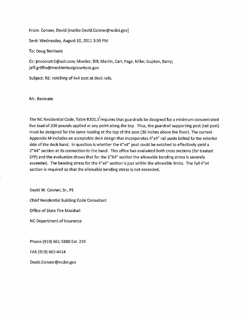
From: Conner, David [mailto:[email protected]]
Sent: Wednesday, August 10, 2011 3:39 PM
To: Doug Beninate
Cc: [email protected]; Moeller, Bill; Martin, Carl; Page, Mike; Gupton, Barry;
Subject: RE: notching of 4x4 post at deck rails.
Mr. Beninate
The NC Residential Code, Table R301.s' requires that guardrails be designed for a minimum concentrated
live load of 200 pounds applied at any point along the top. Thus, the guardrail supporting post (rail post)
must be designed for the same loading at the top of the post (36 inches above the floor). The current
Appendix M includes an acceptable deck design that incorporates 4"x4" rail posts bolted to the exterior
side of the deck band. In question is whether the 4"x4" post could be notched to effectively yield a
2"X4" section at its connection to the band. This office has evaluated both cross sections (for treated
SYP) and the evaluation shows that for the 2"X4" section the allowable bending stress is severely
exceeded. The bending stress for the 4"x4" section is just within the allowable limits. The full4"x4
section is required so that the allowable bending stress is not exceeded.
David W. Conner, Sr., PE
Chief Residential Building Code Consultant
Office of State Fire Marshall
NC Department of Insurance
Phone (919) 661-5880 Ext. 229
FAX (919) 662-4414