Embed Size (px)
Citation preview
Washington Office: 1707 H Street NW Suite 600 • Washington DC 20006-3919 • 202-223-6133 • FAX: 202-223-6162
Cambridge Headquarters: Two Brattle Square • Cambridge MA 02238-9105 • 617-547-5552 • FAX: 617-864-9405 California Office: 2397 Shattuck Avenue Suite 203 • Berkeley CA 94704-1567 • 510-843-1872 • FAX: 510-843-3785
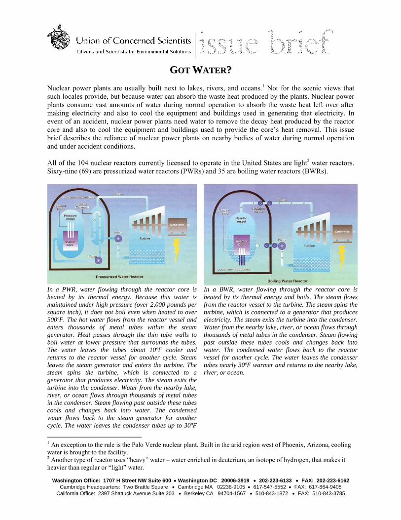
GGOOTT WWAATTEERR?? Nuclear power plants are usually built next to lakes, rivers, and oceans.1 Not for the scenic views that such locales provide, but because water can absorb the waste heat produced by the plants. Nuclear power plants consume vast amounts of water during normal operation to absorb the waste heat left over after making electricity and also to cool the equipment and buildings used in generating that electricity. In event of an accident, nuclear power plants need water to remove the decay heat produced by the reactor core and also to cool the equipment and buildings used to provide the core’s heat removal. This issue brief describes the reliance of nuclear power plants on nearby bodies of water during normal operation and under accident conditions. All of the 104 nuclear reactors currently licensed to operate in the United States are light2 water reactors. Sixty-nine (69) are pressurized water reactors (PWRs) and 35 are boiling water reactors (BWRs).
In a PWR, water flowing through the reactor core is heated by its thermal energy. Because this water is maintained under high pressure (over 2,000 pounds per square inch), it does not boil even when heated to over 500ºF. The hot water flows from the reactor vessel and enters thousands of metal tubes within the steam generator. Heat passes through the thin tube walls to boil water at lower pressure that surrounds the tubes. The water leaves the tubes about 10ºF cooler and returns to the reactor vessel for another cycle. Steam leaves the steam generator and enters the turbine. The steam spins the turbine, which is connected to a generator that produces electricity. The steam exits the turbine into the condenser. Water from the nearby lake, river, or ocean flows through thousands of metal tubes in the condenser. Steam flowing past outside these tubes cools and changes back into water. The condensed water flows back to the steam generator for another cycle. The water leaves the condenser tubes up to 30ºF
In a BWR, water flowing through the reactor core is heated by its thermal energy and boils. The steam flows from the reactor vessel to the turbine. The steam spins the turbine, which is connected to a generator that produces electricity. The steam exits the turbine into the condenser. Water from the nearby lake, river, or ocean flows through thousands of metal tubes in the condenser. Steam flowing past outside these tubes cools and changes back into water. The condensed water flows back to the reactor vessel for another cycle. The water leaves the condenser tubes nearly 30ºF warmer and returns to the nearby lake, river, or ocean.
1 An exception to the rule is the Palo Verde nuclear plant. Built in the arid region west of Phoenix, Arizona, cooling water is brought to the facility. 2 Another type of reactor uses “heavy” water – water enriched in deuterium, an isotope of hydrogen, that makes it heavier than regular or “light” water.
October xx, 2007 Page 2 of 14
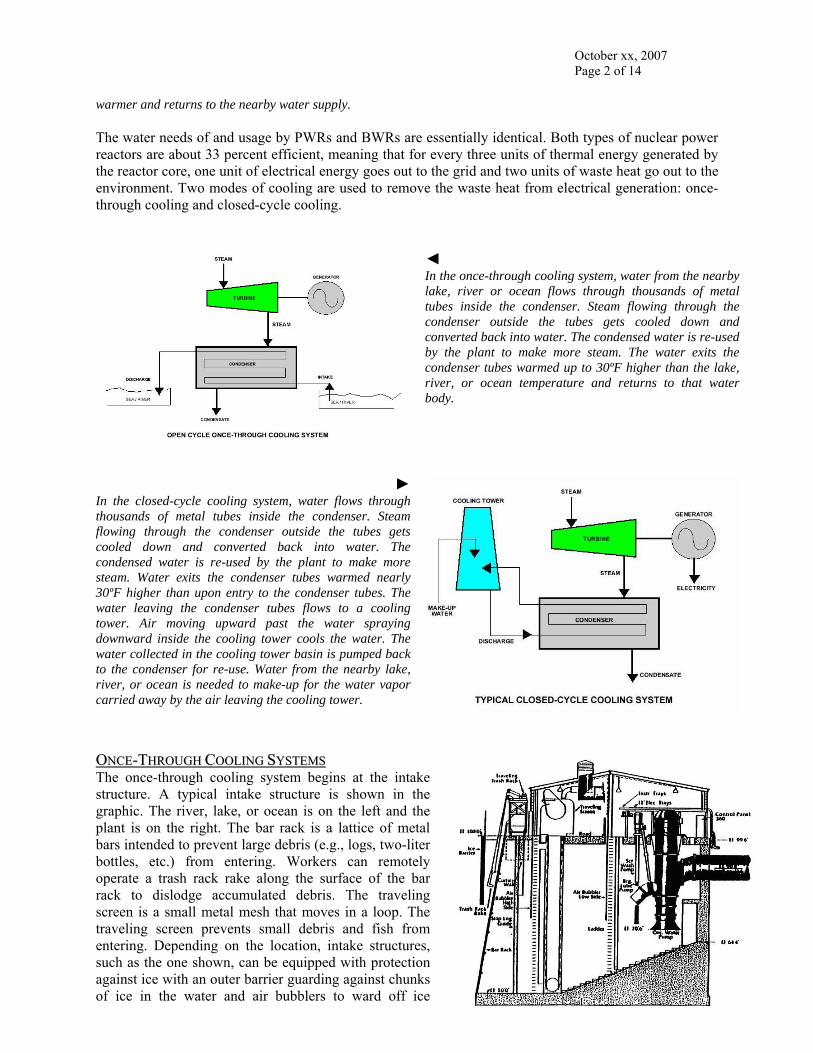
warmer and returns to the nearby water supply. The water needs of and usage by PWRs and BWRs are essentially identical. Both types of nuclear power reactors are about 33 percent efficient, meaning that for every three units of thermal energy generated by the reactor core, one unit of electrical energy goes out to the grid and two units of waste heat go out to the environment. Two modes of cooling are used to remove the waste heat from electrical generation: once-through cooling and closed-cycle cooling.
◄ In the once-through cooling system, water from the nearby lake, river or ocean flows through thousands of metal tubes inside the condenser. Steam flowing through the condenser outside the tubes gets cooled down and converted back into water. The condensed water is re-used by the plant to make more steam. The water exits the condenser tubes warmed up to 30ºF higher than the lake, river, or ocean temperature and returns to that water body.
►In the closed-cycle cooling system, water flows through thousands of metal tubes inside the condenser. Steam flowing through the condenser outside the tubes gets cooled down and converted back into water. The condensed water is re-used by the plant to make more steam. Water exits the condenser tubes warmed nearly 30ºF higher than upon entry to the condenser tubes. The water leaving the condenser tubes flows to a cooling tower. Air moving upward past the water spraying downward inside the cooling tower cools the water. The water collected in the cooling tower basin is pumped back to the condenser for re-use. Water from the nearby lake, river, or ocean is needed to make-up for the water vapor carried away by the air leaving the cooling tower.
OONNCCEE--TTHHRROOUUGGHH CCOOOOLLIINNGG SSYYSSTTEEMMSS The once-through cooling system begins at the intake structure. A typical intake structure is shown in the graphic. The river, lake, or ocean is on the left and the plant is on the right. The bar rack is a lattice of metal bars intended to prevent large debris (e.g., logs, two-liter bottles, etc.) from entering. Workers can remotely operate a trash rack rake along the surface of the bar rack to dislodge accumulated debris. The traveling screen is a small metal mesh that moves in a loop. The traveling screen prevents small debris and fish from entering. Depending on the location, intake structures, such as the one shown, can be equipped with protection against ice with an outer barrier guarding against chunks of ice in the water and air bubblers to ward off ice
October xx, 2007 Page 3 of 14
buildup on the traveling screens. Nuclear power plants use two to four circulating water pumps for each reactor unit. Each circulating water pump with its electric motor stands nearly 40 feet tall and supplies over 100,000 gallons of water. The piping from the discharge of the circulating pumps runs underground from the intake structure to the turbine building.
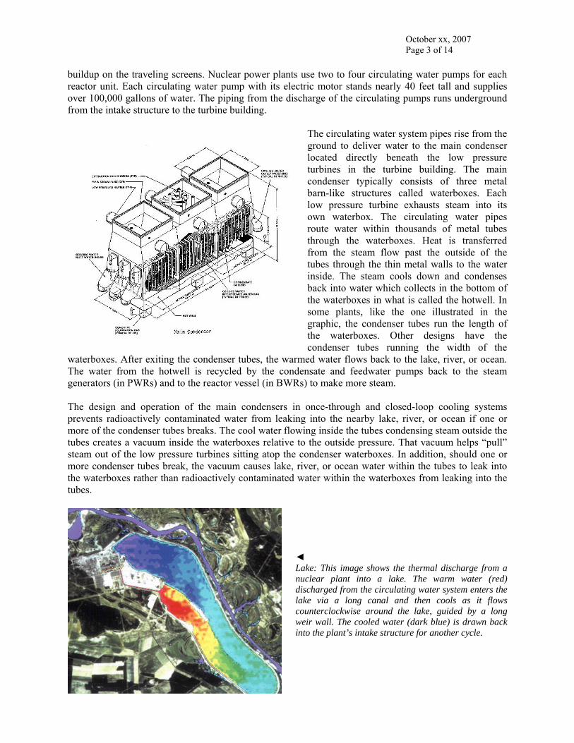
The circulating water system pipes rise from the ground to deliver water to the main condenser located directly beneath the low pressure turbines in the turbine building. The main condenser typically consists of three metal barn-like structures called waterboxes. Each low pressure turbine exhausts steam into its own waterbox. The circulating water pipes route water within thousands of metal tubes through the waterboxes. Heat is transferred from the steam flow past the outside of the tubes through the thin metal walls to the water inside. The steam cools down and condenses back into water which collects in the bottom of the waterboxes in what is called the hotwell. In some plants, like the one illustrated in the graphic, the condenser tubes run the length of the waterboxes. Other designs have the condenser tubes running the width of the
waterboxes. After exiting the condenser tubes, the warmed water flows back to the lake, river, or ocean. The water from the hotwell is recycled by the condensate and feedwater pumps back to the steam generators (in PWRs) and to the reactor vessel (in BWRs) to make more steam. The design and operation of the main condensers in once-through and closed-loop cooling systems prevents radioactively contaminated water from leaking into the nearby lake, river, or ocean if one or more of the condenser tubes breaks. The cool water flowing inside the tubes condensing steam outside the tubes creates a vacuum inside the waterboxes relative to the outside pressure. That vacuum helps “pull” steam out of the low pressure turbines sitting atop the condenser waterboxes. In addition, should one or more condenser tubes break, the vacuum causes lake, river, or ocean water within the tubes to leak into the waterboxes rather than radioactively contaminated water within the waterboxes from leaking into the tubes.
◄ Lake: This image shows the thermal discharge from a nuclear plant into a lake. The warm water (red) discharged from the circulating water system enters the lake via a long canal and then cools as it flows counterclockwise around the lake, guided by a long weir wall. The cooled water (dark blue) is drawn back into the plant’s intake structure for another cycle.
October xx, 2007 Page 4 of 14
► River: This drawing shows the discharge piping routed along the river bottom to diffuse the warm water discharged from the circulating water system into the river. The diffuser pipes extend out into the river along its bed for optimal mixing between the warm discharge water and the cooler river water.
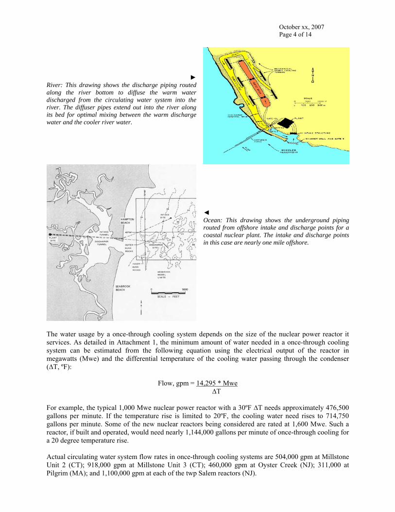
◄ Ocean: This drawing shows the underground piping routed from offshore intake and discharge points for a coastal nuclear plant. The intake and discharge points in this case are nearly one mile offshore.
The water usage by a once-through cooling system depends on the size of the nuclear power reactor it services. As detailed in Attachment 1, the minimum amount of water needed in a once-through cooling system can be estimated from the following equation using the electrical output of the reactor in megawatts (Mwe) and the differential temperature of the cooling water passing through the condenser (∆T, ºF):
Flow, gpm = 14,295 * Mwe ∆T
For example, the typical 1,000 Mwe nuclear power reactor with a 30ºF ∆T needs approximately 476,500 gallons per minute. If the temperature rise is limited to 20ºF, the cooling water need rises to 714,750 gallons per minute. Some of the new nuclear reactors being considered are rated at 1,600 Mwe. Such a reactor, if built and operated, would need nearly 1,144,000 gallons per minute of once-through cooling for a 20 degree temperature rise. Actual circulating water system flow rates in once-through cooling systems are 504,000 gpm at Millstone Unit 2 (CT); 918,000 gpm at Millstone Unit 3 (CT); 460,000 gpm at Oyster Creek (NJ); 311,000 at Pilgrim (MA); and 1,100,000 gpm at each of the twp Salem reactors (NJ).
October xx, 2007 Page 5 of 14
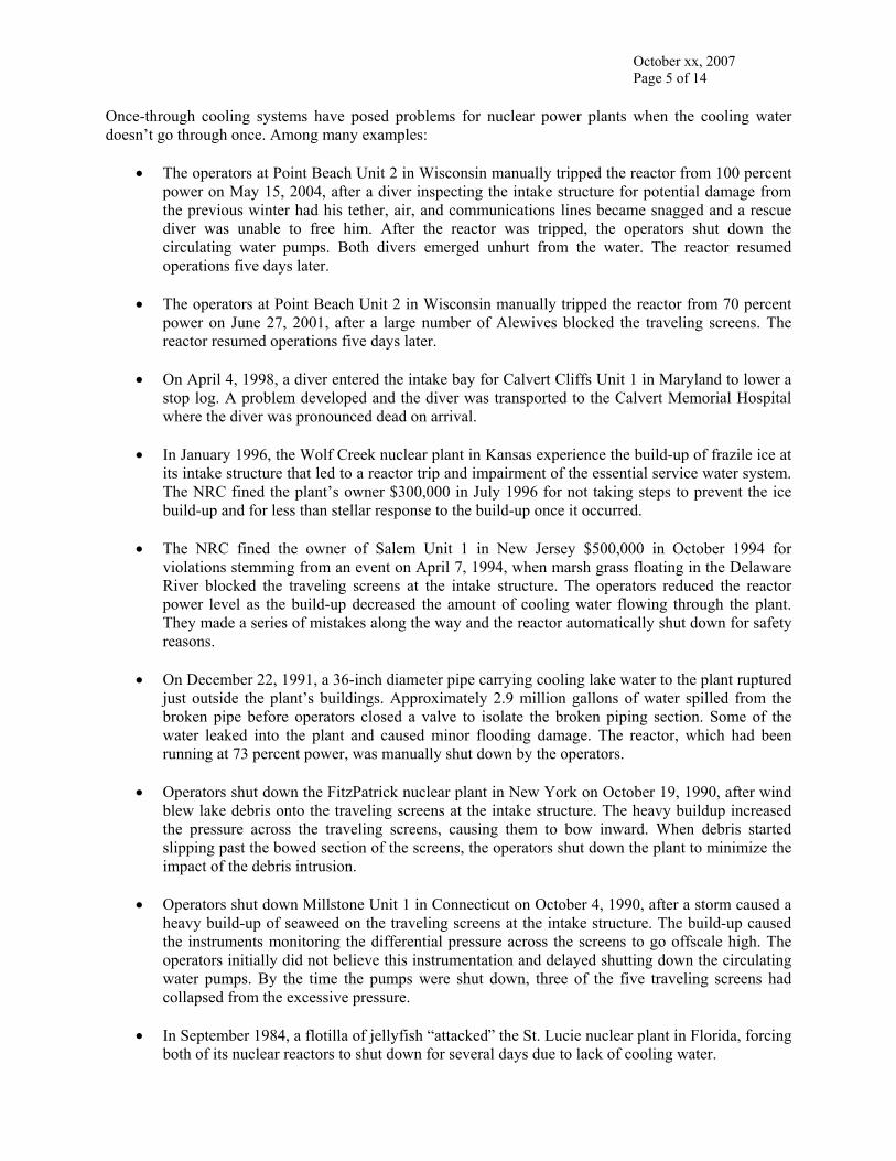
Once-through cooling systems have posed problems for nuclear power plants when the cooling water doesn’t go through once. Among many examples:
• The operators at Point Beach Unit 2 in Wisconsin manually tripped the reactor from 100 percent power on May 15, 2004, after a diver inspecting the intake structure for potential damage from the previous winter had his tether, air, and communications lines became snagged and a rescue diver was unable to free him. After the reactor was tripped, the operators shut down the circulating water pumps. Both divers emerged unhurt from the water. The reactor resumed operations five days later.
• The operators at Point Beach Unit 2 in Wisconsin manually tripped the reactor from 70 percent
power on June 27, 2001, after a large number of Alewives blocked the traveling screens. The reactor resumed operations five days later.
• On April 4, 1998, a diver entered the intake bay for Calvert Cliffs Unit 1 in Maryland to lower a
stop log. A problem developed and the diver was transported to the Calvert Memorial Hospital where the diver was pronounced dead on arrival.
• In January 1996, the Wolf Creek nuclear plant in Kansas experience the build-up of frazile ice at
its intake structure that led to a reactor trip and impairment of the essential service water system. The NRC fined the plant’s owner $300,000 in July 1996 for not taking steps to prevent the ice build-up and for less than stellar response to the build-up once it occurred.
• The NRC fined the owner of Salem Unit 1 in New Jersey $500,000 in October 1994 for
violations stemming from an event on April 7, 1994, when marsh grass floating in the Delaware River blocked the traveling screens at the intake structure. The operators reduced the reactor power level as the build-up decreased the amount of cooling water flowing through the plant. They made a series of mistakes along the way and the reactor automatically shut down for safety reasons.
• On December 22, 1991, a 36-inch diameter pipe carrying cooling lake water to the plant ruptured
just outside the plant’s buildings. Approximately 2.9 million gallons of water spilled from the broken pipe before operators closed a valve to isolate the broken piping section. Some of the water leaked into the plant and caused minor flooding damage. The reactor, which had been running at 73 percent power, was manually shut down by the operators.
• Operators shut down the FitzPatrick nuclear plant in New York on October 19, 1990, after wind
blew lake debris onto the traveling screens at the intake structure. The heavy buildup increased the pressure across the traveling screens, causing them to bow inward. When debris started slipping past the bowed section of the screens, the operators shut down the plant to minimize the impact of the debris intrusion.
• Operators shut down Millstone Unit 1 in Connecticut on October 4, 1990, after a storm caused a
heavy build-up of seaweed on the traveling screens at the intake structure. The build-up caused the instruments monitoring the differential pressure across the screens to go offscale high. The operators initially did not believe this instrumentation and delayed shutting down the circulating water pumps. By the time the pumps were shut down, three of the five traveling screens had collapsed from the excessive pressure.
• In September 1984, a flotilla of jellyfish “attacked” the St. Lucie nuclear plant in Florida, forcing
both of its nuclear reactors to shut down for several days due to lack of cooling water.
October xx, 2007 Page 6 of 14
• Operators shut down Millstone Unit 1 in Connecticut on September 1, 1972, after condenser tube
failures allowed water from the Atlantic Ocean to be pumped into the reactor vessel. Serious chloride corrosion from the sea water disabled 114 of the 120 local power range monitors in the reactor core and required replacement of feedwater spargers and several other components before the reactor could restart.
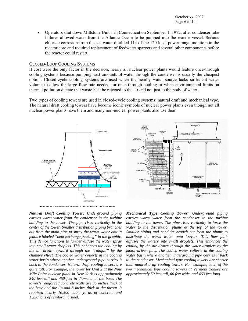
CCLLOOSSEEDD--LLOOOOPP CCOOOOLLIINNGG SSYYSSTTEEMMSS If cost were the only factor in the decision, nearly all nuclear power plants would feature once-through cooling systems because pumping vast amounts of water through the condenser is usually the cheapest option. Closed-cycle cooling systems are used when the nearby water source lacks sufficient water volume to allow the large flow rate needed for once-through cooling or when environmental limits on thermal pollution dictate that waste heat be rejected to the air and not just to the body of water. Two types of cooling towers are used in closed-cycle cooling systems: natural draft and mechanical type. The natural draft cooling towers have become iconic symbols of nuclear power plants even though not all nuclear power plants have them and many non-nuclear power plants also use them.
Natural Draft Cooling Tower: Underground piping carries warm water from the condenser in the turbine building to the tower. The pipe rises vertically in the center of the tower. Smaller distribution piping branches out from the main pipe to spray the warm water onto a feature labeled “heat exchange packing” in the graphic. This device functions to further diffuse the water spray into small water droplets. This enhances the cooling by the air drawn upward through the “rainfall” by the chimney effect. The cooled water collects in the cooling water basin where another underground pipe carries it back to the condenser. Natural draft cooling towers are quite tall. For example, the tower for Unit 2 at the Nine Mile Point nuclear plant in New York is approximately 540 feet tall and 450 feet in diameter at the base. The tower’s reinforced concrete walls are 36 inches thick at the base and the lip and 8 inches thick at the throat. It required nearly 16,500 cubic yards of concrete and 1,230 tons of reinforcing steel.
Mechanical Type Cooling Tower: Underground piping carries warm water from the condenser in the turbine building to the tower. The pipe rises vertically to force the water to the distribution plume at the top of the tower. Smaller piping and conduits branch out from the plume to distribute the warm water onto louvers. This flow path diffuses the watery into small droplets. This enhances the cooling by the air drawn through the water droplets by the motor-driven fans. The cooled water collects in the cooling water basin where another underground pipe carries it back to the condenser. Mechanical type cooling towers are shorter than natural draft cooling towers. For example, each of the two mechanical type cooling towers at Vermont Yankee are approximately 50 feet tall, 60 feet wide, and 463 feet long.
October xx, 2007 Page 7 of 14
The closed-cycle cooling system label is a bit of a misnomer because plants with mechanical type cooling towers consume water from nearby lakes, rivers, and oceans and also return water to those bodies. Water is needed to compensate for the water vapor leaving the cooling towers with the cooling air flow. The amount of makeup is far less than the amount of water needed for once-through cooling systems, but it is not negligible. When both reactors at the Susquehanna nuclear plant in Pennsylvania operate in summer, nearly 30 million gallons of makeup water per day (or nearly 21,000 gallons per minute) are needed from the river to compensate for cooling tower drift. Water must also be discharged from closed-cycle cooling systems in order to control the chemistry of the recycled water and to limit the build-up of sediment and other debris in the cooling tower basins. The Susquehanna nuclear plant uses another 11 million gallons per day (about 7,600 gallons per minute) from the river that balances the discharge flow rate back to the river for cooling tower basis chemistry control. Actual circulating water system flow rates in closed-loop cooling systems are 480,000 gpm at Davis-Besse (OH); 552,000 gpm at Hope Creek (NJ); and 580,000 gpm at Nine Mile Point Unit 2 (NY); Closed-loop cooling systems have also posed problems for nuclear power plants:
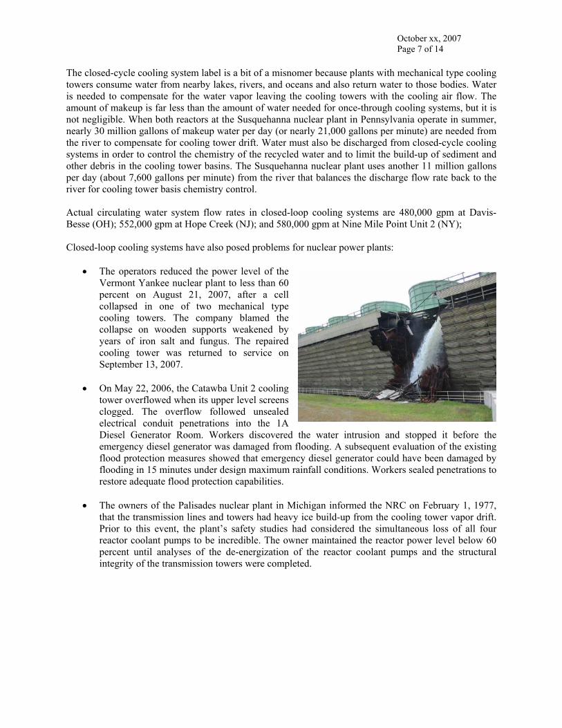
• The operators reduced the power level of the Vermont Yankee nuclear plant to less than 60 percent on August 21, 2007, after a cell collapsed in one of two mechanical type cooling towers. The company blamed the collapse on wooden supports weakened by years of iron salt and fungus. The repaired cooling tower was returned to service on September 13, 2007.
• On May 22, 2006, the Catawba Unit 2 cooling
tower overflowed when its upper level screens clogged. The overflow followed unsealed electrical conduit penetrations into the 1A Diesel Generator Room. Workers discovered the water intrusion and stopped it before the emergency diesel generator was damaged from flooding. A subsequent evaluation of the existing flood protection measures showed that emergency diesel generator could have been damaged by flooding in 15 minutes under design maximum rainfall conditions. Workers sealed penetrations to restore adequate flood protection capabilities.
• The owners of the Palisades nuclear plant in Michigan informed the NRC on February 1, 1977,
that the transmission lines and towers had heavy ice build-up from the cooling tower vapor drift. Prior to this event, the plant’s safety studies had considered the simultaneous loss of all four reactor coolant pumps to be incredible. The owner maintained the reactor power level below 60 percent until analyses of the de-energization of the reactor coolant pumps and the structural integrity of the transmission towers were completed.
October xx, 2007 Page 8 of 14
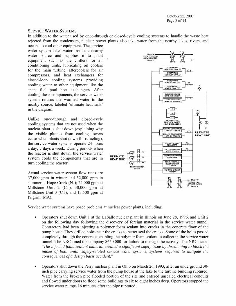
SSEERRVVIICCEE WWAATTEERR SSYYSSTTEEMMSS In addition to the water used by once-through or closed-cycle cooling systems to handle the waste heat rejected from the condensers, nuclear power plants also take water from the nearby lakes, rivers, and oceans to cool other equipment. The service water system takes water from the nearby water source and supplies it to plant equipment such as the chillers for air conditioning units, lubricating oil coolers for the main turbine, aftercoolers for air compressors, and heat exchangers for closed-loop cooling systems providing cooling water to other equipment like the spent fuel pool heat exchangers. After cooling these components, the service water system returns the warmed water to the nearby source, labeled ‘ultimate heat sink’ in the diagram. Unlike once-through and closed-cycle cooling systems that are not used when the nuclear plant is shut down (explaining why the visible plumes from cooling towers cease when plants shut down for refueling), the service water systems operate 24 hours a day, 7 days a week. During periods when the reactor is shut down, the service water system cools the components that are in turn cooling the reactor. Actual service water system flow rates are 37,000 gpm in winter and 52,000 gpm in summer at Hope Creek (NJ); 24,000 gpm at Millstone Unit 2 (CT); 30,000 gpm at Millstone Unit 3 (CT); and 13,500 gpm at Pilgrim (MA). Service water systems have posed problems at nuclear power plants, including:
• Operators shut down Unit 1 at the LaSalle nuclear plant in Illinois on June 28, 1996, and Unit 2 on the following day following the discovery of foreign material in the service water tunnel. Contractors had been injecting a polymer foam sealant into cracks in the concrete floor of the pump house. They drilled holes near the cracks to better seal the cracks. Some of the holes passed completely through the concrete, enabling the polymer foam sealant to collect in the service water tunnel. The NRC fined the company $650,000 for failure to manage the activity. The NRC stated “The injected foam sealant material created a significant safety issue by threatening to block the intake of both units’ safety-related service water systems, systems required to mitigate the consequences of a design basis accident.”
• Operators shut down the Perry nuclear plant in Ohio on March 26, 1993, after an underground 30-
inch pipe carrying service water from the pump house at the lake to the turbine building ruptured. Water from the broken pipe flooded portion of the site and entered unsealed electrical conduits and flowed under doors to flood some buildings to six to eight inches deep. Operators stopped the service water pumps 16 minutes after the pipe ruptured.
October xx, 2007 Page 9 of 14
• In November 1991, the NRC fined the owner of Millstone Unit 3 in Connecticut $50,000 for inadequate corrective actions after workers identified reduce service water flow but did not fix the problem until a test conducted to answer NRC’s questions demonstrated that emergency diesel generator B was getting only 15 percent of the cooling water flow it needed. Following this discovery, operators manually shut down Millstone Unit 3 on July 25, 1991, to disassemble and clean the service water system piping.
• A security officer responding to an alarm on the door to the service water tunnel discovered two
contract workers smoking marijuana. The workers were fired and escorted from the plant site.
• Workers entered the containment building at Indian Point Unit 2 in New York on October 17, 1980, to investigate a probable cause for an automatic reactor trip earlier that day. They discovered water on the containment floor – a lot of water. A small service water leak from components inside the containment collected over an extended period of time until the lower 9 feet of the reactor vessel was submerged. Approximately 100,000 gallons of water had leaked, undetected, over an undetermined period of time.
• Operators shut down the Unit 2 reactor at Arkansas Nuclear One on September 3, 1980, after the
NRC resident inspector identified the service water flow rate though the containment cooling units was less than that required by the technical specifications. Workers found that Asiatic clams caused extensive flow blockage of the service water system.
GGOOTT DDIILLUUTTIIOONN?? Nuclear power plants, whether using once-through cooling or closed-loop cooling, continuously discharge large amounts of water back into the nearby lake, river, or ocean. When leaks develop in the tubes within the condensers, the higher pressure of the lake, river, or ocean water within the tubes causes it to leak into the plant rather than radioactively contaminated liquid leaking out from the plant. But the water being discharged from nuclear plants often contains radioactivity. Nuclear power plants have systems – called liquid radwaste systems – that collect and treat radioactively contaminated water. The liquid radwaste systems have deminerlizer and filter units to treat the water. To the extent possible, the treated water gets recycled to the plant. At times, the liquid radwaste systems release the treated water to the nearby lake, river, or ocean. Such releases are controlled and monitored. The liquid radwaste system tank to be discharged is sampled to ascertain its radioactive contents (i.e., radioactive concentrations times the amount of water in the tank). If the radioactive contents are below federal limits on liquid releases, the water in the tank can be pumped into the discharge flow from the once-through or closed-loop cooling system. Mixing the liquid radwaste system release flow with the discharge flow dilutes the radioactivity concentration, which is further reduced when the discharge mixes with lake, river, or ocean water. Thus, when the water discharged from a nuclear power plant contains radioactivity, it is by design and not by accident.
October xx, 2007 Page 10 of 14
WWAATTEERR NNEEEEDDSS DDUURRIINNGG AACCCCIIDDEENNTT CCOONNDDIITTIIOONNSS The discussions above regarding once-through cooling systems, closed-loop cooling systems, and service water systems apply to water needs during normal operating conditions, the day-to-day process of making electricity. This section covers the water needs of a nuclear power plant in event of an accident. An accident at a nuclear power reactor reduces, but does not eliminate, the amount of cooling water needed by the plant. The reactor unit will no longer be generating electricity, so the tremendous volume of water needed by a once-through cooling system and the makeup volume of water needed to compensate for water vapor lost from a closed-loop cooling system are no longer required. It is additionally assumed that the reactor unit is disconnected from its electrical grid during the accident, so the volume of water needed by the service water systems for cooling of components normally used in day to day operations is also not needed. But what is needed during an accident is a volume of water to remove the heat still being generated by the reactor core and to cool emergency equipment and the rooms housing it. Three things are required: a source of water (called the Ultimate Heat Sink or UHS), two or more pumps to move water between the UHS and the plant, and a source of electricity for the motor-driven pumps.
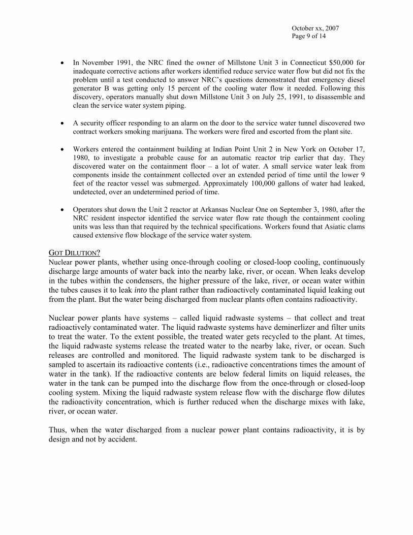
◄ The Limerick Generating Station in Pennsylvania uses two natural draft cooling towers (center) to remove heat during normal operation and a pond with water sprays (oval at upper left) as the UHS during accidents for the two reactors below the cooling towers.
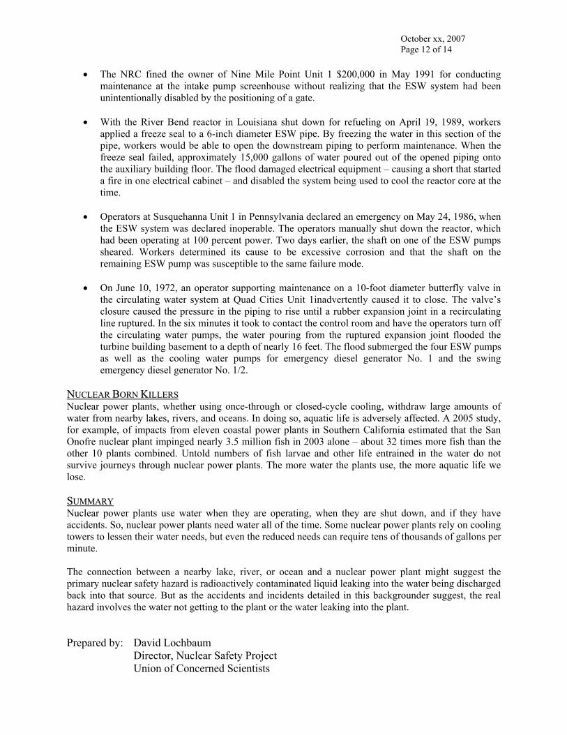
The Grand Gulf Nuclear Station in Mississippi uses a natural draft cooling tower during normal operation and mechanical type cooling towers (upper left) in event of an accident. ▼
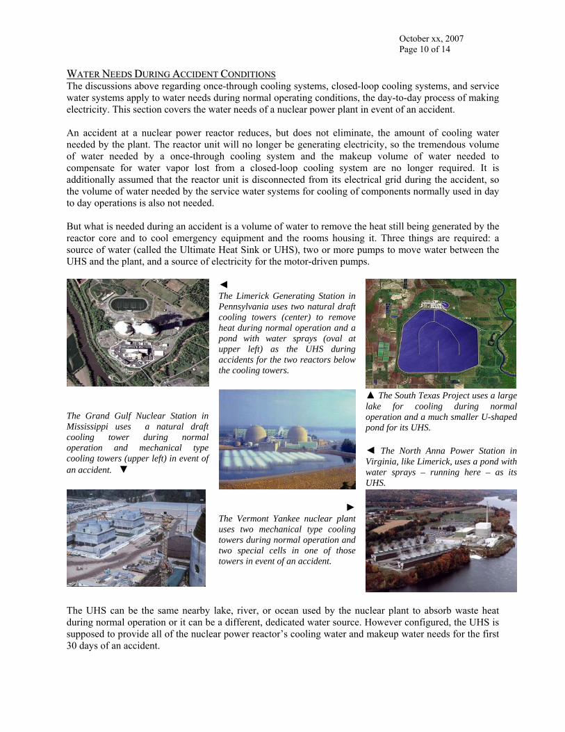
▲ The South Texas Project uses a large lake for cooling during normal operation and a much smaller U-shaped pond for its UHS. ◄ The North Anna Power Station in Virginia, like Limerick, uses a pond with water sprays – running here – as its UHS.
►
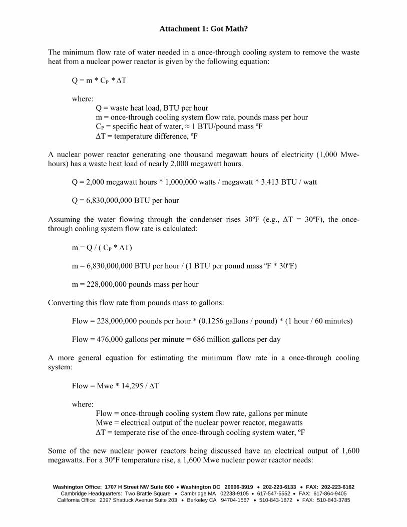
The Vermont Yankee nuclear plant uses two mechanical type cooling towers during normal operation and two special cells in one of those towers in event of an accident.
The UHS can be the same nearby lake, river, or ocean used by the nuclear plant to absorb waste heat during normal operation or it can be a different, dedicated water source. However configured, the UHS is supposed to provide all of the nuclear power reactor’s cooling water and makeup water needs for the first 30 days of an accident.

October xx, 2007 Page 11 of 14
Two or more pumps are used to take water from the UHS and supply it as cooling water or makeup water during the reactor. The schematic drawing to the left of the emergency service water (ESW) system for the Wolf Creek nuclear plant in Kansas represents the typical post-accident cooling system. ESW pump A to the upper right draws water from the UHS and provides cooling water to emergency components like the control room’s air conditioning condenser, the cooler for the emergency diesel generator, the containment air coolers, and the cooler for the safety injection pump room. After cooling these components, the water flows back to the UHS. ESW pump A can also provide makeup water to the component cooling water (CCW) system, the auxililary feedwater system, and/or the spent fuel pool (SFP) via the piping lines shown in the lower right corner. ESW pump B to the upper left mirrors the cooling and makeup water functions provided by ESW pump A for the redundant set of emergency components.
When a lake, river, or oceans serves as the UHS, the water needed by the ESW system during an accident are in the 10,000 to 30,000 gallons per minute range. Because the normal supply of electricity – backfeed from the electricity generated by the nuclear plant itself or power from the electrical grid – cannot be relied upon in event of an accident, nuclear power plants3 have emergency diesel generators (EDGs) onsite. The EDGs provide the electricity to emergency equipment during an accident, including the ESW pumps. The EDGs and the ESW pumps have a symbiotic relationship – most EDGs4 have their engines cooled by water supplied by the ESW pumps while the ESW pumps have their motors powered by electricity supplied by the EDGs. Nuclear plants have experienced ESW system problems, including:
• In January 2004, the NRC issued a White finding to the owner of the Perry nuclear plant in Ohio for allowing workers – twice – to reassembly ESW pump A improperly leading to its failures.
• The operators at the Ginna nuclear plant in New York reduced the reactor power level from 97
percent to 50 percent on January 20, 2004, because ice build-up on the intake structure’s screens partially blocked the in-flow of water from the lake. The water level in the intake structure – the source of water for the pumps – dropped nearly nine feet below normal. Had the water level dropped another foot, the ESW pumps would have been unable to supply water to emergency equipment and procedures would have guided operators into declaring a Site Area Emergency.
3 The exception to the rule being the Oconee nuclear plant in South Carolina which relies on backup power from the nearby Keowee hydroelectric dam. 4 The exception to the rule are a small handful of nuclear power plants with air-cooled EDGS.
October xx, 2007 Page 12 of 14
• The NRC fined the owner of Nine Mile Point Unit 1 $200,000 in May 1991 for conducting
maintenance at the intake pump screenhouse without realizing that the ESW system had been unintentionally disabled by the positioning of a gate.
• With the River Bend reactor in Louisiana shut down for refueling on April 19, 1989, workers
applied a freeze seal to a 6-inch diameter ESW pipe. By freezing the water in this section of the pipe, workers would be able to open the downstream piping to perform maintenance. When the freeze seal failed, approximately 15,000 gallons of water poured out of the opened piping onto the auxiliary building floor. The flood damaged electrical equipment – causing a short that started a fire in one electrical cabinet – and disabled the system being used to cool the reactor core at the time.
• Operators at Susquehanna Unit 1 in Pennsylvania declared an emergency on May 24, 1986, when
the ESW system was declared inoperable. The operators manually shut down the reactor, which had been operating at 100 percent power. Two days earlier, the shaft on one of the ESW pumps sheared. Workers determined its cause to be excessive corrosion and that the shaft on the remaining ESW pump was susceptible to the same failure mode.
• On June 10, 1972, an operator supporting maintenance on a 10-foot diameter butterfly valve in
the circulating water system at Quad Cities Unit 1inadvertently caused it to close. The valve’s closure caused the pressure in the piping to rise until a rubber expansion joint in a recirculating line ruptured. In the six minutes it took to contact the control room and have the operators turn off the circulating water pumps, the water pouring from the ruptured expansion joint flooded the turbine building basement to a depth of nearly 16 feet. The flood submerged the four ESW pumps as well as the cooling water pumps for emergency diesel generator No. 1 and the swing emergency diesel generator No. 1/2.
NNUUCCLLEEAARR BBOORRNN KKIILLLLEERRSS Nuclear power plants, whether using once-through or closed-cycle cooling, withdraw large amounts of water from nearby lakes, rivers, and oceans. In doing so, aquatic life is adversely affected. A 2005 study, for example, of impacts from eleven coastal power plants in Southern California estimated that the San Onofre nuclear plant impinged nearly 3.5 million fish in 2003 alone – about 32 times more fish than the other 10 plants combined. Untold numbers of fish larvae and other life entrained in the water do not survive journeys through nuclear power plants. The more water the plants use, the more aquatic life we lose. SSUUMMMMAARRYY Nuclear power plants use water when they are operating, when they are shut down, and if they have accidents. So, nuclear power plants need water all of the time. Some nuclear power plants rely on cooling towers to lessen their water needs, but even the reduced needs can require tens of thousands of gallons per minute. The connection between a nearby lake, river, or ocean and a nuclear power plant might suggest the primary nuclear safety hazard is radioactively contaminated liquid leaking into the water being discharged back into that source. But as the accidents and incidents detailed in this backgrounder suggest, the real hazard involves the water not getting to the plant or the water leaking into the plant. Prepared by: David Lochbaum Director, Nuclear Safety Project Union of Concerned Scientists
Attachment 1: Got Math?
Washington Office: 1707 H Street NW Suite 600 • Washington DC 20006-3919 • 202-223-6133 • FAX: 202-223-6162
Cambridge Headquarters: Two Brattle Square • Cambridge MA 02238-9105 • 617-547-5552 • FAX: 617-864-9405 California Office: 2397 Shattuck Avenue Suite 203 • Berkeley CA 94704-1567 • 510-843-1872 • FAX: 510-843-3785
The minimum flow rate of water needed in a once-through cooling system to remove the waste heat from a nuclear power reactor is given by the following equation:
Q = m * CP * ΔT where: Q = waste heat load, BTU per hour m = once-through cooling system flow rate, pounds mass per hour CP = specific heat of water, ≈ 1 BTU/pound mass ºF ΔT = temperature difference, ºF
A nuclear power reactor generating one thousand megawatt hours of electricity (1,000 Mwe-hours) has a waste heat load of nearly 2,000 megawatt hours. Q = 2,000 megawatt hours * 1,000,000 watts / megawatt * 3.413 BTU / watt Q = 6,830,000,000 BTU per hour Assuming the water flowing through the condenser rises 30ºF (e.g., ΔT = 30ºF), the once-through cooling system flow rate is calculated: m = Q / ( CP * ΔT) m = 6,830,000,000 BTU per hour / (1 BTU per pound mass ºF * 30ºF) m = 228,000,000 pounds mass per hour Converting this flow rate from pounds mass to gallons: Flow = 228,000,000 pounds per hour * (0.1256 gallons / pound) * (1 hour / 60 minutes) Flow = 476,000 gallons per minute = 686 million gallons per day A more general equation for estimating the minimum flow rate in a once-through cooling system: Flow = Mwe * 14,295 / ΔT where: Flow = once-through cooling system flow rate, gallons per minute Mwe = electrical output of the nuclear power reactor, megawatts ΔT = temperate rise of the once-through cooling system water, ºF Some of the new nuclear power reactors being discussed have an electrical output of 1,600 megawatts. For a 30ºF temperature rise, a 1,600 Mwe nuclear power reactor needs:
October xx, 2007 Page 14 of 14
Flow = 1,600 Mwe * 14,295 / 30ºF = 762,384 gallons per minute Unless the nearby source of water is an ocean, large river, or large lake, it may be incapable of absorbing all of the waste heat being rejected by a nuclear plant using a once-through cooling system. The equation, slightly modified, can be used to assess the potential impact of once-through cooling on a river.
Q = m * CP * ΔT where: Q = waste heat load, BTU per hour m = river flow rate, pounds mass per hour CP = specific heat of water, ≈ 1 BTU/pound mass ºF ΔT = temperature difference, ºF
Taking the waste heat rejected from that 1,000 Mwe nuclear power reactor (6,830,000,000 BTU per hour) and assuming that the thermal pollution discharge cannot cause the river water temperature to rise more than 5ºF, the equation can be rearranged to determine the minimum river flow rate: m = Q / (CP * ΔT) m = 6,830,000,000 BTU per hour / (1 BTU per pound mass ºF * 5ºF) m = 1,370,000,000 pounds mass per hour Converting this flow rate to cubic feet per second (cfs), a more conventional river flow measure: cfs = 1,370,000,000 pounds mass / hour * (1ft3 / 62.4 pounds) * (1 hour / 3600 seconds) cfs = 6,077 cubic feet per second The U.S. Geological Service maintains an online National Water Information Service at HHTTTTPP::////WWAATTEERRDDAATTAA..UUSSGGSS..GGOOVV//NNWWIISS//RRTT that provide real time reporting of river flow rates. For example, the USA Streamflow Table on November 2, 2007, reported results from 8,428 monitoring locations across the country. The results show that only one – the Pamlico River near Washington, NC at 7,920 cfs – of several dozen monitored locations in North Carolina had a flow rate exceeding 6,077 cfs.