Embed Size (px)
Citation preview

Primary funding is provided by
The SPE Foundation through member donations
and a contribution from Offshore Europe
The Society is grateful to those companies that allow their
professionals to serve as lecturers
Additional support provided by American Institute for Mechanical
Engineers (AIME)
Society of Petroleum Engineers
Distinguished Lecturer Program www.spe.org/dl
1

This program year (2011-2012) marks the 50th anniversary of the SPE
Distinguished Lecturer program. Please visit our site to learn more
about this amazing program.www.spe.org/go/DL50
2

Practical Approach to Solving
Wellbore Instability Problems
Samuel O. Osisanya, Ph.D.; P.E.
Professor
Mewbourne School of Petroleum and Geol. Engineering
The University of Oklahoma
Norman, OK, USA
Society of Petroleum Engineers
Distinguished Lecturer Program www.spe.org/dl 3
Outline ● Introduction & Objectives
● Causes of Wellbore Instability
● Wellbore Stability (WS)
– Before Drilling; While Drilling; &
After Drilling
● Symptoms, Prevention &
Remedial Actions
● Case Studies
● Summary & Conclusions
4

Introduction
5
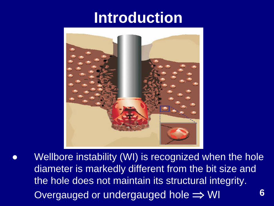
Introduction
● Wellbore instability (WI) is recognized when the hole
diameter is markedly different from the bit size and
the hole does not maintain its structural integrity.
Overgauged or undergauged hole WI
6
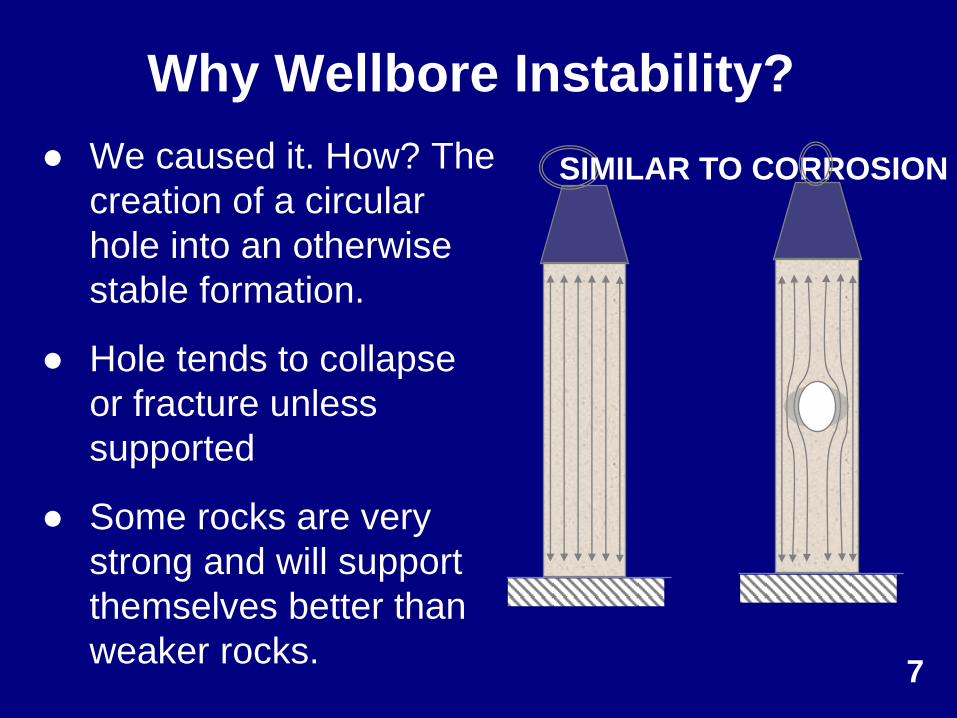
Why Wellbore Instability?
SIMILAR TO CORROSION ● We caused it. How? The
creation of a circular
hole into an otherwise
stable formation.
● Hole tends to collapse
or fracture unless
supported
● Some rocks are very
strong and will support
themselves better than
weaker rocks. 7
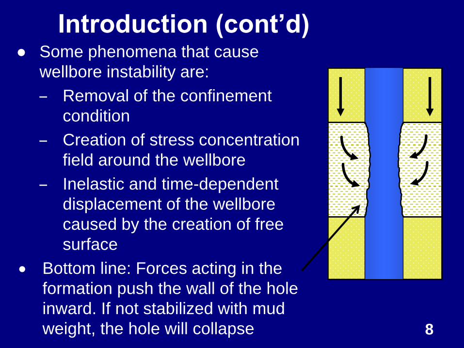
Introduction (cont’d) ● Some phenomena that cause
wellbore instability are:
– Removal of the confinement
condition
– Creation of stress concentration
field around the wellbore
– Inelastic and time-dependent
displacement of the wellbore
caused by the creation of free
surface
Bottom line: Forces acting in the
formation push the wall of the hole
inward. If not stabilized with mud
weight, the hole will collapse 8
Consequences of Wellbore Instability
● These are:
– At least reduced drilling performance and/or
stuck BHA & downhole tools fishing
– Loss of equipment and sidetracking
– Excessive trip time and reaming time
– Poor hole logging; inability to land casing; and
poor cementing conditions/jobs
– At worst it can lead to total collapse and loss of
the hole
● Bottom Line: increase in non-productive
time and increase in total drilling cost. 9
Objectives
1. To describe causes of wellbore
instability problems
2. To describe wellbore stability before,
during, and after drilling wells
3. To describe symptoms of the
problems while drilling
4. To discuss practical, preventive, and
remedial actions for wellbore instability
10

Causes of Wellbore Instability
11
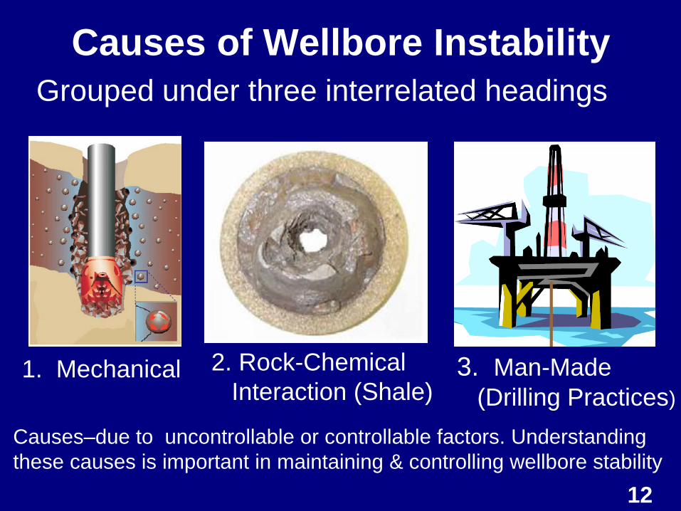
Causes of Wellbore Instability
1. Mechanical 2. Rock-Chemical
Interaction (Shale) 3. Man-Made
(Drilling Practices)
Grouped under three interrelated headings
Causes–due to uncontrollable or controllable factors. Understanding
these causes is important in maintaining & controlling wellbore stability
12
1. Mechanical Wellbore Instability
● Key parameters are:
1. Rock Stresses/Rock Types
2. Rock Strength (weaken)
3. Wellbore Geometry (Hole
Inclination & Azimuth)
4. Man-Made Related Stresses
● First two are uncontrollable and the
last two are controllable 13
Mechanical Wellbore Instability ● Mechanical failure occurs when
wellbore stress concentrations
exceed the rock strength
● Wellbore stress concentrations result
from
– Drilling into pre-stressed rock (earth
stresses)
– Excessive wellbore pressures
– Drillstring vibrations 14
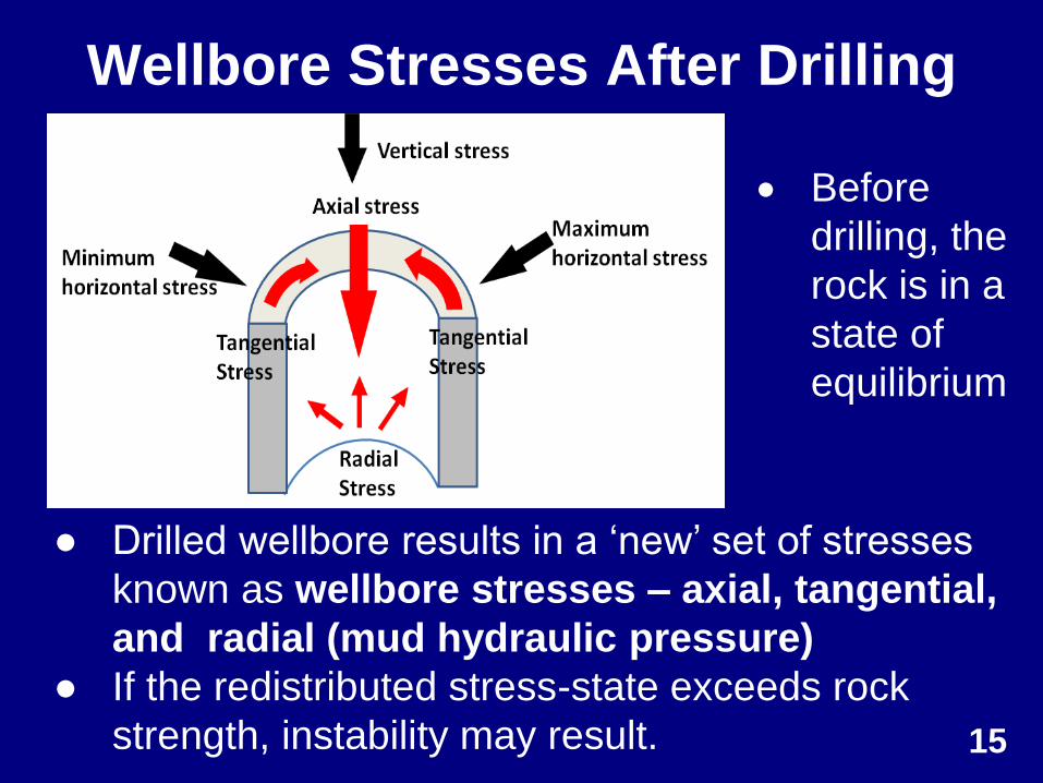
Wellbore Stresses After Drilling
● Drilled wellbore results in a ‘new’ set of stresses
known as wellbore stresses – axial, tangential,
and radial (mud hydraulic pressure)
● If the redistributed stress-state exceeds rock
strength, instability may result. 15
Before
drilling, the
rock is in a
state of
equilibrium
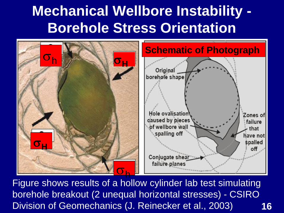
Mechanical Wellbore Instability -
Borehole Stress Orientation
Figure shows results of a hollow cylinder lab test simulating
borehole breakout (2 unequal horizontal stresses) - CSIRO
Division of Geomechanics (J. Reinecker et al., 2003) 16
H
H
h
h Schematic of Photograph
● Sedimentary rocks in general are shales (75%)
and in particular they are sensitive to their
chemical environment.
● Reaction between the shale and drilling fluid
causes the shale to swell, weaken, and
eventually fall/collapse into the wellbore.
● Solution is to have a drilling fluid system that
balances the mechanical and chemical forces.
● Also use drilling practices that minimize shale or
formation instability. 17
2. Rock-Chemical Interaction (Shale)
Instability
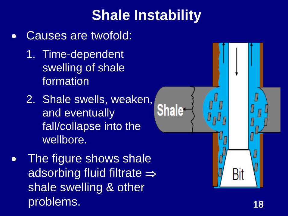
Shale Instability
Causes are twofold:
1. Time-dependent
swelling of shale
formation
2. Shale swells, weaken,
and eventually
fall/collapse into the
wellbore.
The figure shows shale
adsorbing fluid filtrate
shale swelling & other
problems. 18
Shale Hydration Mechanism
19
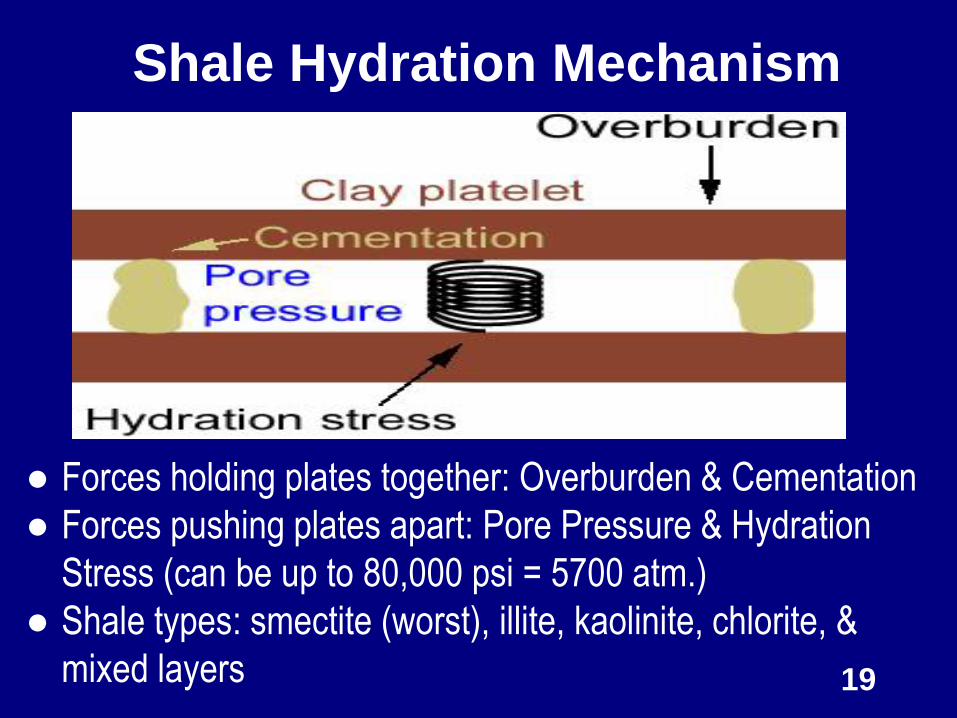
● Forces holding plates together: Overburden & Cementation
● Forces pushing plates apart: Pore Pressure & Hydration
Stress (can be up to 80,000 psi = 5700 atm.)
● Shale types: smectite (worst), illite, kaolinite, chlorite, &
mixed layers
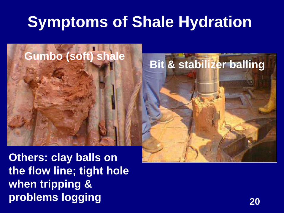
Symptoms of Shale Hydration
Gumbo (soft) shale
20
Bit & stabilizer balling
Others: clay balls on
the flow line; tight hole
when tripping &
problems logging
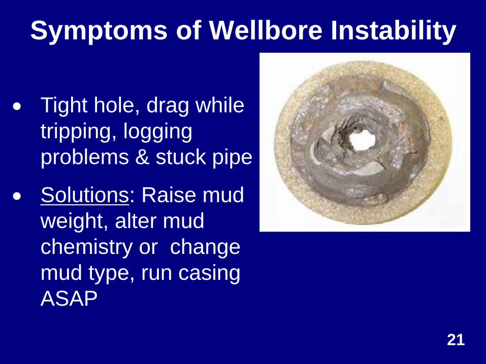
Symptoms of Wellbore Instability
Tight hole, drag while
tripping, logging
problems & stuck pipe
Solutions: Raise mud
weight, alter mud
chemistry or change
mud type, run casing
ASAP
21
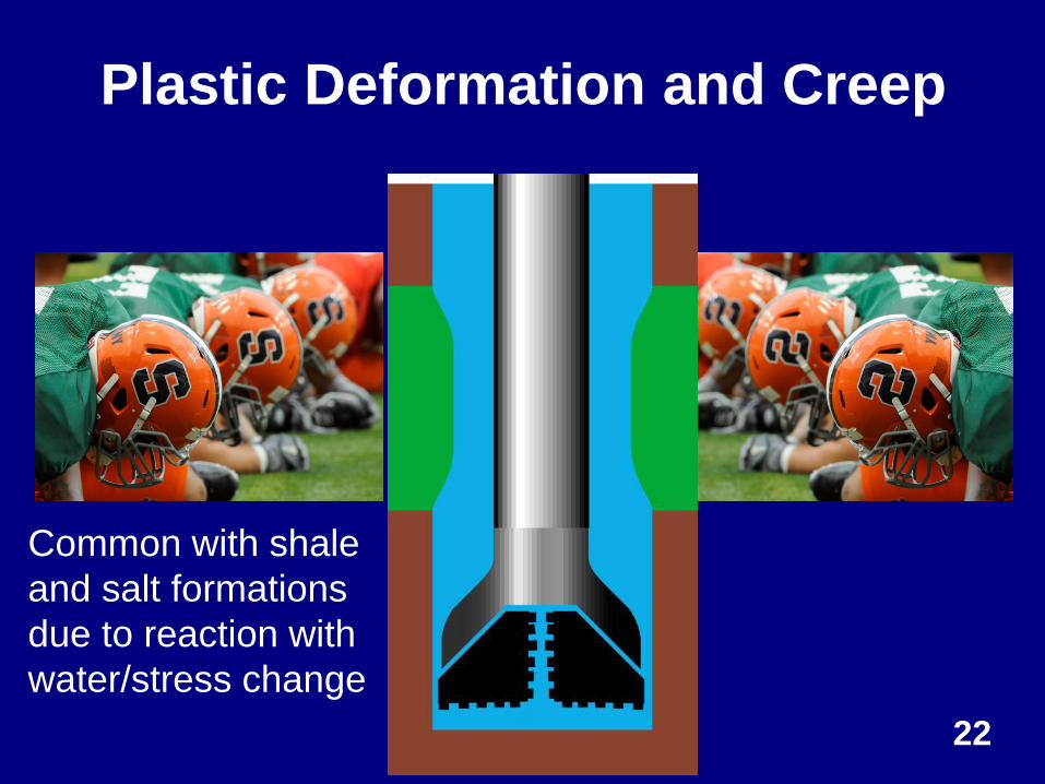
Plastic Deformation and Creep
22
Common with shale
and salt formations
due to reaction with
water/stress change
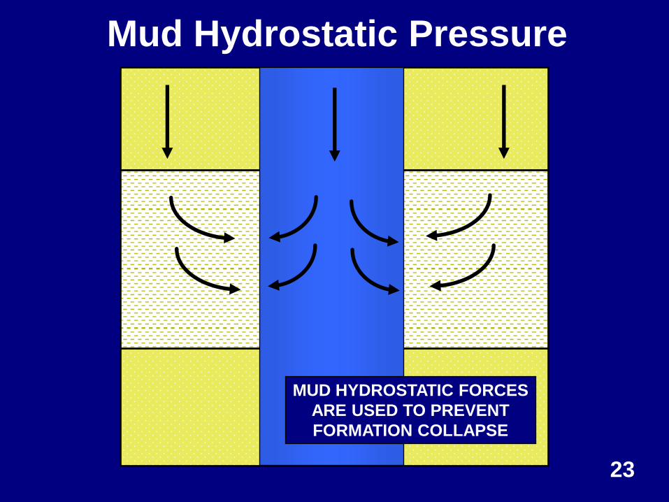
MUD HYDROSTATIC FORCES
ARE USED TO PREVENT
FORMATION COLLAPSE
Mud Hydrostatic Pressure
23
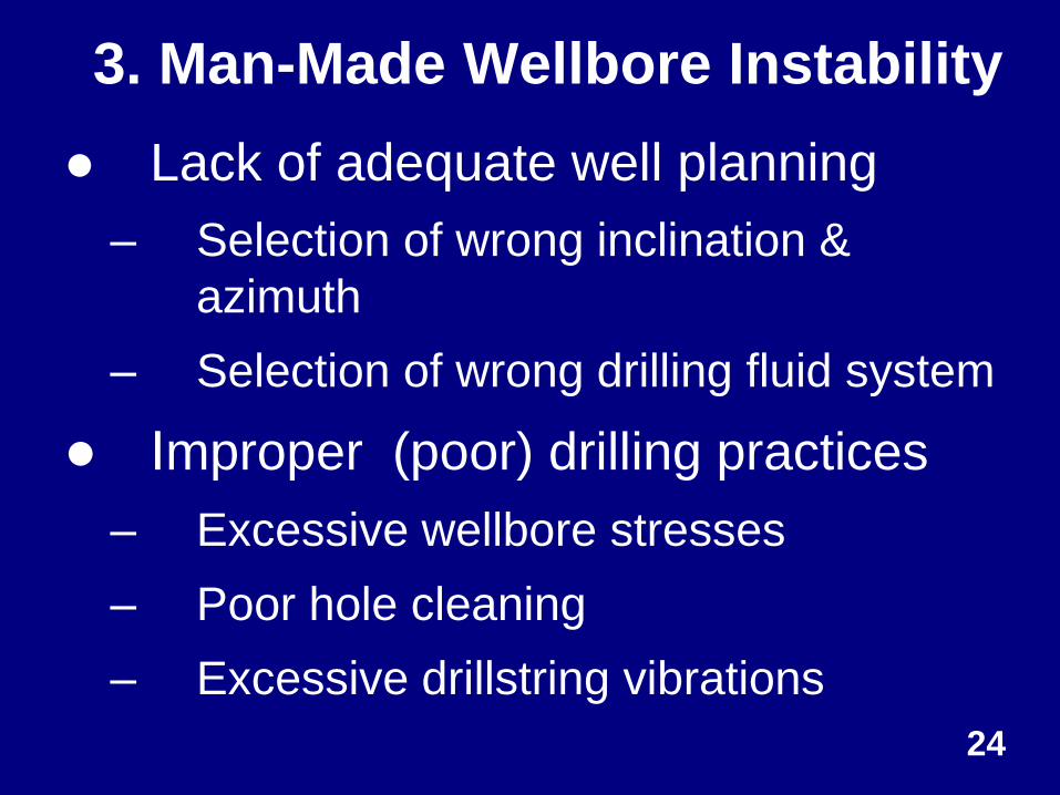
● Lack of adequate well planning
– Selection of wrong inclination &
azimuth
– Selection of wrong drilling fluid system
● Improper (poor) drilling practices
– Excessive wellbore stresses
– Poor hole cleaning
– Excessive drillstring vibrations
3. Man-Made Wellbore Instability
24
Wellbore Stability (WS)
Before Drilling (Planning)
25
Wellbore Stability (WS) Before Drilling
(Planning)
● Involves: geo-mechanics and drilling
fluid selection
– A comprehensive GeoMechanics study is
essential in order to understand causes
of wellbore instability and to improve
drilling design and drilling performance.
• Extremely important for horizontal &
extended reach wells.
– An extensive shale inhibition testing
program is also essential. 26
Wellbore Stability (WS) Before Drilling
(Planning)
● Steps for GeoMechanics study are:
– To acquire, audit & perform quality control
of geomechanical data (e.g. wireline logs)
– To build Mechanical Earth Model (MEM)
– To perform WS analysis of the planned well
including trajectory sensitivity analysis
– To review wellbore instability drilling events
from offset wells
– To forecast wellbore stability 27
Wellbore Stability Before Drilling
(Planning) ● Geo-Mechanical Earth Model
– Integrate all geo-mechanical data
available from a field/basin into one
“database”
– Use model to predict wellbore instability
problems in an upcoming well
– Model outputs – (1) safe mud weight
window and (2) safest inclination &
azimuth to drill. 28
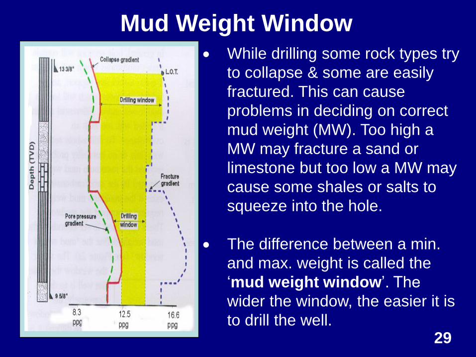
Mud Weight Window
29
While drilling some rock types try
to collapse & some are easily
fractured. This can cause
problems in deciding on correct
mud weight (MW). Too high a
MW may fracture a sand or
limestone but too low a MW may
cause some shales or salts to
squeeze into the hole.
The difference between a min.
and max. weight is called the
‘mud weight window’. The
wider the window, the easier it is
to drill the well.
Shale Inhibition Test Methods
● Wellbore Simulators - swelling
stress/strain tests under HTHP (lab)
– to model fluid flow in shale (shale
permeability)
● Cuttings Dispersion - evaluation of
mud type (lab & rig site)
● Cation Exchange Capacity (aka
MBT) – use to determine shale type
30
Wellbore Instability While
Drilling – Improper Drilling
Practices
31
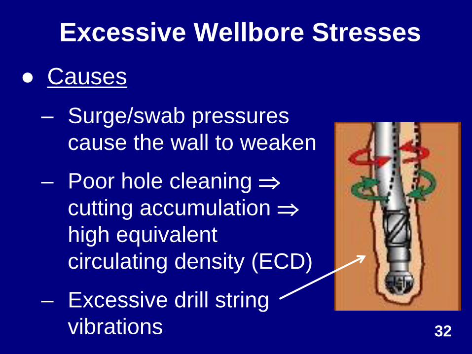
Excessive Wellbore Stresses
● Causes
– Surge/swab pressures
cause the wall to weaken
– Poor hole cleaning
cutting accumulation
high equivalent
circulating density (ECD)
– Excessive drill string
vibrations 32
RUNNING IN
PULLING OUT
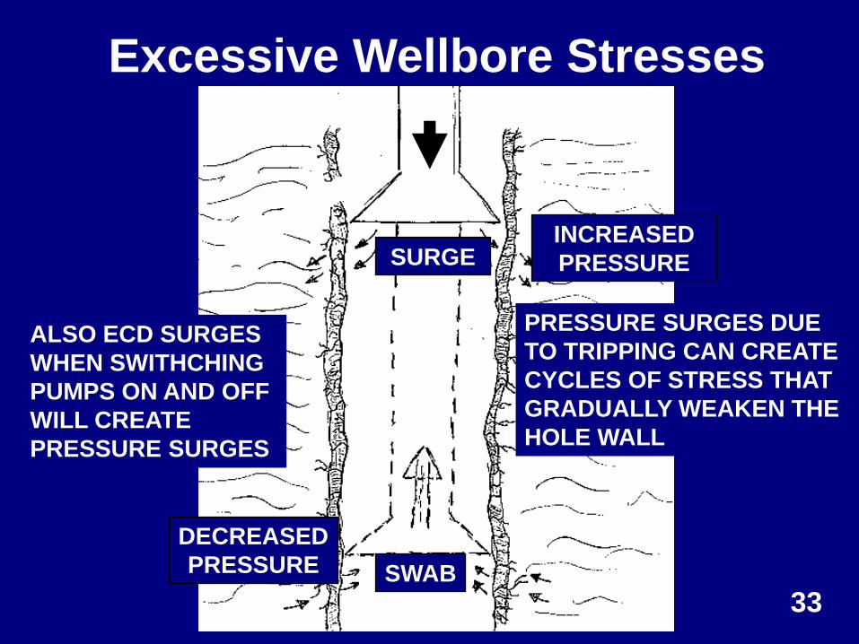
INCREASED
PRESSURE
DECREASED
PRESSURE
PRESSURE SURGES DUE
TO TRIPPING CAN CREATE
CYCLES OF STRESS THAT
GRADUALLY WEAKEN THE
HOLE WALL
Excessive Wellbore Stresses
33
ALSO ECD SURGES
WHEN SWITHCHING
PUMPS ON AND OFF
WILL CREATE
PRESSURE SURGES
SURGE
SWAB
34
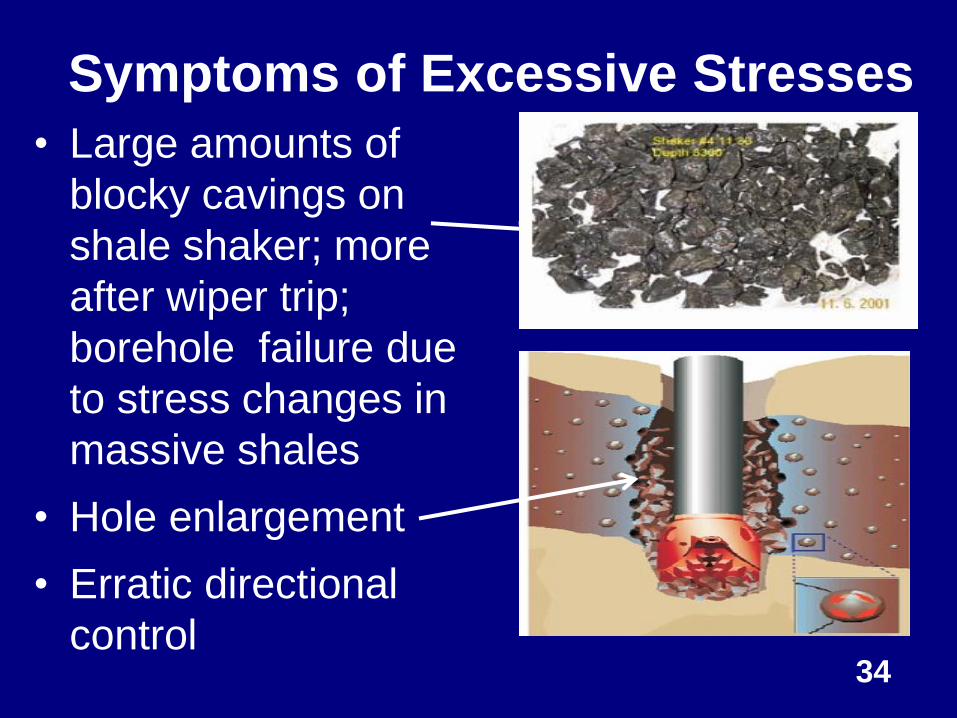
Symptoms of Excessive Stresses
• Large amounts of
blocky cavings on
shale shaker; more
after wiper trip;
borehole failure due
to stress changes in
massive shales
• Hole enlargement
• Erratic directional
control
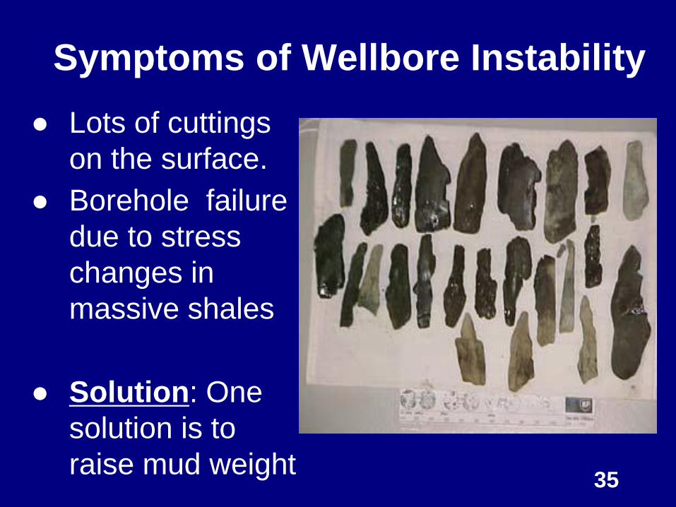
Symptoms of Wellbore Instability
● Lots of cuttings
on the surface.
● Borehole failure
due to stress
changes in
massive shales
● Solution: One
solution is to
raise mud weight 35
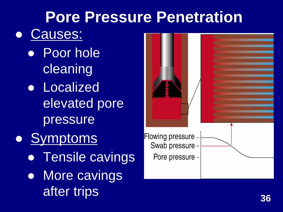
Pore Pressure Penetration ● Causes:
● Poor hole
cleaning
● Localized
elevated pore
pressure
● Symptoms
● Tensile cavings
● More cavings
after trips 36
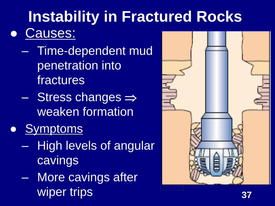
Instability in Fractured Rocks
37
● Causes:
– Time-dependent mud
penetration into
fractures
– Stress changes
weaken formation
● Symptoms
– High levels of angular
cavings
– More cavings after
wiper trips
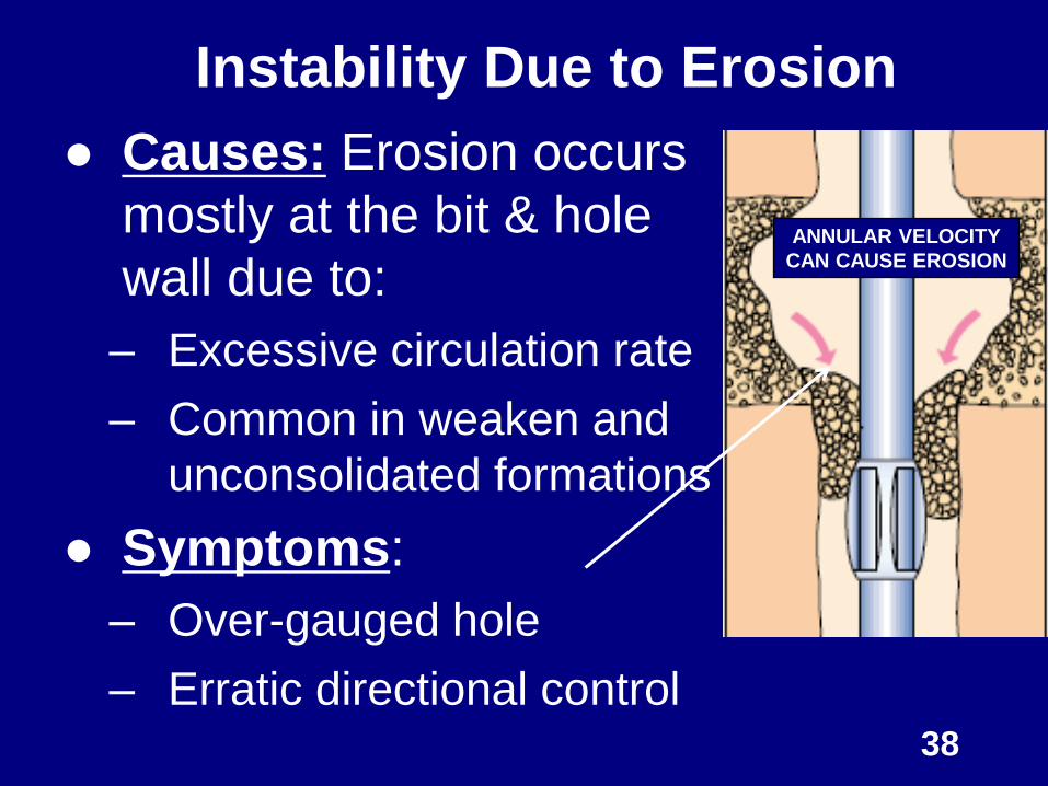
Instability Due to Erosion
● Causes: Erosion occurs
mostly at the bit & hole
wall due to:
– Excessive circulation rate
– Common in weaken and
unconsolidated formations
● Symptoms:
– Over-gauged hole
– Erratic directional control 38
ANNULAR VELOCITY
CAN CAUSE EROSION
Wellbore Stability While Drilling
● Involves real time WS management
(control): This is a 2-fold process:
1. Continuous monitoring – caving
analysis, downhole measurements
(MWD and LWD) and surface
signatures to diagnose onset of a
problem
2. Remedial actions – involve control of
surface parameters such as WOB,
mud weight, flow rate, etc. 39
Wellbore Stability While Drilling
● Caving Analysis: A key parameter
to managing wellbore instability in
real time; provides an early
warning of wellbore instability
– Monitor caving rate
– Perform caving morphology
1. Types of cavings: Tabular,
Angular, or Splintered
40
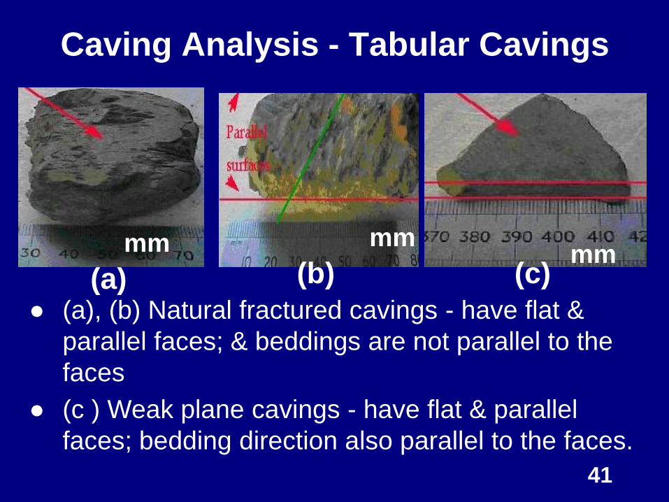
Caving Analysis - Tabular Cavings
● (a), (b) Natural fractured cavings - have flat &
parallel faces; & beddings are not parallel to the
faces
● (c ) Weak plane cavings - have flat & parallel
faces; bedding direction also parallel to the faces.
41
(b) (a) (c) mm mm
mm
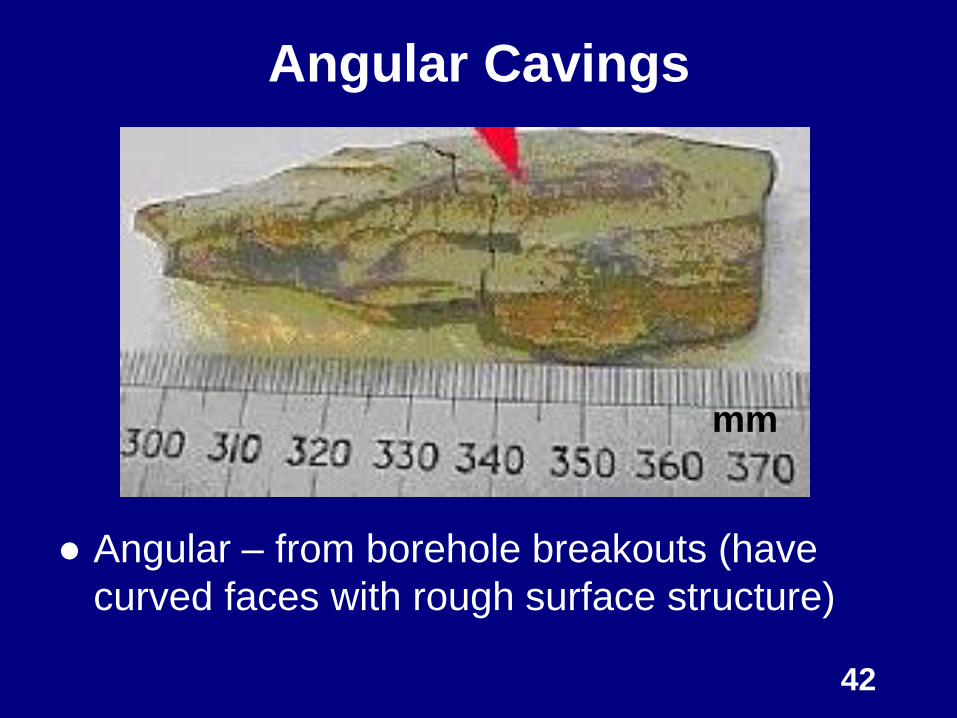
Angular Cavings
● Angular – from borehole breakouts (have
curved faces with rough surface structure)
42
mm
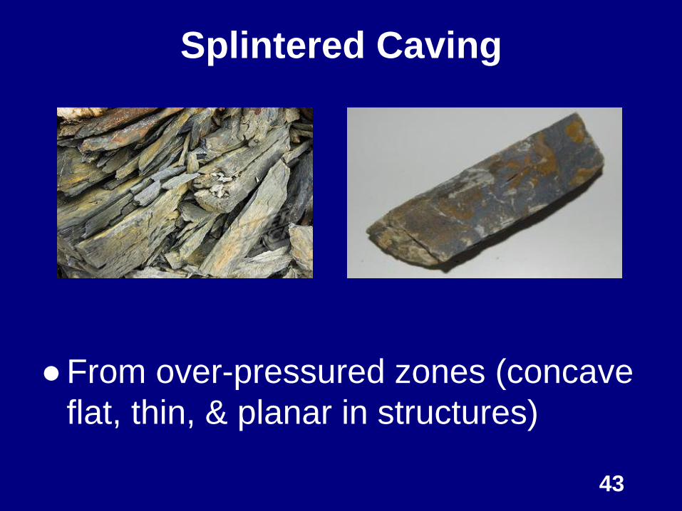
Splintered Caving
● From over-pressured zones (concave
flat, thin, & planar in structures)
43
Downhole & Surface Measurements
● Run tools to monitor annular
pressures (APWD), hole diameter
(caliper log), & downhole vibrations
to diagnose onset of a problem
● Control surface parameters (WOB,
RPM, flow rate, mud weight, &
rheology) to fix a failed or failing
wellbore.
44
Remedial Actions While
Drilling
45
Remedial Actions for Wellbore
Instability
● Depend on type of instability and its
severity
● Involve integration of the three
causes: mechanical, rock-chemical
interaction, & man-made instabilities
– May be problematic in some cases.
Why? Rocks are not identical
46
ROP and hole cleaning efficiency.
– Continuously monitor cavings (analysis)
– Monitor hole cleaning & reduce ROP if
necessary
– Control surface parameters
Improve drilling practices: trip wisely (1
stand/minute) & minimize wiper trips
If everything fail, case the well ASAP
Remedial Actions for Wellbore
Instability
47
Wellbore Stability After
Drilling
48
● This is Post-Drilling Review. Involves
– Acquiring relevant geomechanical
data, analyzing same and updating
Mechanical Earth Model (MEM)
– Reviewing all drilling events leading
to wellbore instability
– Reviewing planned WS action with
actual performance, and analyze
differences 49
Wellbore Stability After Drilling
● Development of New Drilling
Fluid Systems
● Use of Annular Pressure While
Drilling Tools
● Use of Rotary Steerable Systems
● Monitoring of Downhole
Vibrations
50
New Developments for Solving
Wellbore Instability Problems
● Various synthetic water-based mud
are being developed – to match the
performance of oil-based mud
● Addition of coating/plugging materials
– Silicates
– Methyl Glycoside
– Mixed-Metal-Hydroxide (MMH)
51
Development of New Drilling Fluid
Systems
● The principle value of a rotary
steerable system (RSS) is to allow
continuous rotation while steering.
Major benefits are:
– Improved drilling efficiency
– Optimized hole quality (gauged and
smooth well path)
– Reduced risk of stuck pipe 52
Use of Rotary Steerable Systems
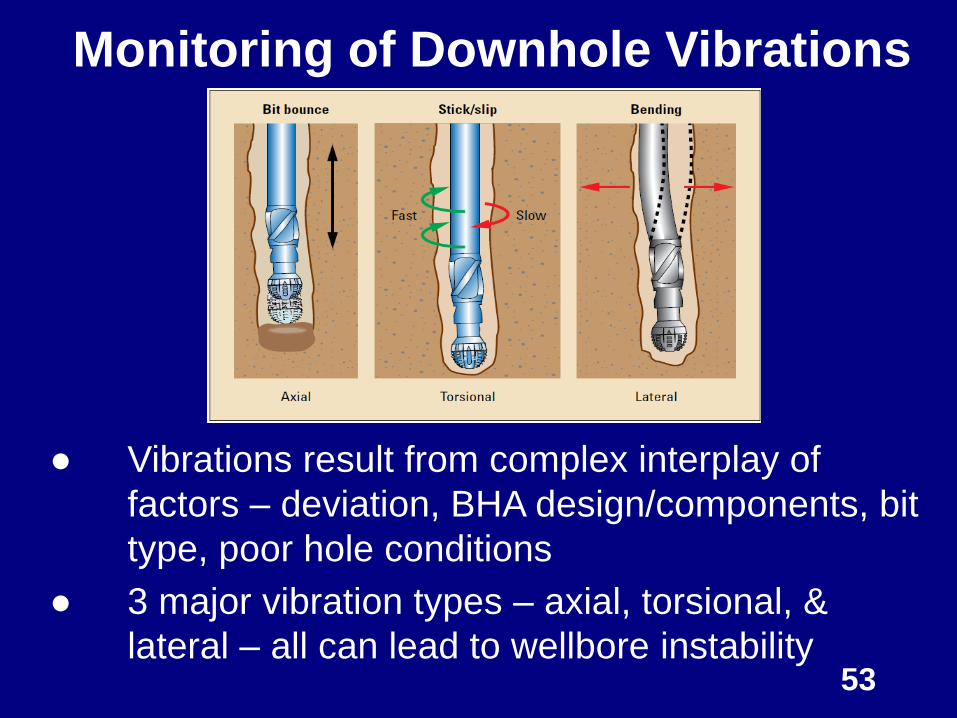
● Vibrations result from complex interplay of
factors – deviation, BHA design/components, bit
type, poor hole conditions
● 3 major vibration types – axial, torsional, &
lateral – all can lead to wellbore instability 53
Monitoring of Downhole Vibrations
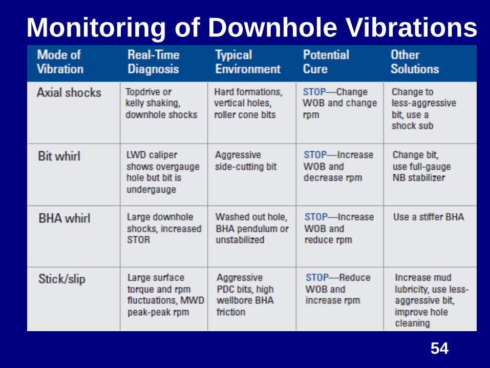
54
Monitoring of Downhole Vibrations

Case Studies
55
56
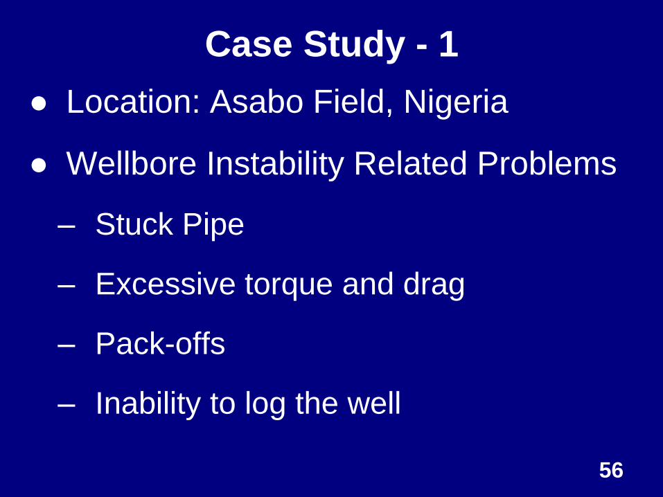
Case Study - 1
● Location: Asabo Field, Nigeria
● Wellbore Instability Related Problems
– Stuck Pipe
– Excessive torque and drag
– Pack-offs
– Inability to log the well
57
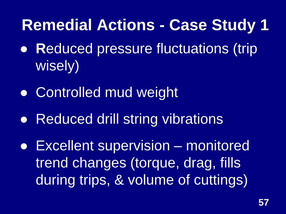
Remedial Actions - Case Study 1
● Reduced pressure fluctuations (trip
wisely)
● Controlled mud weight
● Reduced drill string vibrations
● Excellent supervision – monitored
trend changes (torque, drag, fills
during trips, & volume of cuttings)
58
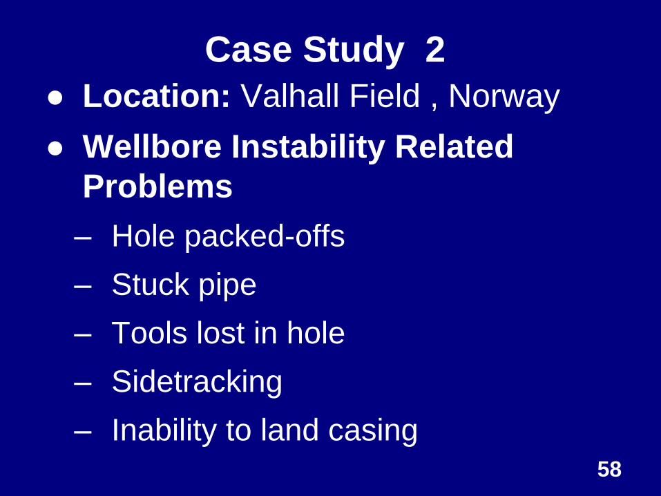
Case Study 2
● Location: Valhall Field , Norway
● Wellbore Instability Related
Problems
– Hole packed-offs
– Stuck pipe
– Tools lost in hole
– Sidetracking
– Inability to land casing
59
Remedial Actions - Case Study 2
● Used Integrated Approach
–Constructed geomechanical earth
model
–Monitored drilling data, acquired
more data, & updated model
–Interpreted observations
–Changed hole inclination and
azimuth

Summary and Conclusions
60

Remember!
Although we can’t control what the
drillers do, we can influence them
and gain credibility with them by
understanding their problems,
speaking their language, and letting
them understand the consequences
of their actions.
61
Summary
● Combined analysis (integrated
approach) of wellbore stresses,
mud chemistry, and excellent
drilling practices is the key to
minimizing wellbore instability
● With adequate planning and
supervision the problems can be
solved if not totally eliminated.
62
63
Summary Total prevention of wellbore instability is unrealistic.
Wellbore wants to collapse
Three main causes of wellbore instability:
Mechanical; Chemical; Drilling Practices
Prevent pressure surges/swabs
Maintain correct mud weight (Increase mud weight at
higher hole angles)
Minimize time hole is open
Maintain good mud inhibition
Warning signs: Torque & drag increase; Ledges; Bit
balling; Soft cuttings; More caving; Increased mud
viscosity and low gravity solids
Conclusions Before Drilling
1. Mechanical Earth Model must be utilized to
predict wellbore instability problems in an
upcoming well.
2. We must anticipate remedial actions to be used,
which depend on type of instability and its
severity
While Drilling
3. We must employ the best drilling practices (e.g.
reduction of surge/swab pressures and drillstring
vibrations) as well as excellent mud chemistry
64
Conclusions While Drilling
4. ROP and hole cleaning efficiency form the key
links between wellbore instability and
operations. Hence, we must optimize hole
cleaning and minimize open hole time
5. Must perform continuous caving analysis and
control surface parameters
After Drilling
6. Perform Post-Drilling Review – collect data and
update MEM); detail wellbore instability events
Key words – Planning, Teamwork & Excellent
Drilling Practices/Supervision 65

I would like to thanks to the following:
● SPE Distinguished Lecturer Program
Committee Members for this
opportunity and my many mentors
over the years
● Mewbourne School of Petroleum and
Geological Engineering, The
University of Oklahoma for
permission to take part in this
important event 66


