Embed Size (px)
Citation preview
9/13/18
1
1
A CHIMERA GRID TOOLS TUTORIAL
William M. Chan
NASA Ames Research Center
14th Symposium on Overset Composite Grids and Solution Technology, College Park, Maryland, October 1-4, 2018
2
OVERVIEW
- Introduction
- Pre-processing
- Post-processing
- New features in version 2.2
3
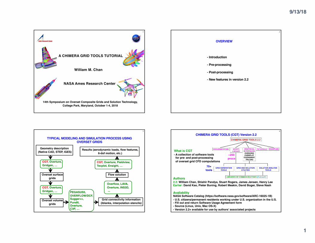
TYPICAL MODELING AND SIMULATION PROCESS USING OVERSET GRIDS
Geometry description(Native CAD, STEP, IGES)
Overset volume grids
Overset surface grids
Results (aerodynamic loads, flow features, 6-dof motion, etc.)
Flow solution
Grid connectivity information (iblanks, interpolation stencils)
CGT, Overture, Gridgen, …
PEGASUS5, OVERFLOW/DCF, Suggar++, Pundit,Overture,C3P, …
Overflow, LAVA, Overture, INS3D,...
CGT, Overture, Fieldview, Tecplot, Ensight, …
CGT, Overture, Gridgen, …
4
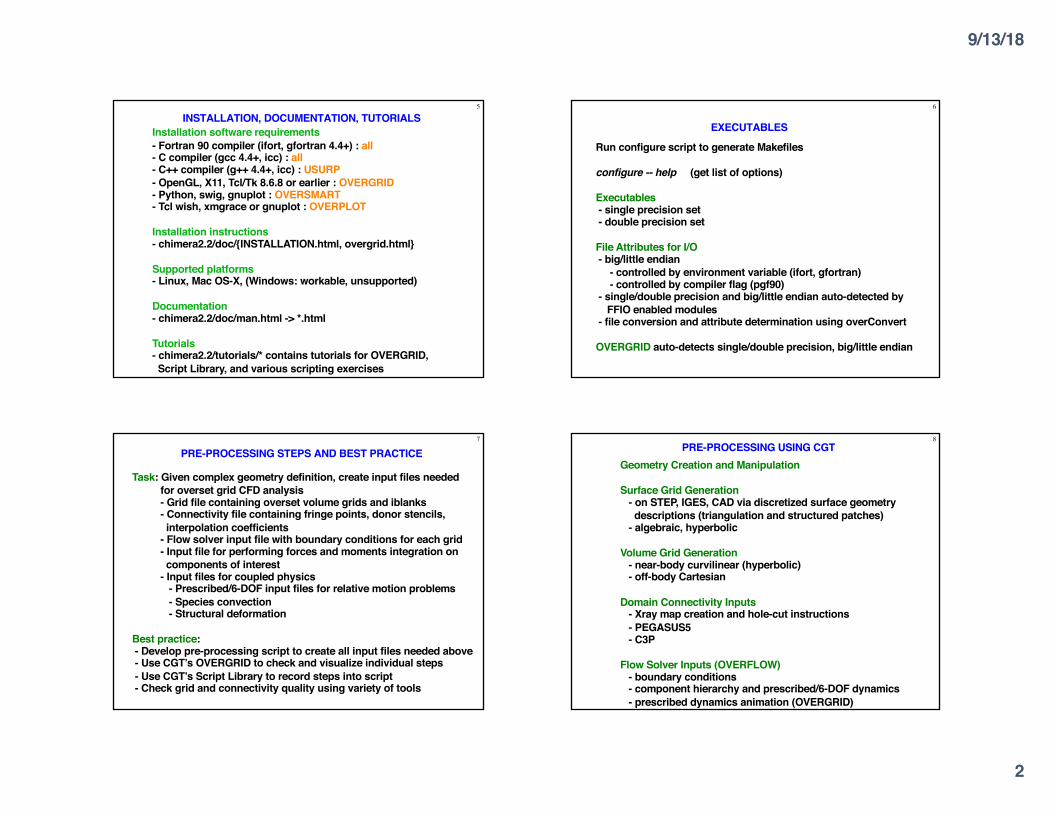
CHIMERA GRID TOOLS (CGT) Version 2.2
Authors2.2: William Chan, Shishir Pandya, Stuart Rogers, James Jensen, Henry LeeEarlier: David Kao, Pieter Buning, Robert Meakin, David Boger, Steve Nash
AvailabilityNASA Software Catalog (https://software.nasa.gov/software/ARC-16025-1B)- U.S. citizens/permanent residents working under U.S. organization in the U.S.- Fill out and return Software Usage Agreement form- Source (Linux, Unix, Mac OS-X)- Version 2.2+ available for use by authors’ associated projects
70+ tools
~250 procs
What is CGT- A collection of software toolsfor pre- and post-processingof overset grid CFD computations
9/13/18
2
5
INSTALLATION, DOCUMENTATION, TUTORIALSInstallation software requirements- Fortran 90 compiler (ifort, gfortran 4.4+) : all- C compiler (gcc 4.4+, icc) : all- C++ compiler (g++ 4.4+, icc) : USURP- OpenGL, X11, Tcl/Tk 8.6.8 or earlier : OVERGRID- Python, swig, gnuplot : OVERSMART- Tcl wish, xmgrace or gnuplot : OVERPLOT
Installation instructions- chimera2.2/doc/{INSTALLATION.html, overgrid.html}
Supported platforms- Linux, Mac OS-X, (Windows: workable, unsupported)
Documentation- chimera2.2/doc/man.html -> *.html
Tutorials- chimera2.2/tutorials/* contains tutorials for OVERGRID,Script Library, and various scripting exercises
6
EXECUTABLES
Run configure script to generate Makefiles
configure -- help (get list of options)
Executables- single precision set- double precision set
File Attributes for I/O- big/little endian
- controlled by environment variable (ifort, gfortran) - controlled by compiler flag (pgf90)
- single/double precision and big/little endian auto-detected byFFIO enabled modules
- file conversion and attribute determination using overConvert
OVERGRID auto-detects single/double precision, big/little endian
7
PRE-PROCESSING STEPS AND BEST PRACTICE
Task: Given complex geometry definition, create input files neededfor overset grid CFD analysis- Grid file containing overset volume grids and iblanks- Connectivity file containing fringe points, donor stencils,interpolation coefficients
- Flow solver input file with boundary conditions for each grid- Input file for performing forces and moments integration oncomponents of interest
- Input files for coupled physics- Prescribed/6-DOF input files for relative motion problems- Species convection- Structural deformation
Best practice: - Develop pre-processing script to create all input files needed above- Use CGT’s OVERGRID to check and visualize individual steps- Use CGT’s Script Library to record steps into script- Check grid and connectivity quality using variety of tools
8PRE-PROCESSING USING CGT
Geometry Creation and Manipulation
Surface Grid Generation- on STEP, IGES, CAD via discretized surface geometrydescriptions (triangulation and structured patches)
- algebraic, hyperbolic
Volume Grid Generation- near-body curvilinear (hyperbolic)- off-body Cartesian
Domain Connectivity Inputs- Xray map creation and hole-cut instructions- PEGASUS5- C3P
Flow Solver Inputs (OVERFLOW)- boundary conditions- component hierarchy and prescribed/6-DOF dynamics- prescribed dynamics animation (OVERGRID)
9/13/18
3
9
GEOMETRY CREATIONScript Library has macros to create
- Points- Straight lines- Analytic curves- Cylinders- Spheres- Frustums- Cartesian boxes- Airfoil shapes- > NACA 4 and 5 digit series- > PARSEC
Combine with basic macros to generate more complex shapes
- Translate- Scale- Rotate- Mirror- Extract- Concatenate- Revolve- Duplicate
STEP, IGES via Engineering Sketch Pad (ESP)- Boundary Representation (BRep) solids- Use EGADS2SRF module to generate discrete representations- Open source
Native CAD (Pro-E, Catia V5, Parasolid, OpenCASCADE, SolidWorks, UniGraphics, FELISA) via CAPRI library from CADNexus
- Use CAD2SRF module to generate surface triangulations- Need CAD license and CAPRI users license- Not tested under CGT 2.2
Surface Triangulation- CART3D (.tri, .triq, .trix)- UCD (.ucd)- STL (.stl)- FRO (.fro)- FAST (.fst)
Structured Surface Patches- PLOT3D format
10
GEOMETRY INPUT
11
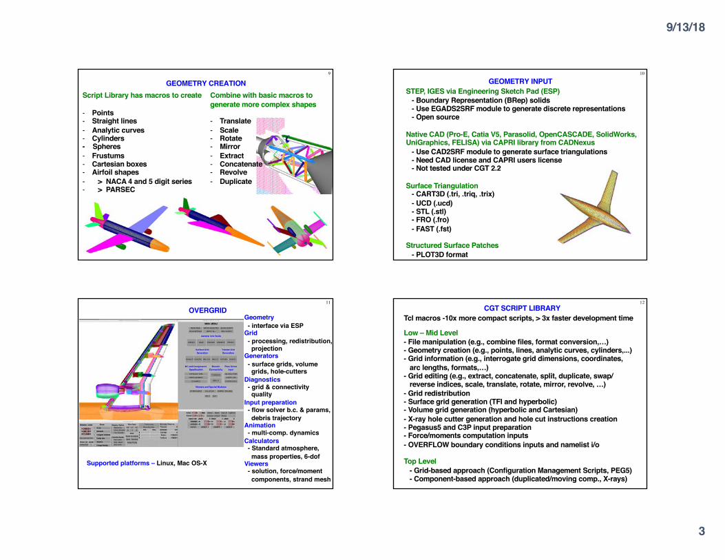
OVERGRID
Supported platforms – Linux, Mac OS-X
Geometry- interface via ESP
Grid- processing, redistribution,projection
Generators- surface grids, volumegrids, hole-cutters
Diagnostics- grid & connectivityquality
Input preparation- flow solver b.c. & params,debris trajectory
Animation- multi-comp. dynamics
Calculators- Standard atmosphere,mass properties, 6-dof
Viewers- solution, force/moment components, strand mesh
12CGT SCRIPT LIBRARY
Tcl macros -10x more compact scripts, > 3x faster development time
Low – Mid Level- File manipulation (e.g., combine files, format conversion,…)- Geometry creation (e.g., points, lines, analytic curves, cylinders,...)- Grid information (e.g., interrogate grid dimensions, coordinates,
arc lengths, formats,…)- Grid editing (e.g., extract, concatenate, split, duplicate, swap/
reverse indices, scale, translate, rotate, mirror, revolve, …)- Grid redistribution- Surface grid generation (TFI and hyperbolic)- Volume grid generation (hyperbolic and Cartesian)- X-ray hole cutter generation and hole cut instructions creation- Pegasus5 and C3P input preparation- Force/moments computation inputs- OVERFLOW boundary conditions inputs and namelist i/o
Top Level- Grid-based approach (Configuration Management Scripts, PEG5)- Component-based approach (duplicated/moving comp., X-rays)
9/13/18
4
13
PRE-PROCESSING STRATEGY USING SCRIPTS
Scripting approach- rapid replay of all steps- easy to parameterize inputs (e.g., grid stretching, spacings, etc.)- easy to make small changes- recommended even for one-of-a-kind cases- modification needed if surface topology changes
Surface Grid Generation- generate grids from
- surface triangulation- surface feature curves
Volume Grid Generation- near-body hyperbolic grids, off-body Cartesian grids
Domain Connectivity, Force/Moments Computation, Flow Solver Inputs- construct and store common database in script (boundary conditions, component definitions, etc.)
Derived from STEP / IGES / CAD, or supplied
14
DISTRIBUTED TEAM-BASED SCRIPT DEVELOPMENT- Identify components of a complex configuration
- A component is a geometric part and may be modeled by one or more grids
- Create stand-alone script for each component- generation of surface and volume grids- domain connectivity inputs (X-ray maps)- solver boundary conditions- forces and moments integration inputs
- Each component script can be created by different developers
- Use file repository system to update script so that each team member can getmost up-to-date version of each script
- Share global parameters file (e.g., wall spacing, global spacing, str. ratio, etc.)
- Each developer is responsible for grid connectivity of individual component
- Create master script to call component scripts, assemble final grid system,generate input files for domain connectivity, force/ moment integration, flowsolver
15
POST-PROCESSING USING CGT
Forces and Moments Computation (mixsur/overint, usurp)
Solution Convergence Analysis- solution/turb. model residuals, forces/moments- one page overview (oversmart)- individual plots (overplot)
Flow Visualization (overgrid)- scalar and vector functions- turb. model dependent variables, species partial densities- unsteady 2-D solution animation
Component Line Loads (triload)- sectional and cumulative line loads- Cp on plane cuts
Dynamics Animation (overgrid)- 6-DOF dynamics output from flow solver
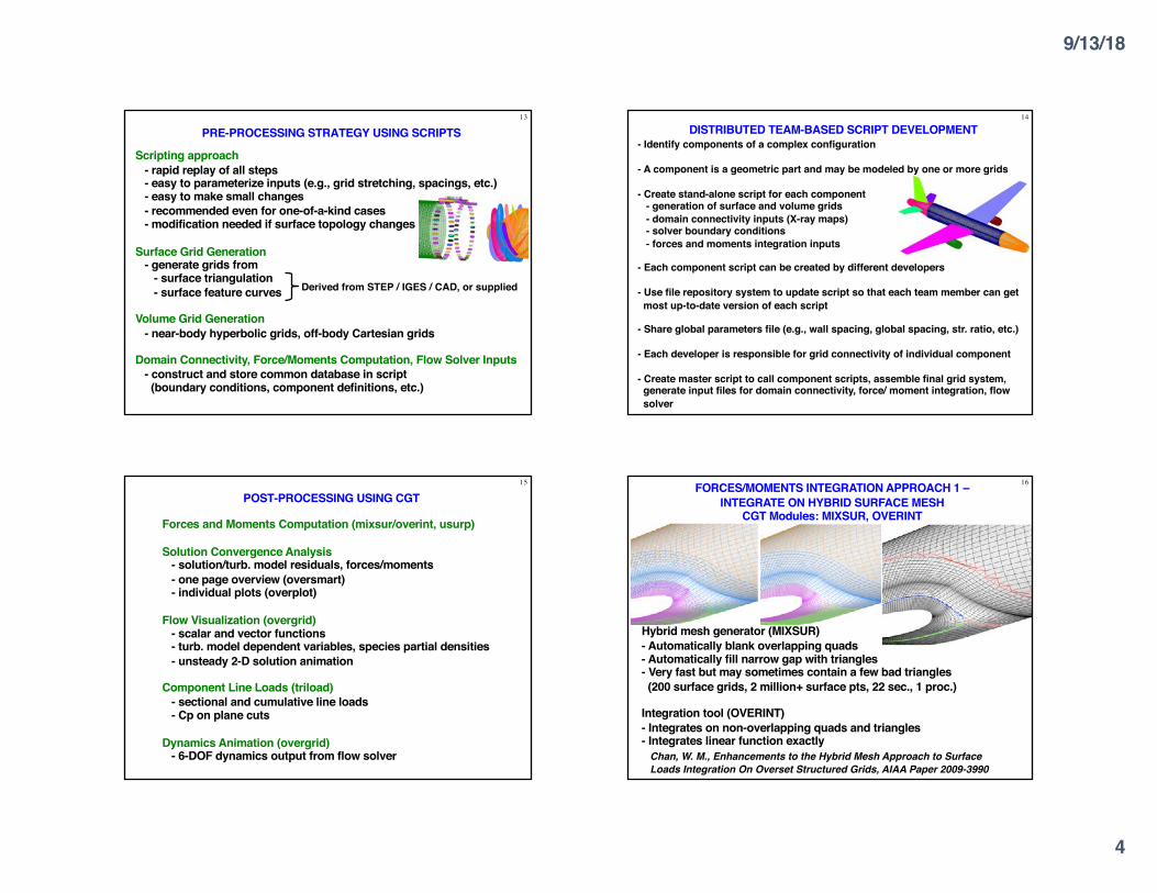
16FORCES/MOMENTS INTEGRATION APPROACH 1 –INTEGRATE ON HYBRID SURFACE MESH
CGT Modules: MIXSUR, OVERINT
Hybrid mesh generator (MIXSUR)- Automatically blank overlapping quads- Automatically fill narrow gap with triangles- Very fast but may sometimes contain a few bad triangles(200 surface grids, 2 million+ surface pts, 22 sec., 1 proc.)
Integration tool (OVERINT)- Integrates on non-overlapping quads and triangles- Integrates linear function exactly
Chan, W. M., Enhancements to the Hybrid Mesh Approach to Surface Loads Integration On Overset Structured Grids, AIAA Paper 2009-3990
9/13/18
5
17
OVERINT OUTPUT FILES
- Surface triangulation solution file derived from hybrid surface meshgenerated by MIXSUR (.triq)
- Surface distributions of local forces and moments
- Four unstructured surface triangulation files, each withcell-centered scalar variables (extended CART3D .i.tri format)
(1) Cell DF (2) Cell DF / Cell area(3) Cell DM(4) Cell DM / Cell area
- Scalars: X, Y, Z components of forces/momentstotal magnitude, pressure, viscous, momentum contributionslocal cell area
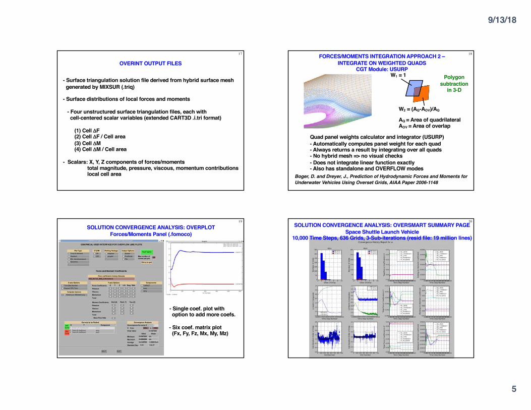
18FORCES/MOMENTS INTEGRATION APPROACH 2 –INTEGRATE ON WEIGHTED QUADS
CGT Module: USURP
Quad panel weights calculator and integrator (USURP)- Automatically computes panel weight for each quad- Always returns a result by integrating over all quads- No hybrid mesh => no visual checks - Does not integrate linear function exactly- Also has standalone and OVERFLOW modes
W1 = 1
W2 = (AQ-AOV)/AQ
AQ = Area of quadrilateralAOV = Area of overlap
Boger, D. and Dreyer, J., Prediction of Hydrodynamic Forces and Moments for Underwater Vehicles Using Overset Grids, AIAA Paper 2006-1148
Polygon subtraction
in 3-D
19
SOLUTION CONVERGENCE ANALYSIS: OVERPLOTForces/Moments Panel (.fomoco)
- Single coef. plot withoption to add more coefs.
- Six coef. matrix plot(Fx, Fy, Fz, Mx, My, Mz)
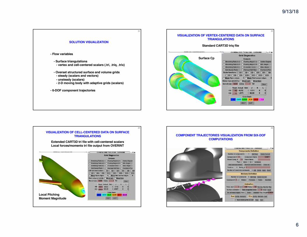
20SOLUTION CONVERGENCE ANALYSIS: OVERSMART SUMMARY PAGE
Space Shuttle Launch Vehicle10,000 Time Steps, 636 Grids, 3-Sub-iterations (resid file: 19 million lines)
9/13/18
6
21
SOLUTION VISUALIZATION
- Flow variables
- Surface triangulations- vertex and cell-centered scalars (.tri, .triq, .trix)
- Overset structured surface and volume grids- steady (scalars and vectors)- unsteady (scalars)- 2-D moving body with adaptive grids (scalars)
- 6-DOF component trajectories
22
VISUALIZATION OF VERTEX-CENTERED DATA ON SURFACE TRIANGULATIONS
Surface Cp
Standard CART3D triq file
23
VISUALIZATION OF CELL-CENTERED DATA ON SURFACE TRIANGULATIONS
Local Pitching Moment Magnitude
Extended CART3D tri file with cell-centered scalarsLocal forces/moments tri file output from OVERINT
24
COMPONENT TRAJECTORIES VISUALIZATION FROM SIX-DOF COMPUTATIONS
9/13/18
7
25MAIN NEW FEATURES IN CGT 2.2
- Geometry interface for STEP and IGES files via Engineering Sketch Pad (ESP)(EGADS2SRF, SRF2EGADS, OVERGRID)
- Diagnostics for grid quality, domain connectivity (GRIDINF, INTCHK, OVERGRID)
- Visualization of- cut planes for curvilinear grids/solutions (OVERGRID)- components defined for forces/moments computation (OVERGRID)
- Command-Iine options for image dump (OVERGRID)
- Auto-determination/conversion of file types/attributes (FFIO Lib., overConvert)
- Multi-threaded Tcl script execution for volume mesh generation (Script Library)
- Residual history plots for components (OVERPLOT)
- Line loads computation (TRILOAD)
- Tutorial for script development for complete overset CFD pre-processing tasks
- See chimera2.2/doc/cgt2.2.txt for more details
26
GEOMETRY INTERFACE- Engineering Sketch Pad (ESP) open source library from MIT
- Parametric geometry creation and processing
- Geometry formats allowed- Boundary Representation (BRep) solids in STEP or IGES files- Engineering Geometry Aircraft Design System (EGADS) geometryfiles
- CGT modules- EGADS2SRF generates discrete representations from geometry- SRF2EGADS projects discrete meshes onto geometry- OVERGRID provides GUI front end
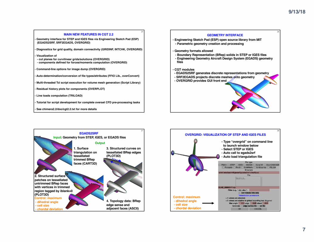
27EGADS2SRF
1. Surface triangulation on tessellated trimmed BRepfaces (CART3D)
2. Structured surface patches on tessellated untrimmed BRep faces with vertices in trimmed region tagged by iblank=0 (PLOT3D)
3. Structured curves on tessellated BRep edges (PLOT3D)
4. Topology data: BRepedge sense and adjacent faces (ASCII)
OutputInput: Geometry from STEP, IGES, or EGADS files
Control: maximum - dihedral angle- cell size- chordal deviation
28
OVERGRID: VISUALIZATION OF STEP AND IGES FILES
- Type “overgrid” on command lineto launch window below
- Select STEP or IGES- Auto call to egads2srf- Auto load triangulation file
Control: maximum - dihedral angle- cell size- chordal deviation
9/13/18
8
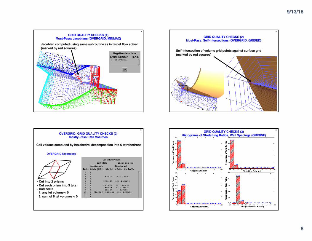
29
GRID QUALITY CHECKS (1)Must-Pass: Jacobians (OVERGRID, MINMAX)
Jacobian computed using same subroutine as in target flow solver(marked by red squares)
30
GRID QUALITY CHECKS (2)Must-Pass: Self-Intersections (OVERGRID, GRIDED)
Self-intersection of volume grid points against surface grid(marked by red squares)
31
OVERGRID: GRID QUALITY CHECKS (2)Mostly-Pass: Cell Volumes
Cell volume computed by hexahedral decomposition into 6 tetrahedrons
- Cut into 2 prisms- Cut each prism into 3 tets- Bad cell if1. any tet volume < 02. sum of 6 tet volumes < 0
OVERGRID Diagnostic
32GRID QUALITY CHECKS (3) Histograms of Stretching Ratios, Wall Spacings (GRIDINF)
9/13/18
9
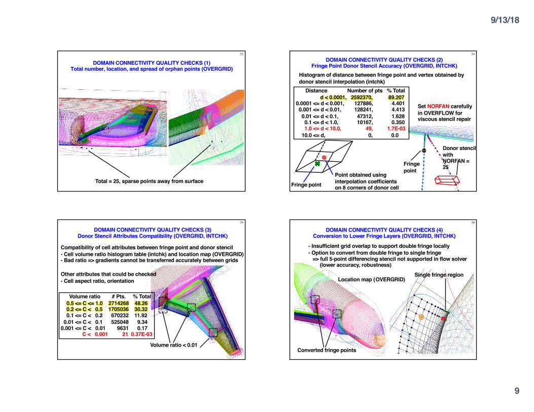
33
DOMAIN CONNECTIVITY QUALITY CHECKS (1)Total number, location, and spread of orphan points (OVERGRID)
Total = 25, sparse points away from surface
34
DOMAIN CONNECTIVITY QUALITY CHECKS (2)Fringe Point Donor Stencil Accuracy (OVERGRID, INTCHK)
Histogram of distance between fringe point and vertex obtained by donor stencil interpolation (intchk)
Fringe pointPoint obtained using interpolation coefficients on 8 corners of donor cell
Distance Number of pts % Totald < 0.0001, 2592370, 89.207
0.0001 <= d < 0.001, 127886, 4.4010.001 <= d < 0.01, 128241, 4.4130.01 <= d < 0.1, 47312, 1.6280.1 <= d < 1.0, 10167, 0.3501.0 <= d < 10.0, 49, 1.7E-03
10.0 <= d, 0, 0.0
Fringe point
Set NORFAN carefully in OVERFLOW for viscous stencil repair
Donor stencil with NORFAN = 25
35
DOMAIN CONNECTIVITY QUALITY CHECKS (3)Donor Stencil Attributes Compatibility (OVERGRID, INTCHK)
Compatibility of cell attributes between fringe point and donor stencil - Cell volume ratio histogram table (intchk) and location map (OVERGRID)- Bad ratio => gradients cannot be transferred accurately between grids
Volume ratio < 0.01
Volume ratio # Pts. % Total0.5 <= C <= 1.0 2714268 48.260.2 <= C < 0.5 1705036 30.320.1 <= C < 0.2 670232 11.92
0.01 <= C < 0.1 525048 9.340.001 <= C < 0.01 9631 0.17
C < 0.001 21 0.37E-03
Other attributes that could be checked- Cell aspect ratio, orientation
36
DOMAIN CONNECTIVITY QUALITY CHECKS (4)Conversion to Lower Fringe Layers (OVERGRID, INTCHK)
Converted fringe points
- Insufficient grid overlap to support double fringe locally- Option to convert from double fringe to single fringe
=> full 5-point differencing stencil not supported in flow solver(lower accuracy, robustness)
Single fringe regionLocation map (OVERGRID)
9/13/18
10
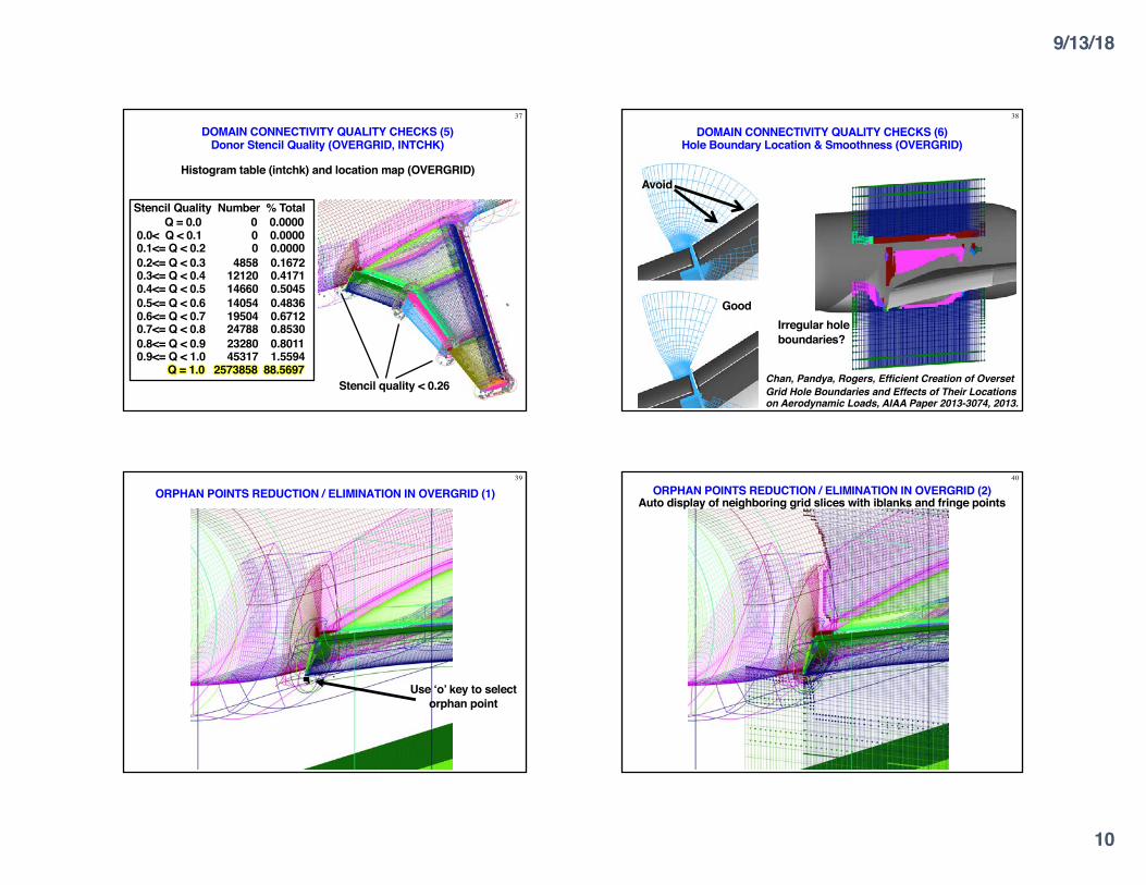
37
DOMAIN CONNECTIVITY QUALITY CHECKS (5)Donor Stencil Quality (OVERGRID, INTCHK)
Histogram table (intchk) and location map (OVERGRID)
Stencil Quality Number % TotalQ = 0.0 0 0.0000
0.0< Q < 0.1 0 0.00000.1<= Q < 0.2 0 0.00000.2<= Q < 0.3 4858 0.16720.3<= Q < 0.4 12120 0.41710.4<= Q < 0.5 14660 0.50450.5<= Q < 0.6 14054 0.48360.6<= Q < 0.7 19504 0.67120.7<= Q < 0.8 24788 0.85300.8<= Q < 0.9 23280 0.80110.9<= Q < 1.0 45317 1.5594
Q = 1.0 2573858 88.5697Stencil quality < 0.26
38
DOMAIN CONNECTIVITY QUALITY CHECKS (6)Hole Boundary Location & Smoothness (OVERGRID)
Avoid
GoodIrregular hole boundaries?
Chan, Pandya, Rogers, Efficient Creation of Overset Grid Hole Boundaries and Effects of Their Locations on Aerodynamic Loads, AIAA Paper 2013-3074, 2013.
39
ORPHAN POINTS REDUCTION / ELIMINATION IN OVERGRID (1)
Use ‘o’ key to select orphan point
40
ORPHAN POINTS REDUCTION / ELIMINATION IN OVERGRID (2)Auto display of neighboring grid slices with iblanks and fringe points
9/13/18
11
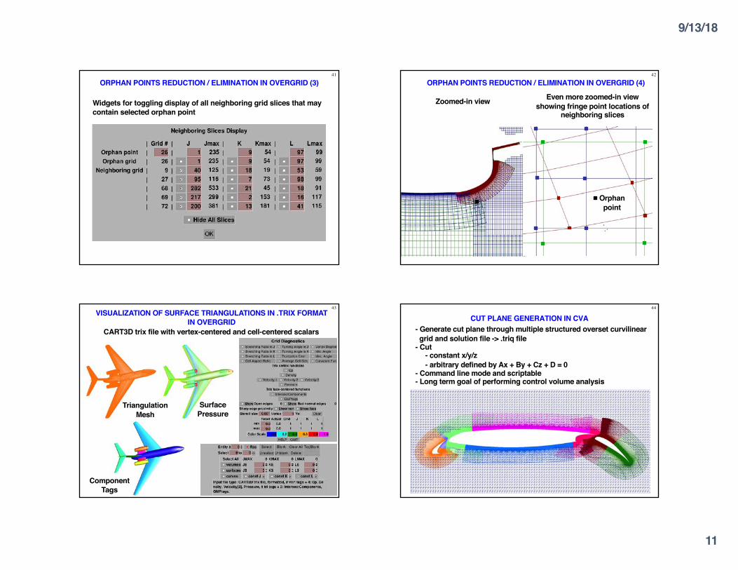
41
ORPHAN POINTS REDUCTION / ELIMINATION IN OVERGRID (3)
Widgets for toggling display of all neighboring grid slices that may contain selected orphan point
42
ORPHAN POINTS REDUCTION / ELIMINATION IN OVERGRID (4)
Zoomed-in view Even more zoomed-in view showing fringe point locations of
neighboring slices
Orphan point
43VISUALIZATION OF SURFACE TRIANGULATIONS IN .TRIX FORMAT
IN OVERGRIDCART3D trix file with vertex-centered and cell-centered scalars
Triangulation Mesh
Surface Pressure
Component Tags
44
CUT PLANE GENERATION IN CVA- Generate cut plane through multiple structured overset curvilineargrid and solution file -> .triq file
- Cut- constant x/y/z- arbitrary defined by Ax + By + Cz + D = 0
- Command line mode and scriptable- Long term goal of performing control volume analysis
9/13/18
12
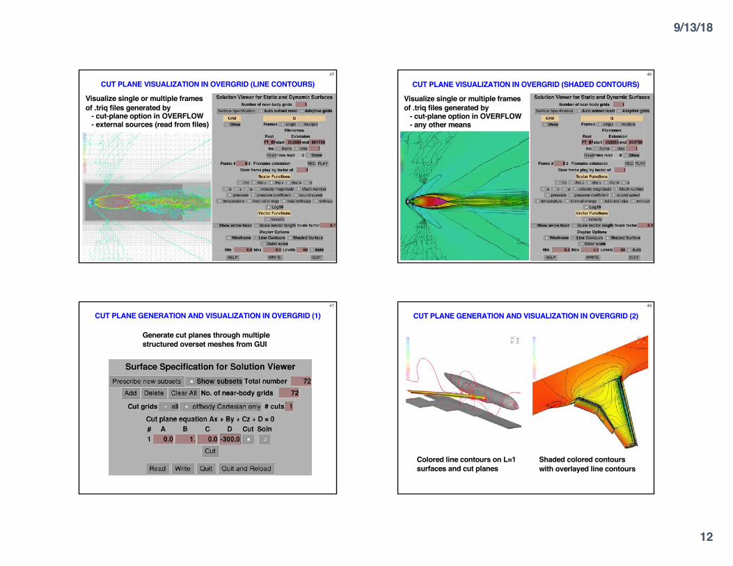
45
CUT PLANE VISUALIZATION IN OVERGRID (LINE CONTOURS)
Visualize single or multiple frames of .triq files generated by
- cut-plane option in OVERFLOW- external sources (read from files)
46
CUT PLANE VISUALIZATION IN OVERGRID (SHADED CONTOURS)
Visualize single or multiple frames of .triq files generated by
- cut-plane option in OVERFLOW- any other means
47
CUT PLANE GENERATION AND VISUALIZATION IN OVERGRID (1)
Generate cut planes through multiple structured overset meshes from GUI
48
CUT PLANE GENERATION AND VISUALIZATION IN OVERGRID (2)
Colored line contours on L=1 surfaces and cut planes
Shaded colored contours with overlayed line contours

9/13/18
13
49
Toggle display of each component in different colors
OVERGRID: VISUALIZATION OF COMPONENTS DEFINED FOR FORCES/MOMENTS COMPUTATION
- Recent complex configuration applications: 100+ components, eachcomponent may contain from a few to 100+ surface subsets
- Need visual check of grid indices used to define components forforces/moments computation
50
Toggle display of each component in different colors
OVERGRID: VISUALIZATION OF COMPONENTS DEFINED FOR FORCES/MOMENTS COMPUTATION
- Recent complex configuration applications: 100+ components, eachcomponent may contain from a few to 100+ surface subsets
- Need visual check of grid indices used to define components forforces/moments computation
51OVERGRID: VISUALIZATION OF COMPONENTS DEFINED
FOR FORCES/MOMENTS COMPUTATION (BIG CASE)
Click to second panel to see components 76-147
52
OVERGRID: COMMAND LINE OPTIONS
Scripted dumping of image files in non-interactive mode enabled by command line options-2 : dual screen-l/-r : location of smaller screen for horizontal stack (l=left, r=right)+x/+y : x and y shifts for window placement-cmd : read command line arguments from specified file-cntrfun/-shadfun/-wirefun : 0/1 turn off or on contour/shaded/wireframe
display for solution function-dp : use double precision mode to read ascii structured grid files-fun : plot function fun_name in solution viewer, valid fun_name include
q1,q2,...,u,v,w,velocity magnitude,Mach number,pressure,Cp,sound speed,temperature,internal energy,total enthalpy,entropy
-img : dump image to specified filename (non-interactive mode)-maxval/-minval : set max/min value of contours to specified value-nlevel : set number of contour levels-noax/-nogrid : do not display axis/grid wireframe -nolog : do not write overgrid.log file-qfile : load structured grid solution from specified solution file-sub : load solution subsets from specified subsets file-vp : load view point from specified viewpoint file
9/13/18
14
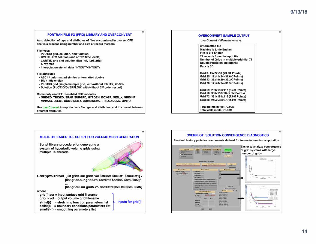
53FORTRAN FILE I/O (FFIO) LIBRARY AND OVERCONVERT
Auto detection of type and attributes of files encountered in overset CFD analysis process using number and size of record markers
File types- PLOT3D grid, solution, and function- OVERFLOW solution (one or two time levels)- CART3D grid and solution files (.tri, .i.tri, .triq)- X-ray map- Interpolation stencil data (INTOUT/XINTOUT)
File attributes- ASCII / unformatted single / unformatted double- Big / little endian- PLOT3D grid (single/multiple grid, with/without iblanks, 2D/3D)- Solution (PLOT3D/OVERFLOW, with/without 2nd order restart)
Commonly used FFIO enabled CGT modules- GRIDED, TRIGED, SRAP, SURGRD, HYPGEN, BOXGR, GEN_X, GRIDINFMINMAX, LSECT, COMBINEMX, COMBINEMQ, TRILOADCMV, QINFO
Use overConvert to report/check file type and attributes, and to convert between different attributes
54
OVERCONVERT SAMPLE OUTPUToverConvert -i filename -v -h -s
unformatted fileMachine is Little EndianFile is Big Endian74 records found in input fileNumber of Grids in multiple grid file: 72Double Precision, no IBlanksData is 3D
Grid 3: 15x27x59 (23.9K Points)Grid 25: 17x41x54 (37.6K Points)Grid 13: 35x19x59 (39.2K Points)Grid 20: 17x43x54 (39.5K Points)…Grid 69: 289x159x117 (5.4M Points)Grid 58: 386x153x98 (5.8M Points)Grid 72: 381x181x115 (7.9M Points)Grid 30: 215x538x97 (11.2M Points)
Total points in file: 72.92MTotal cells in file: 70.93M
55
MULTI-THREADED TCL SCRIPT FOR VOLUME MESH GENERATION
GenHypVolThread [list grid1.sur grid1.vol $strlist1 $bclist1 $smulist1] \[list grid2.sur grid2.vol $strlist2 $bclist2 $smulist2] \…[list gridN.sur gridN.vol $strlistN $bclistN $smulistN]
wheregrid{i}.sur = input surface grid filenamegrid{i}.vol = output volume grid filenamestrlist{i} = stretching function parameters listbclist{i} = boundary conditions parameters listsmulist{i} = smoothing parameters list
Inputs for grid{i}
Script library procedure for generating a system of hyperbolic volume grids using multiple Tcl threads
56
OVERPLOT: SOLUTION CONVERGENCE DIAGNOSTICSResidual history plots for components defined for forces/moments computation
Easier to analyze convergence of grid systems with large number of grids
9/13/18
15
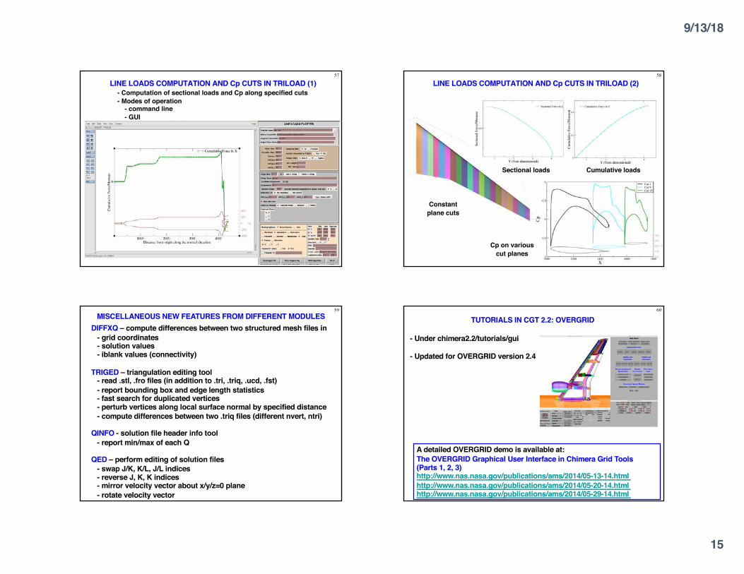
57
LINE LOADS COMPUTATION AND Cp CUTS IN TRILOAD (1)- Computation of sectional loads and Cp along specified cuts- Modes of operation
- command line- GUI
58
LINE LOADS COMPUTATION AND Cp CUTS IN TRILOAD (2)
Constant plane cuts
Sectional loads Cumulative loads
Cp on various cut planes
DIFFXQ – compute differences between two structured mesh files in- grid coordinates- solution values- iblank values (connectivity)
TRIGED – triangulation editing tool- read .stl, .fro files (in addition to .tri, .triq, .ucd, .fst)- report bounding box and edge length statistics- fast search for duplicated vertices- perturb vertices along local surface normal by specified distance- compute differences between two .triq files (different nvert, ntri)
QINFO - solution file header info tool- report min/max of each Q
QED – perform editing of solution files- swap J/K, K/L, J/L indices- reverse J, K, K indices- mirror velocity vector about x/y/z=0 plane- rotate velocity vector
59MISCELLANEOUS NEW FEATURES FROM DIFFERENT MODULES
- Under chimera2.2/tutorials/gui
- Updated for OVERGRID version 2.4
60
TUTORIALS IN CGT 2.2: OVERGRID
A detailed OVERGRID demo is available at:The OVERGRID Graphical User Interface in Chimera Grid Tools (Parts 1, 2, 3)http://www.nas.nasa.gov/publications/ams/2014/05-13-14.htmlhttp://www.nas.nasa.gov/publications/ams/2014/05-20-14.htmlhttp://www.nas.nasa.gov/publications/ams/2014/05-29-14.html
9/13/18
16
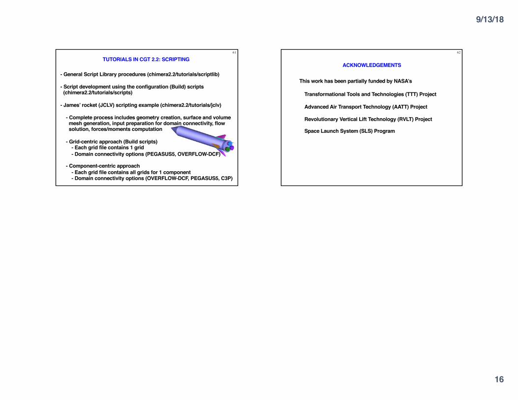
- General Script Library procedures (chimera2.2/tutorials/scriptlib)
- Script development using the configuration (Build) scripts(chimera2.2/tutorials/scripts)
- James’ rocket (JCLV) scripting example (chimera2.2/tutorials/jclv)
- Complete process includes geometry creation, surface and volumemesh generation, input preparation for domain connectivity, flowsolution, forces/moments computation
- Grid-centric approach (Build scripts)- Each grid file contains 1 grid- Domain connectivity options (PEGASUS5, OVERFLOW-DCF)
- Component-centric approach- Each grid file contains all grids for 1 component- Domain connectivity options (OVERFLOW-DCF, PEGASUS5, C3P)
61
TUTORIALS IN CGT 2.2: SCRIPTING62
ACKNOWLEDGEMENTS
This work has been partially funded by NASA’s
Transformational Tools and Technologies (TTT) Project
Advanced Air Transport Technology (AATT) Project
Revolutionary Vertical Lift Technology (RVLT) Project
Space Launch System (SLS) Program