Embed Size (px)
Citation preview
Origin of beam non-uniformity in a large Cs-seeded negative ion source
T. Inoue for M. HanadaJAERI Naka
Fourth IAEA Technical Meeting on"Negative Ion Based Neutral Beam Injectors”
Padova, ItaliaMay 9-11, 2005
2/19T. Inoue
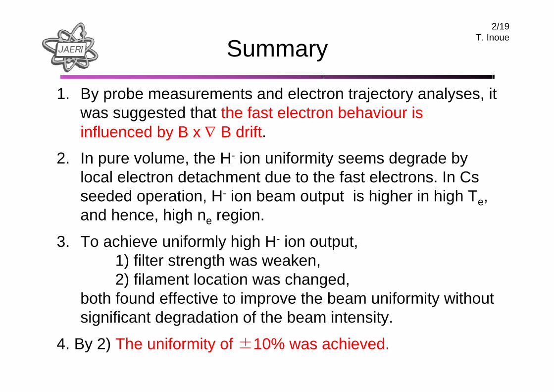
Summary
1. By probe measurements and electron trajectory analyses, it was suggested that the fast electron behaviour is influenced by B x ∇ B drift.
2. In pure volume, the H- ion uniformity seems degrade by local electron detachment due to the fast electrons. In Cs seeded operation, H- ion beam output is higher in high Te, and hence, high ne region.
3. To achieve uniformly high H- ion output, 1) filter strength was weaken, 2) filament location was changed,
both found effective to improve the beam uniformity without significant degradation of the beam intensity.
4. By 2) The uniformity of ±10% was achieved.
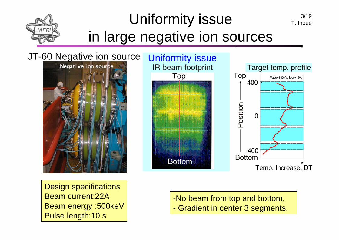
3/19T. InoueUniformity issue
in large negative ion sourcesJT-60 Negative ion source
Design specificationsBeam current:22A Beam energy :500keVPulse length:10 s
-No beam from top and bottom,- Gradient in center 3 segments.
Uniformity issue
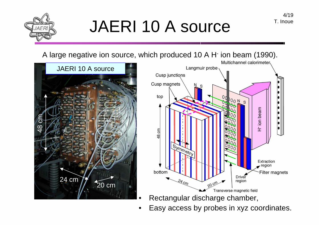
4/19T. InoueJAERI 10 A source
• Rectangular discharge chamber, • Easy access by probes in xyz coordinates.
JAERI 10 A source
24 cm20 cm
48 c
m
A large negative ion source, which produced 10 A H- ion beam (1990).
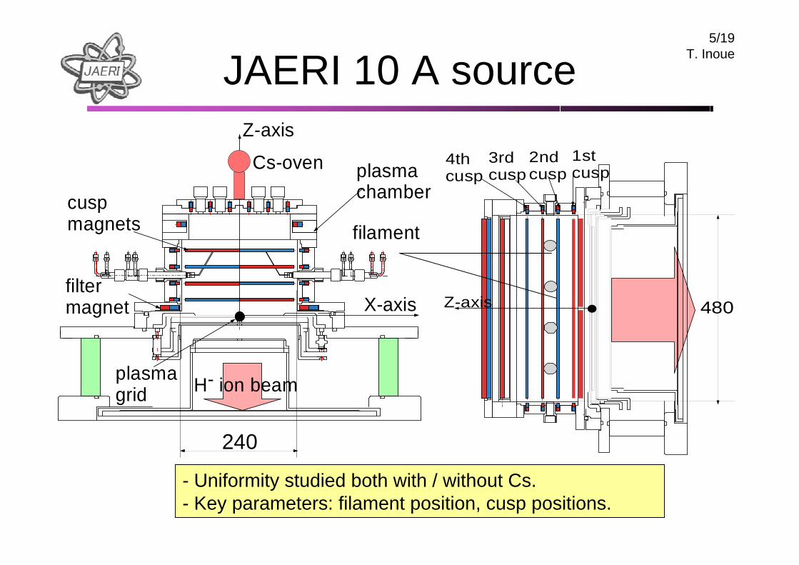
5/19T. InoueJAERI 10 A source
H- ion beam
plasmachamber
filamentcuspmagnets
filtermagnet
plasmagrid
Z-axis
X-axis
240
Cs-oven 1stcusp
2ndcusp
3rdcusp
4thcusp
Z-axis 480
- Uniformity studied both with / without Cs. - Key parameters: filament position, cusp positions.
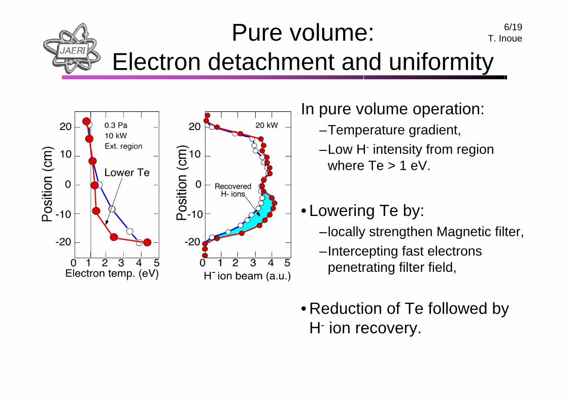
6/19T. InouePure volume:
Electron detachment and uniformity
In pure volume operation:–Temperature gradient,–Low H- intensity from region
where Te > 1 eV.
• Lowering Te by:–locally strengthen Magnetic filter,–Intercepting fast electrons
penetrating filter field,
• Reduction of Te followed by H- ion recovery.
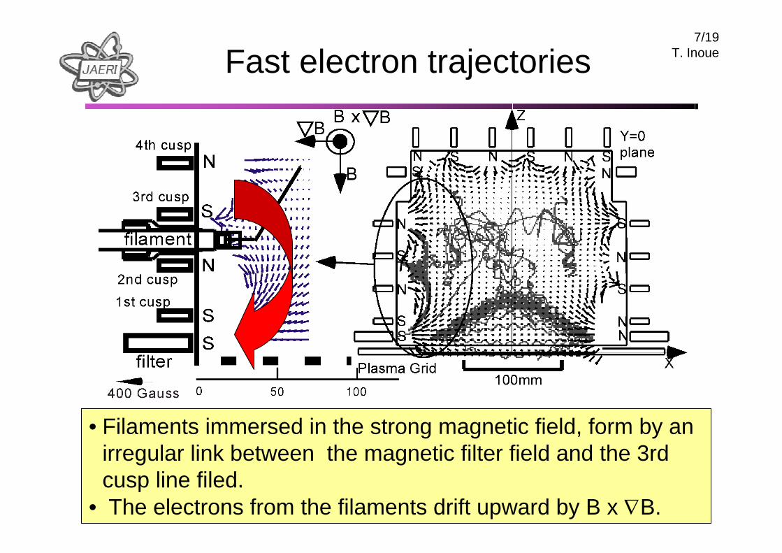
7/19T. InoueFast electron trajectories
• Filaments immersed in the strong magnetic field, form by an irregular link between the magnetic filter field and the 3rd cusp line filed.
• The electrons from the filaments drift upward by B x ∇B.
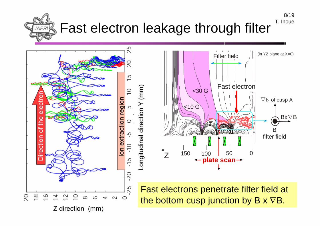
8/19T. Inoue
Fast electron leakage through filter(in YZ plane at X=0)
Bfilter field
Bx∇B
▽B of cusp A<10 G
050100150Z
<30 GFast electron
plate scan
Filter field
A A
Fast electrons penetrate filter field at the bottom cusp junction by B x ∇B.
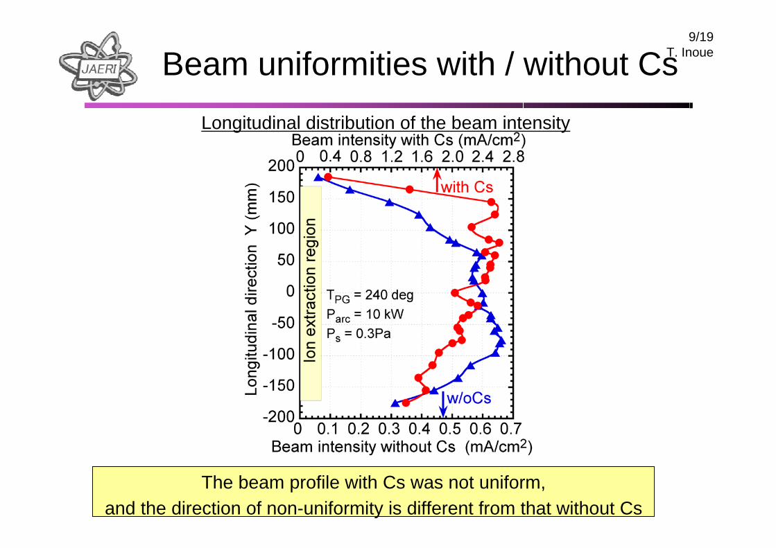
9/19T. InoueBeam uniformities with / without Cs
The beam profile with Cs was not uniform, and the direction of non-uniformity is different from that without Cs
Longitudinal distribution of the beam intensity
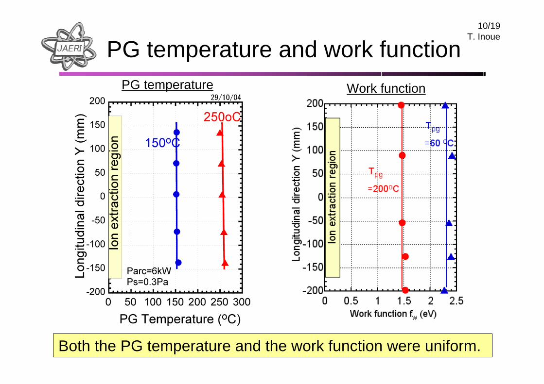
10/19T. Inoue
PG temperature and work functionWork function PG temperature
Both the PG temperature and the work function were uniform.
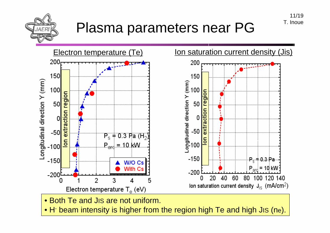
11/19T. InouePlasma parameters near PG
Ion saturation current density (Jis) Electron temperature (Te)
• Both Te and JIS are not uniform.• H- beam intensity is higher from the region high Te and high JIS (ne).
12/19T. Inoue
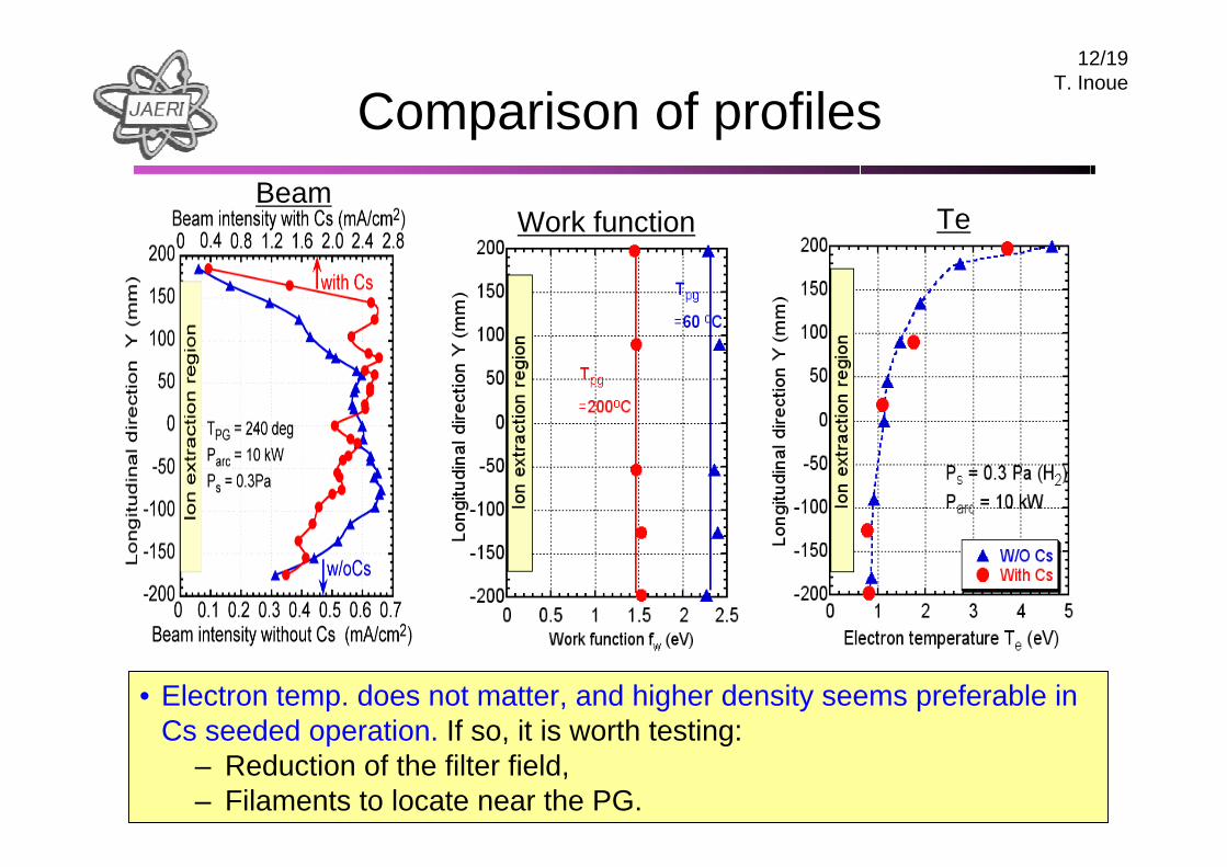
Comparison of profilesBeam
Work function Te
• Electron temp. does not matter, and higher density seems preferable in Cs seeded operation. If so, it is worth testing:
– Reduction of the filter field,– Filaments to locate near the PG.
13/19T. Inoue
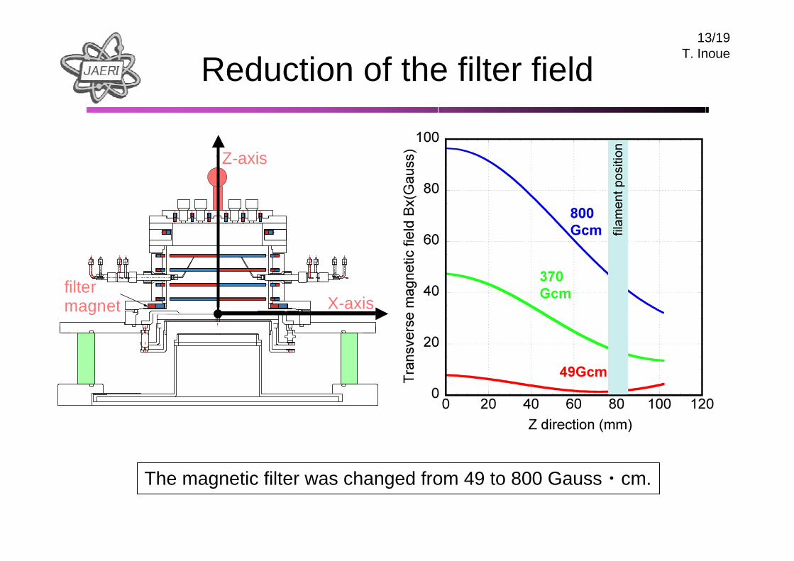
filtermagnet
Z-axis
X-axis
The magnetic filter was changed from 49 to 800 Gauss・cm.
Reduction of the filter field
14/19T. Inoue
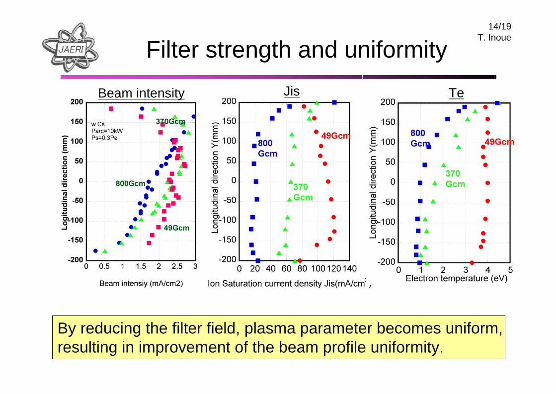
Filter strength and uniformity
Beam intensity Jis Te
By reducing the filter field, plasma parameter becomes uniform, resulting in improvement of the beam profile uniformity.
15/19T. Inoue
Filter strength and uniformity
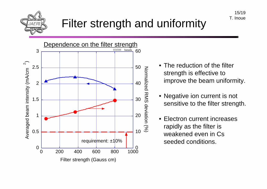
Dependence on the filter strength
0
0.5
1
1.5
2
2.5
3
0
10
20
30
40
50
60
0 200 400 600 800 1000
050506 hanada
Ave
rage
d be
am in
tens
ity (m
A/c
m2)
Norm
alized RM
S deviation (%
)
Filter strength (Gauss cm)
requirement: ±10%
• The reduction of the filter strength is effective to improve the beam uniformity.
• Negative ion current is not sensitive to the filter strength.
• Electron current increases rapidly as the filter is weakened even in Cs seeded conditions.
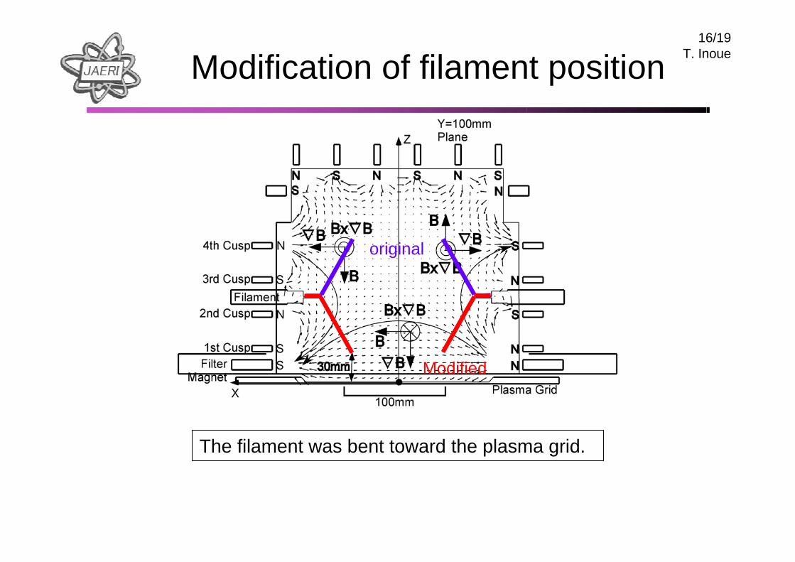
16/19T. InoueModification of filament position
original
Modified
The filament was bent toward the plasma grid.
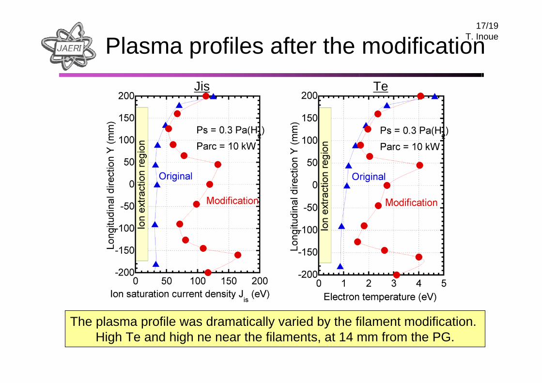
17/19T. InouePlasma profiles after the modification
Jis Te
The plasma profile was dramatically varied by the filament modification.High Te and high ne near the filaments, at 14 mm from the PG.
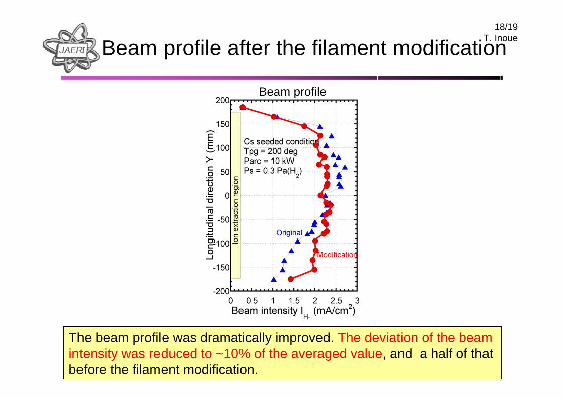
18/19T. InoueBeam profile after the filament modification
The beam profile was dramatically improved. The deviation of the beam intensity was reduced to ~10% of the averaged value, and a half of that before the filament modification.
Beam profile
19/19T. InoueDiscussion
• The H- ion profile in pure volume and Cesiated conditions are different. It should be noted that H- intensity is higher even from Te > 1 eV in cesiated case.
• This may suggest that in Cs seeded surface production,– H- ions produced on surface is extracted directly, independent of
reactions such as destruction by electron detachment in plasma,– Negative ion surface production seems strongly enhanced by plasma,
probably H0 and H+ densities.
• Less filter field and filaments located close to the PG is effective to achieve uniform H- ion profile, probably by less B x ∇B drift and uniform H0 and H+ production near PG .
• However, these modifications increase co-extracted electron current by a factor of ~10. New issue could arise for the electron suppression.


![Introduction and recent results of Multi-beam mask … · Introduction and recent results of ... inherited from existing EBM technologies ... 3.0 2.1 1.5 CD Uniformity [nm] Global](https://img.pdfslide.us/doc/110x75/5b5ca0727f8b9ad2198ccd24/introduction-and-recent-results-of-multi-beam-mask-introduction-and-recent-results.jpg)