Embed Size (px)
Citation preview
SPECIAL SECTION ON SMART HEALTH SENSING AND COMPUTATIONALINTELLIGENCE: FROM BIG DATA TO BIG IMPACTS
Received July 15, 2019, accepted September 3, 2019, date of publication September 6, 2019, date of current version September 20, 2019.
Digital Object Identifier 10.1109/ACCESS.2019.2939798
Organic Multi-Channel Optoelectronic Sensorsfor Wearable Health MonitoringYASSER KHAN 1, DONGGEON HAN1, JONATHAN TING1, MARUF AHMED1,RAMUNE NAGISETTY2, AND ANA C. ARIAS11Department of Electrical Engineering and Computer Sciences, University of California, Berkeley, CA 94720, USA2Intel Labs, Hillsboro, OR 97006, USA
Corresponding authors: Yasser Khan ([email protected]) and Ana C. Arias ([email protected])
This work was supported in part by the Intel Corporation via Semiconductor Research Corporation under Grant 2014-IN-2571, in part bythe Cambridge Display Technology Limited under Grant 02672530, and in part by the FlexTech under Grant AFOSR-42299.
ABSTRACT Recent progress in printed optoelectronics and their integration in wearable sensors havecreated new avenues for research in reflectance photoplethysmography (PPG) and oximetry. The reflection-mode sensor, which consists of light emitters and detectors, is a vital component of reflectance oximeters.Here, we report a systematic study of the reflectance oximeter sensor design in terms of component geometry,light emitter and detector spacing, and the use of an optical barrier between the emitter and the detector tomaximize sensor performance. Printed red and near-infrared (NIR) organic light-emitting diodes (OLEDs)and organic photodiodes (OPDs) are used to design three sensor geometries: (1) Rectangular geometry,where square OLEDs are placed at each side of the OPD; (2) Bracket geometry, where the OLEDs areshaped as brackets and placed around the square OPD; (3) Circular geometry, where the OLEDs are shapedas block arcs and placed around the circular OPD. Utilizing the bracket geometry, we observe 39.7% and18.2% improvement in PPG signal magnitude in the red and NIR channels compared to the rectangulargeometry, respectively. Using the circular geometry, we observe 48.6% and 9.2% improvements in the redand NIR channels compared to the rectangular geometry. Furthermore, a wearable two-channel PPG sensoris utilized to add redundancy to the measurement. Finally, inverse-variance weighting and template matchingalgorithms are implemented to improve the detection of heart rate from the multi-channel PPG signals.
INDEX TERMS Reflection photoplethysmography sensor, organic optoelectronics, pulse oximetry, wear-able sensors, printed electronics, flexible electronics.
I. INTRODUCTIONIn the human body, cardiac rhythm changes the blood vol-ume passing through the arteries, which generates a pul-satile signal that can be optically measured using a lightsource and a detector; this optical sensing technique is knownas photoplethysmography (PPG). Generally, the PPG sig-nal is used for calculating heart rate by utilizing only onelight source, and for measuring oxygen saturation (SpO2)by employing two light sources. Pulse oximeters measureSpO2 of blood by using PPG signals at two distinct wave-lengths where light absorption in oxygenated and deoxy-genated blood is different [1]. PPG and oximetry canbe performed in both transmission and reflection mode.Conventionally, transmission-mode pulse oximeter sensors
The associate editor coordinating the review of this manuscript andapproving it for publication was Qingxue Zhang.
composed of solid-state light-emitting diodes (LEDs) andphotodiodes (PDs) are used to measure SpO2 at the extrem-ities of the body where light can easily penetrate thinregions of tissue, such as the earlobes and the fingertips.However, this method of measuring SpO2 presents a fewlimitations - (i) Transmission-mode oximetry has limitedsensing locations [2], and (ii) Solid-state LEDs and PDs donot conform well to the skin, therefore, reduce the signal-to-noise ratio (SNR) [3].
Over the past few years, flexible and wearable sensors aregetting significant attention in both academic research andindustry due to their skin conformable form factors [4]–[16].Consequently, flexible optical sensors are extensively studiedfor PPG and oximetry as they enhance SNR and providedesign versatility [2], [3], [17]–[21]. Sensor fabrication andsensing methodology remain a strong focus of recent reports.However, the reflectance oximeter sensor design, which is
128114 This work is licensed under a Creative Commons Attribution 4.0 License. For more information, see http://creativecommons.org/licenses/by/4.0/ VOLUME 7, 2019
Y. Khan et al.: Organic Multi-Channel Optoelectronic Sensors for Wearable Health Monitoring
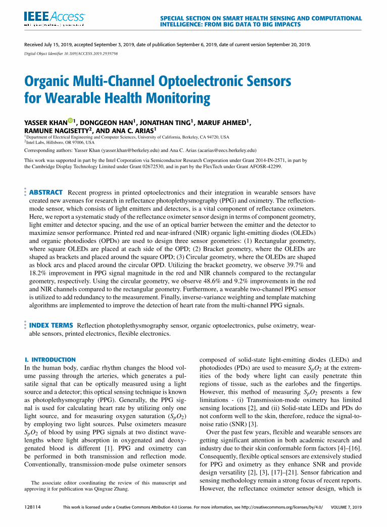
FIGURE 1. Multi-channel reflectance PPG sensor overview. (a) Schematic illustration of a wearable two-channel PPG sensor, where the PPG sensorpixels are mounted on the wristband. (b) Setup for the multi-channel PPG sensor. Two circular sensors are spaced 4 cm apart to collect data from theulnar artery (Ch 1) and the radial artery (Ch 2). The sensor pixels are driven using an AFE, while multiplexers are used to switch between the pixels. Bothred and NIR PPG signals are collected and processed for extracting HR and pulse oxygenation data. (c) Photograph of the multi-pixel reflectance PPGsensor bent to a radius of curvature of 5 cm.
a crucial component of reflection-mode PPG and oximetry,is not well-reported in the literature. In addition, wearablereflection-mode PPG sensors and oximeters are prone todifferent kinds of noises, such asmotion artifacts (MAs), ther-mal noise, and electromagnetic interference [22]. Thermalnoise and electromagnetic interference are high-frequencynoise and can be eliminated through filtering. MA, however,is challenging to remove from the PPG signals. Adaptivefiltering [23]–[25] and comparing PPG signal to a referenceaccelerometer signal [25], [26] are popular techniques forreducing MAs. Furthermore, multi-channel PPG signals canalso be utilized to extract heart rate and oxygenation informa-tion from channels that are less affected by MAs [27], [28].The multi-channel PPG approach does not require additionalhardware blocks or a reference signal.
In this work, we systematically study the reflectanceoximeter sensor design in terms of device geometry, lightemitter and detector spacing, and the use of an optical bar-rier between the emitter and the detector to maximize sen-sor performance. Additionally, we utilize a printed, flexible,and two-channel reflectance oximeter to collect PPG sig-nals using red and near-infrared (NIR) organic light-emittingdiodes (OLEDs) and organic photodiodes (OPDs).We imple-ment inverse-varianceweighting and templatematching algo-rithms to improve the detection of heart rate from themulti-channel PPG signals. Overall, we report sensor design,optimization, and implementation of a two-channel organicoptoelectronic sensor which is promising for wearable smart-watches and wristbands.
II. RESULTSA. REFLECTANCE OXIMETER SENSOR GEOMETRIES ANDOPERATIONA schematic illustration of a two-channel wrist-wornreflectance PPG sensor is shown in Fig. 1a. Themulti-channel
sensor is designed using two circular sensors to collect PPGsignals from the radial and the ulnar arteries (Fig. 1b). Thesensor is interfaced to multiplexers that switch between thepixels and connects to an analog front end (AFE). The AFEsequentially drives the OLEDs and reads out the OPD signals.Since the focus of this article is sensor design and optimiza-tion, we use a wired interface for data collection. However,the AFE can be interfaced with a wireless transceiver forwearable applications. Both red and NIR PPG signals arecollected using the two pixels. Since most wearable PPGsensors are wrist-worn, we utilize the two-channel PPG sen-sor for on-wrist measurements. The underside of the wrist,especially on the radial and ulnar arteries, provide the bestPPG signal magnitudes. One pixel (Ch 1) is placed on theulnar artery, while the other pixel (Ch 2) is placed on theradial artery. A photograph of the multi-pixel sensor is shownin Fig. 1c, where the sensor is bent to a radius of curvatureof 5 cm to resemble bending on the wrist.
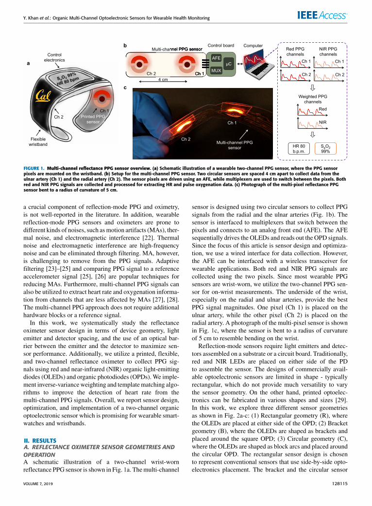
Reflection-mode sensors require light emitters and detec-tors assembled on a substrate or a circuit board. Traditionally,red and NIR LEDs are placed on either side of the PDto assemble the sensor. The designs of commercially avail-able optoelectronic sensors are limited in shape - typicallyrectangular, which do not provide much versatility to varythe sensor geometry. On the other hand, printed optoelec-tronics can be fabricated in various shapes and sizes [29].In this work, we explore three different sensor geometriesas shown in Fig. 2a-c: (1) Rectangular geometry (R), wherethe OLEDs are placed at either side of the OPD; (2) Bracketgeometry (B), where the OLEDs are shaped as brackets andplaced around the square OPD; (3) Circular geometry (C),where the OLEDs are shaped as block arcs and placed aroundthe circular OPD. The rectangular sensor design is chosento represent conventional sensors that use side-by-side opto-electronics placement. The bracket and the circular sensor
VOLUME 7, 2019 128115
Y. Khan et al.: Organic Multi-Channel Optoelectronic Sensors for Wearable Health Monitoring
FIGURE 2. Reflectance PPG sensor design and placement on the wrist. (a-c) Different sensor geometries with the same active areas.(a) Rectangular geometry (R), where the OLEDs are placed at either side of the OPD. (b) Bracket geometry (B), where the OLEDs are shaped asbrackets and placed around the square OPD. (c) Circular geometry (C), where the OLEDs are shaped as block arcs and placed around the circularOPD. (d) Photograph of the printed reflectance oximeter sensor placed on the underside of the wrist. The radial and ulnar artery sensing locationsare marked to show sensor placement locations. The inset shows a circular sensor with red and NIR OLEDs on the top and the bottom side of theOPD, respectively. (e) Normalized electroluminescence (EL) of the red (red line) and NIR (peach line) OLEDs and EQE of the OPD (brick line). TheOPD shows similar EQE at both red and NIR wavelengths.
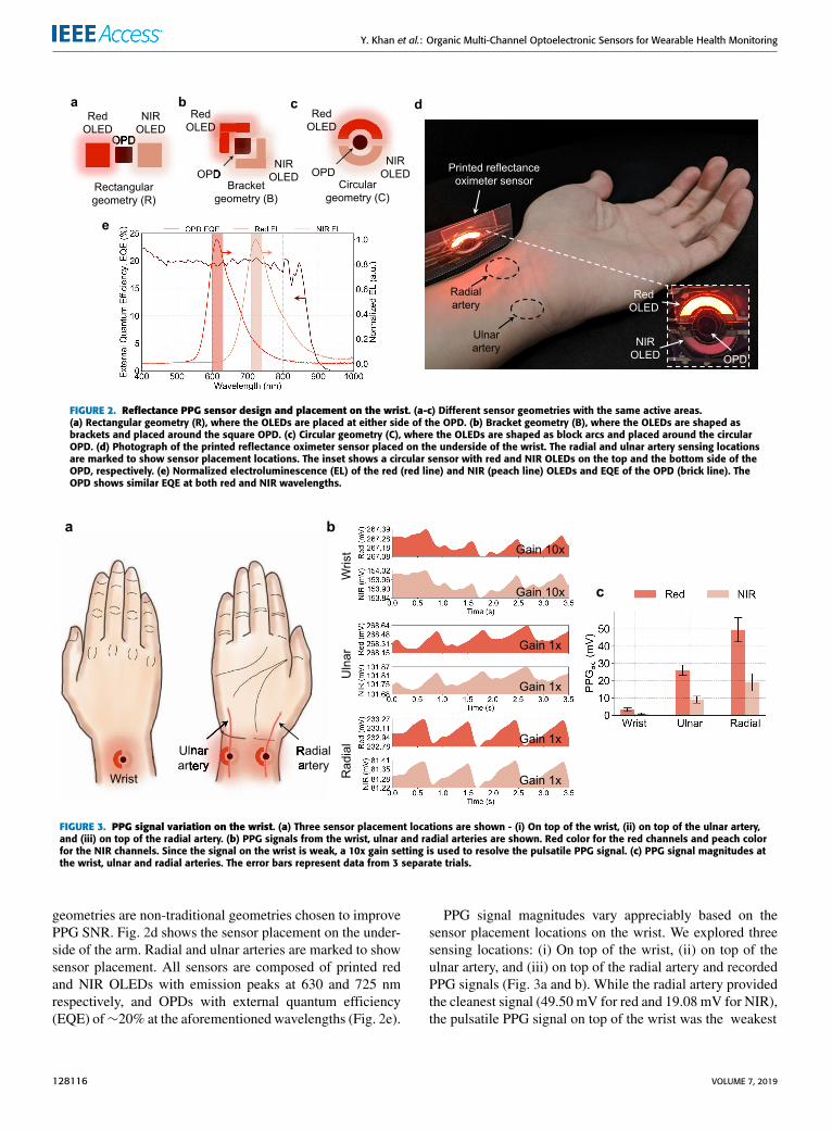
FIGURE 3. PPG signal variation on the wrist. (a) Three sensor placement locations are shown - (i) On top of the wrist, (ii) on top of the ulnar artery,and (iii) on top of the radial artery. (b) PPG signals from the wrist, ulnar and radial arteries are shown. Red color for the red channels and peach colorfor the NIR channels. Since the signal on the wrist is weak, a 10x gain setting is used to resolve the pulsatile PPG signal. (c) PPG signal magnitudes atthe wrist, ulnar and radial arteries. The error bars represent data from 3 separate trials.
geometries are non-traditional geometries chosen to improvePPG SNR. Fig. 2d shows the sensor placement on the under-side of the arm. Radial and ulnar arteries are marked to showsensor placement. All sensors are composed of printed redand NIR OLEDs with emission peaks at 630 and 725 nmrespectively, and OPDs with external quantum efficiency(EQE) of∼20% at the aforementioned wavelengths (Fig. 2e).
PPG signal magnitudes vary appreciably based on thesensor placement locations on the wrist. We explored threesensing locations: (i) On top of the wrist, (ii) on top of theulnar artery, and (iii) on top of the radial artery and recordedPPG signals (Fig. 3a and b). While the radial artery providedthe cleanest signal (49.50 mV for red and 19.08 mV for NIR),the pulsatile PPG signal on top of the wrist was the weakest
128116 VOLUME 7, 2019
Y. Khan et al.: Organic Multi-Channel Optoelectronic Sensors for Wearable Health Monitoring
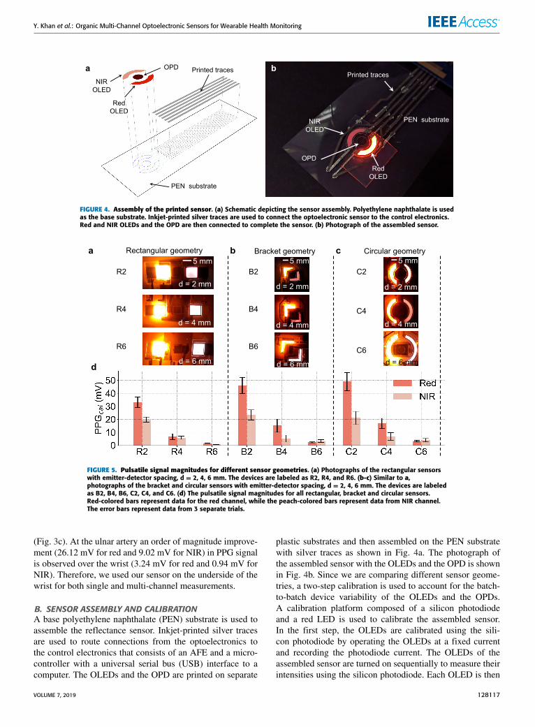
FIGURE 4. Assembly of the printed sensor. (a) Schematic depicting the sensor assembly. Polyethylene naphthalate is usedas the base substrate. Inkjet-printed silver traces are used to connect the optoelectronic sensor to the control electronics.Red and NIR OLEDs and the OPD are then connected to complete the sensor. (b) Photograph of the assembled sensor.
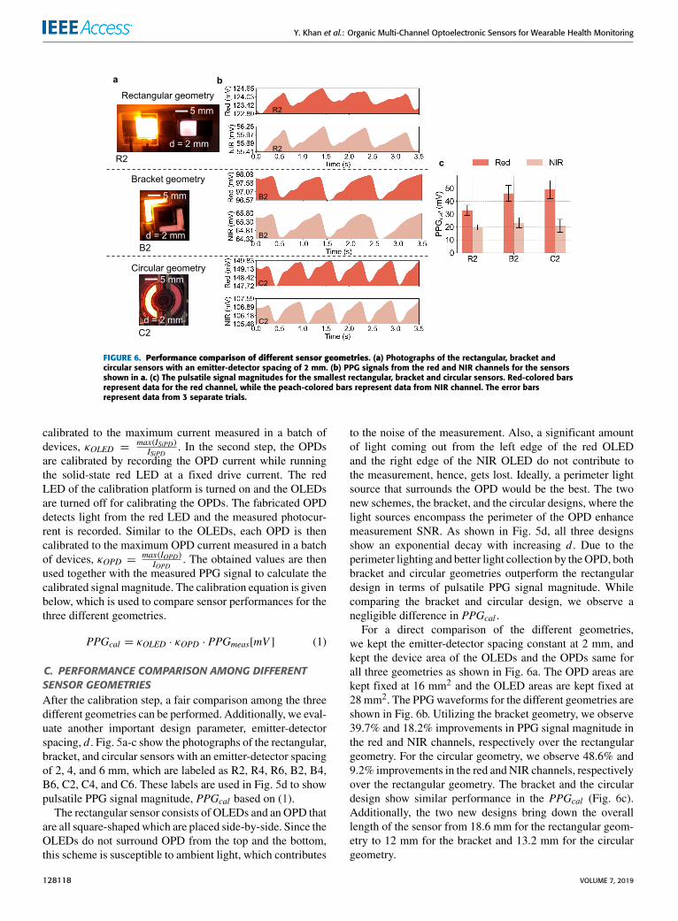
FIGURE 5. Pulsatile signal magnitudes for different sensor geometries. (a) Photographs of the rectangular sensorswith emitter-detector spacing, d = 2, 4, 6 mm. The devices are labeled as R2, R4, and R6. (b-c) Similar to a,photographs of the bracket and circular sensors with emitter-detector spacing, d = 2, 4, 6 mm. The devices are labeledas B2, B4, B6, C2, C4, and C6. (d) The pulsatile signal magnitudes for all rectangular, bracket and circular sensors.Red-colored bars represent data for the red channel, while the peach-colored bars represent data from NIR channel.The error bars represent data from 3 separate trials.
(Fig. 3c). At the ulnar artery an order of magnitude improve-ment (26.12 mV for red and 9.02 mV for NIR) in PPG signalis observed over the wrist (3.24 mV for red and 0.94 mV forNIR). Therefore, we used our sensor on the underside of thewrist for both single and multi-channel measurements.
B. SENSOR ASSEMBLY AND CALIBRATIONA base polyethylene naphthalate (PEN) substrate is used toassemble the reflectance sensor. Inkjet-printed silver tracesare used to route connections from the optoelectronics tothe control electronics that consists of an AFE and a micro-controller with a universal serial bus (USB) interface to acomputer. The OLEDs and the OPD are printed on separate
plastic substrates and then assembled on the PEN substratewith silver traces as shown in Fig. 4a. The photograph ofthe assembled sensor with the OLEDs and the OPD is shownin Fig. 4b. Since we are comparing different sensor geome-tries, a two-step calibration is used to account for the batch-to-batch device variability of the OLEDs and the OPDs.A calibration platform composed of a silicon photodiodeand a red LED is used to calibrate the assembled sensor.In the first step, the OLEDs are calibrated using the sili-con photodiode by operating the OLEDs at a fixed currentand recording the photodiode current. The OLEDs of theassembled sensor are turned on sequentially to measure theirintensities using the silicon photodiode. Each OLED is then
VOLUME 7, 2019 128117
Y. Khan et al.: Organic Multi-Channel Optoelectronic Sensors for Wearable Health Monitoring
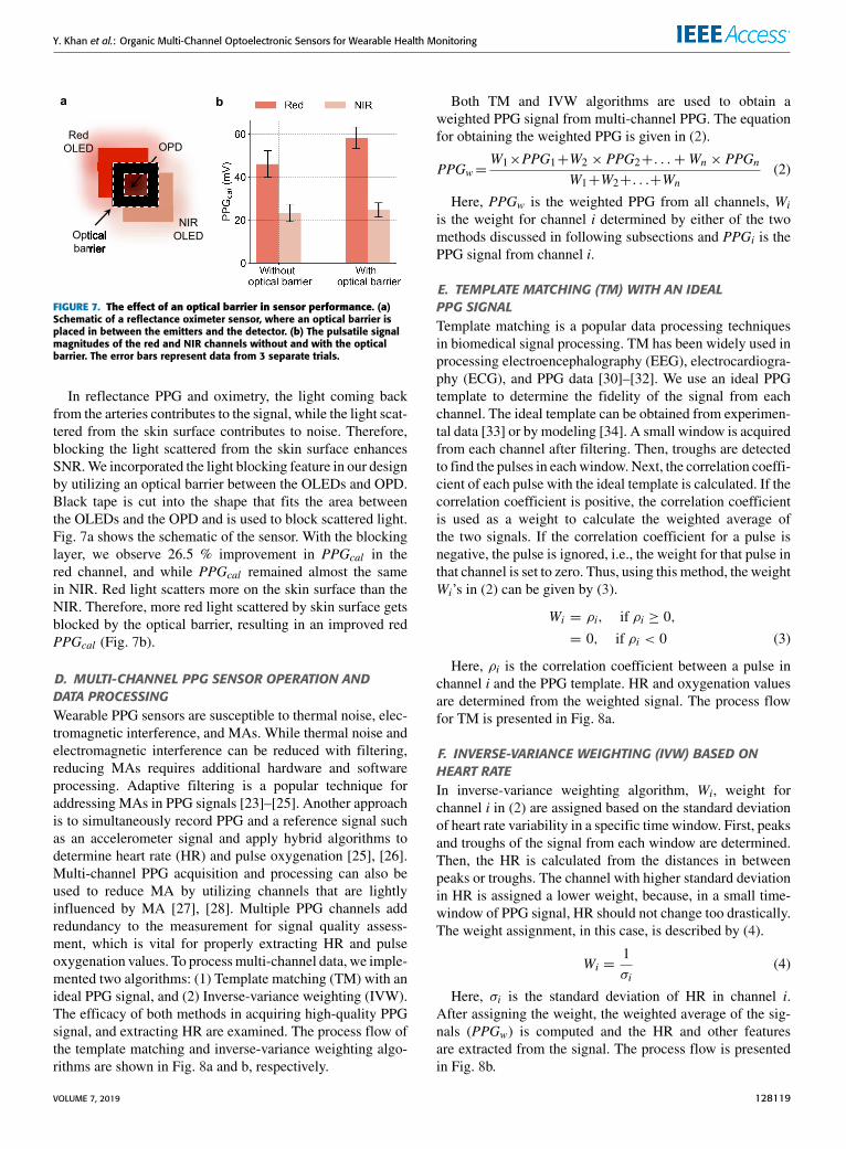
FIGURE 6. Performance comparison of different sensor geometries. (a) Photographs of the rectangular, bracket andcircular sensors with an emitter-detector spacing of 2 mm. (b) PPG signals from the red and NIR channels for the sensorsshown in a. (c) The pulsatile signal magnitudes for the smallest rectangular, bracket and circular sensors. Red-colored barsrepresent data for the red channel, while the peach-colored bars represent data from NIR channel. The error barsrepresent data from 3 separate trials.
calibrated to the maximum current measured in a batch ofdevices, κOLED =
max(ISiPD)ISiPD
. In the second step, the OPDsare calibrated by recording the OPD current while runningthe solid-state red LED at a fixed drive current. The redLED of the calibration platform is turned on and the OLEDsare turned off for calibrating the OPDs. The fabricated OPDdetects light from the red LED and the measured photocur-rent is recorded. Similar to the OLEDs, each OPD is thencalibrated to the maximum OPD current measured in a batchof devices, κOPD =
max(IOPD)IOPD
. The obtained values are thenused together with the measured PPG signal to calculate thecalibrated signal magnitude. The calibration equation is givenbelow, which is used to compare sensor performances for thethree different geometries.
PPGcal = κOLED · κOPD · PPGmeas[mV ] (1)
C. PERFORMANCE COMPARISON AMONG DIFFERENTSENSOR GEOMETRIESAfter the calibration step, a fair comparison among the threedifferent geometries can be performed. Additionally, we eval-uate another important design parameter, emitter-detectorspacing, d . Fig. 5a-c show the photographs of the rectangular,bracket, and circular sensors with an emitter-detector spacingof 2, 4, and 6 mm, which are labeled as R2, R4, R6, B2, B4,B6, C2, C4, and C6. These labels are used in Fig. 5d to showpulsatile PPG signal magnitude, PPGcal based on (1).The rectangular sensor consists of OLEDs and an OPD that
are all square-shapedwhich are placed side-by-side. Since theOLEDs do not surround OPD from the top and the bottom,this scheme is susceptible to ambient light, which contributes
to the noise of the measurement. Also, a significant amountof light coming out from the left edge of the red OLEDand the right edge of the NIR OLED do not contribute tothe measurement, hence, gets lost. Ideally, a perimeter lightsource that surrounds the OPD would be the best. The twonew schemes, the bracket, and the circular designs, where thelight sources encompass the perimeter of the OPD enhancemeasurement SNR. As shown in Fig. 5d, all three designsshow an exponential decay with increasing d . Due to theperimeter lighting and better light collection by theOPD, bothbracket and circular geometries outperform the rectangulardesign in terms of pulsatile PPG signal magnitude. Whilecomparing the bracket and circular design, we observe anegligible difference in PPGcal .
For a direct comparison of the different geometries,we kept the emitter-detector spacing constant at 2 mm, andkept the device area of the OLEDs and the OPDs same forall three geometries as shown in Fig. 6a. The OPD areas arekept fixed at 16 mm2 and the OLED areas are kept fixed at28 mm2. The PPGwaveforms for the different geometries areshown in Fig. 6b. Utilizing the bracket geometry, we observe39.7% and 18.2% improvements in PPG signal magnitude inthe red and NIR channels, respectively over the rectangulargeometry. For the circular geometry, we observe 48.6% and9.2% improvements in the red andNIR channels, respectivelyover the rectangular geometry. The bracket and the circulardesign show similar performance in the PPGcal (Fig. 6c).Additionally, the two new designs bring down the overalllength of the sensor from 18.6 mm for the rectangular geom-etry to 12 mm for the bracket and 13.2 mm for the circulargeometry.
128118 VOLUME 7, 2019
Y. Khan et al.: Organic Multi-Channel Optoelectronic Sensors for Wearable Health Monitoring
FIGURE 7. The effect of an optical barrier in sensor performance. (a)Schematic of a reflectance oximeter sensor, where an optical barrier isplaced in between the emitters and the detector. (b) The pulsatile signalmagnitudes of the red and NIR channels without and with the opticalbarrier. The error bars represent data from 3 separate trials.
In reflectance PPG and oximetry, the light coming backfrom the arteries contributes to the signal, while the light scat-tered from the skin surface contributes to noise. Therefore,blocking the light scattered from the skin surface enhancesSNR.We incorporated the light blocking feature in our designby utilizing an optical barrier between the OLEDs and OPD.Black tape is cut into the shape that fits the area betweenthe OLEDs and the OPD and is used to block scattered light.Fig. 7a shows the schematic of the sensor. With the blockinglayer, we observe 26.5 % improvement in PPGcal in thered channel, and while PPGcal remained almost the samein NIR. Red light scatters more on the skin surface than theNIR. Therefore, more red light scattered by skin surface getsblocked by the optical barrier, resulting in an improved redPPGcal (Fig. 7b).
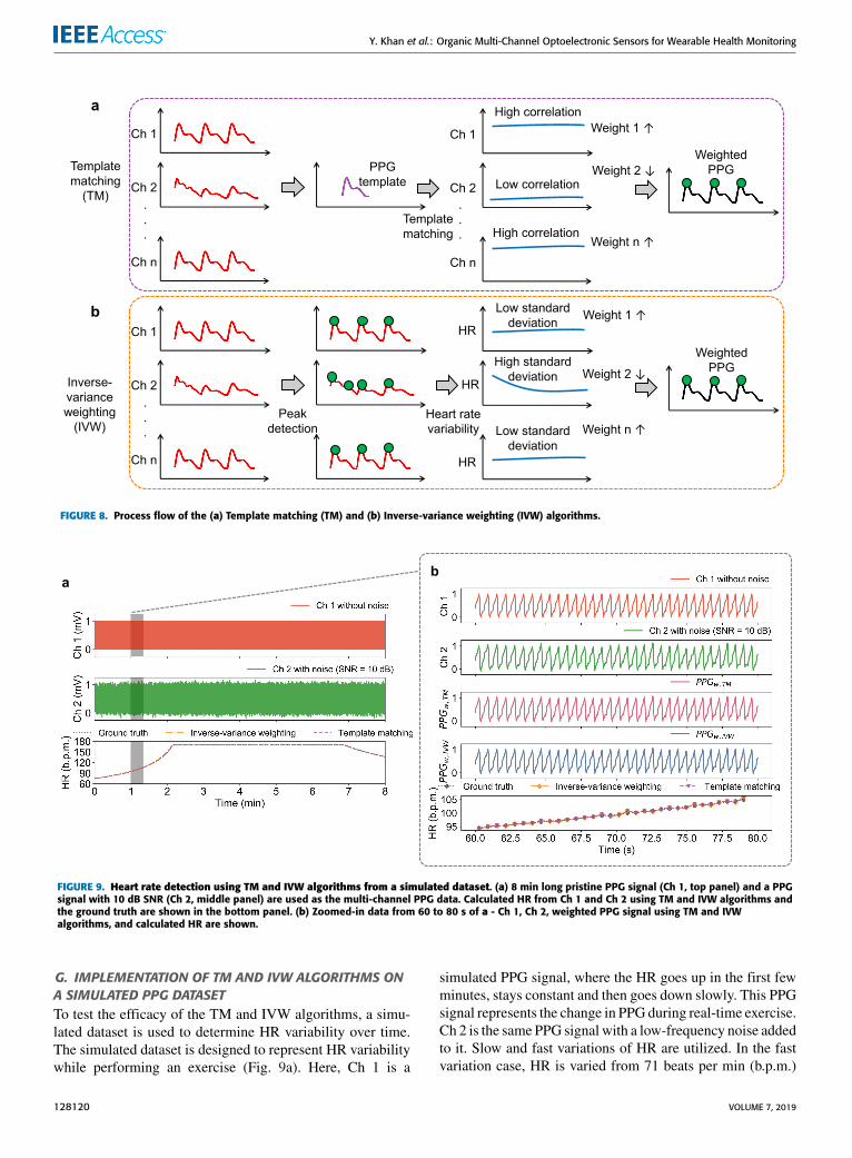
D. MULTI-CHANNEL PPG SENSOR OPERATION ANDDATA PROCESSINGWearable PPG sensors are susceptible to thermal noise, elec-tromagnetic interference, and MAs. While thermal noise andelectromagnetic interference can be reduced with filtering,reducing MAs requires additional hardware and softwareprocessing. Adaptive filtering is a popular technique foraddressing MAs in PPG signals [23]–[25]. Another approachis to simultaneously record PPG and a reference signal suchas an accelerometer signal and apply hybrid algorithms todetermine heart rate (HR) and pulse oxygenation [25], [26].Multi-channel PPG acquisition and processing can also beused to reduce MA by utilizing channels that are lightlyinfluenced by MA [27], [28]. Multiple PPG channels addredundancy to the measurement for signal quality assess-ment, which is vital for properly extracting HR and pulseoxygenation values. To processmulti-channel data, we imple-mented two algorithms: (1) Template matching (TM) with anideal PPG signal, and (2) Inverse-variance weighting (IVW).The efficacy of both methods in acquiring high-quality PPGsignal, and extracting HR are examined. The process flow ofthe template matching and inverse-variance weighting algo-rithms are shown in Fig. 8a and b, respectively.
Both TM and IVW algorithms are used to obtain aweighted PPG signal from multi-channel PPG. The equationfor obtaining the weighted PPG is given in (2).
PPGw=W1×PPG1+W2 × PPG2+. . .+Wn × PPGn
W1+W2+. . .+Wn(2)
Here, PPGw is the weighted PPG from all channels, Wiis the weight for channel i determined by either of the twomethods discussed in following subsections and PPGi is thePPG signal from channel i.
E. TEMPLATE MATCHING (TM) WITH AN IDEALPPG SIGNALTemplate matching is a popular data processing techniquesin biomedical signal processing. TM has been widely used inprocessing electroencephalography (EEG), electrocardiogra-phy (ECG), and PPG data [30]–[32]. We use an ideal PPGtemplate to determine the fidelity of the signal from eachchannel. The ideal template can be obtained from experimen-tal data [33] or by modeling [34]. A small window is acquiredfrom each channel after filtering. Then, troughs are detectedto find the pulses in eachwindow. Next, the correlation coeffi-cient of each pulse with the ideal template is calculated. If thecorrelation coefficient is positive, the correlation coefficientis used as a weight to calculate the weighted average ofthe two signals. If the correlation coefficient for a pulse isnegative, the pulse is ignored, i.e., the weight for that pulse inthat channel is set to zero. Thus, using this method, the weightWi’s in (2) can be given by (3).
Wi = ρi, if ρi ≥ 0,
= 0, if ρi < 0 (3)
Here, ρi is the correlation coefficient between a pulse inchannel i and the PPG template. HR and oxygenation valuesare determined from the weighted signal. The process flowfor TM is presented in Fig. 8a.
F. INVERSE-VARIANCE WEIGHTING (IVW) BASED ONHEART RATEIn inverse-variance weighting algorithm, Wi, weight forchannel i in (2) are assigned based on the standard deviationof heart rate variability in a specific time window. First, peaksand troughs of the signal from each window are determined.Then, the HR is calculated from the distances in betweenpeaks or troughs. The channel with higher standard deviationin HR is assigned a lower weight, because, in a small time-window of PPG signal, HR should not change too drastically.The weight assignment, in this case, is described by (4).
Wi =1σi
(4)
Here, σi is the standard deviation of HR in channel i.After assigning the weight, the weighted average of the sig-nals (PPGw) is computed and the HR and other featuresare extracted from the signal. The process flow is presentedin Fig. 8b.
VOLUME 7, 2019 128119
Y. Khan et al.: Organic Multi-Channel Optoelectronic Sensors for Wearable Health Monitoring
FIGURE 8. Process flow of the (a) Template matching (TM) and (b) Inverse-variance weighting (IVW) algorithms.
FIGURE 9. Heart rate detection using TM and IVW algorithms from a simulated dataset. (a) 8 min long pristine PPG signal (Ch 1, top panel) and a PPGsignal with 10 dB SNR (Ch 2, middle panel) are used as the multi-channel PPG data. Calculated HR from Ch 1 and Ch 2 using TM and IVW algorithms andthe ground truth are shown in the bottom panel. (b) Zoomed-in data from 60 to 80 s of a - Ch 1, Ch 2, weighted PPG signal using TM and IVWalgorithms, and calculated HR are shown.
G. IMPLEMENTATION OF TM AND IVW ALGORITHMS ONA SIMULATED PPG DATASETTo test the efficacy of the TM and IVW algorithms, a simu-lated dataset is used to determine HR variability over time.The simulated dataset is designed to represent HR variabilitywhile performing an exercise (Fig. 9a). Here, Ch 1 is a
simulated PPG signal, where the HR goes up in the first fewminutes, stays constant and then goes down slowly. This PPGsignal represents the change in PPG during real-time exercise.Ch 2 is the same PPG signal with a low-frequency noise addedto it. Slow and fast variations of HR are utilized. In the fastvariation case, HR is varied from 71 beats per min (b.p.m.)
128120 VOLUME 7, 2019
Y. Khan et al.: Organic Multi-Channel Optoelectronic Sensors for Wearable Health Monitoring
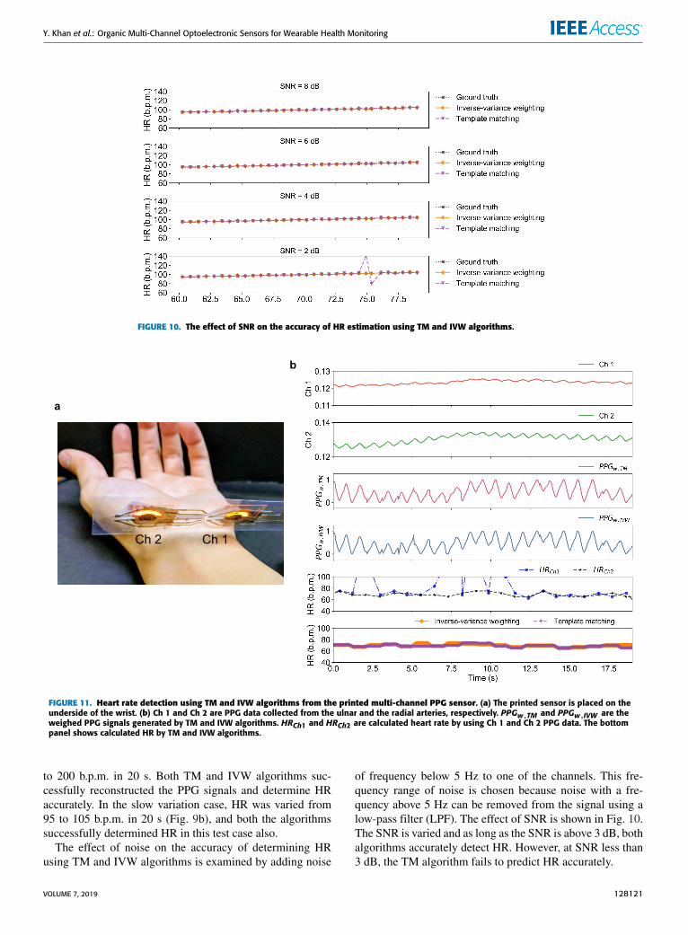
FIGURE 10. The effect of SNR on the accuracy of HR estimation using TM and IVW algorithms.
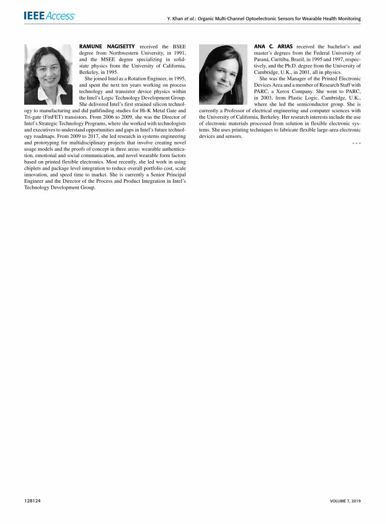
FIGURE 11. Heart rate detection using TM and IVW algorithms from the printed multi-channel PPG sensor. (a) The printed sensor is placed on theunderside of the wrist. (b) Ch 1 and Ch 2 are PPG data collected from the ulnar and the radial arteries, respectively. PPGw,TM and PPGw,IVW are theweighed PPG signals generated by TM and IVW algorithms. HRCh1 and HRCh2 are calculated heart rate by using Ch 1 and Ch 2 PPG data. The bottompanel shows calculated HR by TM and IVW algorithms.
to 200 b.p.m. in 20 s. Both TM and IVW algorithms suc-cessfully reconstructed the PPG signals and determine HRaccurately. In the slow variation case, HR was varied from95 to 105 b.p.m. in 20 s (Fig. 9b), and both the algorithmssuccessfully determined HR in this test case also.
The effect of noise on the accuracy of determining HRusing TM and IVW algorithms is examined by adding noise
of frequency below 5 Hz to one of the channels. This fre-quency range of noise is chosen because noise with a fre-quency above 5 Hz can be removed from the signal using alow-pass filter (LPF). The effect of SNR is shown in Fig. 10.The SNR is varied and as long as the SNR is above 3 dB, bothalgorithms accurately detect HR. However, at SNR less than3 dB, the TM algorithm fails to predict HR accurately.
VOLUME 7, 2019 128121

Y. Khan et al.: Organic Multi-Channel Optoelectronic Sensors for Wearable Health Monitoring
TABLE 1. Heart rate calculated from a literature dataset [25] usingtemplate matching and inverse-variance weighting algorithms.
In addition to the simulated dataset, we used three sets ofPPG dual-channel data reported by Zhang et al. [25] to testthe efficacy of the TM and IVW algorithms. The results aresummarized in Table 1. For the datasets, I and III the HRcalculated using both methods are close to the ground truthHR, i.e., within 2 b.p.m. However, in dataset II, both channelsare severely affected byMA, so the calculated HRs are furtheraway from ground truth HR. For accurate detection of HR,at least one of the channels should be minimally affected byMA so that the PPG pulses are recognizable.
H. IMPLEMENTATION OF TM AND IVW ALGORITHMS ONTHE PRINTED MULTI-CHANNEL PPG SENSOR DATAAfter validating the TM and IVW algorithms on the simu-lated and literature datasets, we employed both methods forprocessing the data collected by the printed multi-channelPPG sensor. The sensor is placed on the underside of thewrist, where Ch 1 collects data from the ulnar artery andCh 2 collects data from the radial artery (Fig. 11a and b,top two panels). The weighed PPG signals generated byTM and IVW algorithms are shown in panel 3 and 4 ofFig. 11b. Here, the signal magnitude of Ch 1 is weakercompared to Ch 2. Therefore, HR calculated using only usingCh 1 PPG signal demonstrates significant variation (panel 5of Fig. 11b). After implementing TM and IVW algorithms,accurate detection of HR is observed for both the algorithms(bottom panel of Fig. 11b), demonstrating the feasibilityof using these two methods for wearable PPG sensors andoximeters.
III. DISCUSSIONBy utilizing the versatility of printed electronics, opto-electronic sensors for PPG and oximetry are fabricated indifferent shapes and sizes. In this work, we utilized non-conventional geometries such as bracket and circular designsto improve sensor performance. The new sensor geometriesdemonstrated a clear improvement over the conventionalrectangular sensor design. Moreover, we used a wearabletwo-channel PPG sensor to add redundancy to the measure-ment and demonstrated the effectiveness of inverse-varianceweighting and template matching algorithms to improve thedetection of heart rate from the multi-channel PPG signals.The new sensor geometries not only improved the PPG sig-nal magnitudes but also decreased the overall sensor lengthand reduced power consumption. These sensor designs cou-pled with multi-channel redundancy can be incorporated into
wrist-worn devices, making them extremely promising forwearable reflectance PPG and oximetry.
ACKNOWLEDGMENTThe authors thank David Rosales, Claire Lochner, GianlucaBovo, Nir Yaacobi-Gross, Chris Newsome, Richard Wilson,and Sifat Muin for helpful technical discussions. YasserKhan, Donggeon Han, Jonathan Ting, and Maruf Ahmedcontributed equally to this work.
REFERENCES[1] J. G. Webster, Design of Pulse Oximeters. Boca Raton, FL, USA:
CRC Press, 1997.[2] Y. Khan, D. Han, A. Pierre, J. Ting, X. Wang, C. M. Lochner, G. Bovo,
N. Yaacobi-Gross, C. Newsome, R. Wilson, and A. C. Arias, ‘‘A flexibleorganic reflectance oximeter array,’’ Proc. Nat. Acad. Sci. USA, vol. 115,no. 47, pp. E11015–E11024, 2018.
[3] C. M. Lochner, Y. Khan, A. Pierre, and A. C. Arias, ‘‘All-organic opto-electronic sensor for pulse oximetry,’’ Nature Commun., vol. 5, p. 5745,Dec. 2014.
[4] T. Q. Trung and N.-E. Lee, ‘‘Flexible and stretchable physical sensorintegrated platforms for wearable human-activity monitoring and personalhealthcare,’’ Adv. Mater., vol. 28, no. 22, pp. 4338–4372, 2016.
[5] S. Choi, H. Lee, R. Ghaffari, T. Hyeon, and D.-H. Kim, ‘‘Recent advancesin flexible and stretchable bio-electronic devices integrated with nanoma-terials,’’ Adv. Mater., vol. 28, no. 22, pp. 4203–4218, 2016.
[6] T. Someya, Z. Bao, and G. G. Malliaras, ‘‘The rise of plastic bioelectron-ics,’’ Nature, vol. 540, pp. 379–385, Dec. 2016.
[7] M. Poliks, J. Turner, K. Ghose, Z. Jin, M. Garg, Q. Gui, A. Arias, Y. Kahn,M. Schadt, and F. Egitto, ‘‘A wearable flexible hybrid electronics ECGmonitor,’’ in Proc. IEEE 66th Electron. Compon. Technol. Conf. (ECTC),May/Jun. 2016, pp. 1623–1631.
[8] V. Soman, Y. Khan, M. Zabran, M. Schadt, P. Hart, M. Shay, F. Egitto,K. Papathomas, N. A. D. Yamamoto, D. Han, A. C. Arias, K. Ghose,M. D. Poliks, J. N. Turner, ‘‘Reliability challenges in fabrication of flexiblehybrid electronics for human performancemonitors: A system level study,’’IEEE Trans. Compon., Packag. Manuf. Technol., to be published.
[9] S. Jung, S. Hong, J. Kim, S. Lee, T. Hyeon, M. Lee, and D.-H. Kim,‘‘Wearable fall detector using integrated sensors and energy devices,’’ Sci.Rep., vol. 5, Nov. 2015, Art. no. 17081.
[10] S. Choi, S. I. Han, D. Jung, H. J. Hwang, C. Lim, S. Bae, O. K. Park,C. M. Tschabrunn, M. Lee, S. Y. Bae, J. W. Yu, J. H. Ryu, S.-W. Lee,K. Park, P. M. Kang, W. B. Lee, R. Nezafat, T. Hyeon, and D.-H. Kim,‘‘Highly conductive, stretchable and biocompatible Ag–Au core–sheathnanowire composite for wearable and implantable bioelectronics,’’ NatureNanotechnol., vol. 13, pp. 1048–1056, 2018.
[11] M. F. Farooqui and A. Shamim, ‘‘Low cost inkjet printed smart bandagefor wireless monitoring of chronic wounds,’’ Sci. Rep., vol. 6, Jun. 2016,Art. no. 28949.
[12] J. M. Nassar, K. Mishra, K. Lau, A. A. Aguirre-Pablo, and M. M. Hussain,‘‘Recyclable nonfunctionalized paper-based ultralow-cost wearable healthmonitoring system,’’ Adv. Mater. Technol., vol. 2, no. 4, 2017,Art. no. 1600228.
[13] L. Engel, C. Liu, N. M. Hemed, Y. Khan, A. C. Arias,Y. Shacham-Diamand, S. Krylov, and L. Lin, ‘‘Local electrochemicalcontrol of hydrogel microactuators in microfluidics,’’ J. Micromech.Microeng., vol. 28, no. 10, 2018, Art. no. 105005.
[14] A. Moin, A. Zhou, A. Rahimi, S. Benatti, A. Menon, S. Tamakloe,J. Ting, N. Yamamoto, Y. Khan, F. Burghardt, L. Benini, A. C. Arias, andJ. M. Rabaey, ‘‘An EMG gesture recognition system with flexible high-density sensors and brain-inspired high-dimensional classifier,’’ in Proc.IEEE Int. Symp. Circuits Syst. (ISCAS), May 2018, pp. 1–5.
[15] A. E. Ostfeld, A. M. Gaikwad, Y. Khan, and A. C. Arias, ‘‘High-performance flexible energy storage and harvesting system for wearableelectronics,’’ Sci. Rep., vol. 6, May 2016, Art. no. 26122.
[16] A. Thielens, I. Deckman, R. Aminzadeh, A. C. Arias, and J. M. Rabaey,‘‘Fabrication and characterization of flexible spray-coated antennas,’’IEEE Access, vol. 6, pp. 62050–62061, 2018.
128122 VOLUME 7, 2019

Y. Khan et al.: Organic Multi-Channel Optoelectronic Sensors for Wearable Health Monitoring
[17] T. Yokota, P. Zalar, M. Kaltenbrunner, H. Jinno, N. Matsuhisa,H. Kitanosako, Y. Tachibana, W. Yukita, M. Koizumi, and T. Someya,‘‘Ultraflexible organic photonic skin,’’ Sci. Adv., vol. 2, no. 4, Apr. 2016,Art. no. e1501856.
[18] J. Kim et al., ‘‘Battery-free, stretchable optoelectronic systems for wire-less optical characterization of the skin,’’ Sci. Adv., vol. 2, no. 8, 2016,Art. no. e1600418.
[19] D. Han, Y. Khan, J. Ting, S. M. King, N. Yaacobi-Gross, M. J. Humphries,C. J. Newsome, and A. C. Arias, ‘‘Flexible blade-coated multicolor poly-mer light-emitting diodes for optoelectronic sensors,’’ Adv. Mater., vol. 29,no. 22, Jun. 2017, Art. no. 1606206.
[20] D. Yin, N.-R. Jiang, Y.-F. Liu, X.-L. Zhang, A.-W. Li, J. Feng,and H.-B. Sun, ‘‘Mechanically robust stretchable organic optoelectronicdevices built using a simple and universal stencil-pattern transferring tech-nology,’’ Light, Sci. Appl., vol. 7, no. 1, 2018, Art. no. 35.
[21] H. Lee, E. Kim, Y. Lee, H. Kim, J. Lee, M. Kim, H.-J. Yoo, and S. Yoo,‘‘Toward all-day wearable health monitoring: An ultralow-power, reflec-tive organic pulse oximetry sensing patch,’’ Sci. Adv., vol. 4, no. 11, 2018,Art. no. eaas9530.
[22] M. R. Ram, K. V. Madhav, E. H. Krishna, N. R. Komalla, and K. A. Reddy,‘‘A novel approach for motion artifact reduction in PPG signals basedon AS-LMS adaptive filter,’’ IEEE Trans. Instrum. Meas., vol. 61, no. 5,pp. 1445–1457, May 2012.
[23] F. Peng, Z. Zhang, X. Gou, H. Liu, and W. Wang, ‘‘Motion artifactremoval from photoplethysmographic signals by combining temporallyconstrained independent component analysis and adaptive filter,’’ Biomed.Eng. OnLine, vol. 13, no. 1, p. 50, 2014.
[24] H. Han, M.-J. Kim, and J. Kim, ‘‘Development of real-time motion arti-fact reduction algorithm for a wearable photoplethysmography,’’ in Proc.29th IEEE Annu. Int. Conf. Eng. Med. Biol. Soc. (EMBS), Aug. 2007,pp. 1538–1541.
[25] Z. Zhang, Z. Pi, and B. Liu, ‘‘TROIKA: A general framework for heartrate monitoring using wrist-type photoplethysmographic signals duringintensive physical exercise,’’ IEEE Trans. Biomed. Eng., vol. 62, no. 2,pp. 522–531, Feb. 2015.
[26] Z. Zhang, ‘‘Heart rate monitoring from wrist-type photoplethysmo-graphic (PPG) signals during intensive physical exercise,’’ in Proc.IEEE Global Conf. Signal Inf. Process. (GlobalSIP), Dec. 2014,pp. 698–702.
[27] S.-T. Lin, W.-H. Chen, and Y.-H. Lin, ‘‘A pulse rate detection method formouse application based on multi-PPG sensors,’’ Sensors, vol. 17, no. 7,p. 1628, 2017.
[28] K. M. Warren, J. R. Harvey, K. H. Chon, and Y. Mendelson, ‘‘Improvingpulse rate measurements during random motion using a wearable multi-channel reflectance photoplethysmograph,’’ Sensors, vol. 16, no. 3, p. 342,2016.
[29] D. Han, Y. Khan, K. Gopalan, A. Pierre, and A. C. Arias, ‘‘Emis-sion area patterning of organic light-emitting diodes (OLEDs) viaprinted dielectrics,’’ Adv. Funct. Mater., vol. 28, no. 37, 2018,Art. no. 1802986.
[30] H. Qu and J. Gotman, ‘‘A patient-specific algorithm for the detec-tion of seizure onset in long-term EEG monitoring: Possible useas a warning device,’’ IEEE Trans. Biomed. Eng., vol. 44, no. 2,pp. 115–122, Feb. 1997.
[31] M. Baumert, V. Starc, and A. Porta, ‘‘Conventional QT variabilitymeasurement vs. template matching techniques: Comparison of perfor-mance using simulated and real ECG,’’ PLoS ONE, vol. 7, no. 7, 2012,Art. no. e41920.
[32] C. Orphanidou, T. Bonnici, P. Charlton, D. Clifton, D. Vallance, andL. Tarassenko, ‘‘Signal-quality indices for the electrocardiogram andphotoplethysmogram: Derivation and applications to wireless monitor-ing,’’ IEEE J. Biomed. Health Informat., vol. 19, no. 3, pp. 832–838,May 2015.
[33] Y. Liang, M. Elgendi, Z. Chen, and R. Ward, ‘‘An optimal filterfor short photoplethysmogram signals,’’ Sci. Data, vol. 5, May 2018,Art. no. 180076.
[34] F. Rundo, S. Conoci, A. Ortis, and S. Battiato, ‘‘An advanced bio-inspired photoplethysmography (PPG) and ECG pattern recognitionsystem for medical assessment,’’ Sensors, vol. 18, no. 2, p. 405,Jan. 2018.
YASSER KHAN received the B.S. degree in elec-trical engineering from The University of Texasat Dallas, in 2010, the M.S. degree in electri-cal engineering from the King Abdullah Univer-sity of Science and Technology, in 2012, and thePh.D. degree in electrical engineering and com-puter sciences from the University of California,Berkeley, in 2018, from Professor Ana ClaudiaArias’ research group. He is currently a Postdoc-toral Scholar with Stanford University, advised by
Professor Zhenan Bao in chemical engineering and Professor Boris Mur-mann in electrical engineering. His research interests include wearable med-ical devices, with an emphasis on skin-like soft sensor systems. His researchexperience includes internships at Oxford University, Stanford University,and Zyvex Labs in Texas.
DONGGEON HAN received the bachelor’s, mas-ter’s, and Ph.D. degrees from the Korea AdvancedInstitute of Science and Technology, all in elec-trical engineering, in 2009, 2011, and 2015,respectively.
He was a Postdoctoral Researcher with theDepartment of Electrical Engineering and Com-puter Sciences, University of California, Berkeley,from 2015 to 2018. He conducted research onprinted optoelectronic sensors and devices. He iscurrently a Hardware Engineer with Apple.
JONATHAN TING received the B.S. degree inelectrical engineering from the Georgia Instituteof Technology, in 2015. He is currently pursuingthe Ph.D. degree with the Department of ElectricalEngineering and Computer Sciences, University ofCalifornia, Berkeley, from Professor Ana ClaudiaArias’ research group. His research interests pri-marily include flexible wearable sensors, with afocus in printed optoelectronics and biosensors.
MARUF AHMED received the bachelor’s andmaster’s degrees in electrical and electronic engi-neering from the Bangladesh University of Engi-neering and Technology, in 2013 and 2016,respectively. In undergraduate research, he hasinvestigated the feasibility of quantum cascadestructures for thermophotovoltaic energy harvest-ing application. In his M.Sc. thesis, he has workedon III–V material-based type II quantum well-infrared photodetectors. His current research inter-
ests include printed organic photodiodes and phototransistors.
VOLUME 7, 2019 128123
Y. Khan et al.: Organic Multi-Channel Optoelectronic Sensors for Wearable Health Monitoring
RAMUNE NAGISETTY received the BSEEdegree from Northwestern University, in 1991,and the MSEE degree specializing in solid-state physics from the University of California,Berkeley, in 1995.
She joined Intel as a Rotation Engineer, in 1995,and spent the next ten years working on processtechnology and transistor device physics withinthe Intel’s Logic Technology Development Group.She delivered Intel’s first strained silicon technol-
ogy to manufacturing and did pathfinding studies for Hi-K Metal Gate andTri-gate (FinFET) transistors. From 2006 to 2009, she was the Director ofIntel’s Strategic Technology Programs, where she worked with technologistsand executives to understand opportunities and gaps in Intel’s future technol-ogy roadmaps. From 2009 to 2017, she led research in systems engineeringand prototyping for multidisciplinary projects that involve creating novelusage models and the proofs of concept in three areas: wearable authentica-tion, emotional and social communication, and novel wearable form factorsbased on printed flexible electronics. Most recently, she led work in usingchiplets and package level integration to reduce overall portfolio cost, scaleinnovation, and speed time to market. She is currently a Senior PrincipalEngineer and the Director of the Process and Product Integration in Intel’sTechnology Development Group.
ANA C. ARIAS received the bachelor’s andmaster’s degrees from the Federal University ofParaná, Curitiba, Brazil, in 1995 and 1997, respec-tively, and the Ph.D. degree from the University ofCambridge, U.K., in 2001, all in physics.
She was the Manager of the Printed ElectronicDevices Area and amember of Research Staff withPARC, a Xerox Company. She went to PARC,in 2003, from Plastic Logic, Cambridge, U.K.,where she led the semiconductor group. She is
currently a Professor of electrical engineering and computer sciences withthe University of California, Berkeley. Her research interests include the useof electronic materials processed from solution in flexible electronic sys-tems. She uses printing techniques to fabricate flexible large-area electronicdevices and sensors.
128124 VOLUME 7, 2019