Embed Size (px)
Citation preview
5
Development of Optoelectronic Sensors and Transceivers for Spacecraft Applications
José M. Sánchez-Pena, Carlos Marcos, Alberto Carrasco, Ricardo Vergaz and Ramón Zaera
Carlos III University of Madrid Spain
1. Introduction
The main goal of this chapter is to show several optoelectronic systems to be applied in two different interest areas of spacecraft technologies: mechanical testing and optical communications. In the first part of this chapter, we present a simple, cost-effective and robust microcontrolled optoelectronic system that is able to measure with a reasonable accuracy a wide range of projectile velocities for impact testing of aeronautic and aerospace structures. In the second part of this chapter, we review different approaches to optimize the performance of free-space optical communications (FSOC) systems such as architecture of transceivers, pointing and tracking subsystems, wavelength tunability, diffraction limit, photodetectors’ performance, among others. A great effort was made in the last decades to design advanced shielding to protect aircraft and spacecraft structures and to evaluate the damage on structures impacted by projectiles and meteoroids. Although numerical simulation has been increasingly adopted to analyze these problems, experimental testing is still a need to validate numerical codes and to obtain reliable information. The importance of taking measurements during an impact event is evident from the vast amount of work performed in this area. Among the variables that should be measured during the impact test, an accurate determination of the velocity of the projectile is obviously of great importance, since its square is related to the kinetic energy applied to the specimen. Many different measurement techniques have been used; however, the purpose of the next section is not an exhaustive review of the literature but to provide an overview of some typical measurement methods. Optical communication is a major issue in both guided and unguided modes of transmission. In optical fiber systems, losses can approach less tan 0.15 dB/km and and multi-Gbps data streams can be transmitted over tens of thousands of kilometers without electronic regeneration. In free-space systems, optical communication again has advantages. Smaller diameter transmitter and receiver apertures are needed to establish high date-rate communication links and, unlike the congested microwave bands, there is plenty of available spectrum. In addition, the narrow beam divergence of an optical system can be used to provide additional security by lowering the probability of detecting and intercepting the transmission. The advent of technologies such as the erbium-doped fiber amplifier (EDFA) which made the implementation of nearquantum limited receiver performance achievable and the
www.intechopen.com
Advances in Spacecraft Technologies
100
development of high-speed modulators and detectors provided the components necessary to carry out affordable and robust free-space optical communications (FSOC) for broadband applications (Chang, 2000). Further investments in optical beam steering technology extended the capabilities and possibilities of integrating FSOC on mobile platforms such as ground vehicles, airplanes, and satellites. Because of the complexity associated with phase or frequency modulation, current FSOC systems typically use intensity modulation with direct detection (IM/DD). Atmospheric turbulence can degrade the performance of free-space optical links, particularly over distances longer than 1 km. Due to inhomogeneities in the temperature and pressure of the atmosphere, variations of the refractive index along the transmission path can be produced. This effect can deteriorate the quality of the received image and can cause fluctuations in both the intensity and the phase of the received signal. These fluctuations can lead to an increase in the link error probability, limiting the performance of communication systems. Additionally, platform vibrations and misalignment of the transmitter and receiver telescopes can cause similar time-varying fades of received power. These fluctuations can be mitigated using different techniques (Henniger et al., 2003). Other optical correction techniques such as adaptive optics or spatial diversity can be employed to achieve a similar compensating effect (Andrews & Phillips, 2005).
2. Optoelectronic sensors: Velocity measurement methods and proposed system
2.1 Current measurement methods A great variety of sensors were used to estimate the velocity of projectiles. The most common measurement system is the chronograph (Paulter & Larson, 2009). In this kind of systems, the velocity of the projectile is calculated by dividing the base length, or the distance between two sensor locations, by the difference of the times when the projectile arrives at these locations. The type of sensor used to detect the passage of the solid makes the difference between chronographs. However, other kinds of systems were also used in the last decades. The simplest ones are the break-paper and the break-wire sensors. The first system leads commonly to a small number of faults, especially when the projectile is non-metallic. In the second one, more reliable than the first one, a thin wire is cut by the projectile. The main drawback of both systems is related to impacts at subsonic velocities: the pressure wave preceding the projectile causes stretching before breaking of the wire or bulging before tearing of the sheets. The base length then varies and this lead to an unknown error. Additionally, inductive sensors, radar Doppler and photographic systems have been also used to determine the velocity of a projectile, but all of them show some important limitations in terms of reliability, robustness, velocity range, performance-cost ratio, among others (Zukas et al, 1992). Inductive sensors are based on a circular open-coil sensor that is located surrounding the path of the projectile. When the projectile approaches, eddy currents are induced and the voltage output increases reaching a peak and then decreasing as the bullet leaves the coil. The system has to be calibrated and the gain setting has to be adjusted for each projectile material, size and shape by manually positioning it in the coil before the test. On the other hand, this type of sensor could not detect these projectiles made of non-conductive material, which would be an important drawback compared to other sensors. Doppler radar, also called continuous-wave radar, is another measurement system used for measuring the projectile speeds. Its working principle is based on an antenna that is aligned
www.intechopen.com
Development of Optoelectronic Sensors and Transceivers for Spacecraft Applications
101
to the projectile path and sends a continuous radio signal. The projectile reflects the pulses with a frequency shifted due to the Doppler effect, allowing it to produce a target frequency after being mixed with a sample of the transmit frequency. Doppler radar method and apparatus for measuring a projectile's muzzle velocity offers important benefits: good accuracy, simple set up, minimal risk of damage of equipment by stray bullets. An additional advantage is the possibility to measure, in some cases, the residual velocity of the projectile after perforating the target. Nevertheless, the cost of a conventional system is quite expensive as compared to chronographs. Photographic systems have also been used to determine the velocity of a projectile (Wilde et al, 1973). Since the event takes place quickly and time exposures should be extremely short (on the order of the microsecond or even shorter), ultra high speed cameras have to be used. In these, the high speed film usually remains stationary inside of a drum and sweeps the image across it by reflection from a rotating mirror or prism (Moss et al, 1995). Facing the film-based cameras, digital ultra high speed cameras passed through a striking development in the last decade. The appearing of highly light-sensitive mega-pixel CMOS sensors allowed acquiring images with an exposure time short enough to freeze the movement of the projectile. The easy-to operate approach of these cameras and the possibility to record long time periods facilitates the synchronization and triggering operations. Anyway, the high cost of analogical or digital cameras -and sometimes that of the lighting systems needed to illumine the projectile- means currently a great drawback. On the other hand, optical sensor applications are growing in mechanical testing. Continuous efforts for improving robustness in every step of optical sensor development recently resulted in using optical sensors in safety critical spacecraft applications.
2.2 Proposed system: configuration and working principle This section presents a microcontrolled opto-electronic system to measure on-line the
average velocity of a projectile impacting on aircraft and spacecraft structures. The projectile
velocity can vary in the range from subsonic to supersonic.
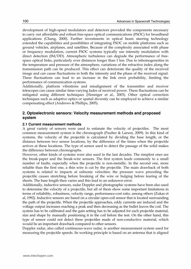
The measurement optical system provides the projectile velocity by measuring the time of
flight taken by the projectile passing through the three equidistant optical barriers, which
are placed in a well-know position (Fig. 1). Each barrier consists of a laser beam source and a
light detector. The three laser beams are parallel and placed on the same level forming a
plane. The projectile velocity can only be measured when traveling through this flight plane,
therefore blocking in sequence each of the three laser beams. Obviously the railgun must be
positioned perpendicular to the laser barriers.
The projectile velocity is measured through the acquisition of three different electrical
signals coming from the light sensors due to the interruption of the laser beams by the
projectile during its flight. As the projectile passes through the optical barrier it blocks the
beam from reaching the optical sensor, therefore the sensor responds with an electrical
pulse. The three electrical signals are processed by a microcontroller in order to evaluate the
average velocity of the projectile. The system operation is quite simple, the photodiodes
sense when laser beams are blocked in sequence, so the projectile trajectory is supposed to
be perpendicularly incident to the laser barriers.
When the projectile passes through the first optical barrier, the laser beam is crossed and the optical sensor circuit gives an electrical signal which is used to trigger the microcontroller time counter. As the second and third laser beams are crossed by the projectile the flight
www.intechopen.com
Advances in Spacecraft Technologies
102
times are also registered. Therefore, three flight times between laser barriers are stored in the memory of the microcontroller with the aim of using them in the projectile average speed calculation (Fig. 2).
Fig. 1. Optical configuration of velocity-measuring system.
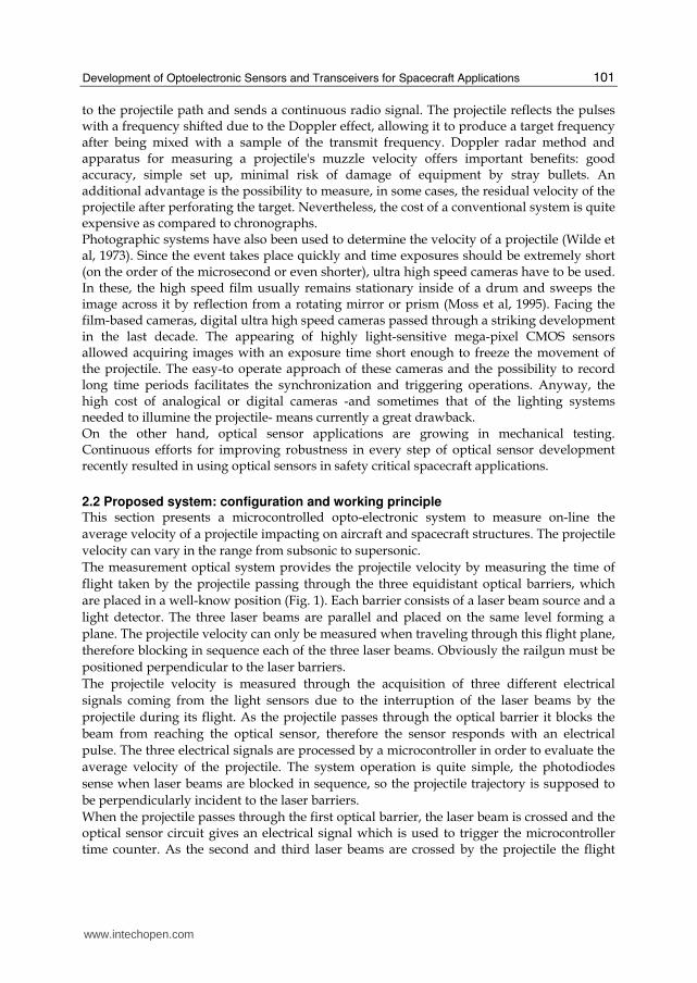
Fig. 2. System schematic showing the optical barriers, the projectile and the test structure.
The average velocity v of a projectile based on its time of flight between the optical barriers is given by the following equation:
1 2 3
1 2
3
S S Sv
T T T
⎛ ⎞= + +⎜ ⎟⎜ ⎟⎝ ⎠ (1)
where S is the distance between laser barriers that are equidistant, T1 is the flight time for the projectile between the first and second optical barriers, T2 is between the second and third barriers, and finally, T3 is the flight time between first and third barriers. Theoretically, T3 must be the sum of T1 plus T2, but it could be different because the system is counting
www.intechopen.com
Development of Optoelectronic Sensors and Transceivers for Spacecraft Applications
103
microcontroller clock periods. Therefore, projectile velocity is calculated as an average, using three distances between barriers and three flight times. This simple system operation is a robust technique to avoid potential failures of either the laser sources or the photodetectors. It is important to consider that during the flight the projectile velocity is not constant; it suffers a deceleration due to aerodynamic drag. It could be mathematically estimated by the following expression
( ) 21
2ρ= −p P D a
dvm A C v v
dt (2)
where v is the velocity of the projectile, mp is its mass, Ap is its cross-sectional area, CD is the drag coefficient, and ρa is the density of the air. This equation can be modified to represent the velocity variation with the distance, after a straightforward calculation the equation leads to
( )β = −dvdx
v v (3)
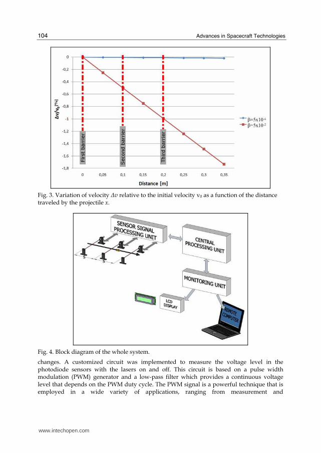
where β is a function of the velocity. Typical values of β vary from 5·10−4 to 5·10−2 in ballistic applications, considering low-density (polymers) or high-density (tungsten, uranium) projectiles; different shapes (blunt, spherical, conical, or ogival noses), cross-sectional areas; and velocities at subsonic, transonic, or fully supersonic ranges. Assuming a small variation of velocity when the projectile passes through the system, that must be confirmed afterward, we can consider CD and β as constant. The variation of velocity Δv relative to the initial velocity v0 as a function of the distance traveled by the projectile x could then be determined by direct integration of Eq. (3):
( )0
1βΔ = − −expv
xv
(4)
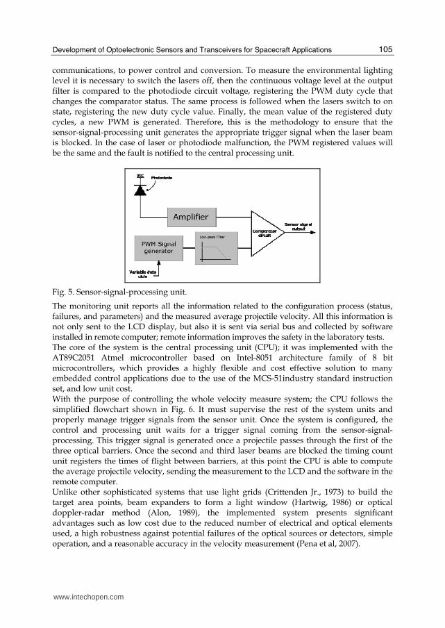
Fig. 3 shows the velocity variation between the three laser barriers of the system, it has been plotted using the Eq. (4). As can be observed the variation is less than 1% in the worst situation: projectile of small density, small radius, and high aerodynamic drag. The designed system comprises different functional blocks: electro-optical part, a sensor-signal-processing unit, a timing count block, a central processing unit and a monitoring unit with a LCD and a serial port (Fig. 4). The three laser barriers are part of the electro-optical block; they include three red laser diodes, with low output power, pointing to high-speed silicon photodiodes. This block also includes additional hardware to verify and to notify to the central processing unit of the optical barriers status; in case of malfunction the microcontroller is able to run all the necessary actions keeping the system operative. As can be shown in Fig. 5, the circuit integrating the sensor processing unit generates the trigger signal necessary to activate the timing count block. This unit also includes specific circuits which allow the system operation under different environmental lighting. The system evaluates the environmental lighting and sets the appropriate comparator voltage level in the sensor circuit and compares it to photodiode sensor voltage; as a result, when a projectile passes through the optical barrier and blocks the laser beam the comparator level
www.intechopen.com
Advances in Spacecraft Technologies
104
Fig. 3. Variation of velocity Δv relative to the initial velocity v0 as a function of the distance traveled by the projectile x.
Fig. 4. Block diagram of the whole system.
changes. A customized circuit was implemented to measure the voltage level in the photodiode sensors with the lasers on and off. This circuit is based on a pulse width modulation (PWM) generator and a low-pass filter which provides a continuous voltage level that depends on the PWM duty cycle. The PWM signal is a powerful technique that is employed in a wide variety of applications, ranging from measurement and
www.intechopen.com
Development of Optoelectronic Sensors and Transceivers for Spacecraft Applications
105
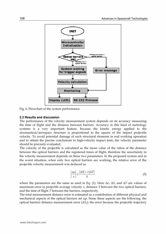
communications, to power control and conversion. To measure the environmental lighting level it is necessary to switch the lasers off, then the continuous voltage level at the output filter is compared to the photodiode circuit voltage, registering the PWM duty cycle that changes the comparator status. The same process is followed when the lasers switch to on state, registering the new duty cycle value. Finally, the mean value of the registered duty cycles, a new PWM is generated. Therefore, this is the methodology to ensure that the sensor-signal-processing unit generates the appropriate trigger signal when the laser beam is blocked. In the case of laser or photodiode malfunction, the PWM registered values will be the same and the fault is notified to the central processing unit.
Fig. 5. Sensor-signal-processing unit.
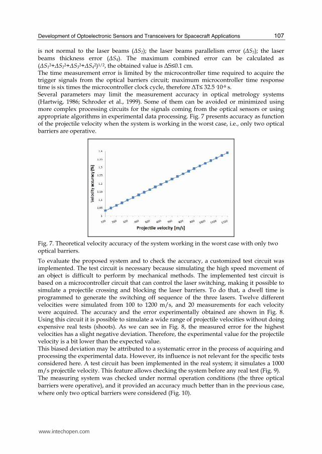
The monitoring unit reports all the information related to the configuration process (status, failures, and parameters) and the measured average projectile velocity. All this information is not only sent to the LCD display, but also it is sent via serial bus and collected by software installed in remote computer; remote information improves the safety in the laboratory tests. The core of the system is the central processing unit (CPU); it was implemented with the AT89C2051 Atmel microcontroller based on Intel-8051 architecture family of 8 bit microcontrollers, which provides a highly flexible and cost effective solution to many embedded control applications due to the use of the MCS-51industry standard instruction set, and low unit cost. With the purpose of controlling the whole velocity measure system; the CPU follows the simplified flowchart shown in Fig. 6. It must supervise the rest of the system units and properly manage trigger signals from the sensor unit. Once the system is configured, the control and processing unit waits for a trigger signal coming from the sensor-signal-processing. This trigger signal is generated once a projectile passes through the first of the three optical barriers. Once the second and third laser beams are blocked the timing count unit registers the times of flight between barriers, at this point the CPU is able to compute the average projectile velocity, sending the measurement to the LCD and the software in the remote computer. Unlike other sophisticated systems that use light grids (Crittenden Jr., 1973) to build the target area points, beam expanders to form a light window (Hartwig, 1986) or optical doppler-radar method (Alon, 1989), the implemented system presents significant advantages such as low cost due to the reduced number of electrical and optical elements used, a high robustness against potential failures of the optical sources or detectors, simple operation, and a reasonable accuracy in the velocity measurement (Pena et al, 2007).
www.intechopen.com
Advances in Spacecraft Technologies
106
Fig. 6. Flowchart of the system performance.
2.3 Results and discussion The performance of the velocity measurement system depends on its accuracy measuring the time of flight and the distance between barriers. Accuracy in this kind of metrology systems is a very important feature, because the kinetic energy applied to the aeronautical/aerospace structure is proportional to the square of the impact projectile velocity. To avoid potential damage of such structural elements in real working operation and to obtain the precise conclusions in high-velocity impact tests, the velocity parameter should be precisely evaluated. The velocity of the projectile is calculated as the mean value of the ratios of the distance
between the optical barriers and the registered times of flight, therefore the uncertainty in
the velocity measurement depends on these two parameters. In the proposed system and in
the worst situation, when only two optical barriers are working, the relative error of the
projectile velocity measurement was deduced as
Δ + ΔΔ ≤ S v Tv
v S (5)
where the parameters are the same as used in Eq. (1). Here Δv, ΔS, and ΔT are values of maximum error in projectile average velocity v, distance S between the two optical barriers, and the time of flight T between the barriers, respectively. The total measurement distance error is estimated as a contribution of different physical and mechanical aspects of the optical barriers set up. Some these aspects are the following: the optical barriers distance measurement error (ΔS1); the error because the projectile trajectory
www.intechopen.com
Development of Optoelectronic Sensors and Transceivers for Spacecraft Applications
107
is not normal to the laser beams (ΔS2); the laser beams parallelism error (ΔS3); the laser beams thickness error (ΔS4). The maximum combined error can be calculated as (ΔS12+ΔS22+ΔS32+ΔS42)1/2, the obtained value is ΔS≤0.1 cm. The time measurement error is limited by the microcontroller time required to acquire the trigger signals from the optical barriers circuit; maximum microcontroller time response time is six times the microcontroller clock cycle, therefore ΔT≤ 32.5·10-8 s. Several parameters may limit the measurement accuracy in optical metrology systems (Hartwig, 1986; Schroder et al., 1999). Some of them can be avoided or minimized using more complex processing circuits for the signals coming from the optical sensors or using appropriate algorithms in experimental data processing. Fig. 7 presents accuracy as function of the projectile velocity when the system is working in the worst case, i.e., only two optical barriers are operative.
Fig. 7. Theoretical velocity accuracy of the system working in the worst case with only two optical barriers.
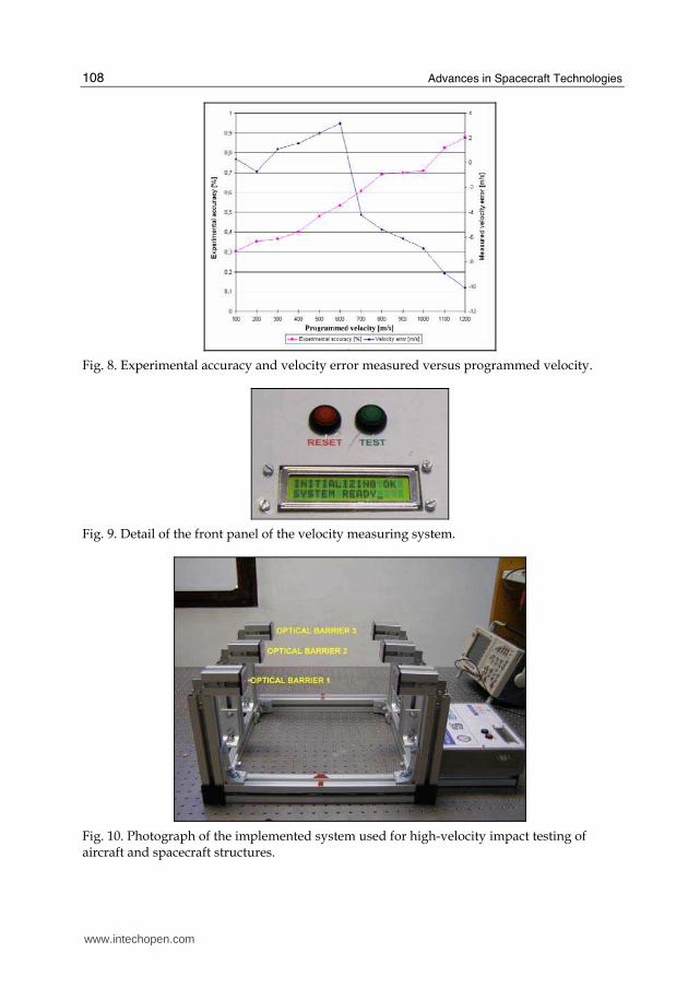
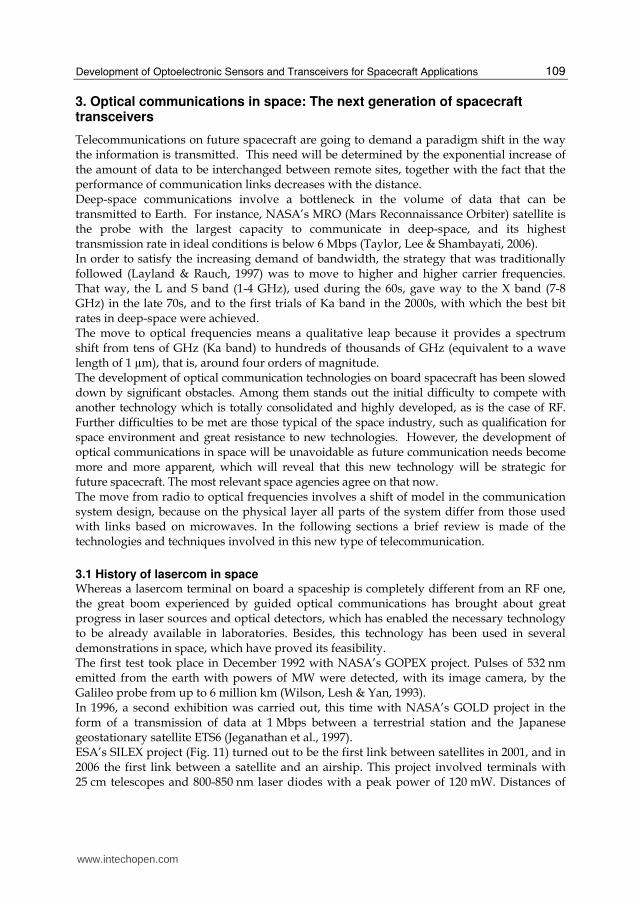
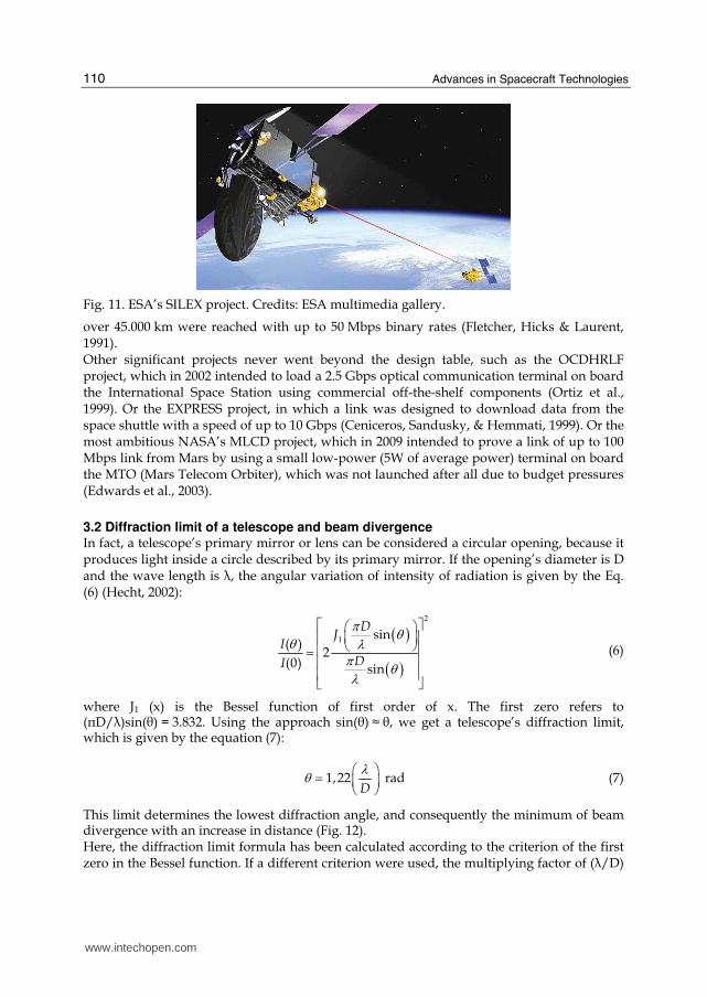
To evaluate the proposed system and to check the accuracy, a customized test circuit was implemented. The test circuit is necessary because simulating the high speed movement of an object is difficult to perform by mechanical methods. The implemented test circuit is based on a microcontroller circuit that can control the laser switching, making it possible to simulate a projectile crossing and blocking the laser barriers. To do that, a dwell time is programmed to generate the switching off sequence of the three lasers. Twelve different velocities were simulated from 100 to 1200 m/s, and 20 measurements for each velocity were acquired. The accuracy and the error experimentally obtained are shown in Fig. 8. Using this circuit it is possible to simulate a wide range of projectile velocities without doing expensive real tests (shoots). As we can see in Fig. 8, the measured error for the highest velocities has a slight negative deviation. Therefore, the experimental value for the projectile velocity is a bit lower than the expected value. This biased deviation may be attributed to a systematic error in the process of acquiring and processing the experimental data. However, its influence is not relevant for the specific tests considered here. A test circuit has been implemented in the real system; it simulates a 1000 m/s projectile velocity. This feature allows checking the system before any real test (Fig. 9). The measuring system was checked under normal operation conditions (the three optical barriers were operative), and it provided an accuracy much better than in the previous case, where only two optical barriers were considered (Fig. 10).
www.intechopen.com
Advances in Spacecraft Technologies
108
Fig. 8. Experimental accuracy and velocity error measured versus programmed velocity.
Fig. 9. Detail of the front panel of the velocity measuring system.
Fig. 10. Photograph of the implemented system used for high-velocity impact testing of aircraft and spacecraft structures.
www.intechopen.com
Development of Optoelectronic Sensors and Transceivers for Spacecraft Applications
109
3. Optical communications in space: The next generation of spacecraft transceivers
Telecommunications on future spacecraft are going to demand a paradigm shift in the way the information is transmitted. This need will be determined by the exponential increase of the amount of data to be interchanged between remote sites, together with the fact that the performance of communication links decreases with the distance. Deep-space communications involve a bottleneck in the volume of data that can be transmitted to Earth. For instance, NASA’s MRO (Mars Reconnaissance Orbiter) satellite is the probe with the largest capacity to communicate in deep-space, and its highest transmission rate in ideal conditions is below 6 Mbps (Taylor, Lee & Shambayati, 2006). In order to satisfy the increasing demand of bandwidth, the strategy that was traditionally followed (Layland & Rauch, 1997) was to move to higher and higher carrier frequencies. That way, the L and S band (1-4 GHz), used during the 60s, gave way to the X band (7-8 GHz) in the late 70s, and to the first trials of Ka band in the 2000s, with which the best bit rates in deep-space were achieved. The move to optical frequencies means a qualitative leap because it provides a spectrum shift from tens of GHz (Ka band) to hundreds of thousands of GHz (equivalent to a wave length of 1 µm), that is, around four orders of magnitude. The development of optical communication technologies on board spacecraft has been slowed down by significant obstacles. Among them stands out the initial difficulty to compete with another technology which is totally consolidated and highly developed, as is the case of RF. Further difficulties to be met are those typical of the space industry, such as qualification for space environment and great resistance to new technologies. However, the development of optical communications in space will be unavoidable as future communication needs become more and more apparent, which will reveal that this new technology will be strategic for future spacecraft. The most relevant space agencies agree on that now. The move from radio to optical frequencies involves a shift of model in the communication system design, because on the physical layer all parts of the system differ from those used with links based on microwaves. In the following sections a brief review is made of the technologies and techniques involved in this new type of telecommunication.
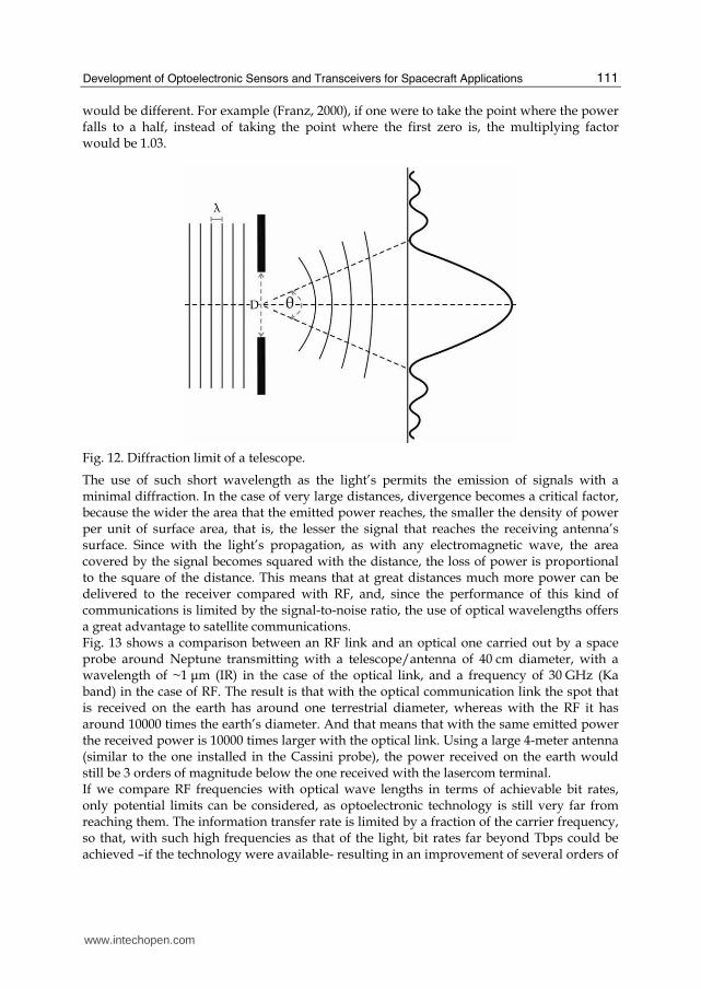
3.1 History of lasercom in space Whereas a lasercom terminal on board a spaceship is completely different from an RF one, the great boom experienced by guided optical communications has brought about great progress in laser sources and optical detectors, which has enabled the necessary technology to be already available in laboratories. Besides, this technology has been used in several demonstrations in space, which have proved its feasibility. The first test took place in December 1992 with NASA’s GOPEX project. Pulses of 532 nm emitted from the earth with powers of MW were detected, with its image camera, by the Galileo probe from up to 6 million km (Wilson, Lesh & Yan, 1993). In 1996, a second exhibition was carried out, this time with NASA’s GOLD project in the form of a transmission of data at 1 Mbps between a terrestrial station and the Japanese geostationary satellite ETS6 (Jeganathan et al., 1997). ESA’s SILEX project (Fig. 11) turned out to be the first link between satellites in 2001, and in 2006 the first link between a satellite and an airship. This project involved terminals with 25 cm telescopes and 800-850 nm laser diodes with a peak power of 120 mW. Distances of
www.intechopen.com
Advances in Spacecraft Technologies
110
Fig. 11. ESA’s SILEX project. Credits: ESA multimedia gallery.
over 45.000 km were reached with up to 50 Mbps binary rates (Fletcher, Hicks & Laurent, 1991). Other significant projects never went beyond the design table, such as the OCDHRLF project, which in 2002 intended to load a 2.5 Gbps optical communication terminal on board the International Space Station using commercial off-the-shelf components (Ortiz et al., 1999). Or the EXPRESS project, in which a link was designed to download data from the space shuttle with a speed of up to 10 Gbps (Ceniceros, Sandusky, & Hemmati, 1999). Or the most ambitious NASA’s MLCD project, which in 2009 intended to prove a link of up to 100 Mbps link from Mars by using a small low-power (5W of average power) terminal on board the MTO (Mars Telecom Orbiter), which was not launched after all due to budget pressures (Edwards et al., 2003).
3.2 Diffraction limit of a telescope and beam divergence In fact, a telescope’s primary mirror or lens can be considered a circular opening, because it produces light inside a circle described by its primary mirror. If the opening’s diameter is D and the wave length is ┣, the angular variation of intensity of radiation is given by the Eq. (6) (Hecht, 2002):
( )( )
2
1 sin( )
2(0) sin
DJ
IDI
π θθ λπ θλ
⎡ ⎤⎛ ⎞⎢ ⎥⎜ ⎟⎝ ⎠⎢ ⎥= ⎢ ⎥⎢ ⎥⎣ ⎦ (6)
where J1 (x) is the Bessel function of first order of x. The first zero refers to (πD/┣)sin(┠) = 3.832. Using the approach sin(┠) ≈ ┠, we get a telescope’s diffraction limit, which is given by the equation (7):
1,22Dλθ ⎛ ⎞= ⎜ ⎟⎝ ⎠ rad (7)
This limit determines the lowest diffraction angle, and consequently the minimum of beam divergence with an increase in distance (Fig. 12). Here, the diffraction limit formula has been calculated according to the criterion of the first zero in the Bessel function. If a different criterion were used, the multiplying factor of (┣/D)
www.intechopen.com
Development of Optoelectronic Sensors and Transceivers for Spacecraft Applications
111
would be different. For example (Franz, 2000), if one were to take the point where the power falls to a half, instead of taking the point where the first zero is, the multiplying factor would be 1.03.
Fig. 12. Diffraction limit of a telescope.
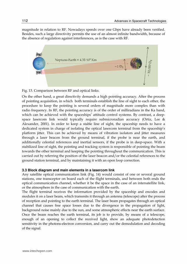
The use of such short wavelength as the light’s permits the emission of signals with a minimal diffraction. In the case of very large distances, divergence becomes a critical factor, because the wider the area that the emitted power reaches, the smaller the density of power per unit of surface area, that is, the lesser the signal that reaches the receiving antenna’s surface. Since with the light’s propagation, as with any electromagnetic wave, the area covered by the signal becomes squared with the distance, the loss of power is proportional to the square of the distance. This means that at great distances much more power can be delivered to the receiver compared with RF, and, since the performance of this kind of communications is limited by the signal-to-noise ratio, the use of optical wavelengths offers a great advantage to satellite communications. Fig. 13 shows a comparison between an RF link and an optical one carried out by a space probe around Neptune transmitting with a telescope/antenna of 40 cm diameter, with a wavelength of ~1 ┤m (IR) in the case of the optical link, and a frequency of 30 GHz (Ka band) in the case of RF. The result is that with the optical communication link the spot that is received on the earth has around one terrestrial diameter, whereas with the RF it has around 10000 times the earth’s diameter. And that means that with the same emitted power the received power is 10000 times larger with the optical link. Using a large 4-meter antenna (similar to the one installed in the Cassini probe), the power received on the earth would still be 3 orders of magnitude below the one received with the lasercom terminal. If we compare RF frequencies with optical wave lengths in terms of achievable bit rates, only potential limits can be considered, as optoelectronic technology is still very far from reaching them. The information transfer rate is limited by a fraction of the carrier frequency, so that, with such high frequencies as that of the light, bit rates far beyond Tbps could be achieved –if the technology were available- resulting in an improvement of several orders of
www.intechopen.com
Advances in Spacecraft Technologies
112
magnitude in relation to RF. Nowadays speeds over one Gbps have already been verified. Besides, such a large directivity permits the use of an almost infinite bandwidth, because of the absence of regulation against interferences, as is the case with RF.
Fig. 13. Comparison between RF and optical links.
On the other hand, a great directivity demands a high pointing accuracy. After the process
of pointing acquisition, in which both terminals establish the line of sight to each other, the
procedure to keep the pointing is several orders of magnitude more complex than with
radio frequency. In RF, the pointing accuracy is of the order of milliradians in the Ka band,
which can be achieved with the spaceships’ attitude control systems. By contrast, a deep-
space lasercom link would typically require submicroradian accuracy (Ortiz, Lee &
Alexander, 2001). In order to keep a stable line of sight, the spaceship needs to have a
dedicated system in charge of isolating the optical lasercom terminal from the spaceship’s
platform jitter. This can be achieved by means of vibration isolators and jitter measures
through a laser beacon from the ground terminal, if the probe is near the earth, and
additionally celestial references and inertial sensors, if the probe is in deep-space. With a
stabilized line of sight, the pointing and tracking system is responsible of pointing the beam
towards the other terminal and keeping the pointing throughout the communication. This is
carried out by referring the position of the laser beacon and/or the celestial references to the
ground station terminal, and by maintaining it with an open loop correction.
3.3 Block diagram and main elements in a lasercom link Any satellite optical communication link (Fig. 14) would consist of one or several ground stations, one transceptor on board each of the flight terminals, and between both ends the optical communication channel, whether it be the space in the case of an intersatellite link, or the atmosphere in the case of communication with the earth. The flight terminal receives the information provided by the spaceship and encodes and
modules it on a laser beam, which transmits it through an antenna (telescope) after the process
of reception and pointing to the earth terminal. The laser beam propagates through an optical
channel that causes free space losses due to the divergence in the propagation of light,
background noise mainly due to the sun, and some atmospheric effects near the earth surface.
Once the beam reaches the earth terminal, its job is to provide, by means of a telescope,
enough of an opening to collect the received light, show an adequate photodetection
sensitivity in the photons-electron conversion, and carry out the demodulation and decoding
of the signal.
www.intechopen.com
Development of Optoelectronic Sensors and Transceivers for Spacecraft Applications
113
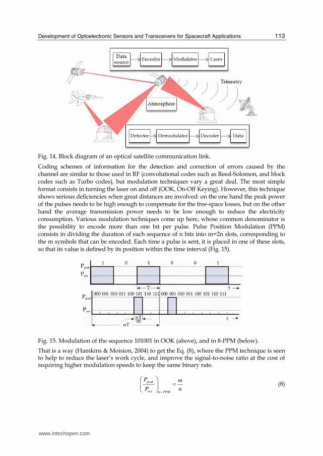
Fig. 14. Block diagram of an optical satellite communication link.
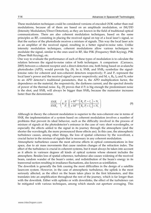
Coding schemes of information for the detection and correction of errors caused by the channel are similar to those used in RF (convolutional codes such as Reed-Solomon, and block codes such as Turbo codes), but modulation techniques vary a great deal. The most simple format consists in turning the laser on and off (OOK, On-Off Keying). However, this technique shows serious deficiencies when great distances are involved: on the one hand the peak power of the pulses needs to be high enough to compensate for the free-space losses, but on the other hand the average transmission power needs to be low enough to reduce the electricity consumption. Various modulation techniques come up here, whose common denominator is the possibility to encode more than one bit per pulse. Pulse Position Modulation (PPM) consists in dividing the duration of each sequence of n bits into m=2n slots, corresponding to the m symbols that can be encoded. Each time a pulse is sent, it is placed in one of these slots, so that its value is defined by its position within the time interval (Fig. 15).
Fig. 15. Modulation of the sequence 101001 in OOK (above), and in 8-PPM (below).
That is a way (Hamkins & Moision, 2004) to get the Eq. (8), where the PPM technique is seen to help to reduce the laser’s work cycle, and improve the signal-to-noise ratio at the cost of requiring higher modulation speeds to keep the same binary rate.
peak
ave m PPM
P m
P n−
⎛ ⎞ =⎜ ⎟⎝ ⎠ (8)
www.intechopen.com
Advances in Spacecraft Technologies
114
These modulation techniques could be considered versions of encoded OOK rather than real modulations, because all of them are based on an amplitude modulation, or IM/DD (Intensity Modulation/Direct Detection), as they are known in the field of traditional optical communications. There are also coherent modulation techniques, based on the same principles as RF, consisting in placing the received signal on top of a local laser’s signal, so that the surface of the photodiode receives a mixture of signals. This way the local laser acts as an amplifier of the received signal, resulting in a better signal-to-noise ratio. Unlike intensity modulation techniques, coherent modulations allow various techniques to modulate the signal, similar to the ones used in RF, like FSK (Frequency Shift Keying), PSK (Phase Shift Keying), etc. One way to evaluate the performance of each of these types of modulation is to calculate the relation between the signal-to-noise ratios of both techniques. A comparison (Carrasco, 2005) between a coherent receptor and a direct-detection one, both being based on avalanche photodiodes (APD), would provide Eq. (9). In it, SNRc and SNRd symbolize the signal-tonoise ratio for coherent and non-coherent detectors respectively; Pl and Pr represent the local laser’s power and the received signal’s power respectively; and M, x, R0, Id and Nt refer to an APD detector’s traditional parameters, that is, the APD multiplication factor, the dependence on the material, the responsivity, the darkness current, and the spectral density of power of the thermal noise. Eq. (9) proves that if Pl is big enough the predominant noise is the shot, and SNRc will always be bigger than SNRd because the numerator increases faster than the denominator.
2
0
20
4x
r d tc lx
d r l d t
e M R P I NSNR PSNR P e M R P I N
++
⎛ ⎞+ +⎛ ⎞ ⎡ ⎤⎣ ⎦= ⎜ ⎟⎜ ⎟⎜ ⎟ ⎜ ⎟+ +⎡ ⎤⎝ ⎠ ⎣ ⎦⎝ ⎠ (9)
Although in theory the coherent modulation is superior to the non-coherent one in terms of SNR, the implementation of a system based on coherent modulation involves a number of problems that prevent its ideal behavior, such as the difficulty involved in the process of mixture of signals at the photodetector’s entrance in the case of very short wavelengths, or especially the effects added to the signal in its journey through the atmosphere (and the shorter the wavelength, the more pronounced those effects are). In this case, the atmospheric turbulence causes, among other things, the loss of spatial coherence by the wavefront, a crucial factor in the mixture of signals that is necessary in any coherent modulation. Atmospheric turburlence causes the most adverse effects in optical communications in free space, due to air mass movements that cause random changes of the refraction index. The effect of the turbulence is crucial in coherent systems, but it must always be taken into account as it affects in variouos degrees all kinds of optical systems whose element includes the atmosphere. Besides loss of spatial coherence, turbulence also causes widening of the received beam, random wander of the beam’s center, and redistribution of the beam’s energy in its transversal section resulting in irradiance fluctuations, also known as scintillation. The downlink is generally the link causing the most difficulties in the design of a satellite lasercom system. However, in the case of atmospheric turbulence, the uplink is the most seriously affected, as the effect on the beam takes place in the first kilometers, and this translates into an amplification throughout the rest of the journey, which is far longer than with the downlink. Either with uplinks or with downlinks, the effect of the turbulence can be mitigated with various techniques, among which stands out aperture averaging. This
www.intechopen.com
Development of Optoelectronic Sensors and Transceivers for Spacecraft Applications
115
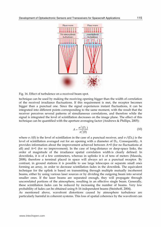
Fig. 16. Effect of turbulence on a received beam spot.
technique can be used by making the receiving opening bigger than the width of correlation of the received irradiance fluctuations. If this requirement is met, the receptor becomes bigger than a punctual one. Since the signal experiences instant fluctuations, it can be integrated into different points corresponding to the same moment, with the result that the receiver perceives several patterns of simultaneous correlations, and therefore while the signal is integrated the level of scintillation decreases on the image plane. The effect of this technique can be quantified with the aperture averaging factor (Andrews & Phillips, 2005):
2
2
( )
(0)I G
I
DA
σσ= (10)
where σ I2(0) is the level of scintillation in the case of a punctual receiver, and σ I2(DG) is the level of scintillation averaged out for an opening with a diameter of DG. Consequently, A provides information about the improvement achieved between A=0 (for no fluctuations at all) and A=1 (for no improvement). In the case of long-distance or deep-space links, the order of magnitude of the irradiance spatial correlation width is clearly defined: In downlinks, it is of a few centimeters, whereas in uplinks it is of tens of meters (Maseda, 2008); therefore a terminal placed in space will always act as a punctual receptor. By contrast, in ground stations it is possible to use large telescopes or separate small ones forming an array, in order to decrease scintillation fades in the downlink. The equivalent technique for the uplink is based on transmitting through multiple mutually incoherent beams, either by using various laser sources or by dividing the outgoing beam into several smaller ones. If the laser beams are separated enough, they will propagate through uncorrelated portions of the atmosphere, resulting in an effective single beam. Generally, these scintillation fades can be reduced by increasing the number of beams. Very low probability of fades can be obtained using 8–16 independent beams (Steinhoff, 2004). As mentioned above, wavefront distortions caused by atmosphere turbulence are particularly harmful in coherent systems. This loss of spatial coherence by the wavefront can
www.intechopen.com
Advances in Spacecraft Technologies
116
be mitigated with adaptive optics (AO). This kind of systems, otherwise quite often used in astronomical telescopes, provides real-time wavefront control, which allows the correction of distortions caused by turbulence on a millisecond time scale. However, its application in communication systems is not direct, due to significant differences with its imaging use: in astronomical telescopes, losses in signal energy can be solved by observing longer, which is not feasible when receiving information continuously. Besides, astronomical telescopes are only used for night operation under weak turbulence. In communications, AO systems need to work in daytime too, which causes strong turbulence conditions. The classic design of an AO system is based on wavefront measurements that allow the reconstruction of distorted wavefronts and the use of the resulting information to correct the incoming beam by means of active optical elements, such as deformable mirrors based on micro-electromechanical systems (MEMS). Wavefront measurement techniques can prove difficult under strong turbulence and, to solve that, alternative designs (Weyrauch & Vorontsov, 2004) have been proposed, based on wavefront control by optimization of a performance quality metric, such as the signal strength, which is readily available in lasercom terminals. Besides turbulence, the atmosphere causes other detrimental effects in optical communication links, althouth they can be mitigated through various techniques. For example, atmospheric gases, according to their composition, absorb part of the electromagnetic radiation in ways that depend on their frequency. Although in some regions the atmosphere is for all purposes opaque, there are some windows of minimal absorption in the optical area of the spectrum, such as the visible zone, from about 350 nm to around 750 nm, and those zones centered around 0.85 ┤m, 1.06 ┤m, 1.22 ┤m, 1.6 ┤m, 2.2 ┤m and 3.7 ┤m (Seinfeld & Pandis, 1998). Taking the atmospheric absorption into account is crucial because it determines the choice of the link’s wavelength, although the effect of its losses in the link is negligible if the choice of wavelength is correct. Clouds cause other detrimental atmospheric effects and can even completely block a laser’s transmission if they temporarily obstruct the line of sight. The variability in their appearance and their seeming fortuitousness allow the use of only two methods to avoid their presence during communications: a correct choice in placing the earth terminals, and their replication, so that at any given moment at least one site be free of clouds, for which locations are to be chosen that show no correlation in atmospheric variability. The most adequate positionings usually coincide with those of astronomical observatories, which are placed at altitudes, normally above 2000 m, so as to prevent the effects of the first layer of the atmosphere. An availability of over 90% is possible if at least three redundant sites are used (Link, Craddock & Allis, 2005). The first of the techniques mentioned above is also used to mitigate the scattering effect. Scattering is another of the effects that affect any optical signal propagating through the atmosphere. It is due to the presence of particles with different sizes and refraction indexes, which cause various types of light spread according to the relation between the particle size and the wavelength, and the relation between the particle’s refraction index and the medium’s. The most harmful effect caused by scattering over optical communications, particularly in
direct-detection systems, is not on the laser signal, but on the sun light during daytime and,
to a lesser degree, on the moon’s and planets’ light, if they come within the telescope’s field
of view. Solar photons are scattered by the atmospheric aerosols in all directions so that they
can propagate following the line of sight, causing a background noise that is received
together with the communication signal in the receiver, even if this is angularly far from the
sun. The noise power NS collected due to sky radiance is given by Eq. (11) (Hemmati, 2006).
www.intechopen.com
Development of Optoelectronic Sensors and Transceivers for Spacecraft Applications
117
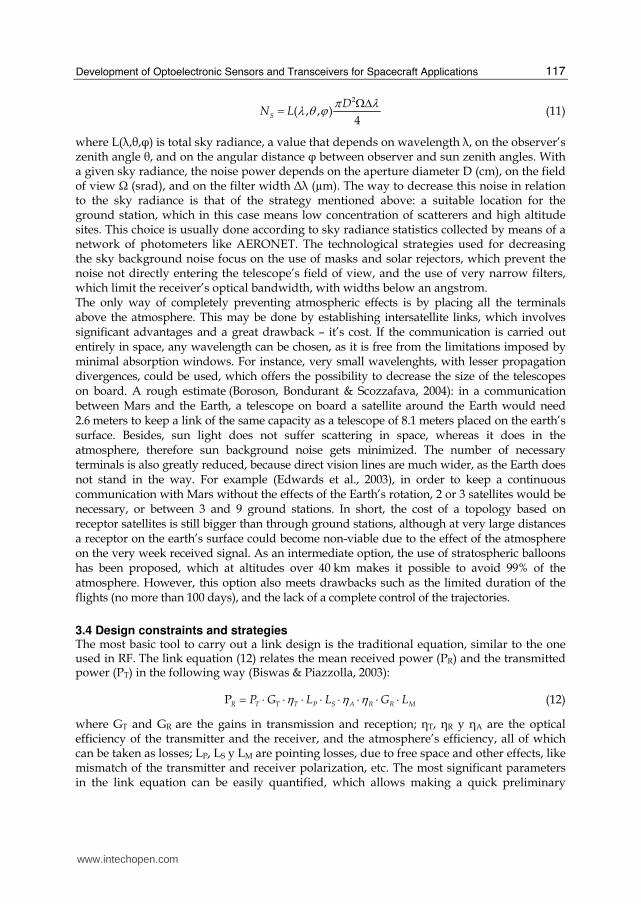
2
( , , )4
S
DN L
π λλ θ ϕ ΩΔ= (11)
where L(┣,┠,φ) is total sky radiance, a value that depends on wavelength ┣, on the observer’s zenith angle ┠, and on the angular distance φ between observer and sun zenith angles. With a given sky radiance, the noise power depends on the aperture diameter D (cm), on the field of view Ω (srad), and on the filter width Δ┣ (µm). The way to decrease this noise in relation to the sky radiance is that of the strategy mentioned above: a suitable location for the ground station, which in this case means low concentration of scatterers and high altitude sites. This choice is usually done according to sky radiance statistics collected by means of a network of photometers like AERONET. The technological strategies used for decreasing the sky background noise focus on the use of masks and solar rejectors, which prevent the noise not directly entering the telescope’s field of view, and the use of very narrow filters, which limit the receiver’s optical bandwidth, with widths below an angstrom. The only way of completely preventing atmospheric effects is by placing all the terminals above the atmosphere. This may be done by establishing intersatellite links, which involves significant advantages and a great drawback – it’s cost. If the communication is carried out entirely in space, any wavelength can be chosen, as it is free from the limitations imposed by minimal absorption windows. For instance, very small wavelenghts, with lesser propagation divergences, could be used, which offers the possibility to decrease the size of the telescopes on board. A rough estimate (Boroson, Bondurant & Scozzafava, 2004): in a communication between Mars and the Earth, a telescope on board a satellite around the Earth would need 2.6 meters to keep a link of the same capacity as a telescope of 8.1 meters placed on the earth’s surface. Besides, sun light does not suffer scattering in space, whereas it does in the atmosphere, therefore sun background noise gets minimized. The number of necessary terminals is also greatly reduced, because direct vision lines are much wider, as the Earth does not stand in the way. For example (Edwards et al., 2003), in order to keep a continuous communication with Mars without the effects of the Earth’s rotation, 2 or 3 satellites would be necessary, or between 3 and 9 ground stations. In short, the cost of a topology based on receptor satellites is still bigger than through ground stations, although at very large distances a receptor on the earth’s surface could become non-viable due to the effect of the atmosphere on the very week received signal. As an intermediate option, the use of stratospheric balloons has been proposed, which at altitudes over 40 km makes it possible to avoid 99% of the atmosphere. However, this option also meets drawbacks such as the limited duration of the flights (no more than 100 days), and the lack of a complete control of the trajectories.
3.4 Design constraints and strategies The most basic tool to carry out a link design is the traditional equation, similar to the one used in RF. The link equation (12) relates the mean received power (PR) and the transmitted power (PT) in the following way (Biswas & Piazzolla, 2003):
PR T T T P S A R R MP G L L G Lη η η= ⋅ ⋅ ⋅ ⋅ ⋅ ⋅ ⋅ ⋅ (12)
where GT and GR are the gains in transmission and reception; ┟T, ┟R y ┟A are the optical efficiency of the transmitter and the receiver, and the atmosphere’s efficiency, all of which can be taken as losses; LP, LS y LM are pointing losses, due to free space and other effects, like mismatch of the transmitter and receiver polarization, etc. The most significant parameters in the link equation can be easily quantified, which allows making a quick preliminary
www.intechopen.com
Advances in Spacecraft Technologies
118
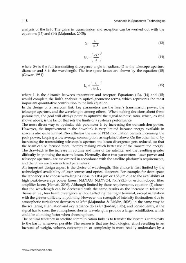
analysis of the link. The gains in transmission and reception can be worked out with the equations (13) and (14) (Majumdar, 2005):
2
16T
T
G = Θ (13)
2
R
DG
πλ
⎛ ⎞= ⎜ ⎟⎝ ⎠ (14)
where ΘT is the full transmitting divergence angle in radians, D is the telescope aperture diameter and ┣ is the wavelength. The free-space losses are shown by the equation (15) (Gowar, 1984):
2
4SL
Lλπ
⎛ ⎞= ⎜ ⎟⎝ ⎠ (15)
where L is the distance between transmitter and receptor. Equations (13), (14) and (15) would complete the link’s analysis in optical-geometric terms, which represents the most important quantitative contribution to the link equation. In the design of a lasercom link, key parameters are the laser’s transmission power, the telescope aperture, and the wavelength, among others. When making decisions about these parameters, the goal will always point to optimize the signal-to-noise ratio, which, as was shown above, is the factor that sets the limits of a system’s performance. The most direct way to optimize this parameter is by increasing the transmission power. However, the improvement in the downlink is very limited because energy available in space is also quite limited. Nevertheless the use of PPM modulation permits increasing the peak power, keeping a low average consumption, as explained above. On the other hand, by increasing the transmitting telescope’s aperture the beam divergence gets reduced, so that the beam can be focused more, thereby making much better use of the transmitted energy. The drawback is the increase in volume and mass of the satellite, and the resulting greater difficulty in pointing the narrow beam. Normally, these two parameters –laser power and telescope aperture– are maximized in accordance with the satellite platform’s requirements, and then they are taken as fixed parameters. An important design aspect is the choice of wavelength. This choice is first limited by the technological availability of laser sources and optical detectors. For example, for deep-space the tendency is to choose wavelengths close to 1.064 µm or 1.55 µm due to the availability of high peak-to-average power lasers: Nd:YAG, Nd:YVO4, Nd:YKLF or erbium-doped fiber amplifier lasers (Hemati, 2006). Although limited by these requirements, equation (2) shows that the wavelength can be decreased with the same results as the increase in telescope diameter, i.e., less beam divergence without affecting the flight terminal, except in relation with the greater difficulty in pointing. However, the strength of intensity fluctuations due to atmospheric turbulence decreases as ┣-7/6 (Majumdar & Ricklin, 2008), in the same way as the scattering attenuation and sky radiance do as ┣-4 (Jordan, 1985), and consequently, if the signal has to cross the atmosphere, shorter wavelengths provide a larger scintillation, which could be a limiting factor when choosing them. The natural tendency in satellite communication links is to transfer the system’s complexity to the Earth, whenever possible. The reason is that any technological effort resulting in an increase of weight, volume, consumption or complexity is more readily undertaken by a
www.intechopen.com
Development of Optoelectronic Sensors and Transceivers for Spacecraft Applications
119
ground station than by a satellite. Regarding this aspect, there is a number of techniques that make it possible to optimize the overall link performance, by making improvements in the ground station. The most direct ones are the increase of the receiver’s collecting area and the improvement in optoelectronic efficiency of the receptors. It is certainly possible to increase the gain in reception by building a very large telescope, although this method meets serious limitations due to the high costs and complexity of this kind of installations. Nowadays, astronomical telescopes with the largest aperture only reach 10 meters, in spite of very high costs of development and maintenance. To overcome this limitation in the ground station, a proposal has been made and tested (Vilnrotter et al., 2004) consisting of a synthesis of very large optical apertures by means of arrays of smaller telescopes. The difference between collecting light by using a large telescope and an array of smaller ones is that in the first case all the light is focused before its detection, either with one big element or an array of multiple smaller segments. By contrast, in an array of telescopes each element in the array focuses the received beam into different photodetectors, in order to later combine the signals in the electric domain. This idea offers the opportunity to rapidly implement cost-effective large apertures, otherwise unfeasible by using one single telescope that would require massive support structures, developing the necessary custom optics, complex alignment process, etc, being all of this exacerbated by the great gravitational requirements found in such heavy installations. Besides, there is a number of other significant advantages: reuse in future, more demanding missions, by making use of their great scalability through the addition of more telescopes to the array; very fast recovery in case of failure by just replacing one telescope with a spare one; the possibility of flexibly managing all the elements in the array for more than one simultaneous link; and lesser requirements over the telescopes, which makes it possible to use cheap off-the-shelf systems. Significant improvements in detector efficiency have also been carried out. With a detector based on direct detection, the most straightforward method is by using photodetectors with inner amplification, such as avalanche photodiodes (APD), or photomultiplier tubes (PMT). The receiver’s noise contribution can be ignored in some ways, such as by cooling the detector down to cryogenic temperatures; with high bias voltages, which leads to very high amplification gains; and by using error correction coding to mitigate the effect of false photon detections in the form of dark counts. This way it is possible to distinguish the entrance of a single photon, procedure called photon counting. There are two types of photon counters: linear and geiger-mode. The former can be implemented with an APD or a PMT, and provide an electrical signal that is proportional to the number of received photons. They are limited by the detector’s bandwidth, which gives the greatest temporary resolution to distinguish photons. Geiger-mode photon counters work in a way similar to a Geiger counter and are implemented by taking an APD’s bias voltage very close to saturation. The result is that a photon’s arrival triggers a carrier’s avalanche that provides a very intense pulse, which equates to an infinite gain. These devices are limited by the fact that, after each avalanche, some recovery time (in the order of µs) must go by so as to bring the APD back to below breakdown and make it ready for the next detection. During this time, the arrival of a new photon would be ignored. This can be overcome by means of a GM-APD array, so that there is an increased probability of some detector always being ready to trigger an avalanche. As in the case of arrays of telescopes, the use of arrays of detectors offer additional advantages: It is possible to use them to extract information for the tracking process, as well as information related to atmospheric conditions, because they can distinguish between pixels; and they offer a way to dynamically adapt the field of view, depending on the number of elements used. This
www.intechopen.com
Advances in Spacecraft Technologies
120
type of detection has proved to offer efficiency improvements of up to 40× in terms of photons per bit, compared with traditional systems (Mendenhall et al., 2007).
4. Conclusions
An optoelectronic velocity measurement system was designed, developed and implemented using discrete circuits. The system is able to measure the velocity of small projectiles, flying at speeds in the range from 30 to 1200 m/s. Velocity system is based on the noncontact measurement of the projectile times of flight between three optical barriers. The velocity data is computed by the control process unit (microcontroller) and the result is displayed on a LCD mounted in the system and sent to remote computer using a serial protocol. The velocity accuracy was theoretically calculated and experimentally evaluated. Values better than 1% were obtained for the worst case, when one of the optical barrier. This accuracy depends mainly on the projectile velocity and optical barrier distances, and it could be improved by increasing either the clock frequency of microcontroller or the distance between optical barriers. The influence of background light in the measured velocity is negligible. The implemented system is simple, cost-effective, and robust against potential failures of the optical elements and covers a wide velocity range from subsonic to supersonic. Regarding to communication systems, a review has been made of the fundamentals on which are based free-space lasercom transceivers on board spacecraft. As it was shown, this new technology offers improvements of several orders of magnitude over present RF links, and thus it seems to have a great potential in the future. However, the leap from microwave frequencies to optical wavelengths involves a paradigm shift in how the information is transmitted, which requires the development of a new technology at all levels of the communication link. The influence of the main elements that make up a lasercom link has been studied, focusing on the techniques that are most crucial to mitigate the specific problems arising from this type of communication: atmospheric effects affecting optical signals, difficulty in controlling the pointing and tracking, etc. Finally, an analysis of the main strategies to be followed in the design of a free-space laser communication system has been presented, so that all the key parameters involved in an optical link are revised.
5. References
Alon, Y. (1989). Doppler Radar Method and Apparatus for Measuring a Projectile's Muzzle Velocity, United States Patent 4837718, Lear Siegler, Inc. (Santa Monica, CA), United States.
Andrews, L. C. & Phillips, R. L. (2005). Laser Beam Propagation through Random Media, SPIE Press Monograph, Volume PM152, ISBN 0819459488, Bellingham, Washington, United States.
Biswas, A. & Piazzolla, S. (2003). Deep Space Optical Communications Downlink Budget from Mars: System Parameters. The Interplanetary Network Progress Report, 42-154, pp. 1-38, August, 2003.
Boroson, D. M.; Bondurant, R. S. & Scozzafava, J. J. (2004). Overview of High Rate Deep Space Laser Communications Options, Free-Space Laser Communications Technologies XVI, Proceedings of SPIE, Vol. 5338, pp. 37-49, January, 2004.
Carrasco, A. (2005). Diseño de un Enlace de Comunicaciones Ópticas con Marte. Engineering degree final project, University of Málaga.
Ceniceros, J.M.; Sandusky, J. V. & Hemmati, H. (1999). 10 Gbps Shuttle-to-Ground Adjunct Communication Link Capability Experiment, 1999 Shuttle Small Payloads Project Office Symposium, NASA/CP-1999-209476, pp. 293-295, September, 1999.
www.intechopen.com
Development of Optoelectronic Sensors and Transceivers for Spacecraft Applications
121
Chan, V.W.S. (2000). Optical Space Communications, Millennium Issue IEEE Journal on Selected Topics in Quantum Electronics, Vol. 6, No. 6, pp. 959–975, November-December, 2000.
Crittenden Jr., E.C.; King, R. A. & Andrews, T. C. (1973). Target Measurement System for Precise Projectile Location, United States Patent 3727069, Litton Systems Inc. (Beverly Hills, CA), United States.
Edwards, B. L.; Townes, S. A.; Bondurant, R. S.; Scozzafava, J. J.; Boroson, D. M.; Roberts, W. T.; Biswas, A.; Pillsbury, A. D.; Khatri, F. I.; Burnside, J. W.; Bold, D. R.; Murphy, D. V.; McIntosh, A. K.; Caplan, D. O.; DeCew, A. E.; Sharma, J; Parvin, B. A.; Fitzgerald, R. J.; Zingales, S. H. & De Paula, R. (2003). Overview of the Mars Laser Communications Demonstration Project, American Institute of Aeronautics and Astronautics AIAA Space 2003 Conference, Paper 2003-6417, pp. 1444-1454, September, 2003.
ESA multimedia gallery. http://www.esa.int/esa-mmg/mmghome.pl. Fletcher, G. D.; Hicks, T. R. & Laurent, B. (1991). The SILEX Optical Interorbit Link
Experiment. Electronics & Communication Engineering Journal, Volume. 3, No. 6, pp. 273-279, ISSN 09540695, December, 1991.
Franz, J. H. & Jain, V. K. (2000). Optical Communications, Components and Systems. Alpha Science Internacional Ltd, ISBN 1842650556, New Delhi, India.
Gowar, J. (1984). Optical Communication Systems. Prentice-Hall International Inc., ISBN 0136387276, London, United Kingdom.
Hamkins, J. & Moision, B. (2004). Selection of Modulation and Codes for Deep Space Optical Communications. Free-Space Laser Communication Technologies XVI, Proceedings of SPIE, Vol. 5338, pp. 123-130, January, 2004.
Hartwig, R. (1986). Accuracy of Velocity Measurement of Projectiles with Fins and Tracers by Means of Sky-Screens. Journal of Ballistics. Vol. 9, No. 3, pp. 2299-2310, 1986.
Hecht, E. (2002). Optics. Addison Wesley, ISBN 0321188780, San Francisco, United States. Hemmati, H. (2006). Deep Space Optical Communications. John Wiley & Sons, ISBN
0470040025, New Jersey, United States. Henniger, H.; Giggenbach, D; Florian, D. & Rapp, C. (2003). Evaluation of FEC for the
Atmospheric Optical IM/DD Channel, Free-Space Laser Communication Technologies XV, Proceedings of the SPIE, Vol. 4975, pp. 1-11, July, 2003.
Jeganathan, M.; Toyoshima, M.; Wilson, K.; James, J.; Xu, G. & Lesh, J. (1997). Data Analysis Results from the GOLD Experiments. Free-Space Laser Communications Technologies IX, Proceedings of SPIE, Vol. 2990, pp. 70-81, April, 1997.
Jordan, E. C. (1985). Reference Data for Engineers: Radio, Electronics, Computer & Communications. Howard W. Sams & Co., Inc., ISBN 0672215632, Indiana, United States.
Lambert, S. G. & Casey, W. L. (1995). Laser Communications in Space. Artech House, ISBN 0890067228, Boston, United States.
Layland, J. W & Rauch, L. L. (1997). The Evolution of Technology in the Deep Space Network: A History of the Advanced Systems Program. The Telecommunications and Data Acquisition Progress Report, TDA PR 42-130, pp. 1-44, August, 1997.
Link, R. P.; Craddock, M. E. & Allis, R. J. (2005). Mitigating the Impact of Clouds on Optical Communications, Aerospace Conference 2005 IEEE, pp. 1258-1265, ISBN 0780388704, March, 2005.
Majumdar, A. K. (2005). Free-space Laser Communication Performance in the Atmospheric Channel. Journal of Optical and Fiber Communications Research, Volume 2, No. 4, pp. 345-396, October, 2005.
Majumdar, A. K. & Ricklin, J. C. (2008). Free-Space Laser Communications, Principles and Advances. Springer, ISBN 9780387286525, New York, United States.
www.intechopen.com
Advances in Spacecraft Technologies
122
Maseda, R. H. (2008). Estudio de Enlaces de Comunicaciones Ópticas a Grandes Distancias en presencia de Turbulencia Atmosférica. Engineering degree final project, Carlos III University of Madrid.
Mendenhall, J. A.; Candell, L. M.; Hopman, P. I.; Zogbi, G.; Boroson, D. M.; Caplan, D. O.; Digenis, C. J.; Hearn, D. R. & Shoup, R. C. (2007). Design of an Optical Photon Counting Array Receiver System for Deep-Space Communications. Proceedings of the IEEE, Volume 95, No. 10, pp. 2059-2069, ISSN 00189219, October, 2007.
Moss, G.M.; Leeming, D.W. & Farrar, C.L. (1995). Military Ballistics: a basic manual, Brassey’s New Battlefield Weapons Systems and Technology Series, ISBN 1857530845, London, United Kingdom.
Ortiz, G. G.; Jeganathan, M.; Sandusky, J. V. & Hemmati, H. (1999). Design of a 2.5 Gbps Optical Transmitter for the International Space Station. Free-Space Laser Communication Technologies XI, Proceedings of SPIE, Vol. 3615, pp. 179-184, April, 1999.
Ortiz, G. G.; Lee, S. & Alexander, J. W. (2001). Sub-microradian Pointing for Deep Space Optical Telecommunications Network. 19th AIAA International Communications Satellite Systems Conference, 921, pp. 1-16, No. 921, April, 2001.
Paulter, Jr. N. G. & Larson, D. R. (2009). Reference Ballistic Chronograph, Optical Engineering, Vol. 48, No. 4, pp. 43602-43607, April, 2009.
Pena, J. M. S.; Marcos, C.; Fernández, M. Y. & Zaera, R.(2007). Cost-Effective Optoelectronic System to Measure the Projectile Velocity in High-Velocity Impact Testing of Aircraft and Spacecraft Structural Elements, Optical Engineering, Vol. 46, No. 5, pp. 510141-510146, ISSN 00913286, May, 2007.
Schroder K.A.; Allen R.J.; Parker J.V. & Snowden P.T. (1999). In-Bore Measurements Using an Optical Data Link, IEEE Transactions on Magnetics, Vol. 35, pp. 95-99, ISSN 00189464, January 1999.
Seinfeld, J. H. & Pandis, S. N. (1998). Atmospheric Chemistry and Physics: From Air Pollution to Climate Change. John Wiley & Sons Inc., ISBN 0471178160, New York, United States.
Steinhoff, N. (2004). Irradiance and Fade Characteristics for the JPL MLCD Program. The Optical Science Company, Report No. TR-1657, California.
Taylor, J.; Lee, D. K. & Shambayati, S. (2006). Mars Reconnaissance Orbiter Telecommunications. DESCANSO Design and Performance Summary Series, Article 12.
Vilnrotter, V.; Andrews, K.; Lau, C. & Srinivasan, M. (2004). Conceptual Design of an Optical Array Receiver, with Preliminary Experimental Results. The Interplanetary Network Progress Report, Volume 42-156, pp. 1-9, February, 2004.
Weyrauch, T & Vorontsov, M. A. (2004). Free-space Laser Communications with Adaptive Optics: Atmospheric Compensation Experiments. Journal of Optical and Fiber Communications Research, Volume 1, No. 4, pp. 355-379, ISBN 18673007, December, 2004.
Wilde, A. F.; Roylance, D. K. & Rogers, J. M. (1973). Photographic Investigation of High-Speed Missile Impact Upon Nylon Fabric, Part I: Energy Absorption and Cone Radial Velocity in Fabric, Textile Research Journal, Vol. 43, No. 12, pp. 753-761, December, 1973.
Wilson, K. E.; Lesh, J. R. & Yan, T. Y. (1993). GOPEX: A Laser Uplink to the Galileo Spacecraft on Its Way to Jupiter. Free-Space Laser Communication Technologies V, Proceedings of SPIE, Volume 1866, pp. 138-146, January, 1993.
Zukas, J. A.; Nicholas, T. & Swift, H. F. (1992). Impact Dynamics, Krieger Publishing Company, ISBN 0894646907, Florida, United States.
www.intechopen.com
Advances in Spacecraft TechnologiesEdited by Dr Jason Hall
ISBN 978-953-307-551-8Hard cover, 596 pagesPublisher InTechPublished online 14, February, 2011Published in print edition February, 2011
InTech EuropeUniversity Campus STeP Ri Slavka Krautzeka 83/A 51000 Rijeka, Croatia Phone: +385 (51) 770 447 Fax: +385 (51) 686 166www.intechopen.com
InTech ChinaUnit 405, Office Block, Hotel Equatorial Shanghai No.65, Yan An Road (West), Shanghai, 200040, China
Phone: +86-21-62489820 Fax: +86-21-62489821
The development and launch of the first artificial satellite Sputnik more than five decades ago propelled boththe scientific and engineering communities to new heights as they worked together to develop novel solutionsto the challenges of spacecraft system design. This symbiotic relationship has brought significant technologicaladvances that have enabled the design of systems that can withstand the rigors of space while providingvaluable space-based services. With its 26 chapters divided into three sections, this book brings togethercritical contributions from renowned international researchers to provide an outstanding survey of recentadvances in spacecraft technologies. The first section includes nine chapters that focus on innovativehardware technologies while the next section is comprised of seven chapters that center on cutting-edge stateestimation techniques. The final section contains eleven chapters that present a series of novel controlmethods for spacecraft orbit and attitude control.
How to referenceIn order to correctly reference this scholarly work, feel free to copy and paste the following:
José M. Sánchez-Pena, Carlos Marcos, Alberto Carrasco, Ricardo Vergaz and Ramón Zaera (2011).Development of Optoelectronic Sensors and Transceivers for Spacecraft Applications, Advances in SpacecraftTechnologies, Dr Jason Hall (Ed.), ISBN: 978-953-307-551-8, InTech, Available from:http://www.intechopen.com/books/advances-in-spacecraft-technologies/development-of-optoelectronic-sensors-and-transceivers-for-spacecraft-applications

© 2011 The Author(s). Licensee IntechOpen. This chapter is distributedunder the terms of the Creative Commons Attribution-NonCommercial-ShareAlike-3.0 License, which permits use, distribution and reproduction fornon-commercial purposes, provided the original is properly cited andderivative works building on this content are distributed under the samelicense.