Embed Size (px)
Citation preview
Page 1 A-291
OREGON OCCUPATIONAL SAFETY AND HEALTH DIVISION
DEPARTMENT OF CONSUMER AND BUSINESS SERVICES
PROGRAM DIRECTIVE
Program Directive A-291
Issued November 13, 2013
SUBJECT: Machine guarding: defining mechanical power presses and similarly
configured machinery.
AFFECTED CODES/
DIRECTIVES: Division 2/O, 1910.211 Definitions, 1910.212 General Requirements for all
Machines, 1910.217 Mechanical Power Presses, and STD 01-12.27
Applicable Standards As They Pertain to Iron Workers and Mechanical
Power Presses.
This directive replaces A-13, A-55, A-69, A-87, A-92 and A-172.
PURPOSE: To aid in the recognition and applicabil ity of 1910.212 and
1910.217 as they relate to mechanical power presses, platen presses, iron
workers, press brakes, and other similarly configured machinery.
To clarify point of operation guarding requirements for mechanical power
presses (including during diesetting operations).
BACKGROUND:
Over the years, employers have been confused regarding the applicability of
standards for mechanical power presses and pneumatic or hydraulic presses;
in addition to other similarly configured machinery such as press brakes,
platen presses, iron workers, shears, and riveting and notching machinery.
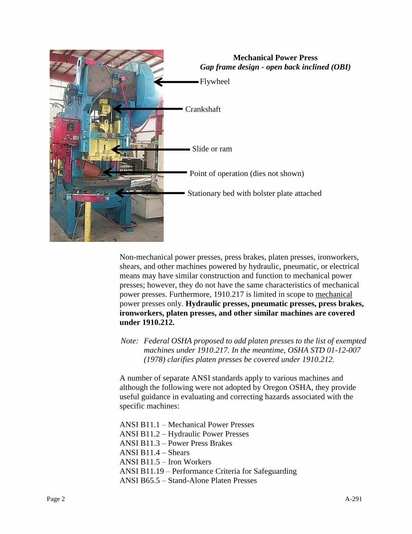
Division 2/O defines a “press” (for coverage under 1910.217) as a
“…mechanically powered machine that shears, punches, forms or assembles
metal or other material by means of cutting, shaping, or combination dies
attached to slides. A press consists of a stationary bed or anvil, and a slide (or
slides) having a controlled reciprocating motion toward and away from the
bed surface, the slide being guided in a definite path by the frame of the
press.”
Page 2 A-291
Non-mechanical power presses, press brakes, platen presses, ironworkers,
shears, and other machines powered by hydraulic, pneumatic, or electrical
means may have similar construction and function to mechanical power
presses; however, they do not have the same characteristics of mechanical
power presses. Furthermore, 1910.217 is limited in scope to mechanical
power presses only. Hydraulic presses, pneumatic presses, press brakes,
ironworkers, platen presses, and other similar machines are covered
under 1910.212.
Note: Federal OSHA proposed to add platen presses to the list of exempted
machines under 1910.217. In the meantime, OSHA STD 01-12-007
(1978) clarifies platen presses be covered under 1910.212.
A number of separate ANSI standards apply to various machines and
although the following were not adopted by Oregon OSHA, they provide
useful guidance in evaluating and correcting hazards associated with the
specific machines:
ANSI B11.1 – Mechanical Power Presses
ANSI B11.2 – Hydraulic Power Presses
ANSI B11.3 – Power Press Brakes
ANSI B11.4 – Shears
ANSI B11.5 – Iron Workers
ANSI B11.19 – Performance Criteria for Safeguarding
ANSI B65.5 – Stand-Alone Platen Presses
Mechanical Power Press
Gap frame design - open back inclined (OBI)
Flywheel
Crankshaft
Stationary bed with bolster plate attached
Slide or ram
Point of operation (dies not shown)
Page 3 A-291
MECHANICAL POWER PRESSES
BACKGROUND
On December 3, 1974, final federal amendments to 1910.217(b)(1) through
1910.217(h)(13)(ii) were published in the Federal Register. The statement
preceding the amendments noted that while the previous "no hands in die"
ruling eliminated an operator to ever have hands in the point of operation, it did
not result in hazard-free operation. The installation of redundant guards and
devices as backup safeties did not significantly improve safety either.
Moreover, questions of technological and economic infeasibility were raised.
While it is believed that "no hands in die" should continue to be an industry
goal, OSHA decided to revise the absolute "no hands in die" requirement in
favor of improving the use of a single means of press safeguarding.
1910.217(c)(5) was added in 1975 to address safeguarding when the
operator’s hand(s) is in the point of operation.
For most operations, adequate protection can be afforded by a single guard or
guarding device as long as the means of protection is properly designed,
installed, maintained, and, most importantly, used under supervision. From an
enforcement standpoint, employer adherence to each of these elements of a
press guarding program in the workplace takes on increased importance.
1910.217(b)(1) through 1910.217(h)(13)(ii) covers the protection of press
operators, die setters, and maintenance personnel engaged in mechanical power
press operations such as stroking, die tryout, die setting and maintenance. Press
machines which are not mechanical power presses such as forging presses,
press brakes, shears, ironworkers, powder metal presses, die presses, brick
presses, dinkers and clickers, engraving, and others are covered by other
sections of Division 2/O. Most mechanical power presses work on metal but
some are used on materials such as plastic, paper, and fiberboard.
Page 4 A-291
MECHANICAL POWER PRESS RECOGNITION
A. Mechanical Power Press
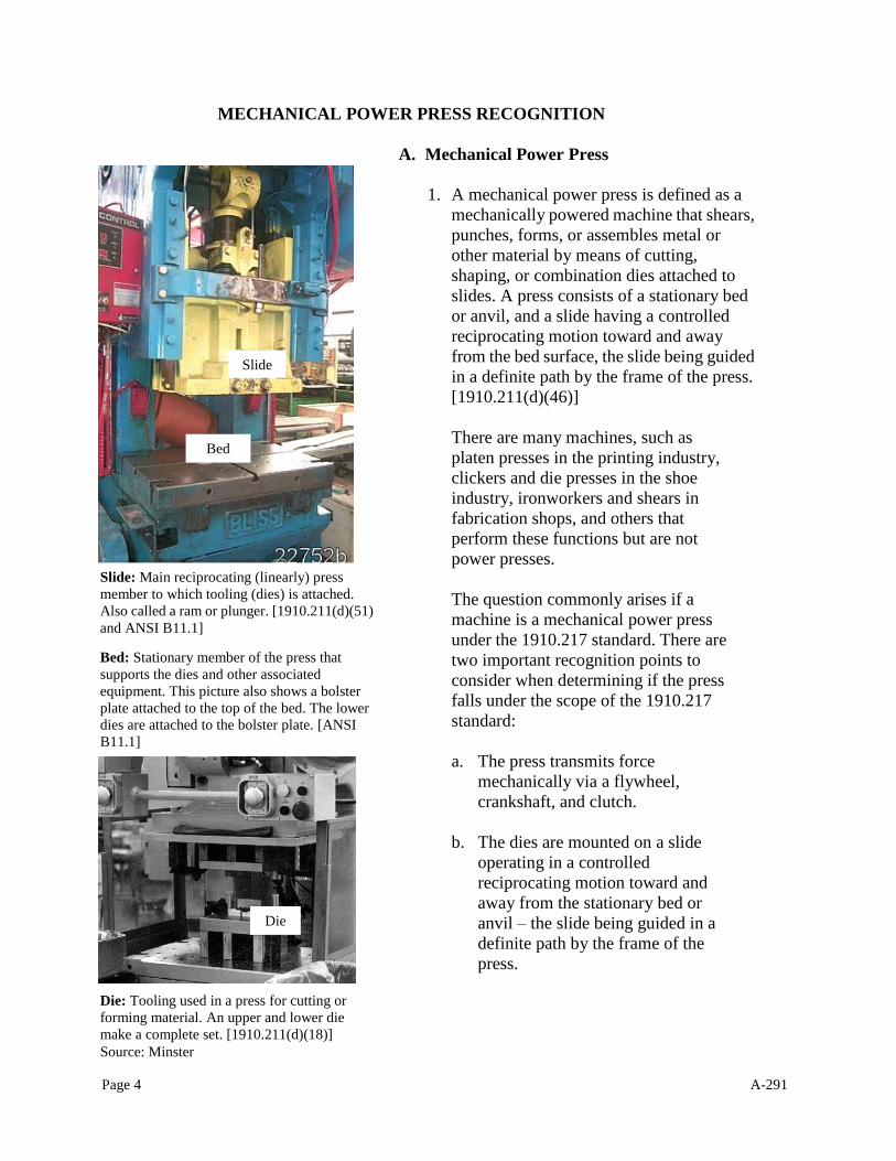
1. A mechanical power press is defined as a
mechanically powered machine that shears,
punches, forms, or assembles metal or
other material by means of cutting,
shaping, or combination dies attached to
slides. A press consists of a stationary bed
or anvil, and a slide having a controlled
reciprocating motion toward and away
from the bed surface, the slide being guided
in a definite path by the frame of the press.
[1910.211(d)(46)]
There are many machines, such as
platen presses in the printing industry,
clickers and die presses in the shoe
industry, ironworkers and shears in
fabrication shops, and others that
perform these functions but are not
power presses.
The question commonly arises if a
machine is a mechanical power press
under the 1910.217 standard. There are
two important recognition points to
consider when determining if the press
falls under the scope of the 1910.217
standard:
a. The press transmits force
mechanically via a flywheel,
crankshaft, and clutch.
b. The dies are mounted on a slide
operating in a controlled
reciprocating motion toward and
away from the stationary bed or
anvil – the slide being guided in a
definite path by the frame of the
press.
Slide
Bed
Slide: Main reciprocating (linearly) press
member to which tooling (dies) is attached.
Also called a ram or plunger. [1910.211(d)(51)
and ANSI B11.1]
Bed: Stationary member of the press that
supports the dies and other associated
equipment. This picture also shows a bolster
plate attached to the top of the bed. The lower
dies are attached to the bolster plate. [ANSI
B11.1]
Die: Tooling used in a press for cutting or
forming material. An upper and lower die
make a complete set. [1910.211(d)(18)]
Source: Minster
Slide
Bed
Die
Page 5 A-291
Mechanical power presses come in a variety of
designs. This press has the flywheel on the right
and the clutch is inside the flywheel; referred to
as a flywheel press.
2. The mechanical power presses to which
1910.217(b)(1) through
1910.217(h)(13)(ii) applies can be
divided into two categories depending
on the type of clutch. The two types are
full revolution clutches and part
revolution clutches. The clutch is the
means of transmitting energy from the
flywheel to the crankshaft, which in turn
is connected to the slide.
a. The full revolution type, once
tripped, cannot be disengaged until
the press has completed a single
cycle (stroke). Think “full”
revolution = slide stops after a 360
degree revolution of the crankshaft.
How to recognize a full revolution press
The clutch is generally visible between the
flywheel and the crankshaft (sometimes it
is on the countershaft on larger presses)
The press will not have a brake monitor
system
The press will not have a dual air control
valve or clutch brake
The press will not have an inch mode
The press completes a full cycle when
tripped
The press cannot be equipped with
two-hand controls or presence-sensing
devices (light curtains)
The brake is usually a continuously applied
band-type brake
The clutch-engaging mechanical linkage is
usually visible
The operating rod is usually visible going
down the side of the press frame This design has the flywheel on the left side –
transmitting energy to the large main gear on the
right. These presses can have the clutch within
the main gear or on a driveshaft with the
flywheel. They are referred to as geared presses
and are usually rated at a higher cycle rate
because they are usually used for single stroke
operations.
Flywheel
Page 6 A-291
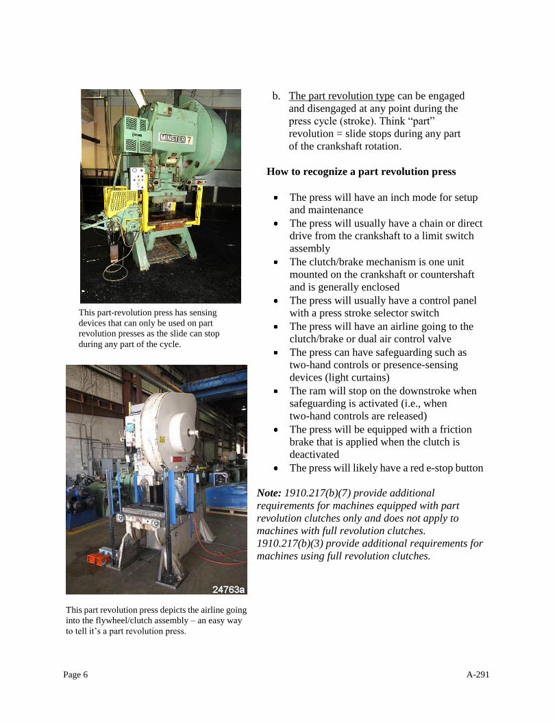
This part-revolution press has sensing
devices that can only be used on part
revolution presses as the slide can stop
during any part of the cycle.
b. The part revolution type can be engaged
and disengaged at any point during the
press cycle (stroke). Think “part”
revolution = slide stops during any part
of the crankshaft rotation.
How to recognize a part revolution press
The press will have an inch mode for setup
and maintenance
The press will usually have a chain or direct
drive from the crankshaft to a limit switch
assembly
The clutch/brake mechanism is one unit
mounted on the crankshaft or countershaft
and is generally enclosed
The press will usually have a control panel
with a press stroke selector switch
The press will have an airline going to the
clutch/brake or dual air control valve
The press can have safeguarding such as
two-hand controls or presence-sensing
devices (light curtains)
The ram will stop on the downstroke when
safeguarding is activated (i.e., when
two-hand controls are released)
The press will be equipped with a friction
brake that is applied when the clutch is
deactivated
The press will likely have a red e-stop button
Note: 1910.217(b)(7) provide additional
requirements for machines equipped with part
revolution clutches only and does not apply to
machines with full revolution clutches.
1910.217(b)(3) provide additional requirements for
machines using full revolution clutches.
This part revolution press depicts the airline going
into the flywheel/clutch assembly – an easy way
to tell it’s a part revolution press.
Page 7 A-291
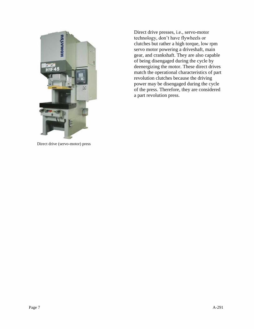
Direct drive presses, i.e., servo-motor
technology, don’t have flywheels or
clutches but rather a high torque, low rpm
servo motor powering a driveshaft, main
gear, and crankshaft. They are also capable
of being disengaged during the cycle by
deenergizing the motor. These direct drives
match the operational characteristics of part
revolution clutches because the driving
power may be disengaged during the cycle
of the press. Therefore, they are considered
a part revolution press.
Direct drive (servo-motor) press
Page 8 A-291
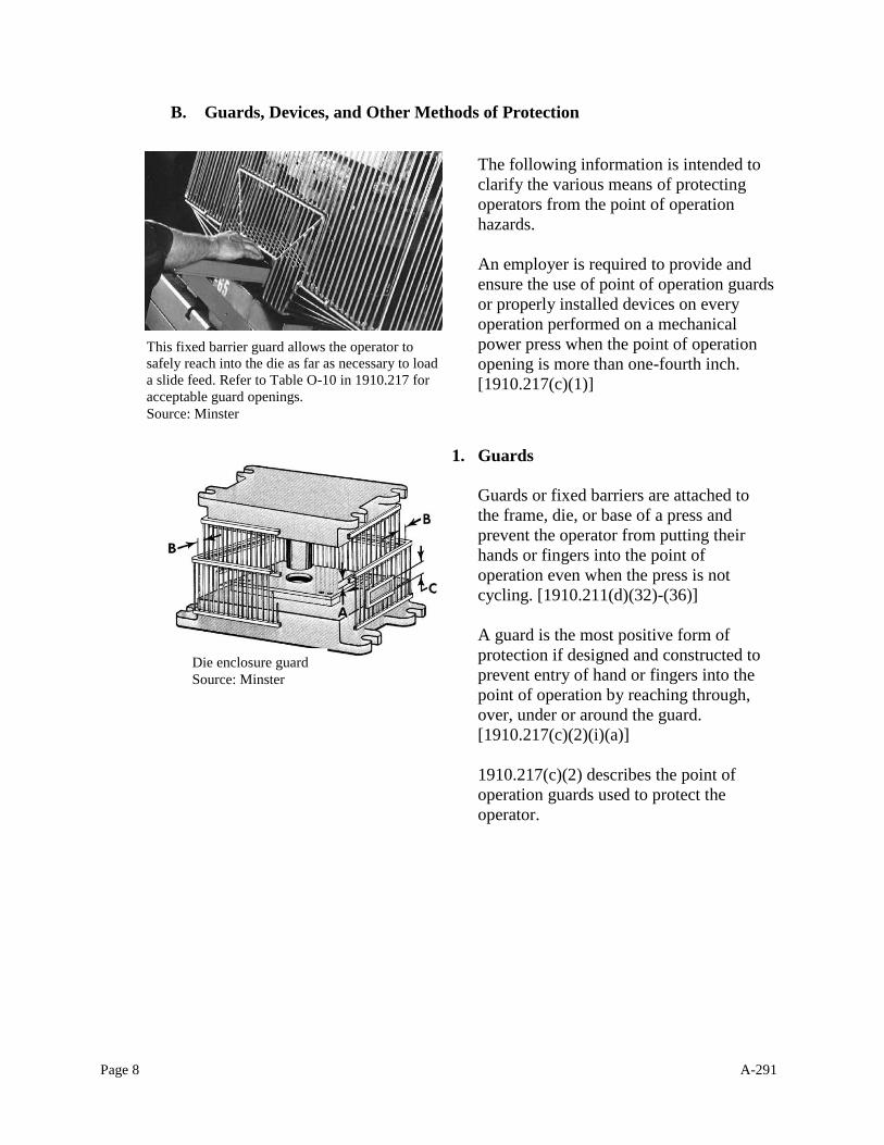
B. Guards, Devices, and Other Methods of Protection
The following information is intended to
clarify the various means of protecting
operators from the point of operation
hazards.
An employer is required to provide and
ensure the use of point of operation guards
or properly installed devices on every
operation performed on a mechanical
power press when the point of operation
opening is more than one-fourth inch.
[1910.217(c)(1)]
1. Guards
Guards or fixed barriers are attached to
the frame, die, or base of a press and
prevent the operator from putting their
hands or fingers into the point of
operation even when the press is not
cycling. [1910.211(d)(32)-(36)]
A guard is the most positive form of
protection if designed and constructed to
prevent entry of hand or fingers into the
point of operation by reaching through,
over, under or around the guard.
[1910.217(c)(2)(i)(a)]
1910.217(c)(2) describes the point of
operation guards used to protect the
operator.
Die enclosure guard
Source: Minster
This fixed barrier guard allows the operator to
safely reach into the die as far as necessary to load
a slide feed. Refer to Table O-10 in 1910.217 for
acceptable guard openings.
Source: Minster
Page 9 A-291
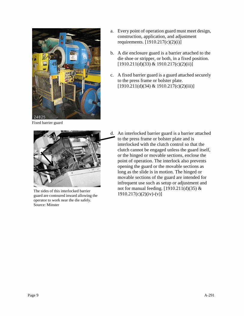
a. Every point of operation guard must meet design,
construction, application, and adjustment
requirements. [1910.217(c)(2)(i)]
b. A die enclosure guard is a barrier attached to the
die shoe or stripper, or both, in a fixed position.
[1910.211(d)(33) & 1910.217(c)(2)(ii)]
c. A fixed barrier guard is a guard attached securely
to the press frame or bolster plate.
[1910.211(d)(34) & 1910.217(c)(2)(iii)]
d. An interlocked barrier guard is a barrier attached
to the press frame or bolster plate and is
interlocked with the clutch control so that the
clutch cannot be engaged unless the guard itself,
or the hinged or movable sections, enclose the
point of operation. The interlock also prevents
opening the guard or the movable sections as
long as the slide is in motion. The hinged or
movable sections of the guard are intended for
infrequent use such as setup or adjustment and
not for manual feeding. [1910.211(d)(35) &
1910.217(c)(2)(iv)-(v)]
Fixed barrier guard.
The sides of this interlocked barrier
guard are contoured inward allowing the
operator to work near the die safely.
Source: Minster
Fixed barrier guard
Page 10 A-291
e. An adjustable barrier guard is attached
to the frame, press bed, bolster plate, or
die shoe and requires adjustment (by
authorized personnel only) for each job
or die setup. [1910.211(d)(36) &
1910.217(c)(2)(vi)]
f. If guards are installed and function
correctly, no other guarding or device is
required unless a combination is needed
to fully safeguard the point of
operation. A point of operation
enclosure is inadequate if it does not
meet the requirements of (c)(2) and
Table O-10 and can only be used in
conjunction with point of operation
devices. [1910.217(c)(2)(vii)]
2. Devices
Devices are press controls or attachments
that either stop normal press operation
before the operator can reach into the point
of operation or automatically withdraw
hands before the die closes if the operator's
hands are inadvertently within the point of
operation. Examples of such devices are
two-hand controls, gates or movable
barriers, pull-outs, restraints, and presence
sensing devices. [1910.211(d)(11)-(17) and
437-002-0242(1)]
Since fixed guarding is not always possible
due to the nature of an operation, devices
are acceptable as a means of protection
against point of operation hazards. If
devices are installed and function correctly,
no other guarding or device is required
unless a combination is needed to fully
safeguard the point of operation.
A presence-sensing device, or light curtain, on a
straight side mechanical power press.
Adjustable barrier guarding.
Source: Oregon OSHA
Page 11 A-291
1910.217(c)(3) describe the point of operation devices
used to protect the operator.
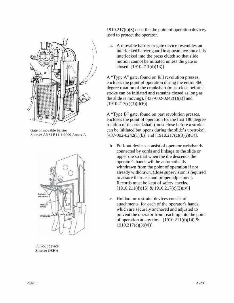
a. A movable barrier or gate device resembles an
interlocked barrier guard in appearance since it is
interlocked into the press clutch so that slide
motion cannot be initiated unless the gate is
closed. [1910.211(d)(13)]
A “Type A" gate, found on full revolution presses,
encloses the point of operation during the entire 360
degree rotation of the crankshaft (must close before a
stroke can be initiated and remains closed as long as
the slide is moving). [437-002-0242(1)(a)] and
[1910.217(c)(3)(i)(F)]
A “Type B” gate, found on part revolution presses,
encloses the point of operation for the first 180 degree
rotation of the crankshaft (must close before a stroke
can be initiated but opens during the slide’s upstroke).
[437-002-0242(1)(b)] and [1910.217(c)(3)(i)(G)].
b. Pull-out devices consist of operator wristbands
connected by cords and linkage to the slide or
upper die so that when the die descends the
operator's hands will be automatically
withdrawn from the point of operation if not
already withdrawn. Close supervision is required
to assure their use and proper adjustment.
Records must be kept of safety checks.
[1910.211(d)(15) & 1910.217(c)(3)(iv)]
c. Holdout or restraint devices consist of
attachments, for each of the operator's hands,
which are securely anchored and adjusted to
prevent the operator from reaching into the point
of operation at any time. [1910.211(d)(14) &
1910.217(c)(3)(vi)]
Pull-out device
Source: OSHA
Gate or movable barrier
Source: ANSI B11.1-2009 Annex A
Page 12 A-291
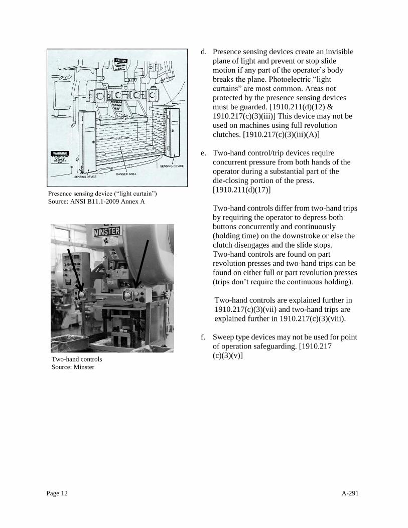
d. Presence sensing devices create an invisible
plane of light and prevent or stop slide
motion if any part of the operator’s body
breaks the plane. Photoelectric “light
curtains” are most common. Areas not
protected by the presence sensing devices
must be guarded. [1910.211(d)(12) &
1910.217(c)(3)(iii)] This device may not be
used on machines using full revolution
clutches. [1910.217(c)(3)(iii)(A)]
e. Two-hand control/trip devices require
concurrent pressure from both hands of the
operator during a substantial part of the
die-closing portion of the press.
[1910.211(d)(17)]
Two-hand controls differ from two-hand trips
by requiring the operator to depress both
buttons concurrently and continuously
(holding time) on the downstroke or else the
clutch disengages and the slide stops.
Two-hand controls are found on part
revolution presses and two-hand trips can be
found on either full or part revolution presses
(trips don’t require the continuous holding).
Two-hand controls are explained further in
1910.217(c)(3)(vii) and two-hand trips are
explained further in 1910.217(c)(3)(viii).
f. Sweep type devices may not be used for point
of operation safeguarding. [1910.217
(c)(3)(v)]
Presence sensing device (“light curtain”)
Source: ANSI B11.1-2009 Annex A
Two-hand controls
Source: Minster
Page 13 A-291
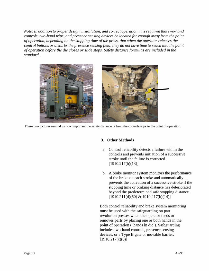
Note: In addition to proper design, installation, and correct operation, it is required that two-hand
controls, two-hand trips, and presence sensing devices be located far enough away from the point
of operation, depending on the stopping time of the press, that when the operator releases the
control buttons or disturbs the presence sensing field, they do not have time to reach into the point
of operation before the die closes or slide stops. Safety distance formulas are included in the
standard.
3. Other Methods
a. Control reliability detects a failure within the
controls and prevents initiation of a successive
stroke until the failure is corrected.
[1910.217(b)(13)]
b. A brake monitor system monitors the performance
of the brake on each stroke and automatically
prevents the activation of a successive stroke if the
stopping time or braking distance has deteriorated
beyond the predetermined safe stopping distance.
[1910.211(d)(60) & 1910.217(b)(14)]
Both control reliability and brake system monitoring
must be used with the safeguarding on part
revolution presses when the operator feeds or
removes parts by placing one or both hands in the
point of operation (“hands in die’). Safeguarding
includes two-hand controls, presence sensing
devices, or a Type B gate or movable barrier.
[1910.217(c)(5)]
These two pictures remind us how important the safety distance is from the controls/trips to the point of operation.
Page 14 A-291
4. Guarding by Location
Occasionally a machine without guards or devices
may be adequately safeguarded by reason of its
location, the location of other equipment, or the
location of the operator's station. To be guarded by
location, the hazardous area must be inaccessible to
all employees during the operating cycle. For
example, the feeding equipment of an automatically
fed press may function as a barrier in preventing
entry into the point of operation. Such
circumstances must be carefully analyzed to
determine if additional guards or devices are
needed.
5. Hand Feeding Tools
The use of hand feeding tools, regardless of their
length or size, does not replace guards or
devices. When used, close supervision is
essential because of the tendency to put such
tools aside to expedite feeding. The use of hand
tools also involves other hazards. For example,
should the die close while a hand tool is in the
point of operation, the operator could have the
tool wrenched from their grasp and be struck by
it, or forcibly jerked against the machine and
injured. [1910.211(d)(38)]
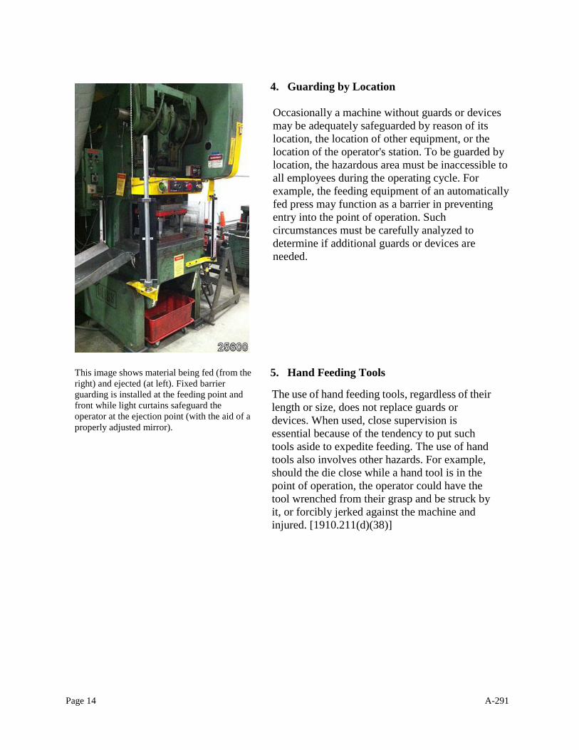
This image shows material being fed (from the
right) and ejected (at left). Fixed barrier
guarding is installed at the feeding point and
front while light curtains safeguard the
operator at the ejection point (with the aid of a
properly adjusted mirror).
Page 15 A-291
6. Diesetting - point of operation guarding
An employer is required to use dies and operating
methods to control or eliminate hazards. Furthermore,
they are required to furnish and enforce the use of
hand tools for freeing and removing stuck work or
scrap pieces from the die so employees don’t have to
reach into the point of operation.
a. 1910.217(c)(1)(i) requires protection of
employees through the use of point of operation
guards or devices, as defined in 1910.211(d)(11)
“Device” and 1910.211(d)(32) “Guard,” on every
operation performed on a mechanical power press.
Diesetters working on mechanical power presses
are covered by the provisions of 1910.217(c).
1910.217(d) covers the design, construction,
setting and feeding of dies. 1910.217
(d)(9)(i) was intended to clarify the
provisions of 1910.217(c) apply to diesetters
and point of operation guarding is required.
b. Mechanical power presses equipped with part
revolution clutches comply with point of
operation safeguarding for diesetters when an inch
mode is installed as specified in
1910.217(b)(7)(iv). Using an inch mode according
to 1910.217(b)(7)(iv) constitutes use of a "device"
within the meaning of 1910.211(d)(11).
c. Full revolution mechanical power presses cannot
normally be safeguarded with guards during
diesetting operations. However, in instances when
guards are not applicable and for presses provided
with barring holes in the flywheel, the diesetter is
protected if:
The power press is deenergized and the
flywheel is brought to rest.
The prime mover power to the power press
is locked out.
The slide is moved by manually turning the
crankshaft with the aid of a turnover bard.
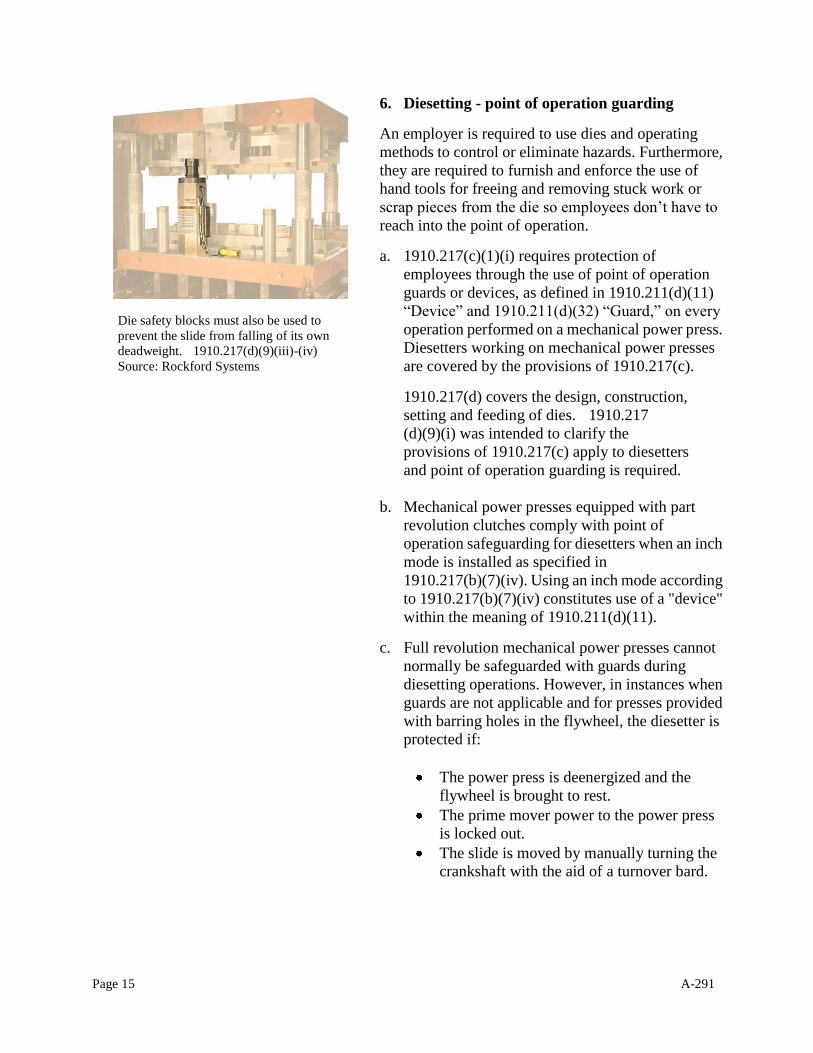
Die safety blocks must also be used to
prevent the slide from falling of its own
deadweight. 1910.217(d)(9)(iii)-(iv)
Source: Rockford Systems

Page 16 A-291
d. On some full revolution mechanical power presses,
primarily those over 60 tons, the slide cannot be
moved manually during diesetting. Safeguarding is
provided if:
They are equipped with a jog mode of
operation.
The flywheel is brought to rest and the clutch
is engaged before the drive motor is jogged.
The jog control requires two-hand operation or
the jog control is single control protected
against accidental actuation and located so that
the worker cannot reach into the
point-of-operation.
e. For full revolution mechanical power presses,
safeguarding of the diesetter, as set forth in
paragraphs c and d, constitutes a "device" in
1910.211(d)(11).
f. For presses equipped with a turnover bar, the
employer must provide means to ensure removal of
the turnover bar from the bar hole before the press
can be energized. Examples of methods for ensuring
the removal of the turnover bar from the bar hole are
use of spring action on the end of the bar or bar
storage pockets that incorporate an interlock switch.
[1910.217(d)(9)(ii) and ANSI B11.1(2001) 9.2.5]
Spring-loaded turnover bar.
Source: Rockford Systems
Page 17 A-291
ACTION
For compliance purposes, Oregon OSHA field staff will interpret the requirements of
1910.217 in the following manner:
Mechanically powered machines that shear, punch, form, or assemble metal or
other material by means of tooling or dies attached to slides, as defined by
Division 2/O 1910.211(d)(46) and identified by their respective manufacturers
as mechanical power presses, are regulated under 1910.217
When diesetters are operating a mechanical power press, such as running test and
production parts, diesetting, or troubleshooting, they must be protected by point
of operation guards or devices. Failure to provide such safeguards constitutes a
violation of 1910.217(c)(1)(i).
When diesetters operate a mechanical power press equipped with a part
revolution clutch, and the inch mode is not installed per 1910.217(b)(7)(iv), a
violation exists and a citation will be issued if no alternative safeguard is
provided.
On mechanical power presses equipped with part revolution clutches, turnover
bar operations must comply with 1910.217(b)(7)(xv).
When pullout and holdout or restraint devices alone are used on mechanical
power presses with either a part or full revolution-type clutch, they are sufficient
protection within the intent of these standards when they meet all other
requirements as set forth in 1910.217(c)(3)(iv) and 1910.217(c)(3)(vi).
MACHINES OTHER THAN MECHANICAL POWER PRESSES
BACKGROUND
Press brakes, ironworkers, platen presses, shears, and other press-like machines
powered by hydraulic, pneumatic, or electrical means may have similar construction
and function to mechanical power presses but are covered under 1910.212, General
Requirements for All Machines. 1910.217 is limited in scope to mechanical power
presses only.
Many of these machines have respective ANSI standards – please refer to the list on
page two. Although these ANSI standards have not been adopted, they provide
useful guidance for compliance officers in evaluating and correcting hazards.
Page 18 A-291
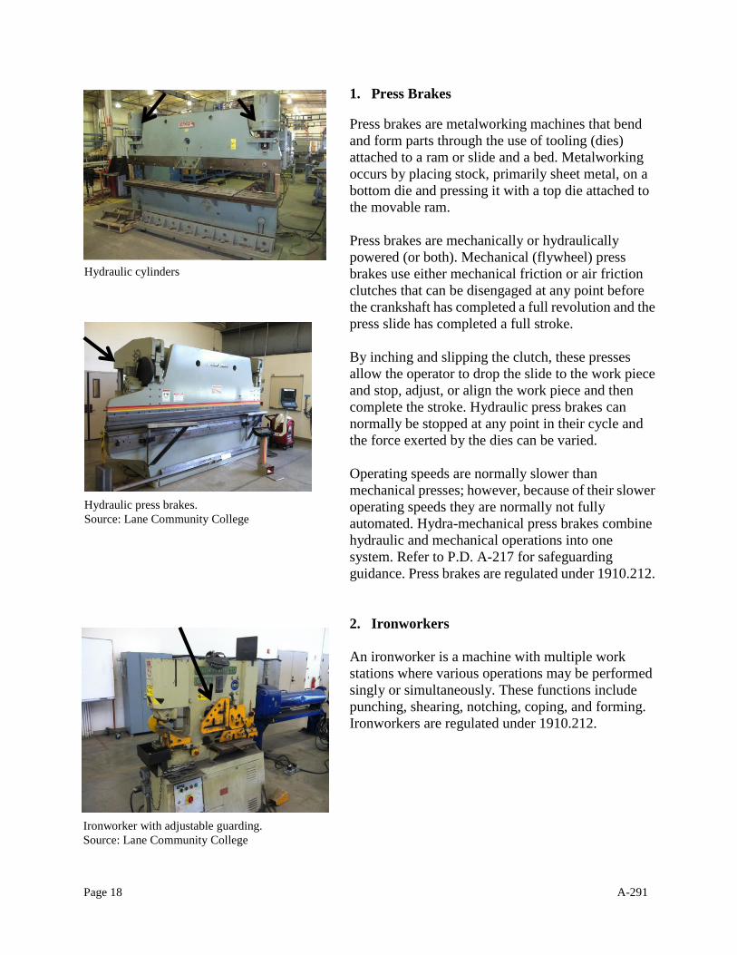
1. Press Brakes
Press brakes are metalworking machines that bend
and form parts through the use of tooling (dies)
attached to a ram or slide and a bed. Metalworking
occurs by placing stock, primarily sheet metal, on a
bottom die and pressing it with a top die attached to
the movable ram.
Press brakes are mechanically or hydraulically
powered (or both). Mechanical (flywheel) press
brakes use either mechanical friction or air friction
clutches that can be disengaged at any point before
the crankshaft has completed a full revolution and the
press slide has completed a full stroke.
By inching and slipping the clutch, these presses
allow the operator to drop the slide to the work piece
and stop, adjust, or align the work piece and then
complete the stroke. Hydraulic press brakes can
normally be stopped at any point in their cycle and
the force exerted by the dies can be varied.
Operating speeds are normally slower than
mechanical presses; however, because of their slower
operating speeds they are normally not fully
automated. Hydra-mechanical press brakes combine
hydraulic and mechanical operations into one
system. Refer to P.D. A-217 for safeguarding
guidance. Press brakes are regulated under 1910.212.
2. Ironworkers
An ironworker is a machine with multiple work
stations where various operations may be performed
singly or simultaneously. These functions include
punching, shearing, notching, coping, and forming.
Ironworkers are regulated under 1910.212.
Hydraulic press brakes.
Source: Lane Community College
Hydraulic cylinders
Ironworker with adjustable guarding.
Source: Lane Community College
Page 19 A-291
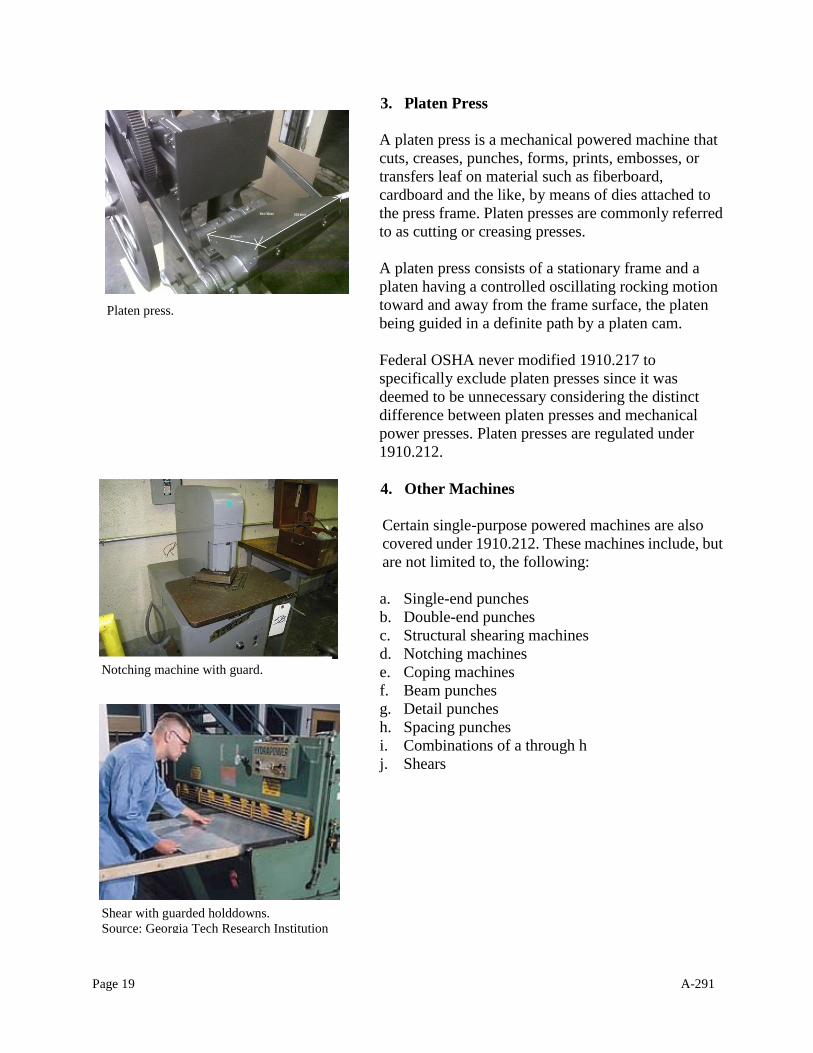
3. Platen Press
A platen press is a mechanical powered machine that
cuts, creases, punches, forms, prints, embosses, or
transfers leaf on material such as fiberboard,
cardboard and the like, by means of dies attached to
the press frame. Platen presses are commonly referred
to as cutting or creasing presses.
A platen press consists of a stationary frame and a
platen having a controlled oscillating rocking motion
toward and away from the frame surface, the platen
being guided in a definite path by a platen cam.
Federal OSHA never modified 1910.217 to
specifically exclude platen presses since it was
deemed to be unnecessary considering the distinct
difference between platen presses and mechanical
power presses. Platen presses are regulated under
1910.212.
4. Other Machines
Certain single-purpose powered machines are also
covered under 1910.212. These machines include, but
are not limited to, the following:
a. Single-end punches
b. Double-end punches
c. Structural shearing machines
d. Notching machines
e. Coping machines
f. Beam punches
g. Detail punches
h. Spacing punches
i. Combinations of a through h
j. Shears
Notching machine with guard.
Platen press.
Shear with guarded holddowns.
Source: Georgia Tech Research Institution
Page 20 A-291
ACTION
For compliance purposes, Oregon OSHA field staff will interpret the rule
requirements in the following manner:
Machines such as press brakes, iron workers, shears, hydraulic and
pneumatic power presses, and platen presses are regulated under 1910.212
Consult the respective ANSI standards when attempting to enforce a citation
EFFECTIVE DATE:
This directive is effective immediately and will remain in effect until cancelled or
superseded.
Several images in this directive were taken from the Internet and appear to be actual
installations. Potential violations may exist in some of these images but are being provided for
identification and demonstrative purposes only and should not be relied upon for evaluating
proper methods of safeguarding.
The following pages depict various machinery to aid in the proper recognition and applicability
of 1910.212 and 1910.217.
Page 21 A-291
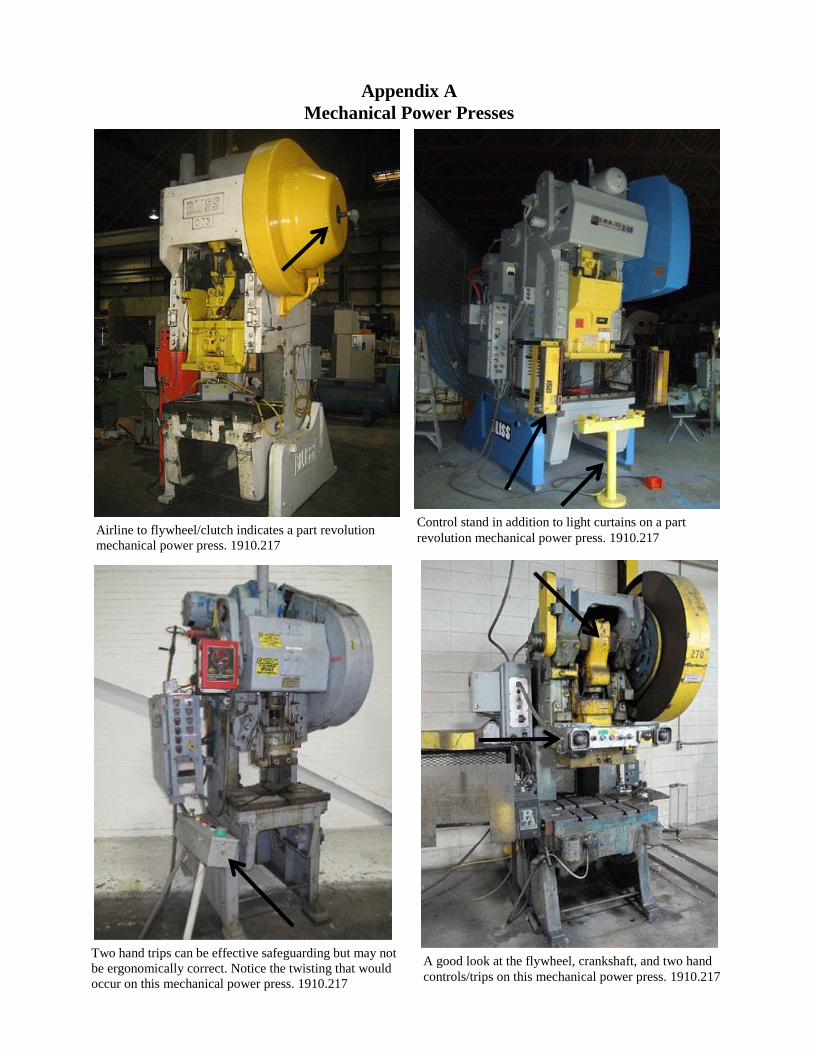
Airline to flywheel/clutch indicates a part revolution
mechanical power press. 1910.217
Two hand trips can be effective safeguarding but may not
be ergonomically correct. Notice the twisting that would
occur on this mechanical power press. 1910.217
Control stand in addition to light curtains on a part
revolution mechanical power press. 1910.217
A good look at the flywheel, crankshaft, and two hand
controls/trips on this mechanical power press. 1910.217
Appendix A
Mechanical Power Presses
Page 22 A-291
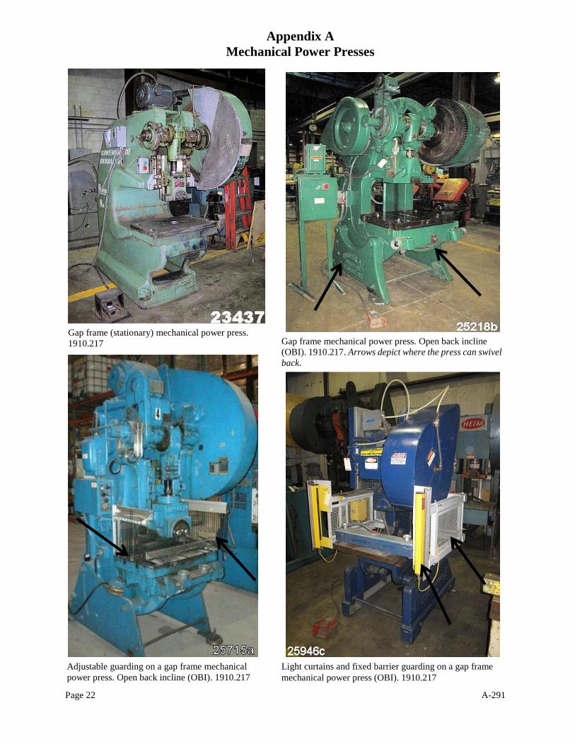
Gap frame mechanical power press.“Open back
incline (OBI)”. 1910.217. Arrows depict where the
press can swivel back.
Adjustable guarding on a gap frame mechanical
power press. Open back incline (OBI). 1910.217
Gap frame (stationary) mechanical power press.
1910.217
Light curtains and fixed barrier guarding on a gap frame
mechanical power press (OBI). 1910.217
Gap frame mechanical power press. Open back incline
(OBI). 1910.217. Arrows depict where the press can swivel
back.
Appendix A
Mechanical Power Presses
Page 23 A-291
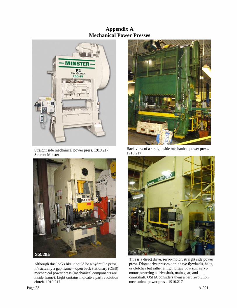
Straight side mechanical power press. 1910.217
Source: Minster
Back view of a straight side mechanical power press.
1910.217
Although this looks like it could be a hydraulic press,
it’s actually a gap frame – open back stationary (OBS)
mechanical power press (mechanical components are
inside frame). Light curtains indicate a part revolution
clutch. 1910.217
This is a direct drive, servo-motor, straight side power
press. Direct drive presses don’t have flywheels, belts,
or clutches but rather a high torque, low rpm servo
motor powering a driveshaft, main gear, and
crankshaft. OSHA considers them a part revolution
mechanical power press. 1910.217
Appendix A
Mechanical Power Presses
Page 24 A-291
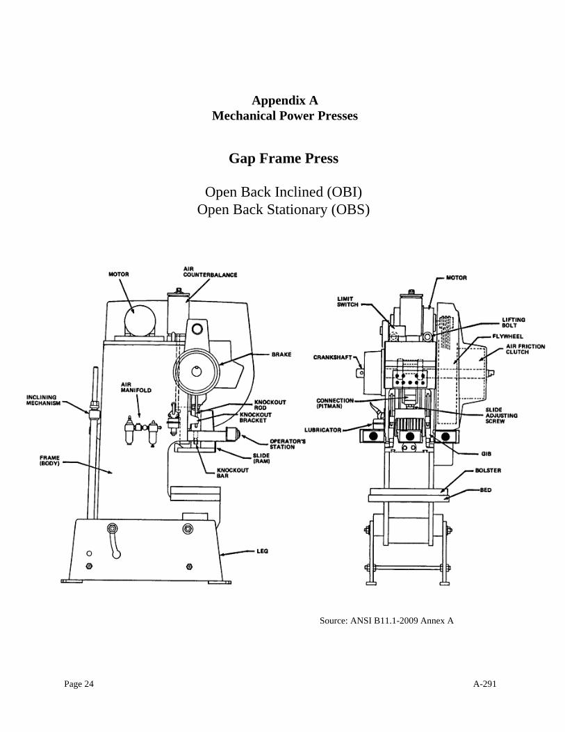
Gap Frame Press
Open Back Inclined (OBI)
Open Back Stationary (OBS)
Appendix A
Mechanical Power Presses
Source: ANSI B11.1-2009 Annex A
Page 25 A-291
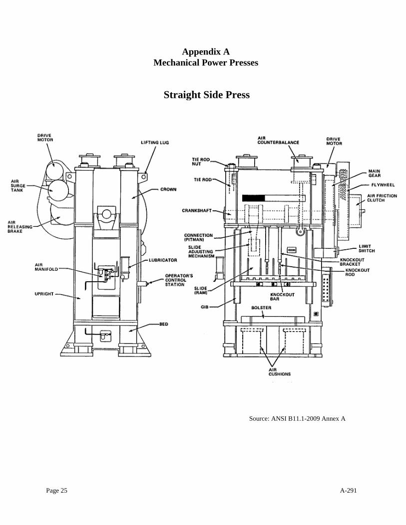
Straight Side Press
Appendix A
Mechanical Power Presses
Source: ANSI B11.1-2009 Annex A
Page 26 A-291
Appendix B
Additional Safeguarding Options for
Mechanical Power Presses
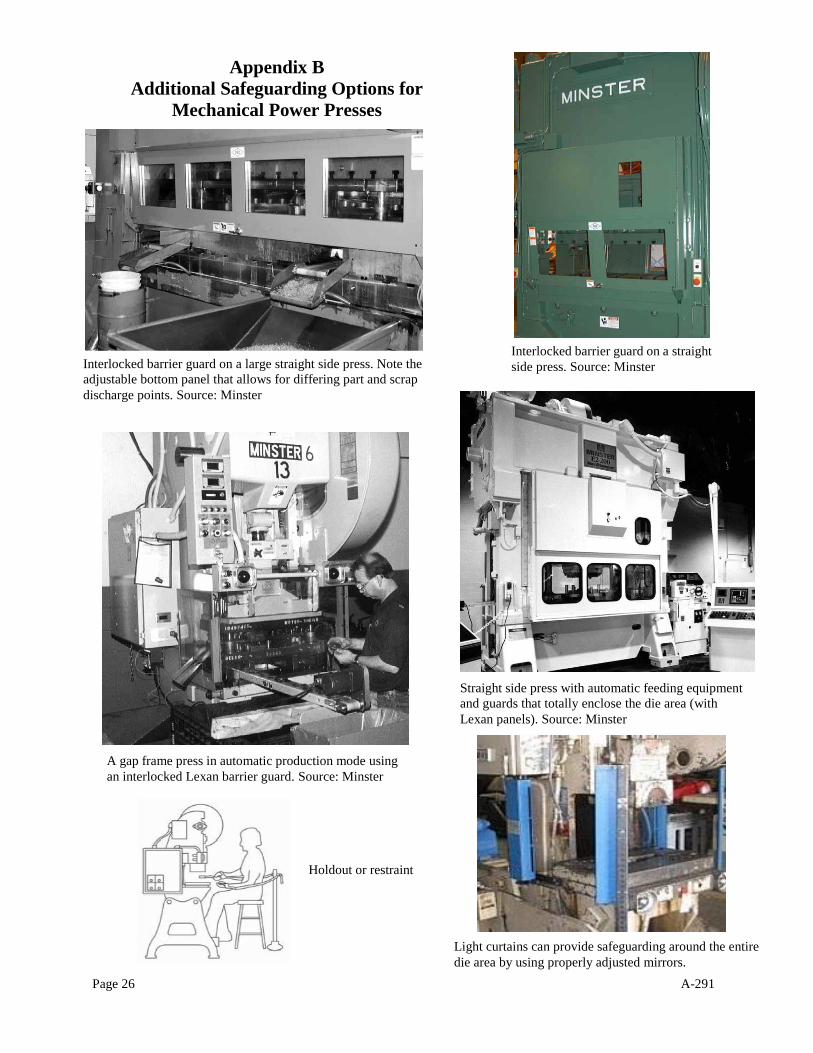
Interlocked barrier guard on a large straight side press. Note the
adjustable bottom panel that allows for differing part and scrap
discharge points. Source: Minster
Interlocked barrier guard on a straight
side press. Source: Minster
A gap frame press in automatic production mode using
an interlocked Lexan barrier guard. Source: Minster
Light curtains can provide safeguarding around the entire
die area by using properly adjusted mirrors.
Straight side press with automatic feeding equipment
and guards that totally enclose the die area (with
Lexan panels). Source: Minster
Holdout or restraint
Page 27 A-291
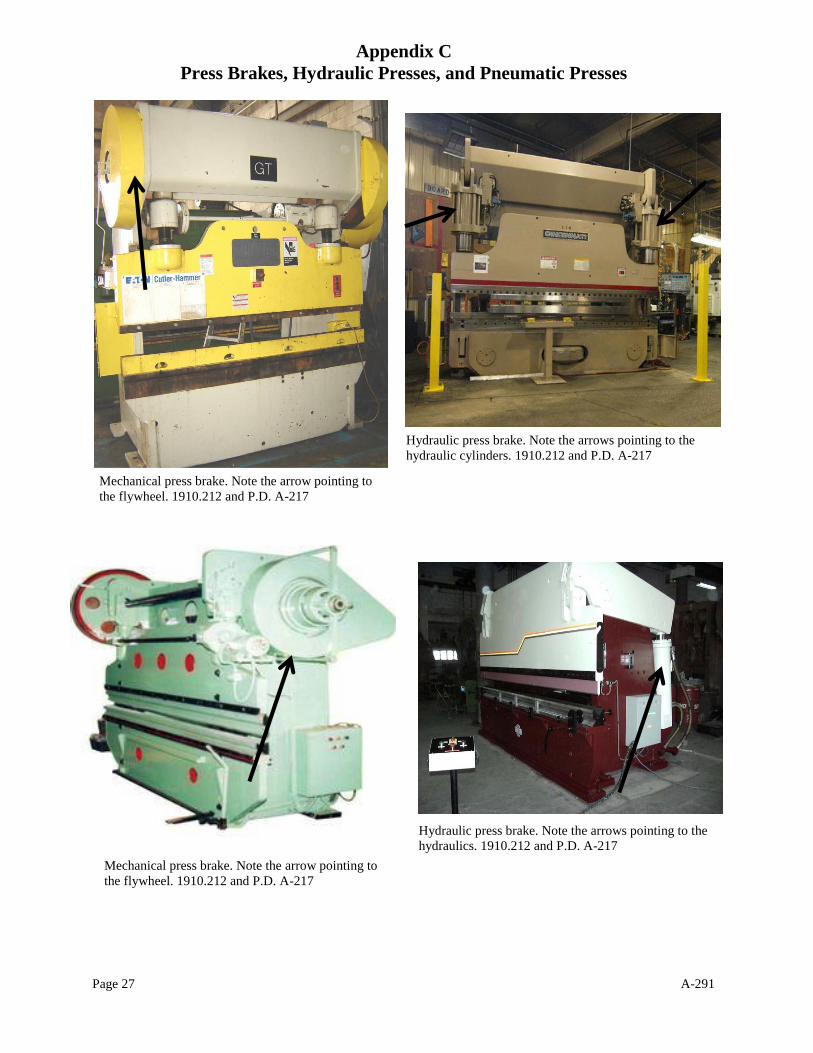
Mechanical press brake. Note the arrow pointing to
the flywheel. 1910.212 and P.D. A-217
Mechanical press brake. Note the arrow pointing to
the flywheel. 1910.212 and P.D. A-217
Hydraulic press brake. Note the arrows pointing to the
hydraulics. 1910.212 and P.D. A-217
Hydraulic press brake. Note the arrows pointing to the
hydraulic cylinders. 1910.212 and P.D. A-217
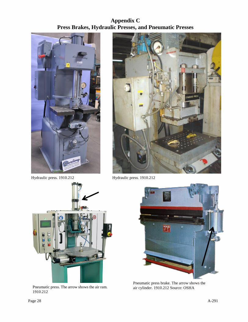
Appendix C
Press Brakes, Hydraulic Presses, and Pneumatic Presses
Page 28 A-291
Hydraulic press. 1910.212
Pneumatic press. The arrow shows the air ram.
1910.212
Hydraulic press. 1910.212
Pneumatic press brake. The arrow shows the
air cylinder. 1910.212 Source: OSHA
Appendix C
Press Brakes, Hydraulic Presses, and Pneumatic Presses