Embed Size (px)
Citation preview
Wells, S. A. and Sartbaeva, A. (2015) GASP:software for geometric simulations of flexibility in polyhedral and molecular framework structures. Molecular Simulation, 41 (16-17). pp. 1409-1421. ISSN 0892-7022
Link to official URL (if available): http://dx.doi.org/10.1080/08927022.2015.1032277
Opus: University of Bath Online Publication Store
http://opus.bath.ac.uk/
This version is made available in accordance with publisher policies. Please cite only the published version using the reference above.
See http://opus.bath.ac.uk/ for usage policies.
Please scroll down to view the document.

March 16, 2015 22:5 Molecular Simulation WellsSartbaevaMolSimGeomSimv2.0
Molecular SimulationVol. 00, No. 00, Month 2009, 1–18
RESEARCH ARTICLE
GASP: software for geometric simulations of flexibility in polyhedral and
molecular framework structures
Stephen A. Wellsa∗ and Asel Sartbaevaa
aDepartment of Chemistry, University of Bath, Claverton Down, Bath BA2 7AY
(Received 00 Month 200x; final version received 00 Month 200x)
Template-based geometric simulation is a specialised method for modeling flexible framework structuresmade up of rigid units using a simplified, localised physical model. The strengths of the method are its abil-ity to handle large all-atom structural models rapidly and at minimal computational expense, and to provideinsights into the links between local bonding and steric geometry and global flexibility. We review the implemen-tation of geometric simulation in the ‘GASP’ software, and its application to the study of materials includingzeolites, perovskites and metal-organic frameworks (MOFs). The latest version (5) of GASP has significantimprovements and extensions, in particular an improved algorithm for relaxation of atomic positions, and thecapacity to handle both polyhedral and molecular structural units. GASP is freely available to researchers.
Keywords: Geometric simulation; polyhedral rotation; zeolite; perovskite; metal-organic framework
1 Introduction
Template-based geometric simulation is a specialised method for the study of flexible frameworks.Such frameworks are composed of relatively rigid subunits (clusters) connected by relativelyflexible linkages; that is, the energetic penalty for distortions of the clusters is an order ofmagnitude greater than the energetic penalty for flexion in the linkage. In the case of a three-dimensional framework silicate, such as quartz or a siliceous zeolite, the SiO4 tetrahedra are therelatively rigid clusters, while the Si–O–Si bridge is a more flexible linkage,as indicated by thewide range of Si–O–Si angles observed in different framework silicate structures [1, 2]. In a metal-organic framework (MOF), both the organic linker molecules and the coordination polyhedraaround metal centres may be treated as rigid clusters, with the potential for flexibility at theinterface between them.
The central concept of geometric simulation is to represent the bonding within rigid units,not by a collection of two-, three- and four-body empirical potentials, but by a template or‘ghost’ representing the ideal bonding geometry of the cluster, either polyhedral or molecular.Harmonic constraints linking each atom to the corresponding vertex of a template then penaliseany deviation from the ideal cluster geometry [3, 4]. In the course of a ‘geometric relaxation’, thepositions of atoms and templates are mutually updated to minimise both deviations from clustergeometry and steric overlap of atomic spheres. Thus the method implements a simple physicalmodel which includes the strongest, most local forces in the system — covalent bonding andsteric exclusion — while neglecting all longer-ranged interactions. The method is computationallyrobust and inexpensive, with results typically being generated in seconds or minutes on a singleprocessor, e.g. on a laptop or desktop computer. This makes the method particularly suitable for
∗Corresponding author. Email: [email protected]
ISSN: 0892-7022 print/ISSN 1029-0435 onlinec© 2009 Taylor & FrancisDOI: 10.1080/0892702YYxxxxxxxxhttp://www.informaworld.com

March 16, 2015 22:5 Molecular Simulation WellsSartbaevaMolSimGeomSimv2.0
2 Wells and Sartbaeva
the investigation of large system sizes and for the rapid exploration of hypothetical conditionsof strain and/or extraframework contents in porous frameworks, on its own or as an adjunt tosimulations with conventional methods. The process of fitting cluster geometries to groups ofatoms can also be used as an analysis tool to investigate structural models produced by othermethods, particularly Reverse Monte Carlo (RMC) modelling based on total scattering data[5–7].
The geometric simulation approach operates at an entirely different level of theory from ab-initio electronic structure and all-atom empirical-potential methods; it does not generate adetailed energy landscape, but rather explores framework geometries that satisfy local stericand bonding geometric requirements. This simplification can in fact be a powerful generator ofinsight, revealing the significance or otherwise of the long-range (charge, polarity) effects thatare deliberately excluded from the geometric simulation model.
1.1 Scope of our review
Essential mathematical details in the implementation of geometric simulation are discussed (sec-tion 2) for the benefit of current and future users and for those wishing to make use of geometricsimulation concepts in their own software. We will take a brief overview (section 3) of someof the previous applications of geometric simulation to polyhedral mineral structures — suchas aluminosilicates, including zeolites, and perovskites — and to proteins, viewed as molecularframeworks. These topics are discussed in additional detail in our recent review [8]. In the currentwork we focus on recent developments, especially (i) improvements and extensions in currentgeometric simulation software, (ii) the concepts of the intrinsic and extrinsic flexibility windowsin a zeolite (section 4), and (iii) the application of geometric simulation to MOFs (section 5).
1.2 Software implementation
Geometric simulation for periodic framework structures is implemented in a piece of softwaretitled ‘GASP’, for ‘Geometric Analysis of Structural Polyhedra’. The name ‘GASP’ is intendedas a respectful pun on the widely used and extremely comprehensive ‘GULP’ simulation package[9]. Version 1 of GASP was written in Fortran 90; subsequent versions have been written in C++.In 2014 GASP was rewritten from scratch (in C++) to improve program workflow, implementan improved algorithm for the update of atomic positions, remove unwanted legacy features,and provide a more legible and consistent input and control format. This current version, GASPv.5, consists of the main GASP code and a small suite of associated utility programs; it hasbeen successfully compiled and run under Windows, Linux and Mac OSX environments. In itscurrent form GASP requires an input structure in XTL format, and a control input file containingparameters and commands. GASP is freely available to researchers. Prospective users shouldemail the corresponding author to receive a copy of the code, a set of example inputfiles, and a comprehensive manual.
2 Mathematical notes: bivectors, rotors and fitting
The heart of the geometric simulation method is the fitting of a template to a cluster of atoms.Fundamentally this is a matter of finding a rotation which matches the orientation of the templateand cluster. In geometric simulations the rotation is described using the bivector mathematicsof geometric (Clifford) algebra [10]. Since this approach is not commonly encountered in thephysical sciences literature we will briefly go over the essential concepts. The process of fittinga template to a group of atoms, and of relaxing the atoms to fit the templates, is illustratedschematically in Figure 1.

March 16, 2015 22:5 Molecular Simulation WellsSartbaevaMolSimGeomSimv2.0
Molecular Simulation 3
(a) (b)
(c) (d)
Figure 1. Schematic illustration in 2D of the geometric simulation process. (a) two approximately trigonal, vertex-sharingclusters in a 2D framework. (b) initial construction of a template with ideal geometry over each cluster; mismatches areidentified between each atom and corresponding vertex. (c) rotational fitting of templates by minimisation of mismatches;this generally leaves some residual mismatch, as shown for the shared vertex atom. (d) relaxation of atomic positions toreduce mismatches. Geometric analysis constitutes steps (a)–(c). Geometric simulation proceeds by iterative repetition ofsteps (c),(d).
2.1 Geometric algebra in two dimensions
In conventional vector calculus, the mathematics of a two-dimensional plane would be describedin terms of scalar quantities (based on the unit scalar, 1) and vector quantities (based on twoperpendicular unit vectors e1 and e2). To these, Clifford algebra adds an additional entity: adirected area element, the bivector B = e1e2. For clarity we shall capitalise variables rep-resenting bivectors and higher-grad objects. Vectors in Clifford algebra can be multiplieddirectly; the product of perpendicular vectors is a bivector while that of parallel vectors is ascalar, e.g. e1e1 = 1 = e2e2. The bivector is directed in the sense that B = e1e2 = −e2e1. Thebivector can act to rotate the basis vectors by multiplication either from the left, rotating ninetydegrees clockwise (Be1 = e1e2e1 = −e2 ; Be2 = e1e2e2 = e1) or the right, rotating anticlockwise(e1e1e2 = e2; e2e1e2 = −e1).
The 2D bivector also squares to -1 (B2 = e1e2 × e1e2 = −e1e1e2e2 = −1) and so it ex-ponentiates exactly like the conventional scalar unit imaginary i. We can write the identityexp(Bθ) = cos θ +B sin θ. This exp(Bθ) object can act to rotate a vector through θ radians. It
is convenient to define a rotor operator R = exp(−Bθ/2) and its ‘reverse’ R = exp(+Bθ/2), sothat rotation of an arbitrary vector v anticlockwise by θ radians is achieved by the two-sidedoperation RvR. The rotor R is an example of a ”multivector” object, as it containsscalar and bivector components.
2.2 Geometric algebra and rotations in three dimensions
The general utility of this approach becomes clearer once we go from two to three dimensions.In this case we develop a geometric algebra of eight entities; from the scalar 1 and unit vectorse1, e2, e3 we develop three bivectors B3 = e1e2, B1 = e2e3, B2 = e3e1, and a directed volume

March 16, 2015 22:5 Molecular Simulation WellsSartbaevaMolSimGeomSimv2.0
4 Wells and Sartbaeva
element, the pseudoscalar J = e1e2e3. The pseudoscalar can convert between a bivector andits Hodge dual (perpendicular vector), e.g. JB3 = e1e2e3 × e1e2 = −e3 etc.. A bivector rotatesvectors in its own plane and generates the pseudoscalar with a perpendicular vector. Our 2Drotor R containing the bivector e1e2, if applied to a general vector, will act to rotate the in-plane(e1 and e2) components of the vector, but will leave the e3 component quite unaffected — all
components of e1e2e3 cancel when RvR is evaluated.The even-grade objects (scalar and bivectors) in 3D have an algebra very similar to Hamilton’s
quaternions: B2i = −1, BiBj = −Bk. A general plane can be represented by a unit bivector B
with components c1B1 + c2B2 + c3B3; by the Hodge dual this is the plane normal to the vectorc1e1 + c2e2 + c3e3. Thus a general rotation can be carried out by a rotor R = exp(−Bθ/2).
Within the geometric analysis software GASP, a rotation is parametrised by the three com-ponents of a bivector Bθ = 2B sin θ
2 ; effectively a ‘vector’ bθ whose direction is the rotation axisand whose magnitude is very close to the rotation magnitude in radians.
2.3 Rotations of polyhedra and clusters
The fitting operation carried out by GASP for each cluster in a framework — e.g. an SiO4
polyhedron — involves minimising the mismatch between the positions of a set of vertices in atemplate, and the matching set of vertices based on the current positions of the atoms makingup the cluster. It is trivial to make the centres of the template and cluster coincident, so we onlyneed to find a suitable rotation. For each vertex q, we construct a vector pq from the (Cartesian)position of the centre to the position of the vertex in the template. It is convenient to constructpq as a function of the rotation ‘vector’ b. We can then consider the vector mismatch εq betweenpq(b) and the matching vector pq′ based on the current positions of the atoms in the cluster:εq = pq(b)− pq′. Thus for example the x component of εq is calculated as:
εx = pqx(1− 1
2(b2y + b2z)) + pqy(−Cbz +
1
2bxby) + pqz(Cby +
1
2bxbz)− pq′x (1)
where C is the scalar quantity
C =√
(1.0− 1
4(b2x + b2y + b2z)) (2)
equal to cos θ2 . Expressions for εy,z can be obtained by cyclic permutation of components of b,and are fully tabulated in reference [3].
A rotation is found by minimising a penalty function E =∑qε2q as a function of the rotation
parameters b for this cluster. The gradient of E with respect to the components of b is easilyconstructed analytically, and the full expression is tabulated in reference [3]. GASP uses thesecant method to minimise E by finding the zero of the gradient, thus identifying the rotationparameters b which best fit the template to the cluster. The equations for εq can now be used,setting pq′ = 0, to generate a rotated version of the template, superimposed on the cluster. Thisprocess of fitting is illustrated in the method schematic, Figure 1b,c.
The residual differences between template and cluster positions can be used to quantify thedistortion of the cluster from the ideal geometry defined by the template (see Figure 1c). It isa useful feature that this distortion is a distance measure (that is, distortion can be describedby the mean-squared or RMS vertex–atom mismatch) which is easier to grasp than a collectionof bond length and angle measurements. Indeed the first application of GASP was as a form ofgeometric analysis, to assess large structural models of polyhedral framework materials producedby Reverse Monte Carlo modelling based on total scattering data (see section 3.1).

March 16, 2015 22:5 Molecular Simulation WellsSartbaevaMolSimGeomSimv2.0
Molecular Simulation 5
During the initial development of geometric simulation, applied to regular poly-hedral structural units, it was typical for the centre–vertex vectors pq to correspondto interatomic bonds such as Si–O, with the centre position of the cluster coincidingwith the position of the central Si atom. However, there is no requirement in themathematics of the fitting process for this to be the case. The method can equallywell be applied to a group of atoms representing a molecular fragment, for examplea peptide unit in a protein backbone. In this case, the centre of the cluster is simplythe geometric centre of the positions of member atoms, and need not coincide withthe position of any individual atom. The centre-vertex vectors pq then do not liealong interatomic bonds, but simply describe the positions of all the atoms in thecluster.
A further process — geometric relaxation — can be carried out by seeking to minimise theseresidual differences as a function of the positions of both atoms and templates. If this is to bedone we must consider how to relax the position of an individual atom, which may belong tomultiple clusters and thus have multiple ‘ideal’ positions, and which may furthermore be in stericcontact with other atoms.
2.4 Relaxation of atomic positions
We now consider an atom A which belongs to n clusters and which is in steric overlap with mother atoms (clearly if n,m are both zero then nothing need be done). For each cluster i thereis a vertex position which the atom should move towards, while each contact j is an objectwhich the atom should move away from. We note that the most significant radius for zeoliteframeworks is that of the tetrahedral oxygen atoms, for which we use a standard radius of1.35A[11]; steric radii for all elements present in the input structure can be defined by the userin the program control input file. The neighbour search for contacts is short-range andhighly localised, and can therefore be undertaken using a coarse-gridding approachwhich scales linearly with system size. Atoms are assigned to cells in a coarse gridwith spacing of order 4A. Contacts need only be searched for in the same cell andits immediately adjacent neighbouring cells. Our goal is to generate a displacement vectorfor the atom so that we can update its position. Previous versions of GASP constructed thisdisplacement by averaging a set of vectors representing (i) movement of the atom to a vertexposition and (ii) movement directly away from a steric contact until just out of contact distance.The most recent version of GASP, however, uses an improved approach which has not previouslybeen reported in detail, and which we will now derive.
We place the atom A at the origin of a temporary Cartesian coordinate system, so that itcurrently has a position r0 = (0, 0, 0). During the fitting it will develop a position r = (x, y, z)which is the displacement vector we require. Each template vertex to which the atom belongs hasa position ri, and each contact atom j has a position rj . The ri, rj do not change during this partof the process, that is, ri, rj are parameters while r is variable. The vector from a vertex to theatom A is thus ∆ri = r− ri, and the vector from a contact atom to the atom A is ∆rj = r− rj .The ‘penalty’ for the offset between the atom and a vertex position is |∆ri|2 = (r − ri)
2; aharmonic term going to zero when the atom A is coincident with the vertex i.
For steric contacts the situation is a little more complicated, as we must consider the currentdistance between the atoms (|∆rj |) and their ideal contact distance dj , which is the sum of theirsteric radii. The distance by which the atoms overlap is dj − |∆rj | and an appropriate harmonic
penalty is this distance squared, which is d2j − 2dj |∆rj |+ |∆rj |2.
The net penalty for our atom A is thus
P =∑i
|∆ri|2 +∑j
(d2j − 2dj |∆rj |+ |∆rj |2) (3)

March 16, 2015 22:5 Molecular Simulation WellsSartbaevaMolSimGeomSimv2.0
6 Wells and Sartbaeva
and we seek a position r for the atom that will minimise P by making ∇P = 0. Consideringfor example the x component of this gradient, and noting that ∂x |∆rk|2 = 2(x − xk) while∂x |∆rk| = (x− xk)/ |∆rk|, we find that ∂xP = 0 when
∑i
(x− xi) +∑j
(x− xj)(1−dj|∆rj |
) = 0. (4)
We can now seek a suitable value of x (and y, z) by iterating towards a self-consistent solution,using an ‘old’ value of x and |∆rj | to generate a ‘new’ value of x. Beginning with our initialposition at the origin, and the corresponding values of |∆rj |, we use this rearrangement of thepreceding equation:
xNEW =
∑i xi +
∑j xj(1−
dj|∆rj,OLD|)∑
i 1 +∑
j(1−dj
|∆rj,OLD|)(5)
and iterate until xNEW and xOLD are effectively identical. Of course y, z must likewise beupdated at the same time, as |∆rj | depends on x, y, z.
A few noteworthy features of this approach are as follows.(i) If an atom has no steric contacts, it is moved in a single step to the mean position of all
the template vertices to which it belongs, as desired.(ii) As constructed the steric exclusion constraint is holonomic, so the function also penalises
the separation of atom A from a contact j by more than the ideal contact distance dj . This doesnot offer a difficulty in practice, since if the atoms do move out of contact, they will not be foundin contact at the start of the next cycle of relaxation, and so no further penalty will apply.
(iii) The derivation above gives equal weight to the vertex (i) terms and the steric overlap (j)terms. In practice the terms can be weighted by a user-defined damping parameter multiplyingthe sums over j; this term within GASP is set to 0.5 by default and can be adjusted.
(iv) When atoms are forced into a very severe steric overlap (where the overlap distance is asubstantial fraction of the sum of their radii), the fitting routine may attempt to move them intoexact superposition (!) as the gradient of their overlap penalty is zero here. This is recognisableas GASP reports an overlap equal to the ideal contact distance.
(v) Since the space of rotations is non-Euclidean and cyclic, all coordinate or parameter systemsdescribing rotations will display a coordinate singularity or degeneracy at some point. Usingthe rotor parametrisation described here, this problem arises as the magnitude of a rotationapproaches 180◦. In consequence, the rotor fitting process can become numerically unstable asthe magnitude of the rotation increases. Within the GASP code, large rotations are handledby a stabilising procedure; when b becomes large, the initial vectors pq are redefined using thecurrent value of the rotation and fitting then continues from this new origin. A ‘running total’is also kept when this occurs so that the correct final total value of b can be reported.
2.5 Iterative geometric relaxation
The full geometric relaxation of a structure proceeds iteratively. Each fitting cycle has two stages;in the first stage all templates are fitted over clusters, and in the second stage all atoms are relaxedbased on template vertex positions and steric contacts (see Figure 1c,d). In our experience thefitting process is generally stable once begun and the least squares fits will eventuallyconverge to a minimum. Typically in each cycle the magnitude of the displacements of theatoms decreases. The process is complete, typically after some tens or hundreds of cycles, wheneither (i) the greatest displacement of any atom in the previous step is below a user-specified

March 16, 2015 22:5 Molecular Simulation WellsSartbaevaMolSimGeomSimv2.0
Molecular Simulation 7
very small threshold value, e.g. 10−7A, indicating that the process is effectively jammed, or (ii)the worst mismatch between any atom and template vertex has dropped below a user-specifiedthreshold, typically 10−3A[12], indicating that the match to template geometry is very good. Ifthe framework has substantial internal flexibility (redundant degrees of freedom),the resulting configuration may not be uniquely determined by the cell parameters.Rather, a range of configurations are compatible with the bonding constraints,and GASP reports the first such configuration it encounters. Further exploration,if desired, can be carried out by performing a small random perturbation of theatomic positions and then a further geometric relaxation.
A typical application of GASP is to study the behaviour of a given framework as its cellparameters are varied. Earlier versions of GASP used the cell parameter provided for the in-put structure; as a result a new input file had to be prepared for each cell parameter to beinvestigated. Version 5 now includes a ‘new cell’ feature allowing a new set of cell parameters(a, b, c, α, β, γ) to be specified as an option. Hence a single input structure can be used for awideranging investigation of cell parameters. This feature is particularly important for appli-cations to MOFs (section 5) where the geometry of molecular clusters is defined by the inputstructure.
3 Overview of applications of geometric simulation
In this section we briefly review applications of geometric analysis and simulation to the studyof tetrahedral mineral frameworks (3.1), especially dynamic disorder in dense silicates, ‘strainscreening’ by polyhedral rotations, and the pressure behaviour and framework folding mecha-nisms of zeolites; to octahedral and mixed frameworks (3.2), particularly perovskites and zirco-nium tungstate; and to protein flexibility in structural biology (3.3). Further sections are devotedto the ‘flexibility window’ phenomenon in zeolites(4), and its extension taking account of ex-traframework content; and to geometric simulations for metal-organic frameworks (5), a newarea of application for the method.
3.1 Tetrahedral frameworks
The first application of geometric analysis using GASP was in the analysis of large structuralmodels generated by Reverse Monte Carlo modelling based on total neutron scattering data [5–7]. These models are based on both sharp (Bragg) and diffuse scattering, and so capture dynamicdisorder as well as the average (crystal) structure. GASP was applied both to analyse individualsnapshots, quantifying the range of distortions compared to ideal tetrahedral geometry, and tocompare independently generated snapshots with the same topology. This comparison decom-poses the differences between the models into components of distortion and polyhedral rotation,and thus revealed a dominant component of rigid-unit motion [13, 14] in the dynamic disorder ofquartz [4]. The hexagonally symmetric β phase of quartz is revealed as a dynamic average; thelocal instantaneous structure is more similar to the trigonally symmetric structure of α quartz.
The flexibility which allows this large-amplitude rotational dynamic disorder also allows aframework to accomodate static distortions locally by collective rotations of nearby polyhedra[15]. This leads to the phenomenon of ‘strain screening’, where geometric analysis shows poly-hedral distortion decreasing rapidly with increasing distance from a defect site such as an Al/Sisubstitution [16]. Ionic and molecular motion through polyhedral frameworks is likewise stronglyinfluenced by flexibility. In frameworks such as quartz, O–O distances defining a channel radiusor pore aperture can vary by amounts on the order of an Angstrom with little energetic penalty.This permits the framework to adapt locally to the presence of mobile ions such as Li+, reducingthe activation energy for diffusion. Geometric simulations have been applied to elucidate thisphenomenon in systems such as quartz, aiding in the interpretation of experimental data [17–19].
March 16, 2015 22:5 Molecular Simulation WellsSartbaevaMolSimGeomSimv2.0
8 Wells and Sartbaeva
A useful application of geometric simulation is to study the response of a framework structureto an applied strain, for example the compression induced experimentally in a diamond-anvilcell. In zeolites such as edingtonite (EDI framework) [20] and levyne (LEV framework) [21]geometric simulations have revealed subtle and counter-intuitive connections between strain inthe unit cell and the local changes arising from collective rotational motion of the frameworktetrahedra. The question of strain response in zeolites will be developed further in section 4 inrelation to the ‘flexibility window’.
3.2 Octahedral and mixed frameworks
Geometric simulation is of course not limited to tetrahedral frameworks. The octahedral clustersencountered in minerals such as the perovskites are likewise suitable for geometric analysisand simulation. For fully coordinated octahedral systems such as the perovskites SrSnO3 [22]and SrTiO3 [23], rigid-unit motion is found to be generally more restricted than it is in theframework silicates — a natural consequence of the framework topology, with each octahedronbeing constrained by links to six neighbouring clusters rather than four. However, geometricanalysis still provides useful information on octahedral tilting in the framework.
Simulations using geometric clusters as constraints have also been very informative in un-derstanding manganite perovskite frameworks, in which the MnO6 octahedra can be regularor Jahn-Teller (JT) distorted depending on the oxidation state of Mn. Modelling using GASPshowed that ‘stripe’ patterns in LaMnO3, conventionally attributed to variations in charge oroxidation states, can also arise from ordered patterns of JT distortion [24]. Further RMC mod-elling using geometric cluster constraints led to a new understanding of the high-temperaturephase of LaMnO3. This system shows an apparent discrepancy between the long-range averagecrystal structure, with regular octahedra, and local structural probes indicating persistence ofJT distortion. The geometric modelling accounts for this using a quadrupolar order parameterwhich does not entirely vanish in the high-temperature phase [25].
A particularly interesting system is the mixed octahedral/tetrahedral framework on zirconiumtungstate, which displays isotropic negative thermal expansion (NTE) in a cubic structure. Ge-ometric analysis of structural models confirms the significance of collective polyhedral rotationsin generating NTE [26]. Subsequent materials developed to maximise the scope for such motiondisplay NTE on a colossal scale [27].
3.3 Protein flexibility in structural biology
Geometric simulation has also been applied in biophysics as a method for simulating flexiblemotion in proteins [28]. The ‘FRODA’ approach (Framework Rigidity Optimised Dynamic Algo-rithm) makes use of templates to represent the geometry of portions of a protein structure. Rigidgroups are identified using the ‘FIRST’ rigidity analysis software [29], within which FRODA isimplemented, and vary in size from single methyl groups to clusters spanning multiple secondarystructure units or entire protein domains, depending on the distribution of covalent and nonco-valent constraints in the protein. Geometric simulation can then be used to explore the flexiblemotion intrinsic to the structure. Template-based geometric simulation derived from FRODA isalso used in the FRODAN [30] method for the generation of pathways of conformational transi-tion, and in NMsim [31], a method combining elements of geometric simulation, elastic networkmodelling and empirical-potential molecular mechanics.
A particularly effective application for FRODA is the rapid simulation of large amplitudesof flexible motion, by exploring low-frequency normal modes identified by coarse-grained elasticnetwork modelling [32]. This allows FRODA to rapidly traverse the landscape of con-formations that are compatible with the bonding constraints of the input structure.In several recent papers this approach has been used to investigate target flexibility in proteinfolding simulations [33]; sidechain crosslinking in calmodulin caused by the anticancer drug cis-
March 16, 2015 22:5 Molecular Simulation WellsSartbaevaMolSimGeomSimv2.0
Molecular Simulation 9
(a) (b)
(c) (d)
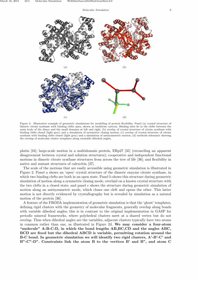
Figure 2. Illustrative example of geometric simulations for modelling of protein flexibility. Panel (a) crystal structure ofdimeric citrate synthase with binding clefts open, shown as backbone cartoon. Binding sites lie in the clefts between themain body of the dimer and the small domains at left and right; (b) overlay of crystal structure of citrate synthase withbinding clefts closed (light grey) and a simulation of symmetric closing motion; (c) overlay of crystal structure of citratesynthase with binding clefts closed (light grey) and a simulation of antisymmetric motion; (d) methods schematic showingthe overlap of molecular cluster templates along rotatable dihedral angles.
platin [34]; large-scale motion in a multidomain protein, ERp27 [35] (reconciling an apparentdisagreement between crystal and solution structures); cooperative and independent functionalmotions in dimeric citrate synthase structures from across the tree of life [36]; and flexibility innative and mutant structures of calexcitin [37].
The scale of the motions that are easily accessible using geometric simulation is illustrated inFigure 2. Panel a shows an ‘open’ crystal structure of the dimeric enzyme citrate synthase, inwhich two binding clefts are both in an open state. Panel b shows this structure during geometricsimulation of motion along a symmetric closing mode, overlaid on a known crystal structure withthe two clefts in a closed state; and panel c shows the structure during geometric simulation ofmotion along an antisymmetric mode, which closes one cleft and opens the other. This lattermotion is not directly evidenced by crystallography but is revealed by simulation as a naturalmotion of the protein [36].
A feature of the FRODA implementation of geometric simulation is that the ‘ghost’ templates,defining rigid clusters with the geometry of molecular fragments, generally overlap along bondswith variable dihedral angles; this is in contrast to the original implementation in GASP forperiodic mineral frameworks, where polyhedral clusters meet at a shared vertex but do notoverlap. Thus when dihedral angles are the variables, adjacent clusters typically have two atomsin common rather than one, as illustrated in Figure 2d. We may consider a four-atom“molecule” A-B-C-D, in which the bond lengths AB,BC,CD and the angles ABC,BCD are fixed but the dihedral ABCD is variable, permitting rotation around theB-C bond. In geometric simulation we will identify two rigid clusters, A’-B’-C’ andB”-C”-D”. Constraints link the atom B to the vertices B’ and B”, and atom C

March 16, 2015 22:5 Molecular Simulation WellsSartbaevaMolSimGeomSimv2.0
10 Wells and Sartbaeva
to vertices C’ and C”. As a result the cluster bonds B’-C’ and B”-C” will be keptparallel, but rotation around the B-C bond is permitted. Another difference from GASPis that the bonding geometry in FRODA is defined by the input structure rather than beinggenerated mathematically as regular polyhedra.
The latest version of GASP has a more general logic for the identification and handling ofclusters, and so is capable of modelling frameworks containing both polyhedral and molecular(overlapping) rigid clusters. It is this extension, making use of concepts developed in FRODA,that makes GASP v.5 suitable for the study of metal-organic frameworks.
4 The flexibility window in zeolites
Geometric simulation has been applied to investigate compression mechanisms in zeolites (section3.1), tetrahedral distortion in real and hypothetical zeolites and AlPOs [38], and to the detectionof unfeasible hypothetical zeolite frameworks [39] generated through Symmetry-ConstrainedIntersite Bonding Search (SCIBS) [40, 41]. This focus on zeolites led to a question: in a zeoliteframework, is it possible in principle for the tetrahedral geometry to be made ideal and perfect?Or are the small distortions typically seen in crystal structures in fact inevitable, given theframework topology and geometry?
Ideal tetrahedral geometry signifies that all Si–O distances are equal to the ideal bond length,e.g. 1.61A, and that all O–Si–O angles are equal to the tetrahedral angle arccos(−1/3), to withinsome defined precision. In a geometric simulation, this is equivalent to a requirement that themismatch between any atom and its corresponding vertex on a tetrahedral template be less thana defined threshold, which we set at 0.001A. The bridging Si–O–Si angles are left unconstrained.
The results of this investigation were unexpected and striking [12, 42, 43]. It emerges that,firstly, actually existing real (natural or synthetic) zeolites can indeed attain ideal geometry whenmodelled as silica in geometric simulations. Secondly, this can be done over a range of densities;limits arise on expansion from extension of Si–O bonds, and in compression from steric collisionsof oxygen atoms on adjacent tetrahedra (‘codimeric’ oxygens). This range we dub the ‘flexibilitywindow’. Thirdly, zeolites under ambient conditions are found to lie towards the low-density edgeof the window. From this point of view, zeolites can be viewed as a form of ‘expanded condensedmatter’ — the frameworks seek to be expanded as far as the framework topology will allow.
Figure 3 illustrates the use of geometric simulation to explore the flexibility window of theLTN zeolite framework. This structure is notable for its extremely large cubic unit cell (a =
35.62A) [11] containing 768 tetrahedra; however GASP rapidly relaxes the structure, with 2304independently mobile atoms. The investigation to determine the range of the flexibility windowas illustrated in Figure 3 took only a few minutes on a single processor. The initial inputis an all-atom representation of the structure in XTL format, essentially a unit cell and listof coordinates. Such all-atom inputs are easily generated from the fully symmetric structurein CIF format by export of coordinates in a structure viewer such as CrystalMaker [44]. Aninitial geometric relaxation using the cell parameter at ambient conditions rapidly idealises thetetrahedral geometry and confirms that the structure lies within its flexibility window. Therelaxed structure under these conditions is shown in Figure 3c,d. Progressively increasing thecubic a parameter, we soon find an upper limit to expansion, beyond which distortions areinevitable as bonds begin to be over-extended. For LTN this occurs when the unit cell volumehas increased by 2.5%. This condition is illustrated in Figure 3a,b; the similarity of the ambientand maximally-expanded cases is visually evident. Decreasing the a parameter, we find a muchgreater scope for compression, with the framework folding freely until arrested by collisions ofcodimeric oxygen atoms. Here this occurs when the unit cell volume has decreased by 14% andis illustrated in Figure 3e,f.
The majority of hypothetical zeolites, by contrast, are found to lack the ‘flexibility window’property [45] even if the framework is assigned a low energy by interatomic potential calcula-

March 16, 2015 22:5 Molecular Simulation WellsSartbaevaMolSimGeomSimv2.0
Molecular Simulation 11
(a) (b)
(c) (d)
(e) (f)
Figure 3. Application of geometric simulation to zeolite framework LTN. Panels show a single unit cell of the structurein tetrahedral (left) and space-filling (right) views. (a,b): structure at maximum geometric expansion; (c,d): structure withcell parameter found experimentally at ambient conditions; (e,f): structure at maximum geometric compression. Note thesimilarity of the ambient to the maximally expanded case.
tions. This suggests that the flexibility window is a key criterion in the selection of hypotheticalframeworks as candidates for synthesis [42]; structures lacking this property cannot be formedwithout causing strain in the building units, and so will be disfavoured relative to structures witha flexibility window. In recent years, GASP has been applied to assess new frameworkssubmitted to the Zeolite Structure Commission (Prof. M.M.J. Treacy, personal com-munication by email, 2015).

March 16, 2015 22:5 Molecular Simulation WellsSartbaevaMolSimGeomSimv2.0
12 Wells and Sartbaeva
The flexibility window concept also provides valuable insights in interpreting experimental dataon zeolites under compression. In zeolites of the analcime group, displaying phase transitionsfrom high to low symmetry forms when subjected to pressures of 1–2 GPa, the transition appearsto occur when the structure is compressed to the limit of the flexibility window [46–48]. Anintriguing finding is that structures displaying pressure-induced amorphisation at low pressuresdo so while the framework lies within its flexibility window. If the compression conditions movethe structure out of its flexibility window, e.g. through pore occupation by penetrating pressuremedia [49], the structure then resists amorphisation. From this point of view, the amorphisationof the framework is a process permitted by framework flexibility.
4.1 Extrinsic and intrinsic flexibility window
In a recent publication [50] we have further developed the concept of the flexibility windowby considering the effect of explicitly present extraframework content. The flexibility windowas originally defined may be termed ‘intrinsic’, being a property of the framework alone. The‘extrinsic’ window, in contrast, is affected by interactions between the framework and the ex-traframework content. This study was conducted based on a structural refinement of siliceousfaujasite by Colligan et. al. [51], in which it is noticeable that extraframework content nominallyrefined as ‘water oxygens’ lies in positions that are not in fact sterically possible, due to clasheswith the framework and/or other extraframework sites (see Figure 4a,b).
The compression experiments were carried out using a methanol/ethanol/water pressuremedium; we therefore considered cage occupation by various combinations of water and methanolmolecules. For this study, water molecules were represented as spheres while methanol was rep-resented as two spheres representing the methyl and hydroxy groups. Framework and contentgeometries generated during these simulations are shown in Figure 4b,c,d. Geometric relax-ation of the structure with water occupying all refined extra-framework sites, withboth framework and content atoms mobile, shifts the extra-framework water fromthe refined positions to a different, approximately close-packed arrangement, asshown in Figure 4b,c. The experimental extraframework electron density may bebetter accounted for if the cages are occupied by both water and methanol moleculesin a disordered arrangement, as in Figure 4d.
The limits of the flexibility window in compression behave more or less as expected. At zeroor low loadings we observe the framework-controlled limit of the intrinsic window. At higherloadings, the extrinsic window takes over, as framework/content interactions begin to limitthe degree of compression that the framework can achieve. An unexpected feature, however, isthe limitation of the extrinsic window on expansion. When the beta cages are heavily loaded(containing both methanol and water molecules), the maximum expansion the framework canachieve is less than the limit of the intrinsic window! The cages require a degree of internalflexibility to accomodate their bulky contents, and this internal flexibility is lacking at theexpanded edge of the intrinsic window.
5 Geometric simulation and flexibility in metal-organic frameworks
There is considerable current research interest in questions of rigidity and flexibility in MOFs[52]. If materials of this type are to attain their potential for industrial applications, designprinciples for control of their stability, rigidity and flexibility are a prerequisite. For this reason,the capacity to handle MOFs, ZIFs (zeolitic imidazolate frameworks) and similar frameworkswith non-polyhedral components is now included in version 5 of GASP. We will briefly reviewthe features needed to make MOFs tractable in GASP (section 5.1) and an illustrative casestudy (section 5.2).

March 16, 2015 22:5 Molecular Simulation WellsSartbaevaMolSimGeomSimv2.0
Molecular Simulation 13
(a) (b)
(c) (d)
Figure 4. Geometric simulations of framework flexibility with extraframework contents. Panel (a) framework tetrahedraand extraframework ‘water’ spheres in a beta cage of siliceous faujasite from a refined crystal structure [51]; (b) geometricallyrelaxed framework and contents, showing substantial rearrangements to resolve steric clashes; (c) geometrically relaxedframework and contents, with framework oxygens in space-filling view. One of the framework 6-ring aper-tures has been removed from the view to allow the contents to be seen ; (d) cage occupation by a combinationof water and methanol molecules. Figures are from the authors’ work in reference [50].
5.1 Geometry and rigidity of non-polyhedral framework units
The geometry of polyhedral units is communicated to GASP by specifying a polyhedral shape,e.g. ‘tet’ for tetrahedron, the identity of the centre and vertex species, e.g. ‘Si O’, and an idealbond length, e.g. ‘1.61’ (A). Non-polyhedral molecular units are now specified by a series of lines,each identifying a ‘central’ atom species, e.g. ‘C’, followed by all species to which it may bond.Terminal (singly-bonded) species need not be specified explicitly. Thus for example the bondingin a typical small organic molecule might be specified by the lines ‘C C H N O’, ‘N C H’, and‘O C H’. With this information, GASP will identify a series of overlapping bonded groups eachconsisting of a ‘central’ atom and its bonded neighbours. The geometry of each such cluster,as found in the input structure, will then be maintained in subsequent geometric simulations.An atom can simultaneously be a vertex species in a polyhedral group and part of a moleculargroup — for example the metal-coordinating carboxylate oxygens found in many MOFs.
If no further processing took place, all dihedral angles in molecular framework componentswould be variable. However, in general, the linkers in MOFs show considerable rigidity due todelocalised bonding extending over adjacent sp2 hybridised atoms. GASP therefore carries outa further phase of cluster unification if desired. sp2 hybridised carbon and nitrogen atomsare recognised by their trigonal bonding, and adjacent cases are unified into a single cluster,

March 16, 2015 22:5 Molecular Simulation WellsSartbaevaMolSimGeomSimv2.0
14 Wells and Sartbaeva
thus rigidifying the molecule appropriately. Cluster rigidity can be fully controlled by theuser on a bond-by-bond basis when required: the bonding topology can be exportedfrom GASP in a simple text format and edited to label specific bonds as rotatable orlocked. Non-sp2 rigidity arising from overconstraint, as for example in adamantanes,arises naturally from the overlap of rigid clusters in GASP.
Sensible steric radii must also be assigned to the atoms present in the structure.This is to some extent a question of judgement, and detailed results — especiallyon the limits in compression of the flexibility window — will depend on the valueschosen. The radii assigned should therefore be reported explicitly when the resultsare affected by steric contacts within the framework. In the study below (5.2) theresults depend only on the bonding geometry; for completeness we note that theradii assigned were C=1.70, H=1.0,Cr=0.6,O=1.35A.
Flexibility in the structure can then be explored by specifying new cell parameters for thesystem; GASP will impose these new parameters but maintain the bonding geometry of clustersspecified in the original input. Geometric relaxation will determine how the framework respondsto the strain, within the geometric simulation model, and whether the molecular clusters canmaintain their shape or must be distorted. In the general case, a flexibility window isa six-dimensional hypershape, as the cell parameters a, b, c, α, β, γ can all be variedindependently. An exploration within a particular crystal system is generally moreconstrained; a cubic system has only a single relevant parameter, a hexagonal systemtwo.
With these new capabilities in GASP version 5, the concept of the ‘flexibility window’ cannow be generalised from zeolites to MOFs, ZIFs and flexible frameworks in general.
5.2 Case study: rigidity and strain in MIL-47 and MIL-53
The MIL-47 / MIL53 system provides an interesting first test case. These materials are metaldicarboxylate MOFs with very similar structures, distinguished by the oxidation state of themetal ion and the consequent presence or absence of a bridging hydroxy group in the frame-work. In this case, two frameworks with essentially identical topology display strikingly differentflexibility behaviour: rigidity in one case [53], flexible compliance in the other, with the structurefolding by a ‘wine-rack’ mechanism [54]. We have therefore examined a vanadium MIL-47 and achromium MIL-53 framework using GASP version 5. The goal of this pilot study is, firstly, to seewhat insights geometric analysis and simulation can produce into the rigidity of the framework,and secondly, to determine whether geometric simulation can produce the wine-rack mechanismas a stress-free motion of the framework.
Considering first the crystal structure of MIL-47 [55], we note that the coordination of themetal (vanadium) centre by oxygens is sixfold but shows substantial deviations from regularoctahedral geometry. Indeed, the metal ion appears to lie off the plane formed by four coordi-nating carboxylate oxygens, being much closer to one of the bridging oxygens than to the other,as shown in Figure 5a, due to the formation of the [VO]2+ vanadyl unit. This immediatelyraises the question of whether regular octahedral geometry around the metal centre is in factpossible. Investigating with GASP using a polyhedral specification of ‘oct v o 1.97’ — the bondlength being chosen from the average of the bonds observed in the crystal structure — we findthat at the cell parameters given, the distortion of octahedra cannot be reduced below 0.060A(for comparison, the input crystal structure displays a distortion of 0.174A). The geometry ofthe octahedra after relaxation is showin in Figure 5b.
Consideration of the connections between any two adjacent metal centres in the a directionmakes clear the origin of the distortion. Adjacent metal ions are linked through one bridgingoxygen and through two carboxylate groups, defining a very restrictive bonding geometry. Anincompatibility between the bond lengths in the MO6 octehedra, the O–C–O carboxylate group,and the spacing between adjacent metal centres (set by the a cell parameter), leads to distortions.

March 16, 2015 22:5 Molecular Simulation WellsSartbaevaMolSimGeomSimv2.0
REFERENCES 15
The distortions could be reduced further by adjustments of the a parameter and the V–O bondlength; for example, with the given octahedral geometry, a slight expansion of the a parameterfrom 13.64 to 14.05A reduces the bonding distortion in the framework to a mere 0.0025A.
In the MIL-53 framework, the bridging oxygen between adjacent metal centres is convertedto a bridging hydroxyl, reflecting the different oxidation states of the V and Cr ions in theframeworks. The Cr metal centre is found in square planar coordination by four carboxylateoxygens, with the hydroxy groups making up an ‘octahedron’; the Cr–OH bond differs from theCr–Ocarboxylate bond, at 1.90 versus 1.97A. This can be represented in GASP by specifying asquare-planar Cr:Ocarboxylate,4 geometry and a Cr:OH ‘bar’ geometry. Thus the bond lengths areall constrained, but the OH–Cr–Ocarboxylate angle is permitted to vary. Analysis of the inputcrystal structure using these settings reports a small distortion in the square planar units of0.032A; geometric relaxation reduces this distortion to less than 0.001A, effectively zero. Thusif we take the view that the change from a bridging oxygen to a bridging hydroxyl group acts toreduce constraints on the bonding geometry around the metal centre, we find that the MIL-47framework contains intrinsic stresses but the MIL-53 framework can be geometrically relaxed.
To investigate flexibility and the capacity for large-scale motion in MIL-53, we make use ofthe ‘new cell . . . ’ feature to vary the unit cell of the framework and observe the response of theframework. GASP seeks to maintain the geometry around the metal centres (square planar Cr–O+ bars Cr–OH) and the molecular geometry of the dicarboxylate linkers. To investigate “winerack” motion we consider variations in the b and c parameters. An initial test shows that neitherparameter can be varied on its own without the immediate onset of unresolvable distortionsin the framework due to incompatible bonding geometry. However, a variation in which b isincreased and c reduced in appropriate ratio does generate a stress-free motion in which theframework folds as expected. This is illustrated in Figure 5c, showing the crystal structure ofMIL-53 with pores open, and in Figure 5d, in which the b, c parameters have been substantiallyaltered from their initial values (b = 16.73 and c = 13.04A) to b = 18.40, c = 10.00A. Here c wasset arbitrarily and we searched for a value of b that allows the framework geometry to remainundistorted.
The results reported here are simply a pilot study demonstrating the applicabilityof GASP to the study of MOFs. Detailed results will depend on subtle interactionsbetween the local bonding geometry around metal sites (polyhedral shapes, bondlengths), the steric geometry (atomic radii) assigned to the atoms, and the globalgeometry of the framework (unit cell parameters). Elucidating these interactionswill be highly productive of insights for the design and understanding of MOFs.We anticipate that the investigation of rigidity and flexibility of MOFs using GASPwill be a rich seam for future study. Of particular interest will be the comparisonof results from the real-space approach of GASP and reciprocal-space approaches,such as those recently applied to MOFs by Rimmer et. al.[56]; and the comparisonto other framework flexibility approaches such as the bar and hinge approach ofSarkisov et. al.[57].
Acknowledgements
AS thanks the Royal Society for fellowship funding. SAW acknowledges funding from EPSRCproject grant EP/K004956/1.
References
[1] D.S. Wragg, R.S. Morris, and A.W. Burton, Pure Silica Zeolite-type Frameworks: a structural analysis, Chemistry ofMaterials 20 (2008), pp. 1561–1570.
[2] W.H. Baur, Straight Si–O–Si Bridging Bonds Do Exist in Silicates and Silicon Dioxide Polymorphs, Acta Crystallo-graphica B 36 (1980), pp. 2198–2202.

March 16, 2015 22:5 Molecular Simulation WellsSartbaevaMolSimGeomSimv2.0
16 REFERENCES
(a) (b)
(c) (d)
Figure 5. Investigation of rigidity and flexibility in MOFs. Panel (a) adjacent VO6 octahedra in MIL-47 linked by a bridgingoxygen vertex and two carbonyl groups, showing the apparent distortion from octahedral geometry in the crystal structure;(b) the same octahedra after geometric relaxation of the framework, showing almost regular geometry; (c) view down thechannels of MIL-53; (d) simulation of ‘wine rack’ motion in MIL-53.
[3] S.A. Wells, M.T. Dove, and M.G. Tucker, Finding best-fit polyhedral rotations with geometric algebra, Journal ofPhysics: Condensed Matter 14 (2002), pp. 4567–4584.
[4] S.A. Wells, M.T. Dove, M.G. Tucker, and K. Trachenko, Real-space rigid-unit-mode analysis of dynamic disorder inquartz, cristobalite and amorphous silica, Journal of Physics: Condensed Matter 14 (2002), p. 4645.
[5] M.T. Dove, M.G. Tucker, and D.A. Keen, Neutron total scattering method: simultaneous determination of long-rangeand short-range order in disordered materials, European Journal of Mineralogy 14 (2002), pp. 331–348.
[6] S.A. Wells, M.T. Dove, and M.G. Tucker, Reverse Monte Carlo with geometric analysis – RMC+GA, Journal ofApplied Crystallography 37 (2004), pp. 536–544.
[7] D.A. Keen, M.G. Tucker, and M.T. Dove, Reverse Monte Carlo modelling of crystalline disorder, Journal of Physics:Condensed Matter 17 (2005), pp. S15–S22.
[8] S.A. Wells and A. Sartbaeva, Template-Based Geometric Simulation of Flexible Frameworks, Materials 5 (2012), pp.415–431 http://www.mdpi.com/1996-1944/5/3/415.
[9] J.D. Gale, GULP: A computer program for the symmetry-adapted simulation of solids, Journal of the Chemical Society,Faraday Transactions 93 (1995), pp. 629–637.
[10] S.G.A. Lasenby and C. Doran, Imaginary numbers are not real: The geometric algebra of spacetime, Foundations ofPhysics 23 (1993), pp. 1175–1201 http://dx.doi.org/10.1007/BF01883676.
[11] C. Baerlocher, W. Meier, and D. Olson, Atlas of Zeolite Framework Types Elsevier, Amsterdam, 2001.[12] A. Sartbaeva, S.A. Wells, M.M.J. Treacy, and M.F. Thorpe, The flexibility window in zeolites, Nature Materials 5
(2006), pp. 962–965.[13] M.T. Dove, V. Heine, and K.D. Hammonds, Rigid unit modes in framework silicates, Mineralogical Magazine 59 (1995),
pp. 629–639.[14] M.T. Dove, A.K.A. Pryde, and V. Heine, Exotic distributions of rigid unit modes in the reciprocal spaces of framework
aluminosilicates, Journal of Physics: Condensed Matter 19 (2007), p. 275209.[15] A.L. Goodwin, The crystallography of flexibility: Local structure and dynamics in framework materials, Zeitschrift Fur
Kristallographie 30 (2009), pp. 1–11.[16] A.L. Goodwin, S.A. Wells, and M.T. Dove, Cation substitution and strain screening in framework structures: The role
of rigid unit modes, Chemical Geology 225 (2006), pp. 213–221.[17] A. Sartbaeva, S.A.T. Redfern, and W.T. Lee, A neutron diffraction and Rietveld analysis of cooperative Li motion in
beta-eucryptite, Journal of Physics: Condensed Matter 16 (2004), pp. 5267–5278.[18] A. Sartbaeva, S.A. Wells, and S.A.T. Redfern, Li+ ion motion in quartz and β-eucryptite studied by dielectric spec-
troscopy and atomistic simulations, Journal of Physics: Condensed Matter 16 (2004), pp. 8173–8189.[19] A. Sartbaeva, S.A. Wells, S.A.T. Redfern, R.W. Hinton, and S.J.B. Reed, Ionic diffusion in quartz studied by transport
measurements, SIMS and atomistic simulations, Journal of Physics: Condensed Matter 17 (2005), pp. 1099–1112.[20] G.D. Gatta and S.A. Wells, Rigid unit modes at high pressure: an explorative study of a fibrous zeolite-like framework
with EDI topology, Physics and Chemistry of Minerals 31 (2004), pp. 465–474.[21] G.D. Gatta and S.A. Wells, Structural evolution of zeolite levyne under hydrostatic and non-hydrostatic pressure:
geometric modelling, Physics and Chemistry of Minerals 33 (2006), pp. 243–255.[22] A.L. Goodwin, S.A.T. Redfern, M.T. Dove, D.A. Keen, and M.G. Tucker, Ferroelectric nanoscale domains and the

March 16, 2015 22:5 Molecular Simulation WellsSartbaevaMolSimGeomSimv2.0
REFERENCES 17
905K phase transition in SrSnO3: A neutron total-scattering study, Physical Review B 76 (2007), p. 174114.[23] Q. Hui, M.G. Tucker, M.T. Dove, S.A. Wells, and D.A. Keen, Total scattering and reverse Monte Carlo study of the
105K displacive phase transition in strontium titanate, Journal of Physics: Condensed Matter 17 (2005), pp. S111–S124.[24] A. Sartbaeva, S.A. Wells, M.F. Thorpe, E.S. Bozin, and S.J.L. Billinge, Geometric Simulation of Perovskite Frameworks
with Jahn-Teller Distortions: Applications to the Cubic Manganites, Physical Review Letters 97 (2006), p. 065501.[25] A. Sartbaeva, S.A. Wells, M.F. Thorpe, E.S. Bozin, and S.J.L. Billinge, Quadrupolar Ordering in LaMnO3 Revealed
from Scattering Data and Geometric Modellings, Physical Review Letters 99 (2007), p. 155503.[26] M.G. Tucker, A.L. Goodwin, M.T. Dove, D.A. Keen, S.A. Wells, and J.S.O. Evans, Negative Thermal Expansion in
ZrW2O8: Mechanisms, Rigid Unit Modes, and Neutron Total Scattering, Physical Review Letters 95 (2005), p. 255501.[27] M.J. Conterio, A.L. Goodwin, M.G. Tucker, D.A. Keen, M.T. Dove, L. Peters, and S.O. Evans, Local structure in
Ag3[Co(CN)6]: colossal thermal expansion, rigid unit modes and argentophilic interactions, Journal of Physics: Con-densed Matter 20 (2008), p. 255225.
[28] S.A. Wells, S. Menor, B.M. Hespenheide, and M.F. Thorpe, Constrained geometric simulation of diffusive motion inproteins, Physical Biology 2 (2005), pp. S127–S136.
[29] D.J. Jacobs, A.J. Rader, L.A. Kuhn, and M.F. Thorpe, Protein flexibility predictions using graph theory, Proteins:Structure, Function and Bioinformatics 44 (2001), pp. 150–165.
[30] D.W. Farrell, K. Speranskiy, and M.F. Thorpe, Generating stereochemically acceptable protein pathways, Proteins:Structure, Function and Bioinformatics 78 (2010), pp. 2908–2921.
[31] A. Ahmed, F. Rippmann, G. Barnickel, and H. Gohlke, A normal mode-based geometric simulation approach forexploring biologically relevant conformational transitions in proteins, Journal of Chemical Informatics and Modelling51 (2011), pp. 1604–1622.
[32] J.E. Jimenez-Roldan, R.B. Freedman, R.A. Romer, and S.A. Wells, Rapid simulation of protein motion: mergingflexibility, rigidity and normal mode analyses, Physical Biology 9 (2012), p. 016008.
[33] N.S. Burkoff, C. Varnai, D.L. Wild, and S.A. Wells, Exploring the energy landscapes of protein folding simulationswith Bayesian computation, Biophysical Journal 102 (2012), pp. 878–886.
[34] H. Li, S.A. Wells, J.E. Jimenez-Roldan, R.A. Romer, Y. Zhao, P.J. Sadler, and P.B. O’Connor, Protein flexibility iskey to cisplatin crosslinking in calmodulin, Protein Science 21 (2012), pp. 1269–1279.
[35] N.T. Amin, A.K. Wallis, S.A. Wells, M.L. Rowe, R.A. Williamson, M.J. Howard, and R.B. Freedman, High-resolutionNMR studies of structure and dynamics of human ERp27 indicate extensive inter-domain flexibility, BiochemicalJournal 450 (2013), pp. 321–332.
[36] S.A. Wells, S.J. Crennell, and M.J. Danson, Structures of mesophilic and extremophilic citrate synthases reveal rigidityand flexibility for function, Proteins: Structure, Function, and Bioinformatics 82 (2014), pp. 2657–2670.
[37] P. Erskine, A. Fokas, C. Muriithi, H. Rehman, L. Yates, A. Bowyer, S. Findlow, R. Hagan, J. Werner, A. Miles,S.A. Wells, S. Wood, and J. Cooper, X-ray, spectroscopic and normal-mode dynamics of calexcitin: structure-functionstudies of a neuronal calcium-signalling protein, Acta Crystallographica D (2015) (In press).
[38] M.A. Zwijnenburg, A. Simperler, S.A. Wells, and R.G. Bell, Tetrahedral distortion and energetic packing penalty in“zeolite” frameworks: linked phenomena, Journal of Physical Chemistry B 109 (2005), pp. 14783–14785.
[39] S.A. Wells, M.D. Foster, and M.M.J. Treacy, A simple geometric structure optimizer for accelerated detection ofinfeasible zeolite graphs, Microporous and Mesoporous Materials 93 (2007), pp. 151–157.
[40] M.M.J. Treacy, K.H. Randall, S. Rao, J.A. Perry, and D.J. Chadi, Enumeration of Periodic Tetrahedral Frameworks,Zeitschrift Fur Kristallographie 212 (1997), pp. 768–791.
[41] M.M.J. Treacy, I. Rivin, E. Balkovsky, K.H. Randall, and M.D. Foster, Enumeration of Periodic Tetrahedral Frame-works II. Polynodal graphs, Microporous and Mesoporous Materials 74 (2004), pp. 121–132.
[42] I. Rivin, Geometric simulations: A lesson from virtual zeolites, Nature Materials 5 (2006), pp. 931–932.[43] V. Kapko, C. Dawson, and M.M.J. Treacy, Flexibility of ideal zeolite frameworks, Physical Chemistry Chemical Physics
12 (2010), pp. 8531–8541.[44] CrystalMaker; software available from CrystalMaker Software Limited at http://www.crystalmaker.com/index.html.[45] V. Kapko, C. Dawson, I. Rivin, and M.M.J. Treacy, Density of Mechanisms within the Flexibility Window of Zeolites,
Physical Review Letters 107 (2011), p. 164304.[46] A. Sartbaeva, G.D. Gatta, and S.A. Wells, Flexibility window controls pressure-induced phase transition in analcime,
Europhysics Letters 83 (2008), p. 26002.[47] G.D. Gatta, A. Sartbaeva, and S.A. Wells, Compression behaviour and flexibility window of the analcime-like
feldspathoids: experimental and theoretical findings, European Journal of Mineralogy 21 (2009), pp. 571–580.[48] S.A. Wells, A. Sartbaeva, and G.D. Gatta, Flexibility windows and phase transitions of ordered and disordered ANA
framework zeolites, Europhysics Letters 94 (2011), p. 56001.[49] A. Sartbaeva, J. Haines, O. Cambon, M. Santoro, F. Gorelli, C. Levelut, G. Garbarino, and S.A. Wells, Flexibility
windows and compression of monoclinic and orthorombic silicalites, Physical Review B 85 (2012), p. 064109.[50] S.A. Wells, K.M. Leung, P.P. Edwards, and A. Sartbaeva, Flexibility windows in faujasite with explicit water and
methanol extra-framework content, Dalton Transactions (2014) Advance online. DOI: 10.1039/C4DT03150D.[51] M. Colligan, P.M. Forster, A.K. Cheetham, Y. Lee, T. Vogt, and J.A. Hriljac, Synchrotron X-ray Powder Diffraction
and Computational Investigation of Purely Siliceous Zeolite Y under Pressure, Journal of the American ChemicalSociety 126 (2004), pp. 12015–12022.
[52] W. Li, S. Henke, and A.K. Cheetham, Mechanical properties of metal-organic frameworks — influence of structureand chemical bonding, APL Materials 2 (2014), p. 123902.
[53] D.I. Kolokolov, H. Jobic, A.G. Stepanov, M. Plazanet, M. Zbiri, J. Ollivier, V. Guillerm, T. Devic, C. Serre, and G.Ferey, Comparison of the dynamics of MIL-53(Cr) and MIL-47(V) frameworks using neutron scattering and DFTmethods, Eur. Phys. J. Special Topics 189 (2010), pp. 263–271.
[54] L. Chen, J.P.S. Mowat, D. Fairen-Jimenez, C.A. Morrison, S.P. Thompson, P.A. Wright, and T. Duren, Elucidating theBreathing of the MetalOrganic Framework MIL-53(Sc) with ab Initio Molecular Dynamics Simulations and in SituX-ray Powder Diffraction Experiments, J. Am. Chem. Soc 135 (2013), pp. 15763–15773.
[55] K. Barthelet, J. Marrot, D. Riou, and G. Ferey, A Breathing Hybrid Organic-Inorganic Solid with Very Large Poresand High Magnetic Characteristics, Angew. Chem. 114 (2002), pp. 291–294.
[56] L.H.N. Rimmer, M.T. Dove, A.L. Goodwin, and D.C. Palmer, Acoustic phonons and negative thermal expansion inMOF-5, Phys. Chem. Chem. Phys. 16 (2014), pp. 21144–21152.
[57] L. Sarkisov, R.L. Martin, M. Haranczyk, and B. Smit, On the Flexibility of Metal?Organic Frameworks, J. Am. Chem.

March 16, 2015 22:5 Molecular Simulation WellsSartbaevaMolSimGeomSimv2.0
18 REFERENCES
Soc. 136 (2014), pp. 2228–2231.