Embed Size (px)
Citation preview

OPTOCONTROLCOMMAND REFERENCE
Form 725-120508—May, 2012
43044 Business Park Drive • Temecula • CA 92590-3614Phone: 800-321-OPTO (6786) or 951-695-3000
Fax: 800-832-OPTO (6786) or 951-695-2712www.opto22.com
Product Support Services800-TEK-OPTO (835-6786) or 951-695-3080
Fax: 951-695-3017Email: [email protected]
Web: support.opto22.com

OptoControl Command Reference Form 725-120508—May, 2012
Copyright © 1998–2012 Opto 22.All rights reserved.Printed in the United States of America.
The information in this manual has been checked carefully and is believed to be accurate; however, Opto 22 assumes no responsibility for possible inaccuracies or omissions. Specifications are subject to change without notice.
Opto 22 warrants all of its products to be free from defects in material or workmanship for 30 months from the manufacturing date code. This warranty is limited to the original cost of the unit only and does not cover installation, labor, or any other contingent costs. Opto 22 I/O modules and solid-state relays with date codes of 1/96 or later are guaranteed for life. This lifetime warranty excludes reed relay, SNAP serial communication modules, SNAP PID modules, and modules that contain mechanical contacts or switches. Opto 22 does not warrant any product, components, or parts not manufactured by Opto 22; for these items, the warranty from the original manufacturer applies. These products include, but are not limited to, OptoTerminal-G70, OptoTerminal-G75, and Sony Ericsson GT-48; see the product data sheet for specific warranty information. Refer to Opto 22 form number 1042 for complete warranty information.
Wired+Wireless controllers and brains and N-TRON wireless access points are licensed under one or more of the following patents: U.S. Patent No(s). 5282222, RE37802, 6963617; Canadian Patent No. 2064975; European Patent No. 1142245; French Patent No. 1142245; British Patent No. 1142245; Japanese Patent No. 2002535925A; German Patent No. 60011224.
Opto 22 FactoryFloor, Optomux, and Pamux are registered trademarks of Opto 22. Generation 4, ioControl, ioDisplay, ioManager, ioProject, ioUtilities, mistic, Nvio, Nvio.net Web Portal, OptoConnect, OptoControl, OptoDataLink, OptoDisplay, OptoEMU, OptoEMU Sensor, OptoEMU Server, OptoOPCServer, OptoScript, OptoServer, OptoTerminal, OptoUtilities, PAC Control, PAC Display, PAC Manager, PAC Project, SNAP Ethernet I/O, SNAP I/O, SNAP OEM I/O, SNAP PAC System, SNAP Simple I/O, SNAP Ultimate I/O, and Wired+Wireless are trademarks of Opto 22.
ActiveX, JScript, Microsoft, MS-DOS, VBScript, Visual Basic, Visual C++, Windows, and Windows Vista are either registered trademarks or trademarks of Microsoft Corporation in the United States and other countries. Linux is a registered trademark of Linus Torvalds. Unicenter is a registered trademark of Computer Associates International, Inc. ARCNET is a registered trademark of Datapoint Corporation. Modbus is a registered trademark of Schneider Electric. Wiegand is a registered trademark of Sensor Engineering Corporation. Nokia, Nokia M2M Platform, Nokia M2M Gateway Software, and Nokia 31 GSM Connectivity Terminal are trademarks or registered trademarks of Nokia Corporation. Sony is a trademark of Sony Corporation. Ericsson is a trademark of Telefonaktiebolaget LM Ericsson. CompactLogix, MicroLogix, SLC, and RSLogix are trademarks of Rockwell Automation. Allen-Bradley and ControlLogix are a registered trademarks of Rockwell Automation. CIP and EtherNet/IP are trademarks of ODVA.
All other brand or product names are trademarks or registered trademarks of their respective companies or organizations.
OptoControl Command Referenceii
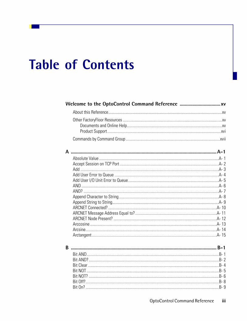
Table of Contents
Welcome to the OptoControl Command Reference ................................ xv
About this Reference..............................................................................................................xv
Other FactoryFloor Resources ................................................................................................xvDocuments and Online Help............................................................................................xvProduct Support..............................................................................................................xvi
Commands by Command Group ...........................................................................................xvii
A ................................................................................................................... A-1Absolute Value ....................................................................................................................A- 1Accept Session on TCP Port ................................................................................................A- 2Add ......................................................................................................................................A- 3Add User Error to Queue .....................................................................................................A- 4Add User I/O Unit Error to Queue........................................................................................A- 5AND .....................................................................................................................................A- 6AND? ...................................................................................................................................A- 7Append Character to String.................................................................................................A- 8Append String to String.......................................................................................................A- 9ARCNET Connected? .........................................................................................................A- 10ARCNET Message Address Equal to?...............................................................................A- 11ARCNET Node Present? ....................................................................................................A- 12Arccosine ...........................................................................................................................A- 13Arcsine...............................................................................................................................A- 14Arctangent .........................................................................................................................A- 15
B ................................................................................................................... B-1Bit AND................................................................................................................................B- 1Bit AND?..............................................................................................................................B- 2Bit Clear ...............................................................................................................................B- 4Bit NOT ................................................................................................................................B- 5Bit NOT? ..............................................................................................................................B- 6Bit Off?.................................................................................................................................B- 8Bit On? .................................................................................................................................B- 9
OptoControl Command Reference iii

Bit OR.................................................................................................................................B- 10Bit OR? ...............................................................................................................................B- 11Bit Rotate...........................................................................................................................B- 12Bit Set ................................................................................................................................B- 14Bit Shift..............................................................................................................................B- 15Bit Test ..............................................................................................................................B- 17Bit XOR ..............................................................................................................................B- 18Bit XOR?.............................................................................................................................B- 19
C ................................................................................................................... C-1Calculate & Set Analog Gain ..............................................................................................C- 1Calculate & Set Analog Offset ............................................................................................C- 3Calculate & Store Strategy CRC..........................................................................................C- 4Calculate Strategy CRC .......................................................................................................C- 5Call Chart .............................................................................................................................C- 6Calling Chart Running? ........................................................................................................C- 7Calling Chart Stopped?........................................................................................................C- 8Calling Chart Suspended? ...................................................................................................C- 9Caused a Chart Error?........................................................................................................C- 10Caused an I/O Unit Error?..................................................................................................C- 11Characters Waiting at Serial Port? ...................................................................................C- 12Chart Running? ..................................................................................................................C- 13Chart Stopped? ..................................................................................................................C- 14Chart Suspended? .............................................................................................................C- 15Clamp Float Table Element ...............................................................................................C- 16Clamp Float Variable .........................................................................................................C- 17Clamp Integer 32 Table Element .......................................................................................C- 18Clamp Integer 32 Variable.................................................................................................C- 19Clamp PID Output ..............................................................................................................C- 20Clamp PID Setpoint ...........................................................................................................C- 21Clear All Errors ..................................................................................................................C- 22Clear All Event Latches .....................................................................................................C- 23Clear All Latches ...............................................................................................................C- 24Clear Counter.....................................................................................................................C- 25Clear Event Latch...............................................................................................................C- 26Clear I/O Unit Interrupt......................................................................................................C- 27Clear Off-Latch ..................................................................................................................C- 28Clear On-Latch ...................................................................................................................C- 29Clear PC Byte Swap Mode (ISA only)................................................................................C- 30Clear Pointer ......................................................................................................................C- 30Clear Pointer Table Element..............................................................................................C- 31Clear Quadrature Counter .................................................................................................C- 32Clear Receive Buffer..........................................................................................................C- 33Close Ethernet Session .....................................................................................................C- 34Comment (Block)................................................................................................................C- 35Comment (Single Line) ......................................................................................................C- 36Communication to All I/O Points Enabled? .......................................................................C- 37
iv OptoControl Command Reference

Communication to All I/O Units Enabled?.........................................................................C- 38Complement ......................................................................................................................C- 39Configure I/O Unit .............................................................................................................C- 40Configure Port....................................................................................................................C- 41Configure Port Timeout Delay ...........................................................................................C- 42Continue Calling Chart ......................................................................................................C- 43Continue Chart...................................................................................................................C- 44Continue Timer ..................................................................................................................C- 45Convert Float to String ......................................................................................................C- 45Convert Hex String to Number ..........................................................................................C- 47Convert IEEE Hex String to Number ..................................................................................C- 48Convert Mistic I/O Hex to Float.........................................................................................C- 49Convert Number to Formatted Hex String.........................................................................C- 50Convert Number to Hex String ..........................................................................................C- 51Convert Number to Mistic I/O Hex....................................................................................C- 52Convert Number to String .................................................................................................C- 53Convert Number to String Field.........................................................................................C- 54Convert String to Float ......................................................................................................C- 55Convert String to Integer 32..............................................................................................C- 56Convert String to Integer 64..............................................................................................C- 57Convert String to Lower Case ...........................................................................................C- 59Convert String to Upper Case............................................................................................C- 59Copy Date to String (DD/MM/YY).....................................................................................C- 60Copy Date to String (MM/DD/YY).....................................................................................C- 61Copy Time to String ...........................................................................................................C- 62Cosine ................................................................................................................................C- 63CTS Off?.............................................................................................................................C- 64CTS On? .............................................................................................................................C- 65
D ................................................................................................................... D-1Decrement Variable.............................................................................................................D- 1Delay (mSec)........................................................................................................................D- 2Delay (Sec)...........................................................................................................................D- 3Disable Communication to All I/O Points............................................................................D- 4Disable Communication to All I/O Units .............................................................................D- 5Disable Communication to Analog Point ............................................................................D- 6Disable Communication to Digital Point .............................................................................D- 7Disable Communication to Event/Reaction ........................................................................D- 8Disable Communication to I/O Unit ....................................................................................D- 9Disable Communication to PID Loop.................................................................................D- 11Disable Event/Reaction Group ..........................................................................................D- 12Disable I/O Unit Causing Current Error .............................................................................D- 13Disable Interrupt on Event.................................................................................................D- 14Disable PID Output ............................................................................................................D- 15Disable PID Output Tracking in Manual Mode .................................................................D- 16Disable PID Setpoint Tracking in Manual Mode...............................................................D- 17Disable Scanning for All Events ........................................................................................D- 18
OptoControl Command Reference v

Disable Scanning for Event .............................................................................................. D- 19Disable Scanning of Event/Reaction Group ..................................................................... D- 20Divide................................................................................................................................ D- 21Down Timer Expired? ....................................................................................................... D- 22
E ....................................................................................................................E-1Enable Communication to All I/O Points .............................................................................E- 1Enable Communication to All I/O Units ..............................................................................E- 2Enable Communication to Analog Point..............................................................................E- 3Enable Communication to Digital Point ..............................................................................E- 4Enable Communication to Event/Reaction..........................................................................E- 5Enable Communication to I/O Unit......................................................................................E- 6Enable Communication to PID Loop ....................................................................................E- 7Enable Event/Reaction Group .............................................................................................E- 8Enable I/O Unit Causing Current Error ................................................................................E- 9Enable Interrupt on Event ..................................................................................................E- 10Enable PID Output .............................................................................................................E- 11Enable PID Output Tracking in Manual Mode...................................................................E- 12Enable PID Setpoint Tracking in Manual Mode................................................................E- 13Enable Scanning for All Events .........................................................................................E- 14Enable Scanning for Event ................................................................................................E- 15Enable Scanning of Event/Reaction Group .......................................................................E- 16Equal? ................................................................................................................................E- 16Equal to Table Element?....................................................................................................E- 18Error? .................................................................................................................................E- 19Error on I/O Unit?...............................................................................................................E- 20Ethernet Session Open? ....................................................................................................E- 21Event Occurred?.................................................................................................................E- 22Event Occurring?................................................................................................................E- 23Event/Reaction Communication Enabled? ........................................................................E- 24Event/Reaction Group Communication Enabled? .............................................................E- 25Event Scanning Disabled? .................................................................................................E- 26Event Scanning Enabled? ..................................................................................................E- 27
F ....................................................................................................................F-1Find Character in String....................................................................................................... F- 1Find Substring in String ....................................................................................................... F- 2Float Valid? .......................................................................................................................... F- 3
G ................................................................................................................... G-1Generate Checksum on String............................................................................................ G- 1Generate Forward CCITT on String .................................................................................... G- 2Generate Forward CRC-16 on String .................................................................................. G- 3Generate N Pulses.............................................................................................................. G- 4Generate Random Number................................................................................................. G- 5Generate Reverse CCITT on String..................................................................................... G- 6
vi OptoControl Command Reference

Generate Reverse CRC-16 on String ...................................................................................G- 7Generate Reverse CRC-16 on Table (32 bit)........................................................................G- 8Generating Interrupt? ..........................................................................................................G- 9Get & Clear Analog Filtered Value....................................................................................G- 10Get & Clear Analog Maximum Value................................................................................G- 11Get & Clear Analog Minimum Value.................................................................................G- 12Get & Clear Analog Totalizer Value ..................................................................................G- 13Get & Clear Counter ..........................................................................................................G- 14Get & Clear Digital I/O Unit Latches.................................................................................G- 15Get & Clear Digital-64 I/O Unit Latches............................................................................G- 16Get & Clear Event Latches ................................................................................................G- 18Get & Clear Off-Latch........................................................................................................G- 19Get & Clear On-Latch ........................................................................................................G- 20Get & Clear Quadrature Counter .......................................................................................G- 21Get & Clear Simple-64 I/O Unit Latches ...........................................................................G- 22Get & Restart Off-Pulse Measurement.............................................................................G- 23Get & Restart Off-Time Totalizer ......................................................................................G- 24Get & Restart On-Pulse Measurement .............................................................................G- 25Get & Restart On-Time Totalizer .......................................................................................G- 26Get & Restart Period .........................................................................................................G- 27Get Active Interrupt Mask.................................................................................................G- 28Get Address of I/O Unit Causing Current Error .................................................................G- 29Get Analog Filtered Value .................................................................................................G- 30Get Analog Lower Clamp ..................................................................................................G- 31Get Analog Maximum Value .............................................................................................G- 32Get Analog Minimum Value..............................................................................................G- 33Get Analog Square Root Filtered Value ............................................................................G- 34Get Analog Square Root Value .........................................................................................G- 35Get Analog Totalizer Value ...............................................................................................G- 36Get Analog Upper Clamp...................................................................................................G- 37Get ARCNET Host Destination Address............................................................................G- 38Get ARCNET Destination Address on Port ........................................................................G- 39Get ARCNET Peer Destination Address ............................................................................G- 40Get Chart Status ................................................................................................................G- 41Get Controller Address......................................................................................................G- 42Get Controller Type ...........................................................................................................G- 43Get Counter .......................................................................................................................G- 44Get Day..............................................................................................................................G- 45Get Day of Week ...............................................................................................................G- 46Get Default Host Port ........................................................................................................G- 47Get Digital I/O Unit as Binary Value .................................................................................G- 48Get Digital-64 I/O Unit as Binary Value ............................................................................G- 49Get Digital I/O Unit Latches ..............................................................................................G- 50Get Digital-64 I/O Unit Latches.........................................................................................G- 51Get Error Code of Current Error .........................................................................................G- 52Get Error Count ..................................................................................................................G- 53Get Ethernet Session Name..............................................................................................G- 54Get Event Latches..............................................................................................................G- 55
OptoControl Command Reference vii
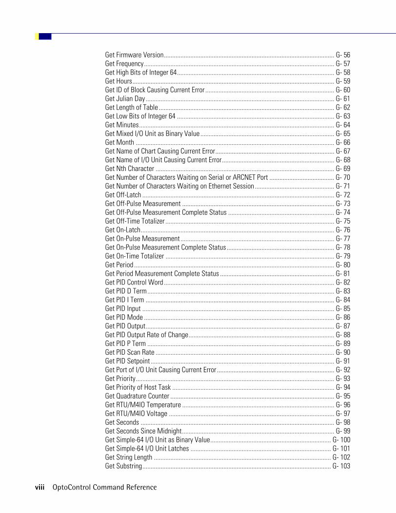
Get Firmware Version....................................................................................................... G- 56Get Frequency................................................................................................................... G- 57Get High Bits of Integer 64............................................................................................... G- 58Get Hours.......................................................................................................................... G- 59Get ID of Block Causing Current Error .............................................................................. G- 60Get Julian Day .................................................................................................................. G- 61Get Length of Table .......................................................................................................... G- 62Get Low Bits of Integer 64 ............................................................................................... G- 63Get Minutes...................................................................................................................... G- 64Get Mixed I/O Unit as Binary Value ................................................................................. G- 65Get Month ........................................................................................................................ G- 66Get Name of Chart Causing Current Error........................................................................ G- 67Get Name of I/O Unit Causing Current Error.................................................................... G- 68Get Nth Character ............................................................................................................ G- 69Get Number of Characters Waiting on Serial or ARCNET Port ....................................... G- 70Get Number of Characters Waiting on Ethernet Session ................................................ G- 71Get Off-Latch .................................................................................................................... G- 72Get Off-Pulse Measurement ............................................................................................ G- 73Get Off-Pulse Measurement Complete Status ................................................................ G- 74Get Off-Time Totalizer ...................................................................................................... G- 75Get On-Latch..................................................................................................................... G- 76Get On-Pulse Measurement ............................................................................................. G- 77Get On-Pulse Measurement Complete Status ................................................................. G- 78Get On-Time Totalizer ...................................................................................................... G- 79Get Period ......................................................................................................................... G- 80Get Period Measurement Complete Status ..................................................................... G- 81Get PID Control Word ....................................................................................................... G- 82Get PID D Term................................................................................................................. G- 83Get PID I Term .................................................................................................................. G- 84Get PID Input .................................................................................................................... G- 85Get PID Mode ................................................................................................................... G- 86Get PID Output.................................................................................................................. G- 87Get PID Output Rate of Change........................................................................................ G- 88Get PID P Term ................................................................................................................. G- 89Get PID Scan Rate ............................................................................................................ G- 90Get PID Setpoint ............................................................................................................... G- 91Get Port of I/O Unit Causing Current Error ....................................................................... G- 92Get Priority........................................................................................................................ G- 93Get Priority of Host Task .................................................................................................. G- 94Get Quadrature Counter ................................................................................................... G- 95Get RTU/M4IO Temperature ............................................................................................ G- 96Get RTU/M4IO Voltage .................................................................................................... G- 97Get Seconds ..................................................................................................................... G- 98Get Seconds Since Midnight............................................................................................ G- 99Get Simple-64 I/O Unit as Binary Value......................................................................... G- 100Get Simple-64 I/O Unit Latches ..................................................................................... G- 101Get String Length ........................................................................................................... G- 102Get Substring.................................................................................................................. G- 103
viii OptoControl Command Reference

Get System Time .............................................................................................................G- 104Get Year...........................................................................................................................G- 105Greater? ...........................................................................................................................G- 106Greater Than or Equal?....................................................................................................G- 107Greater Than or Equal to Table Element? .......................................................................G- 108Greater Than Table Element?..........................................................................................G- 109
H ...................................................................................................................H-1Host Task Received a Message? ........................................................................................H- 1Hyperbolic Cosine................................................................................................................H- 2Hyperbolic Sine ...................................................................................................................H- 3Hyperbolic Tangent .............................................................................................................H- 4
I ..................................................................................................................... I-1Increment Variable ............................................................................................................... I- 1Interrupt Disabled for Event? ............................................................................................... I- 2Interrupt Enabled for Event?................................................................................................. I- 3Interrupt on Port0?................................................................................................................ I- 4Interrupt on Port1?................................................................................................................ I- 4Interrupt on Port2?................................................................................................................ I- 5Interrupt on Port3?................................................................................................................ I- 6Interrupt on Port6?................................................................................................................ I- 6I/O Point Communication Enabled?...................................................................................... I- 7I/O Unit Communication Enabled? ....................................................................................... I- 8I/O Unit Ready? .................................................................................................................... I- 9IVAL Set Analog from Table............................................................................................... I- 10IVAL Set Analog Point ........................................................................................................ I- 11IVAL Set Counter ................................................................................................................ I- 12IVAL Set Digital Binary....................................................................................................... I- 13IVAL Set Frequency ............................................................................................................ I- 14IVAL Set Off-Latch.............................................................................................................. I- 15IVAL Set Off-Pulse .............................................................................................................. I- 16IVAL Set Off-Totalizer......................................................................................................... I- 17IVAL Set On-Latch .............................................................................................................. I- 18IVAL Set On-Pulse .............................................................................................................. I- 19IVAL Set On-Totalizer ......................................................................................................... I- 20IVAL Set Period................................................................................................................... I- 21IVAL Set PID Control Word................................................................................................. I- 22IVAL Set PID Process Term................................................................................................. I- 23IVAL Set Quadrature Counter ............................................................................................. I- 24IVAL Set TPO Percent ......................................................................................................... I- 25IVAL Set TPO Period ........................................................................................................... I- 26IVAL Turn Off ...................................................................................................................... I- 27IVAL Turn On....................................................................................................................... I- 28
OptoControl Command Reference ix

L ....................................................................................................................L-1Less? .................................................................................................................................... L- 1Less Than or Equal?............................................................................................................. L- 2Less Than or Equal to Table Element? ................................................................................ L- 3Less Than Table Element?................................................................................................... L- 5Low RAM Backup Battery?.................................................................................................. L- 6
M ................................................................................................................. M-1Make Integer 64 ................................................................................................................ M- 1Maximum........................................................................................................................... M- 2Minimum ........................................................................................................................... M- 3Modulo .............................................................................................................................. M- 4Move.................................................................................................................................. M- 5Move 32 Bits ..................................................................................................................... M- 6Move Analog I/O Unit to Table ......................................................................................... M- 7Move Digital I/O Unit to Table .......................................................................................... M- 8Move Digital I/O Unit to Table Element............................................................................ M- 9Move from Pointer Table Element .................................................................................. M- 10Move from String Table .................................................................................................. M- 11Move from Table Element ............................................................................................... M- 12Move Mixed I/O Unit to Table ........................................................................................ M- 13Move Simple-64 I/O Unit to Table .................................................................................. M- 14Move String ..................................................................................................................... M- 15Move Table Element to Digital I/O Unit.......................................................................... M- 16Move Table Element to Table ......................................................................................... M- 17Move Table to Analog I/O Unit ....................................................................................... M- 17Move Table to Digital I/O Unit ........................................................................................ M- 19Move Table to Mixed I/O Unit ........................................................................................ M- 20Move Table to Simple-64 I/O Unit .................................................................................. M- 21Move Table to Table ....................................................................................................... M- 22Move to Pointer ............................................................................................................... M- 23Move to Pointer Table ..................................................................................................... M- 24Move to String Table....................................................................................................... M- 25Move to Table Element ................................................................................................... M- 26Multiply ........................................................................................................................... M- 27
N ..................................................................................................................N-1Natural Log ......................................................................................................................... N- 1NOT..................................................................................................................................... N- 2NOT? ................................................................................................................................... N- 3Not Equal? .......................................................................................................................... N- 4Not Equal to Table Element?.............................................................................................. N- 5
O ..................................................................................................................O-1Off? ..................................................................................................................................... O- 1Off-Latch Set?..................................................................................................................... O- 2
x OptoControl Command Reference

On?.......................................................................................................................................O- 3On-Latch Set? ......................................................................................................................O- 4Open Ethernet Session........................................................................................................O- 5OR ........................................................................................................................................O- 6OR? ......................................................................................................................................O- 8
P ................................................................................................................... P-1Pause Timer ......................................................................................................................... P- 1PID Loop Communication Enabled?..................................................................................... P- 2Pointer Equal to NULL?........................................................................................................ P- 3Pointer Table Element Equal to NULL? ............................................................................... P- 4
R ................................................................................................................... R-1Raise e to Power .................................................................................................................R- 1Raise to Power ....................................................................................................................R- 2Ramp Analog Output ...........................................................................................................R- 3Read Byte from PC Memory (ISA only)................................................................................R- 4Read Byte from PC Port (ISA only).......................................................................................R- 5Read Event/Reaction Hold Buffer .......................................................................................R- 6Read Numeric Table from I/O Memory Map ......................................................................R- 6Read Numeric Variable from I/O Memory Map..................................................................R- 8Read String Table from I/O Memory Map ..........................................................................R- 9Read String Variable from I/O Memory Map....................................................................R- 11Read Word from PC Memory (ISA only) ............................................................................R- 12Read Word from PC Port (ISA only) ...................................................................................R- 13Receive Character via Serial Port......................................................................................R- 14Receive N Characters via ARCNET ...................................................................................R- 15Receive N Characters via Ethernet ...................................................................................R- 16Receive N Characters via Serial Port ................................................................................R- 18Receive String via ARCNET...............................................................................................R- 19Receive String via Ethernet ...............................................................................................R- 20Receive String via Serial Port............................................................................................R- 21Receive Table via ARCNET................................................................................................R- 23Receive Table via Ethernet................................................................................................R- 24Receive Table via Serial Port ............................................................................................R- 25Remove Current Error and Point to Next Error ..................................................................R- 26Reset Controller.................................................................................................................R- 27Retrieve Strategy CRC.......................................................................................................R- 28Round.................................................................................................................................R- 29
S ................................................................................................................... S-1Seed Random Number ........................................................................................................S- 1Set Analog Filter Weight.....................................................................................................S- 2Set Analog Gain ..................................................................................................................S- 4Set Analog Offset ................................................................................................................S- 5Set Analog Totalizer Rate ...................................................................................................S- 6
OptoControl Command Reference xi

Set Analog TPO Period ........................................................................................................S- 8Set ARCNET Host Destination Address ..............................................................................S- 9Set ARCNET Destination Address on Port ........................................................................S- 10Set ARCNET Mode Raw....................................................................................................S- 11Set ARCNET Mode Standard ............................................................................................S- 12Set ARCNET Peer Destination Address ............................................................................S- 13Set Date.............................................................................................................................S- 14Set Day ..............................................................................................................................S- 15Set Day of Week ...............................................................................................................S- 16Set Digital I/O Unit from MOMO Masks...........................................................................S- 17Set Digital-64 I/O Unit from MOMO Masks .....................................................................S- 18Set Down Timer Preset Value ...........................................................................................S- 19Set End-of-Message Terminator .......................................................................................S- 20Set Hours ...........................................................................................................................S- 21Set I/O Unit Configured Flag .............................................................................................S- 22Set Minutes .......................................................................................................................S- 23Set Mixed I/O Unit from MOMO Masks ...........................................................................S- 24Set Month..........................................................................................................................S- 25Set Nth Character..............................................................................................................S- 26Set Number of Retries to All I/O Units .............................................................................S- 27Set PC Byte Swap Mode (ISA only)...................................................................................S- 28Set PID Control Word ........................................................................................................S- 29Set PID D Term ..................................................................................................................S- 30Set PID I Term....................................................................................................................S- 31Set PID Input......................................................................................................................S- 32Set PID Mode to Auto .......................................................................................................S- 33Set PID Mode to Manual...................................................................................................S- 34Set PID Output Rate of Change .........................................................................................S- 35Set PID P Term...................................................................................................................S- 36Set PID Scan Rate .............................................................................................................S- 37Set PID Setpoint ................................................................................................................S- 38Set Priority .........................................................................................................................S- 39Set Priority of Host Task....................................................................................................S- 40Set Seconds.......................................................................................................................S- 41Set Simple-64 I/O Unit from MOMO Masks .....................................................................S- 42Set Time ............................................................................................................................S- 43Set TPO Percent.................................................................................................................S- 44Set TPO Period...................................................................................................................S- 45Set Up Timer Target Value ................................................................................................S- 46Set Variable False .............................................................................................................S- 47Set Variable True...............................................................................................................S- 48Set Year .............................................................................................................................S- 49Shift Table Elements .........................................................................................................S- 50Sine....................................................................................................................................S- 51Square Root .......................................................................................................................S- 52Start Chart .........................................................................................................................S- 53Start Continuous Square Wave.........................................................................................S- 54Start Counter .....................................................................................................................S- 55
xii OptoControl Command Reference

Start Default Host Task .....................................................................................................S- 56Start Host Task (ASCII) ......................................................................................................S- 57Start Host Task (Binary).....................................................................................................S- 58Start Off-Pulse ...................................................................................................................S- 59Start On-Pulse ...................................................................................................................S- 60Start Quadrature Counter ..................................................................................................S- 61Start Timer.........................................................................................................................S- 62Stop Chart..........................................................................................................................S- 63Stop Chart on Error ............................................................................................................S- 64Stop Counter......................................................................................................................S- 65Stop Host Task ..................................................................................................................S- 66Stop Quadrature Counter ..................................................................................................S- 67Stop Timer .........................................................................................................................S- 68String Equal? .....................................................................................................................S- 69String Equal to String Table Element? ..............................................................................S- 70Subtract .............................................................................................................................S- 71Suspend Chart ...................................................................................................................S- 72Suspend Chart on Error .....................................................................................................S- 73Suspend Default Host Task ...............................................................................................S- 74
T .....................................................................................................................T-1Table Element Bit Clear....................................................................................................... T- 1Table Element Bit Set.......................................................................................................... T- 2Table Element Bit Test ........................................................................................................ T- 3Tangent................................................................................................................................ T- 4Test Equal ............................................................................................................................ T- 5Test Equal Strings ............................................................................................................... T- 7Test Greater......................................................................................................................... T- 8Test Greater or Equal .......................................................................................................... T- 9Test Less............................................................................................................................ T- 10Test Less or Equal ............................................................................................................. T- 12Test Not Equal ................................................................................................................... T- 13Test Within Limits ............................................................................................................. T- 14Timer Expired? ................................................................................................................... T- 15Transmit Character via Serial Port .................................................................................... T- 16Transmit NewLine via Serial Port ..................................................................................... T- 17Transmit String via ARCNET ............................................................................................. T- 19Transmit String via Ethernet ............................................................................................. T- 20Transmit String via Serial Port .......................................................................................... T- 22Transmit Table via ARCNET .............................................................................................. T- 23Transmit Table via Ethernet .............................................................................................. T- 24Transmit Table via Serial Port ........................................................................................... T- 25Transmit/Receive Mistic I/O Hex String with Checksum ................................................. T- 27Transmit/Receive Mistic I/O Hex String with CRC ........................................................... T- 28Transmit/Receive OPTOMUX String ................................................................................. T- 29Transmit/Receive String via ARCNET ............................................................................... T- 31Transmit/Receive String via Ethernet ............................................................................... T- 32
OptoControl Command Reference xiii

Transmit/Receive String via Serial Port ............................................................................T- 34Truncate.............................................................................................................................T- 36Turn Off..............................................................................................................................T- 37Turn Off RTS ......................................................................................................................T- 38Turn Off RTS After Next Character ...................................................................................T- 39Turn On ..............................................................................................................................T- 40Turn On RTS.......................................................................................................................T- 41
U ................................................................................................................... U-1Up Timer Target Time Reached? ........................................................................................ U- 1
V ................................................................................................................... V-1Variable False? ....................................................................................................................V- 1Variable True? .....................................................................................................................V- 2Verify Checksum on String ..................................................................................................V- 3Verify Forward CCITT on String ...........................................................................................V- 4Verify Forward CRC-16 on String ........................................................................................V- 5Verify Reverse CCITT on String ...........................................................................................V- 6Verify Reverse CRC-16 on String.........................................................................................V- 7
W ................................................................................................................W-1Within Limits? ................................................................................................................... W- 1Write Byte to PC Memory (ISA only) ................................................................................. W- 3Write Byte to PC Port (ISA only) ........................................................................................ W- 4Write I/O Unit Configuration to EEPROM ......................................................................... W- 5Write Numeric Table to I/O Memory Map........................................................................ W- 6Write Numeric Variable to I/O Memory Map ................................................................... W- 8Write String Table to I/O Memory Map............................................................................ W- 9Write String Variable to I/O Memory Map ..................................................................... W- 11Write Word to PC Memory (ISA only) ............................................................................. W- 12Write Word to PC Port (ISA only) .................................................................................... W- 13
X ................................................................................................................... X-1XOR......................................................................................................................................X- 1XOR? ....................................................................................................................................X- 3
Index ..................................................................................................... Index-1
xiv OptoControl Command Reference

Welcome to the OptoControl Command Reference
Welcome to OptoControl™, Opto 22’s visual control language for Microsoft®Windows® systems, and a part of the Opto 22 FactoryFloor® suite of products. OptoControl provides a complete and powerful set of commands for all your industrial control needs.
About this ReferenceThis command reference describes in detail all OptoControl programming commands, or instructions.The commands are listed alphabetically. The OptoControl User’s Guide, in a separate binder, explains how to install and use OptoControl. For helpful information on using commands, see Chapter 10, “Programming with Commands,” in the user’s guide.
This reference assumes that you are already familiar with Microsoft Windows on your personal computer. If you are not familiar with Windows or your PC, refer to the documentation from Microsoft and your computer manufacturer.
Other FactoryFloor Resources
Documents and Online HelpTo help you understand and use the FactoryFloor suite of products, the following resources are provided:
• Online Help is available in OptoControl, OptoDisplay, OptoServer, and most of the OptoUtilities. To open online Help, choose Help➞Contents and Index in any screen.
• OptoControl User’s Guide, OptoDisplay User’s Guide, and OptoServer User’s Guide give step-by-step instructions for using each of these products. The OptoServer User’s Guide binder also contains a master FactoryFloor Glossary, which defines terms for all FactoryFloor products.
OptoControl Command Reference xv

Online versions (Adobe® Acrobat® format) of these and other FactoryFloor documents are available from the Help menu in your FactoryFloor application. To view a document, select Help➞Manuals, and then choose a document from the submenu.
• OptoControl Command Reference contains detailed information about each command (instruction) available in OptoControl.
• Two quick reference cards, OptoControl Commands and Beginner’s Guide to OptoControl Commands, are located in the front pocket of the OptoControl Command Reference.
• FactoryFloor resources are also available on the Opto 22 Web site at factoryfloor.opto22.com. You can conveniently access this and other sections of the Opto 22 Web site using the Help menu in your FactoryFloor application. Select Help➞Opto 22 on the Web, and then select an online resource from the submenu.
Product SupportIf you have any questions about FactoryFloor, you can call, fax, or e-mail Opto 22 Product Support.
Phone: 800-TEK-OPTO (835-6786)951-695-3080(Hours are Monday through Friday, 7 a.m. to 5 p.m. Pacific Time)
Fax: 951-695-3017
Email: [email protected]
Opto 22 website: www.opto22.com
When calling for technical support, be prepared to provide the following information about your system to the Product Support engineer:
• Software and version being used
• Controller firmware version
• PC configuration (type of processor, speed, memory, operating system)
• A complete description of your hardware and operating systems, including:– jumper configuration– accessories installed (such as expansion daughter cards)– type of power supply– types of I/O units installed– third-party devices installed (for example, barcode readers)
• Specific error messages seen.
NOTE: Email messages and phone calls to Opto 22 Product Support are grouped together and answered in the order received.
xvi OptoControl Command Reference

Commands by Command GroupOptoControl Command See pg OptoScript Equivalent (Arguments)
Digi
tal P
oint Clear All Latches C-24 ClearAllLatches(On I/O Unit)
Clear Counter C-25 ClearCounter(On Point)Clear Off-Latch C-28 ClearOffLatch(On Point)Clear On-Latch C-29 ClearOnLatch(On Point)Clear Quadrature Counter C-32 ClearQuadratureCounter(On Point)Generate N Pulses* G-4 GenerateNPulses(On Time (Seconds), Off Time
(Seconds), Number of Pulses, On Point)Get & Clear Counter G-14 GetClearCounter(From Point)Get & Clear Off-Latch G-19 GetClearOffLatch(From Point)Get & Clear On-Latch G-20 GetClearOnLatch(From Point)Get & Clear Quadrature Counter G-21 GetClearQuadratureCounter(From Point)Get & Restart Off-Pulse Measurement* G-23 GetRestartOffPulseMeasurement(From Point)Get & Restart Off-Time Totalizer* G-24 GetRestartOffTimeTotalizer(From Point)Get & Restart On-Pulse Measurement* G-25 GetRestartOnPulseMeasurement(From Point)Get & Restart On-Time Totalizer* G-26 GetRestartOnTimeTotalizer(From Point)Get & Restart Period* G-27 GetRestartPeriod(From Point)Get Counter G-44 GetCounter(From Point)Get Frequency G-57 GetFrequency(From Point)Get Off-Latch G-72 See Off-Latch Set?Get Off-Pulse Measurement* G-73 GetOffPulseMeasurement(From Point)Get Off-Pulse Measurement Complete
Status*G-74 GetOffPulseMeasurementCompleteStatus(From Point)
Get Off-Time Totalizer* G-75 GetOffTimeTotalizer(From Point)Get On-Latch G-76 See On-Latch Set?Get On-Pulse Measurement* G-77 GetOnPulseMeasurement(From Point)Get On-Pulse Measurement Complete
Status*G-78 GetOnPulseMeasurementCompleteStatus(From Point)
Get On-Time Totalizer* G-79 GetOnTimeTotalizer(From Point)Get Period* G-80 GetPeriod(From Point)Get Period Measurement Complete Status* G-81 GetPeriodMeasurementCompleteStatus(From Point)Get Quadrature Counter G-95 GetQuadratureCounter(On Point)Off? O-1 IsOff(Point)Off-Latch Set? O-2 IsOffLatchSet(On Point)On? O-3 IsOn(Point)On-Latch Set? O-4 IsOnLatchSet(On Point)Set TPO Percent* S-44 SetTpoPercent(To Percent, On Point)Set TPO Period* S-45 SetTpoPeriod(To Seconds, On Point)Start Continuous Square Wave* S-54 StartContinuousSquareWave(On Time (Seconds), Off Time
(Seconds), On Point)Start Counter S-55 StartCounter(On Point)Start Off-Pulse* S-59 StartOffPulse(Off Time (Seconds), On Point)Start On-Pulse* S-60 StartOnPulse(On Time (Seconds), On Point)Start Quadrature Counter S-61 StartQuadratureCounter(On Point)Stop Counter S-65 StopCounter(On Point)Stop Quadrature Counter S-67 StopQuadratureCounter(On Point)Turn Off T-37 TurnOff(Output)Turn On T-40 TurnOn(Output)*Not available on SNAP Ethernet-based I/O units
OptoControl Command Reference xvii

Anal
og P
oint Calculate & Set Analog Gain C-1 CalcSetAnalogGain(On Point)
Calculate & Set Analog Offset C-3 CalcSetAnalogOffset(On Point)Get & Clear Analog Filtered Value* G-10 GetClearAnalogFilteredValue(From)Get & Clear Analog Maximum Value G-11 GetClearAnalogMaxValue(From)Get & Clear Analog Minimum Value G-12 GetClearAnalogMinValue(From)Get & Clear Analog Totalizer Value* G-13 GetClearAnalogTotalizerValue(From)Get Analog Filtered Value* G-30 GetAnalogFilteredValue(From)Get Analog Lower Clamp G-31 GetAnalogLowerClamp(From)Get Analog Maximum Value G-32 GetAnalogMaxValue(From)Get Analog Minimum Value G-33 GetAnalogMinValue(From)Get Analog Square Root Filtered Value* G-34 GetAnalogSquareRootFilteredValue(From)Get Analog Square Root Value* G-35 GetAnalogSquareRootValue(From)Get Analog Totalizer Value* G-36 GetAnalogTotalizerValue(From)Get Analog Upper Clamp G-37 GetAnalogUpperClamp(From)Ramp Analog Output* R-3 RampAnalogOutput(Ramp Endpoint, Units/Sec, Point to
Ramp)Set Analog Filter Weight* S-2 SetAnalogFilterWeight(To, On Point)Set Analog Gain S-4 SetAnalogGain(To, On Point)Set Analog Offset S-5 SetAnalogOffset(To, On Point)Set Analog Totalizer Rate* S-6 SetAnalogTotalizerRate(To Seconds, On Point)Set Analog TPO Period S-8 SetAnalogTpoPeriod(To, On Point)*Not available on SNAP Ethernet-based I/O units
Cha
rt Call Chart C-6 CallChart(Chart)Calling Chart Running? C-7 IsCallingChartRunning()Calling Chart Stopped? C-8 IsCallingChartStopped()Calling Chart Suspended? C-9 IsCallingChartSuspended()Chart Running? C-13 IsChartRunning(Chart)Chart Stopped? C-14 IsChartStopped(Chart)Chart Suspended? C-15 IsChartSuspended(Chart)Continue Calling Chart C-43 ContinueCallingChart()Continue Chart C-44 ContinueChart(Chart)Get Chart Status G-41 GetChartStatus(Chart)Get Priority G-93 GetPriority()Get Priority of Host Task G-94 GetPriorityOfHostTask(On Port)Host Task Received A Message? H-1 HasHostTaskReceivedMessage(On Port)Set Priority S-39 SetPriority()Set Priority Of Host Task S-40 SetPriorityOfHostTask(On Port)Start Chart S-53 StartChart(Chart)Start Default Host Task S-56 StartDefaultHostTask()Start Host Task (ASCII) S-57 StartHostTaskAscii(On Port)Start Host Task (Binary) S-58 StartHostTaskBinary(On Port)Stop Chart S-63 StopChart(Chart)Stop Chart on Error S-64 StopChartOnError()Stop Host Task S-66 StopHostTask(On Port)Suspend Chart S-72 SuspendChart(Chart)Suspend Chart on Error S-73 SuspendChartOnError()Suspend Default Host Task S-74 SuspendDefaultHostTask()
OptoControl Command See pg OptoScript Equivalent (Arguments)
xviii OptoControl Command Reference
I/O U
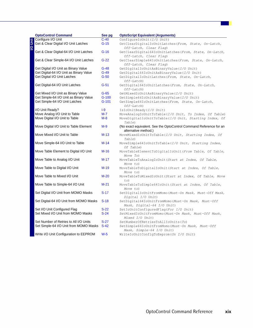
nit Configure I/O Unit C-40 ConfigureIoUnit(I/O Unit)
Get & Clear Digital I/O Unit Latches G-15 GetClearDigitalIoUnitLatches(From, State, On-Latch, Off-Latch, Clear Flag)
Get & Clear Digital-64 I/O Unit Latches G-16 GetClearDigital64IoUnitLatches(From, State, On-Latch, Off-Latch, Clear Flag)
Get & Clear Simple-64 I/O Unit Latches G-22 GetClearSimple64IoUnitLatches(From, State, On-Latch, Off-Latch, Clear Flag)
Get Digital I/O Unit as Binary Value G-48 GetDigitalIoUnitAsBinaryValue(I/O Unit)Get Digital-64 I/O Unit as Binary Value G-49 GetDigital64IoUnitAsBinaryValue(I/O Unit)Get Digital I/O Unit Latches G-50 GetDigitalIoUnitLatches(From, State, On-Latch,
Off-Latch)Get Digital-64 I/O Unit Latches G-51 GetDigital64IoUnitLatches(From, State, On-Latch,
Off-Latch)Get Mixed I/O Unit as Binary Value G-65 GetMixedIoUnitAsBinaryValue(I/O Unit)Get Simple-64 I/O Unit as Binary Value G-100 GetSimple64IoUnitAsBinaryValue(I/O Unit)Get Simple-64 I/O Unit Latches G-101 GetSimple64IoUnitLatches(From, State, On-Latch,
Off-Latch)I/O Unit Ready? I-9 IsIoUnitReady(I/O Unit)Move Analog I/O Unit to Table M-7 MoveAnalogIoUnitToTable(I/O Unit, To Index, Of Table)Move Digital I/O Unit to Table M-8 MoveDigitalIoUnitToTable(I/O Unit, Starting Index, Of
Table)Move Digital I/O Unit to Table Element M-9 (No exact equivalent. See the OptoControl Command Reference for an
alternative method.)Move Mixed I/O Unit to Table M-13 MoveMixedIoUnitToTable(I/O Unit, Starting Index, Of
Table)Move Simple-64 I/O Unit to Table M-14 MoveSimple64IoUnitToTable(I/O Unit, Starting Index,
Of Table)Move Table Element to Digital I/O Unit M-16 MoveTableElementToDigitalIoUnit(From Table, Of Table,
Move To)Move Table to Analog I/O Unit M-17 MoveTableToAnalogIoUnit(Start at Index, Of Table,
Move to)Move Table to Digital I/O Unit M-19 MoveTableToDigitalIoUnit(Start at Index, Of Table,
Move to)Move Table to Mixed I/O Unit M-20 MoveTableToMixedIoUnit(Start at Index, Of Table, Move
to)Move Table to Simple-64 I/O Unit M-21 MoveTableToSimple64IoUnit(Start at Index, Of Table,
Move to)Set Digital I/O Unit from MOMO Masks S-17 SetDigitalIoUnitFromMomo(Must-On Mask, Must-Off Mask,
Digital I/O Unit)Set Digital-64 I/O Unit from MOMO Masks S-18 SetDigital64IoUnitFromMomo(Must-On Mask, Must-Off
Mask, Digital-64 I/O Unit)Set I/O Unit Configured Flag S-22 SetIoUnitConfiguredFlag(For I/O Unit)Set Mixed I/O Unit from MOMO Masks S-24 SetMixedIoUnitFromMomo(Must-On Mask, Must-Off Mask,
Mixed I/O Unit)Set Number of Retries to All I/O Units S-27 SetNumberOfRetriesToAllIoUnits(To)Set Simple-64 I/O Unit from MOMO Masks S-42 SetSimple64IoUnitFromMomo(Must-On Mask, Must-Off
Mask, Simple-64 I/O Unit)Write I/O Unit Configuration to EEPROM W-5 WriteIoUnitConfigToEeprom(On I/O Unit)
OptoControl Command See pg OptoScript Equivalent (Arguments)
OptoControl Command Reference xix

Mis
cella
neou
s Comment (Block) C-35 /* block comment */Comment (Single Line) C-36 // single line commentContinue Timer C-45 ContinueTimer(Timer)Delay (mSec) D-2 DelayMsec(Milliseconds)Delay (Sec) D-3 DelaySec(Seconds)Down Timer Expired? D-22 HasDownTimerExpired(Down Timer)Float Valid? F-3 IsFloatValid(Float)Generate Reverse CRC-16 on Table
(32 bit)G-8 GenerateReverseCrc16OnTable32(Start Value, Table,
Starting Element, Number of Elements)Get Length of Table G-62 GetLengthOfTable(Table)Move M-5 x = y;Move from Table Element M-12 x = nt[0];Move Table Element to Table M-17 nt1[0] = nt2[5];Move Table to Table M-22 MoveTableToTable(From Table, From Index, To Table, To
Index, Length)Move to Table Element M-26 nt[0] = x;Pause Timer P-1 PauseTimer(Timer)Set Down Timer Preset Value S-19 SetDownTimerPreset(Target Value, Down Timer)Set Up Timer Target Value S-46 SetUpTimerTarget(Target Value, Up Timer)Shift Table Elements S-50 ShiftTableElements(Shift Count, Table)Start Timer S-62 StartTimer(Timer)Stop Timer S-68 StopTimer(Timer)Timer Expired? T-15 HasTimerExpired(Timer)Up Timer Target Time Reached? U-1 HasUpTimerReachedTargetTime(Up Timer)
PID Clamp PID Output* C-20 ClampPidOutput(High Clamp, Low Clamp, On PID Loop)
Clamp PID Setpoint* C-21 ClampPidSetpoint(High Clamp, Low Clamp, On PID Loop)Disable PID Output* D-15 DisablePidOutput(Of PID Loop)Disable PID Output Tracking in Manual
Mode*D-16 DisablePidOutputTrackingInManualMode(On PID Loop)
Disable PID Setpoint Tracking in Manual Mode*
D-17 DisablePidSetpointTrackingInManualMode(On PID Loop)
Enable PID Output* E-11 EnablePidOutput(Of PID Loop)Enable PID Output Tracking in Manual
Mode*E-12 EnablePidOutputTrackingInManualMode(On PID Loop)
Enable PID Setpoint Tracking in Manual Mode*
E-13 EnablePidSetpointTrackingInManualMode(On PID Loop)
Get PID Control Word* G-82 GetPidControlWord(From PID Loop)Get PID D Term* G-83 GetPidDTerm(From PID Loop)Get PID I Term* G-84 GetPidITerm(From PID Loop)Get PID Input* G-85 GetPidInput(From PID Loop)Get PID Mode* G-86 GetPidMode(From PID Loop)Get PID Output* G-87 GetPidOutput(From PID Loop)Get PID Output Rate of Change* G-88 GetPidOutputRateOfChange(From PID Loop)Get PID P Term* G-89 GetPidPTerm(From PID Loop)Get PID Scan Rate* G-90 GetPidScanRate(From PID Loop)Get PID Setpoint* G-91 GetPidSetpoint(From PID Loop)Set PID Control Word* S-29 SetPidControlWord(On Mask, Off Mask, For PID Loop)Set PID D Term* S-30 SetPidDTerm(To, On PID Loop)Set PID I Term* S-31 SetPidITerm(To, On PID Loop)Set PID Input* S-32 SetPidInput(To, On PID Loop)Set PID Mode to Auto* S-33 SetPidModeToAuto(On PID Loop)Set PID Mode to Manual* S-34 SetPidModeToManual(On PID Loop)Set PID Output Rate of Change* S-35 SetPidOutputRateOfChange(To, On PID Loop)Set PID P Term* S-36 SetPidPTerm(To, On PID Loop)Set PID Scan Rate* S-37 SetPidScanRate(To, On PID Loop)Set PID Setpoint* S-38 SetPidSetpoint(To, On PID Loop)*Not available on SNAP Ethernet brains
OptoControl Command See pg OptoScript Equivalent (Arguments)
xx OptoControl Command Reference

Con
trolle
r Add User Error to Queue A-4 AddUserErrorToQueue(Error Number)Add User I/O Unit Error to Queue A-5 AddUserIoUnitErrorToQueue(Error Number, I/O Unit)Calculate & Store Srategy CRC C-4 CalcStoreStrategyCRC()Calculate Strategy CRC C-5 CalcStrategyCrc()Caused a Chart Error? C-10 HasChartCausedError(Chart)Caused an I/O Unit Error? C-11 HasIoUnitCausedError(I/O Unit)Clear All Errors C-22 ClearAllErrors()Clear PC Byte Swap Mode (ISA only) C-30 ClearPcByteSwapMode()Disable I/O Unit Causing Current Error D-13 DisableIoUnitCausingCurrentError()Enable I/O Unit Causing Current Error E-9 EnableIoUnitCausingCurrentError()Error? E-19 IsErrorPresent()Error on I/O Unit? E-20 IsErrorOnIoUnit()Get Address of I/O Unit Causing Current
ErrorG-29 GetAddressOfIoUnitCausingCurrentError()
Get Controller Address G-42 GetControllerAddress()Get Controller Type G-43 GetControllerType()Get Default Host Port G-47 GetDefaultHostPort()Get Error Code of Current Error G-52 GetErrorCodeOfCurrentError()Get Error Count G-53 GetErrorCount()Get Firmware Version G-56 GetFirmwareVersion(Put in)Get ID of Block Causing Current Error G-60 GetIdOfBlockCausingCurrentError()Get Name of Chart Causing Current Error G-67 GetNameOfChartCausingCurrentError(Put in)Get Name of I/O Unit Causing Current Error G-68 GetNameOfIoUnitCausingCurrentError(Put in)Get Port of I/O Unit Causing Current Error G-92 GetPortOfIoUnitCausingCurrentError()Get RTU/M4IO Temperature G-96 GetRtuM4IoTemperature()Get RTU/M4IO Voltage G-97 GetRtuM4IoVoltage()Low RAM Backup Battery? IsRamBackupBatteryLow()Read Byte from PC Memory (ISA only) R-4 ReadByteFromPcMemory(From Address)Read Byte from PC Port (ISA only) R-5 ReadByteFromPcPort(From Address)Read Word from PC Memory (ISA only) R-12 ReadWordFromPcMemory(From Address)Read Word from PC Port (ISA only) R-13 ReadWordFromPcPort(From Address)Remove Current Error and Point to Next
ErrorR-26 RemoveCurrentError()
Reset Controller R-27 ResetController()Retrieve Strategy CRC R-4 RetrieveStrategyCrc()Set PC Byte Swap Mode (ISA only) S-28 SetPcByteSwapMode()Write Byte to PC Memory (ISA only) W-3 WriteByteToPcMemory(Byte, To Address)Write Byte to PC Port (ISA only) W-4 WriteByteToPcPort(Byte, To Address)Write Word to PC Memory (ISA only) W-12 WriteWordToPcMemory(Word, To Address)Write Word to PC Port (ISA only) W-13 WriteWordToPcPort(Word, To Address)
OptoControl Command See pg OptoScript Equivalent (Arguments)
OptoControl Command Reference xxi

Tim
e/Da
te Copy Date to String (DD/MM/YY) C-60 DateToStringDDMMYY(String)Copy Date to String (MM/DD/YY) C-61 DateToStringMMDDYY(String)Copy Time to String C-62 TimeToString(String)Get Day G-45 GetDay()Get Day of Week G-46 GetDayOfWeek()Get Hours G-59 GetHours()Get Julian Day G-61 GetJulianDay()Get Minutes G-64 GetMinutes()Get Month G-66 GetMonth()Get Seconds G-98 GetSeconds()Get Seconds Since Midnight G-99 GetSecondsSinceMidnight()Get System Time G-104 GetSystemTime()Get Year G-105 GetYear()Set Date S-14 SetDate(To)Set Day S-15 SetDay(To)Set Day of Week S-16 SetDayOfWeek(To)Set Hours S-21 SetHours(To)Set Minutes S-23 SetMinutes(To)Set Month S-25 SetMonth(To)Set Seconds S-41 SetSeconds(To)Set Time S-43 SetTime(To)Set Year S-49 SetYear(To)
Com
mun
icat
ion—
I/O Convert Mistic I/O Hex to Float C-49 MisticIoHexToFloat(Convert)Convert Number to Mistic I/O Hex C-52 NumberToMisticIoHex(Convert, Put Result in)Read Numeric Table from I/O Memory Map R-6 ReadNumTableFromIoMemMap(Length, Start Index, I/O
Unit, Mem address, To)Read Numeric Variable from I/O Memory
MapR-8 ReadNumVarFromIoMemMap(I/O Unit, Mem address, To)
Read String Table from I/O Memory Map R-9 ReadStrTableFromIoMemMap(Length, Start Index, I/O Unit, Mem address, To)
Read String Variable from I/O Memory Map R-11 ReadStrVarFromIoMemMap(Length, I/O Unit, Mem address, To)
Transmit/Receive Mistic I/O Hex String with Checksum
T-27 TransReceMisticIoHexStringWithChecksum(Hex String, On Port, Put Result in)
Transmit/Receive Mistic I/O Hex String with CRC
T-28 TransReceMisticIoHexStringWithCrc(Hex String, On Port, Put Result in)
Transmit/Receive OPTOMUX String T-29 TransReceOptomuxString(String, On Port, Put Result in)
Write Numeric Table to I/O Memory Map W-6 WriteNumTableToIoMemMap(Length, Start Index, I/O Unit, Mem address, Table)
Write Numeric Variable to I/O Memory Map W-8 WriteNumVarToIoMemMap(I/O Unit, Mem address, Variable)
Write String Table to I/O Memory Map W-9 WriteStrTableToIoMemMap(Length, Start Index, I/O Unit, Mem address, Table)
Write String Variable to I/O Memory Map
W-11 WriteStrVarToIoMemMap(I/O Unit, Mem address, Variable)
OptoControl Command See pg OptoScript Equivalent (Arguments)
xxii OptoControl Command Reference

Com
mun
icat
ion—
Net
wor
k Accept Session on TCP Port A-2 AcceptSessionOnTcpPort(TCP Port)ARCNET Connected? A-10 IsArcnetConnected()ARCNET Message Address Equal To? A-11 IsArcnetMsgAddressEqual(Address)ARCNET Node Present? A-12 IsArcnetNodePresent(Address)Close Ethernet Session C-34 CloseEthernetSession(Session, On Port)Ethernet Session Open? E-21 IsEnetSessionOpen(Session)Get ARCNET Destination Address on Port G-39 GetArcnetDestAddressOnPort(On Port)Get ARCNET Host Destination Address G-38 GetArcnetHostDestAddress()Get ARCNET Peer Destination Address G-40 GetArcnetPeerDestAddress()Get Ethernet Session Name G-54 GetEthernetSessionName(Session, Put in)Get Number of Characters Waiting on
Ethernet SessionG-71 GetNumCharsWaitingOnEnetSession(On Session)
Open Ethernet Session O-5 OpenEthernetSession(Session Name, On Port)Receive N Characters via ARCNET R-15 ReceiveNCharsViaArcnet(Put in, Num. Characters, From
Port)Receive N Characters via Ethernet R-16 ReceiveNCharsViaEthernet(Put in, Num. Characters,
From Session)Receive String via ARCNET R-19 ReceiveStringViaArcnet(Put in, From Port)Receive String via Ethernet R-20 ReceiveStringViaEthernet(Put in, From Session)Receive Table via ARCNET R-23 ReceiveTableViaArcnet(Start at Index, Of Table, From
Port)Receive Table via Ethernet R-24 ReceiveTableViaEthernet(Start at Index, Of Table,
From Session)Set ARCNET Destination Address on Port S-10 SetArcnetDestAddressOnPort(To Address, On Port)Set ARCNET Host Destination Address S-9 SetArcnetHostDestAddress(To)Set ARCNET Mode Raw S-11 SetArcnetModeRaw()Set ARCNET Mode Standard S-12 SetArcnetModeStandard()Set ARCNET Peer Destination Address S-13 SetArcnetPeerDestAddress(To)Transmit String via ARCNET T-19 TransStringViaArcnet(String, On Port)Transmit String via Ethernet T-20 TransStringViaEthernet(String, Via Session, On Port)Transmit Table via ARCNET T-23 TransTableViaArcnet(Start at Index, Of Table, On Port)Transmit Table via Ethernet T-24 TransTableViaEthernet(Start at Index, Of Table, Via
Session, On Port)Transmit/Receive String via ARCNET T-31 TransReceStringViaArcnet(String, On Port, Put Result
in)Transmit/Receive String via Ethernet T-32 TransReceStringViaEthernet(String, Via Session, On
Port, Put Result in)
OptoControl Command See pg OptoScript Equivalent (Arguments)
OptoControl Command Reference xxiii

Mat
hem
atic
al Absolute Value A-1 AbsoluteValue(Of)Add A-3 x + yArccosine A-13 Arccosine(Of)Arcsine A-14 Arcsine(Of)Arctangent A-15 Arctangent(Of)Clamp Float Table Element C-16 ClampFloatTableElement(High Limit, Low Limit, Element
Index, Of Float Table)Clamp Float Variable C-17 ClampFloatVariable(High Limit, Low Limit, Float
Variable)Clamp Integer 32 Table Element C-18 ClampInt32TableElement(High Limit, Low Limit, Element
Index, Of Integer 32 Table)Clamp Integer 32 Variable C-19 ClampInt32Variable(High Limit, Low Limit, Integer 32
Variable)Complement C-39 -xCosine C-63 Cosine(Of)Decrement Variable D-1 DecrementVariable(Variable)Divide D-21 x / yGenerate Random Number G-5 GenerateRandomNumber()Hyperbolic Cosine H-2 HyperbolicCosine(Of)Hyperbolic Sine H-3 HyperbolicSine(Of)Hyperbolic Tangent H-4 HyperbolicTangent(Of)Increment Variable I-1 IncrementVariable(Variable)Maximum M-2 Max(Compare, With)Minimum M-3 Min(Compare, With)Modulo M-4 x % yMultiply M-27 x * yNatural Log N-1 NaturalLog(Of)Raise e to Power R-1 RaiseEToPower(Exponent)Raise to Power R-2 Power(Raise, To the)Round R-29 Round(Value)Seed Random Number S-1 SeedRandomNumber()Sine S-51 Sine(Of)Square Root S-52 SquareRoot(Of)Subtract S-71 x - yTangent T-4 Tangent(Of)Truncate T-36 Truncate(Value)
OptoControl Command See pg OptoScript Equivalent (Arguments)
xxiv OptoControl Command Reference

Strin
g Append Character to String A-8 s1 += 'a';Append String to String A-9 s1 += s2;Convert Float to String C-45 FloatToString(Convert, Length, Decimals, Put Result
in)Convert Hex String to Number C-45 HexStringToNumber(Convert)Convert IEEE Hex String to Number C-48 IEEEHexStringToNumber(Convert)Convert Number to Formatted Hex String C-50 NumberToFormattedHexString(Convert, Length, Put
Result in)Convert Number to Hex String C-51 NumberToHexString(Convert, Put Result in)Convert Number to String C-53 NumberToString(Convert, Put Result in)Convert Number to String Field C-54 NumberToStringField(Convert, Length, Put Result in)Convert String to Float C-55 StringToFloat(Convert)Convert String to Integer 32 C-56 StringToInt32(Convert)Convert String to Integer 64 C-57 StringToInt64(Convert)Convert String to Lower Case C-59 StringToLowerCase(Convert)Convert String to Upper Case C-59 StringToUpperCase(Convert)Find Character in String F-1 FindCharacterInString(Find, Start at Index, Of
String)Find Substring in String F-2 FindSubstringInString(Find, Start at Index, Of
String)Generate Checksum on String G-1 GenerateChecksumOnString(Start Value, On String)Generate Forward CCITT on String G-2 GenerateForwardCcittOnString(Start Value, On String)Generate Forward CRC-16 on String G-3 GenerateForwardCrc16OnString(Start Value, On String)Generate Reverse CCITT on String G-6 GenerateReverseCcittOnString(Start Value, On String)Generate Reverse CRC-16 on String G-7 GenerateReverseCrc16OnString(Start Value, On String)Get Nth Character G-69 GetNthCharacter(From String, Index)Get String Length G-102 GetStringLength(Of String)Get Substring G-103 GetSubstring(From String, Start at Index, Num.
Characters, Put Result in)Move from String Table M-11 s = st[0];Move String M-15 s1 = s2;Move to String Table M-25 st[0] = s;Set Nth Character S-26 SetNthCharacter(To, In String, At Index)String Equal? S-69 s1 == s2String Equal to String Table Element? S-70 s == st[0]Test Equal Strings T-37 See String Equal?Verify Checksum on String V-3 VerifyChecksumOnString(Start Value, On String)Verify Forward CCITT on String V-4 VerifyForwardCcittOnString(Start Value, On String)Verify Forward CRC-16 on String V-5 VerifyForwardCrc16OnString(Start Value, On String)Verify Reverse CCITT on String V-6 VerifyReverseCcittOnString(Start Value, On String)Verify Reverse CRC-16 on String V-7 VerifyReverseCrc16OnString(Start Value, On String)
Poin
ters Clear Pointer C-30 pn1 = null;
Clear Pointer Table Element C-31 pt[0] = null;Move from Pointer Table Element M-10 pn = pt[0];Move to Pointer M-23 pn = &n;Move to Pointer Table M-24 pt[0] = &n;Pointer Equal to Null? P-3 pn == nullPointer Table Element Equal to Null? P-4 pt[0] == null
OptoControl Command See pg OptoScript Equivalent (Arguments)
OptoControl Command Reference xxv

Logi
cal AND A-6 x and y
AND? A-7 See ANDBit AND B-1 x bitand yBit AND? B-2 See Bit ANDBit Clear B-4 BitClear(Item, Bit to Clear)Bit NOT B-5 bitnot xBit NOT? B-6 See Bit NOTBit Off? B-8 IsBitOff(In, Bit)Bit On? B-9 IsBitOn(In, Bit)Bit OR B-10 x bitor yBit OR? B-11 See Bit ORBit Rotate B-12 BitRotate(Item, Count)Bit Set B-14 BitSet(Item, Bit to Set)Bit Shift B-15 x << nBitsToShiftBit Test B-17 BitTest(Item, Bit to Test)Bit XOR B-18 x bitxor yBit XOR? B-19 See Bit XOREqual? E-16 x == yEqual to Table Element? E-18 n == nt[0]Get High Bits of Integer 64 G-58 GetHighBitsOfInt64(High Bits From)Get Low Bits of Integer 64 G-63 GetLowBitsOfInt64(Integer 64)Greater? G-106 x > yGreater Than Table Element? G-109 x > nt[0]Greater Than or Equal? G-107 x >= yGreater Than or Equal to Table Element? G-108 x >= nt[0]Less? L-1 x < yLess Than Table Element? L-5 x < nt[0]Less Than or Equal? L-2 x <= yLess Than or Equal to Table Element? L-3 x <= nt[0]Make Integer 64 M-1 MakeInt64(High Integer, Low Integer)Move 32 Bits M-6 Move32Bits(From, To)NOT N-2 not xNOT? N-3 not xNot Equal? N-4 x <> yNot Equal to Table Element? N-5 n <> nt[0]OR O-6 x or yOR? O-8 See ORSet Variable False S-47 SetVariableFalse(Variable)Set Variable True S-48 SetVariableTrue(Variable)Table Element Bit Clear T-1 TableElementBitClear(Element Index, Of Integer Table,
Bit to Clear)Table Element Bit Set T-2 TableElementBitSet(Element Index, Of Integer Table,
Bit to Set)Table Element Bit Test T-3 TableElementBitTest(Element Index, Of Integer Table,
Bit to Test)Test Equal T-5 See Equal?Test Greater T-8 See Greater?Test Greater or Equal T-9 See Greater Than or Equal?Test Less T-10 See Less?Test Less or Equal T-12 See Less Than or Equal?Test Not Equal T-13 See Not Equal?Test Within Limits T-14 See Within Limits?Variable False? V-1 IsVariableFalse(Variable)Variable True? V-2 IsVariableTrue(Variable)Within Limits? W-1 IsWithinLimits(Value, Low Limit, High Limit)XOR X-1 x xor yXOR? X-3 See XOR
OptoControl Command See pg OptoScript Equivalent (Arguments)
xxvi OptoControl Command Reference

Com
mun
icat
ion—
Seria
l Characters Waiting at Serial Port? C-12 AreCharsWaitingAtSerialPort(Port)Clear Receive Buffer C-33 ClearReceiveBuffer()Configure Port C-41 ConfigurePort(Configuration)Configure Port Timeout Delay C-42 ConfigurePortTimeoutDelay(Delay (Seconds), On Port)CTS Off? C-64 IsCtsOff(On Port)CTS On? C-65 IsCtsOn(On Port)Get Active Interrupt Mask G-28 GetActiveInterruptMask()Get Number of Characters Waiting on
Serial or ARCNET PortG-70 GetNumCharsWaitingOnPort(On Port)
Interrupt on Port 0? I-4 IsInterruptOnPort0()Interrupt on Port 1? I-4 IsInterruptOnPort1()Interrupt on Port 2? I-5 IsInterruptOnPort2()Interrupt on Port 3? I-6 IsInterruptOnPort3()Interrupt on Port 6? I-6 IsInterruptOnPort6()Receive Character via Serial Port R-14 ReceiveCharViaSerialPort(From Port)Receive N Characters via Serial Port R-18 ReceiveNCharsViaSerialPort(Put in, Num. Characters,
From Port)Receive String via Serial Port R-21 ReceiveStringViaSerialPort(Put in, From Port)Receive Table via Serial Port R-25 ReceiveTableViaSerialPort(Start at Index, Of Table,
From Port)Set End-of-Message Terminator S-20 SetEndOfMessageTerminator(To Character)Transmit Character via Serial Port T-16 TransCharViaSerialPort(Character, On Port)Transmit NewLine via Serial Port T-17 TransNewLineViaSerialPort(On Port)Transmit String via Serial Port T-22 TransStringViaSerialPort(String, On Port)Transmit Table via Serial Port T-25 TransTableViaSerialPort(Start at Index, Of Table, On
Port)Transmit/Receive String via Serial Port T-34 TransReceStringViaSerialPort(String, On Port, Put
Result in)Turn Off RTS T-38 TurnOffRts(On Port)Turn Off RTS After Next Character T-39 TurnOffRtsAfterNextChar()Turn On RTS T-41 TurnOnRts(On Port)
Even
t/Rea
ctio
n Clear All Event Latches C-23 ClearAllEventLatches(On I/O Unit)Clear Event Latch C-26 ClearEventLatch(On Event/Reaction)Clear I/O Unit Interrupt C-27 ClearIoUnitInterrupt(On I/O Unit)Disable Interrupt On Event D-14 DisableInterruptOnEvent(Event/Reaction)Disable Scanning For All Events D-18 DisableScanningForAllEvents(On I/O Unit)Disable Scanning For Event D-19 DisableScanningForEvent(Event/Reaction)Disable Scanning of Event/Reaction Group D-20 DisableScanningOfEventReactionGroup(E/R Group)Enable Interrupt on Event E-10 EnableInterruptOnEvent(Event/Reaction)Enable Scanning For All Events E-14 EnableScanningForAllEvents(On I/O Unit)Enable Scanning For Event E-15 EnableScanningForEvent(Event/Reaction)Enable Scanning of Event/Reaction Group E-16 EnableScanningOfEventReactionGroup(E/R Group)Event Occurred? E-22 HasEventOccurred(Event/Reaction)Event Occurring? E-23 IsEventOccurring(Event/Reaction)Event Scanning Disabled? E-26 IsEventScanningDisabled(Event/Reaction)Event Scanning Enabled? E-27 IsEventScanningEnabled(Event/Reaction)Generating Interrupt? G-9 IsGeneratingInterrupt(I/O Unit)Get & Clear Event Latches G-18 GetClearEventLatches(E/R Group)Get Event Latches G-55 GetEventLatches(E/R Group)Interrupt Disabled For Event? I-2 IsInterruptDisabledForEvent(Event/Reaction)Interrupt Enabled For Event? I-3 IsInterruptEnabledForEvent(Event/Reaction)Read Event/Reaction Hold Buffer R-6 ReadEventReactionHoldBuffer(Event/Reaction)
OptoControl Command See pg OptoScript Equivalent (Arguments)
OptoControl Command Reference xxvii

Sim
ulat
ion Communication to All I/O Points Enabled? C-37 IsCommToAllIoPointsEnabled()
Communication To All I/O Units Enabled? C-38 IsCommToAllIoUnitsEnabled()Disable Communication to All I/O Points D-4 DisableCommuncationToAllIoPoints()Disable Communication to All I/O Units D-5 DisableCommunicationToAllIoUnits()Disable Communication to Analog Point D-6 DisableCommunicationToAnalogPoint(Analog Point)Disable Communication to Digital Point D-7 DisableCommunicationToDigitalPoint(Digital Point)Disable Communication to Event/Reaction D-8 DisableCommunicationToEventReaction(Event/Reaction)Disable Communication to I/O Unit D-9 DisableCommunicationToIoUnit(I/O Unit)Disable Communication to PID Loop D-11 DisableCommunicationToPidLoop(PID Loop)Disable Event/Reaction Group D-12 DisableEventReactionGroup(E/R Group)Enable Communication to All I/O Points E-1 EnableCommunicationToAllIoPoints()Enable Communication to All I/O Units E-2 EnableCommunicationToAllIoUnits()Enable Communication to Analog Point E-3 EnableCommunicationToAnalogPoint(Analog Point)Enable Communication to Digital Point E-4 EnableCommunicationToDigitalPoint(Digital Point)Enable Communication to Event/Reaction E-5 EnableCommunicationToEventReaction(Event/Reaction)Enable Communication to I/O Unit E-6 EnableCommunicationToIoUnit(I/O Unit)Enable Communication to PID Loop E-7 EnableCommunicationToPidLoop(PID Loop)Enable Event/Reaction Group E-8 EnableEventReactionGroup(E/R Group)Event/Reaction Communication Enabled? E-24 IsEventReactionCommEnabled(Event/Reaction)Event/Reaction Group Communication
Enabled?E-25 IsEventReactionGroupEnabled(E/R Group)
I/O Point Communication Enabled? I-7 IsIoPointCommEnabled(I/O Point)I/O Unit Communication Enabled? I-8 IsIoUnitCommEnabled(I/O Unit)IVAL Set Analog from Table I-10 IvalSetAnalogFromTable(Start at Index, Of Table,
On I/O Unit)IVAL Set Analog Point I-11 IvalSetAnalogPoint(To, On Point)IVAL Set Counter I-12 IvalSetCounter(To, On Point)IVAL Set Digital Binary I-13 IvalSetDigitalBinary(On Mask, Off Mask, On I/O Unit)IVAL Set Frequency I-14 IvalSetFrequency(To, On Point)IVAL Set Off-Latch I-15 IvalSetOffLatch(To, On Point)IVAL Set Off-Pulse I-16 IvalSetOffPulse(To, On Point)IVAL Set Off-Totalizer I-17 IvalSetOffTotalizer(To, On Point)IVAL Set On-Latch I-18 IvalSetOnLatch(To, On Point)IVAL Set On-Pulse I-19 IvalSetOnPulse(To, On Point)IVAL Set On-Totalizer I-20 IvalSetOnTotalizer(To, On Point)IVAL Set Period I-21 IvalSetPeriod(To, On Point)IVAL Set PID Control Word I-22 IvalSetPidControlWord(On Mask, Off Mask, For PID Loop)IVAL Set PID Process Term I-23 IvalSetPidProcessTerm(To, On PID Loop)IVAL Set Quadrature Counter I-24 IvalSetQuadratureCounter(To, On Point)IVAL Set TPO Percent I-25 IvalSetTpoPercent(To, On Point)IVAL Set TPO Period I-26 IvalSetTpoPeriod(To, On Point)IVAL Turn Off I-27 IvalTurnOff(Point)IVAL Turn On I-28 IvalTurnOn(Point)PID Loop Communication Enabled? IsPidLoopCommEnabled(PID Loop)
OptoControl Command See pg OptoScript Equivalent (Arguments)
xxviii OptoControl Command Reference

A
AAbsolute ValueMathematical ActionFunction: To ensure that a value is positive.
Typical Use: To ensure a positive value when the result of a computation may be negative.
Details: Copies Argument 1 to Argument 2, dropping the minus sign if it exists.
Arguments:
StandardExample:
Absolute ValueOf Negative_Value Float Variable
Put Result in Positive_Value Float Variable
OptoScriptExample:
AbsoluteValue(Of)Positive_Value = AbsoluteValue(Negative_Value);
This is a function command; it returns the positive value. The returned value can be consumed by a variable (as in the example shown) or by a control structure, mathematical expression, etc. See Chapter 11 of the OptoControl User’s Guide for more information.
Notes: • See “Mathematical Commands” in Chapter 10 of the OptoControl User’s Guide.• To change a negative value to a positive value, make Argument 1 and Argument 2 the same.• Use to convert a -1 Boolean result to a 1 for programs communicating with the controller
that represent logical True with 1 rather than -1. This is required only when such programs read Boolean values from the controller.
See Also: Complement (page C-39)
Argument 1OfAnalog InputAnalog OutputFloat VariableInteger 32 VariableInteger 64 Variable
Argument 2Put Result inAnalog OutputFloat VariableInteger 32 VariableInteger 64 Variable
OptoControl Command Reference A-1

Accept Session on TCP PortCommunication—Network Action
Function: In peer-to-peer Ethernet communication, to find out if a new session has been opened and, if so, to acknowledge the session. (In this case the controller acts as the slave, and the session is opened by the master.)
Typical Use: To accept an incoming connection that has been made on a TCP port.
Details: • This function is currently usable on ports 2002 and 2003 only. (NOTE: If you are not using Ethernet, however, you can also use this command for port 2001.)
• Note the session number that is returned, as you will need to refer to the session by its number.
• This function is not needed for the host port 2001.
Arguments:
StandardExample:
Accept Session on TCP PortTCP Port 2002 Integer 32 Literal
Put Result In SESSION Integer 32 Variable
OptoScriptExample:
AcceptSessionOnTcpPort(TCP Port)SESSION = AcceptSessionOnTcpPort(2002);
This is a function command; it returns the session number. The returned value can be consumed by a variable (as in the example shown) or by a control structure, mathematical expression, etc. See Chapter 11 of the OptoControl User’s Guide for more information.
Notes: The session will be closed by the master. To determine whether the session is still open, use the commands Get Number of Characters Waiting on Ethernet Session, Ethernet Session Open? or Receive String via Ethernet. (Get Number of Characters Waiting on Ethernet Session is the best method.)
Result Data: 0–127 = Session number
Status Codes: -51 = Invalid port number. Use 2002 or 2003.-70 = No Ethernet card present.-74 = No sessions needing to be opened on the specified port.
See Also: Get Number of Characters Waiting on Ethernet Session (page G-71), Receive String via Ethernet (page R-20), Ethernet Session Open? (page E-21)
Argument 1TCP PortFloat LiteralFloat VariableInteger 32 LiteralInteger 32 Variable
Argument 2Put Result InFloat VariableInteger 32 Variable
A-2 OptoControl Command Reference

AAddMathematical Action
Function: To add two numeric values.
Typical Use: To add two numbers to get a third number, or to add one number to a running total.
Details: • The standard OptoControl command adds Argument 1 and Argument 2 and places the result in Argument 3. Argument 3 can be the same as either of the first two Arguments (unless they are read-only, such as analog inputs), or it can be a completely different argument.
• Accommodates different item types such as float, integer, analog, and digital without restriction.
Arguments:
StandardExample:
AddIngredient_1_Weight Analog Input
Plus Ingredient_2_Weight Analog InputPut Result in Total_Weight Analog Output
OptoScriptExample:
OptoScript doesn’t use a command; the function is built in. Use the + operator.Total_Weight = Ingredient_1_Weight + Ingredient_2_Weight;
Notes: • See “Mathematical Commands” in Chapter 10 of the OptoControl User’s Guide. • In OptoScript code, the + operator has many uses. For more information on mathematical
expressions in OptoScript code, see Chapter 11 of the OptoControl User’s Guide.
Queue Errors: 33 = Overflow error—result too large.
See Also: Increment Variable (page I-1), Subtract (page S-71)
Argument 1[Value]Analog InputAnalog OutputDown Timer VariableFloat LiteralFloat VariableInteger 32 LiteralInteger 32 VariableInteger 64 LiteralInteger 64 VariableUp Timer Variable
Argument 2PlusAnalog InputAnalog OutputDown Timer VariableFloat LiteralFloat VariableInteger 32 LiteralInteger 32 VariableInteger 64 LiteralInteger 64 VariableUp Timer Variable
Argument 3Put Result InAnalog OutputDown Timer VariableFloat VariableInteger 32 VariableInteger 64 VariableUp Timer Variable
OptoControl Command Reference A-3

Add User Error to QueueController Action
Function: Enables the user to force a program error into the error queue.
Typical Use: Simulating errors offline to test a user-written error handler.
Details: Adds a standard predefined error number to the error queue. Valid range is 30–45.
Arguments:
StandardExample:
Add User Error to QueueError Number 36 Integer 32 Literal
OptoScriptExample:
AddUserErrorToQueue(Error Number)AddUserErrorToQueue(36);
This is a procedure command; it does not return a value.
Notes: See the Error Codes appendix in the OptoControl User’s Guide for a complete list.
See Also: Add User I/O Unit Error to Queue (page A-5), Get Error Code of Current Error (page G-52)
Argument 1Error NumberInteger 32 LiteralInteger 32 Variable
A-4 OptoControl Command Reference

AAdd User I/O Unit Error to QueueController Action
Function: Enables the user to force an I/O unit error into the error queue.
Typical Use: Simulating I/O unit errors offline to test a user-written error handler.
Details: Adds a standard predefined I/O unit error number to the error queue. Valid range is 1–29.
Arguments:
StandardExample:
Add User I/O Unit Error to QueueError Number 29 Integer 32 Literal
I/O Unit MY_B3000 B3000 SNAP Digital
OptoScriptExample:
AddUserIoUnitErrorToQueue(Error Number, I/O Unit)AddUserIoUnitErrorToQueue(29, MY_B3000);
This is a procedure command; it does not return a value.
Notes: See the Error Codes appendix in the OptoControl User’s Guide for a complete list.
See Also: Add User Error to Queue (page A-4), Get Error Code of Current Error (page G-52)
Argument 1Error NumberInteger 32 LiteralInteger 32 Variable
Argument 2I/O UnitB100 Digital Multifunction I/O UnitB200 Analog Multifunction I/O UnitB3000 SNAP AnalogB3000 SNAP DigitalB3000 SNAP Mixed I/OG4 Analog Multifunction I/O UnitG4 Digital Local Simple I/O UnitG4 Digital Multifunction I/O UnitG4 Digital Remote Simple I/O UnitHRD Analog Current Output I/O UnitHRD Analog RTD Input I/O UnitHRD Analog Thermocouple/mV Input I/O UnitHRD Analog Voltage Output I/O UnitHRD Analog Voltage/Current Input I/O UnitSNAP Digital 64SNAP Remote Simple Digital
OptoControl Command Reference A-5

ANDLogical Action
Function: To perform a logical AND on any two allowable values.
Typical Use: To determine if each of a pair of values is non-zero (True).
Details: • The standard OptoControl command performs a logical AND on Argument 1 and Argument 2 and puts result in Argument 3. Examples:
Argument 1 Argument 2 Argument 30 0 0-1 0 00 -1 0-1 -1 -1
• The result is -1 (True) if both values are non-zero, 0 (False) otherwise.• The result can be sent directly to a digital output if desired.
Arguments:
StandardExample:
ANDLimit_Switch1 Digital Input
With Limit_Switch2 Digital InputPut Result in Both_Switches_Closed Integer Variable
OptoScriptExample:
OptoScript doesn’t use a command; the function is built in. Use the and operator. Both_Switches_Closed = Limit_Switch1 and Limit_Switch2;
Notes: • See “Logical Commands” in Chapter 10 of the OptoControl User’s Guide. The example shown is only one of many ways to use the and operator. For more information on logical operators in OptoScript code, see Chapter 11 of the OptoControl User’s Guide.
• It is advisable to use only integers or digital channels with this command. • In OptoScript code, you can combine logical operators and AND multiple variables, for
example: x = a and b and c and d; • In standard OptoControl code, to AND multiple variables (such as A, B, C, and D) into one
variable (such as ANSWER), do the following:1. AND A with B, Put Result in ANSWER.2. AND C with ANSWER, Put Result in ANSWER.3. AND D with ANSWER, Put Result in ANSWER.
Argument 1[Value]Digital InputDigital OutputFloat LiteralFloat VariableInteger 32 LiteralInteger 32 VariableInteger 64 LiteralInteger 64 VariableLocal Simple Digital InputLocal Simple Digital Output
Argument 2WithDigital InputDigital OutputFloat LiteralFloat VariableInteger 32 LiteralInteger 32 VariableInteger 64 LiteralInteger 64 VariableLocal Simple Digital InputLocal Simple Digital Output
Argument 3Put Result inDigital OutputFloat VariableInteger 32 VariableInteger 64 VariableLocal Simple Digital Output
A-6 OptoControl Command Reference

A• To test for individual bits, use Bit Test or Bit AND.
See Also: Bit Test (page B-17), AND (page A-6), AND? (page A-7)
AND?Logical Condition
Function: To perform a logical AND? on any two allowable values.
Typical Use: Used in place of calling Variable True? twice.
Details: • Performs a logical AND? on Argument 1 and Argument 2. Examples:Argument 1 Argument 2 Result
0 0 False-1 0 False0 -1 False-1 -1 True
• Evaluates True if both values are non-zero, False otherwise.
Arguments:
StandardExample:
Is Limit_Switch1 Digital InputAND?
Limit_Switch2 Digital Input
OptoScriptExample:
OptoScript doesn’t use a command; the function is built in. Use the and operator.if (Limit_Switch1 and Limit_Switch2) then
Notes: • See “Logical Commands” in Chapter 10 of the OptoControl User’s Guide. The example shown is only one of many ways to use the and operator. For more information on logical operators in OptoScript code, see Chapter 11 of the OptoControl User’s Guide.
• It is advisable to use only integers or digital channels with this command. • In OptoScript code, you can combine logical operators and AND multiple variables, for
example: if (a and b and c and d) then• In standard OptoControl code, multiple values can be AND?ed by repeating this condition or
the Variable True? condition several times in the same block.• Use Bit AND? if the objective is to test for individual bits.
Argument 1IsDigital InputDigital OutputFloat LiteralFloat VariableInteger 32 LiteralInteger 32 VariableInteger 64 LiteralInteger 64 VariableLocal Simple Digital InputLocal Simple Digital Output
Argument 2[Value]Digital InputDigital OutputFloat LiteralFloat VariableInteger 32 LiteralInteger 32 VariableInteger 64 LiteralInteger 64 VariableLocal Simple Digital InputLocal Simple Digital Output
OptoControl Command Reference A-7

• Executes faster than using Variable True? twice.
See Also: Bit AND? (page B-2) Variable True? (page V-2) Variable False? (page V-1)
Append Character to StringString Action
Function: To add a character to the end of a string variable.
Typical Use: To build strings consisting of non-printable or binary characters.
Details: • Quotes (“”) are used in OptoScript code, but not in standard OptoControl code.• The character is represented by an ASCII value. (See the ASCII table in Chapter 10 of the
OptoControl User’s Guide.) A space is a character 32 and a “1” is a character 49.• Appending a value of zero is legal and will append a null byte.• If the appended value is greater than 255 (hex FF) or less than 0, the value will be truncated
to eight bits; for example, -2 becomes hex FE and 257 (hex 101) becomes 1.• Floats (if used) are automatically rounded to integers before conversion.• If the string cannot hold any more characters, the character will not be appended.
Arguments:
StandardExample:
The following example appends a “!” to a string (for example, “Hello” would become “Hello!”):Append Character to String
Append 33 Integer 32 LiteralTo Hello_String String Variable
The following example appends an ETX (character 3) to a string. An ETX or some other terminating character may be required when sending commands to serial devices, such as barcode printers, scales, or single-loop controllers.Append Character to String
Append 3 Integer 32 LiteralTo Command_String String Variable
OptoScriptExample:
OptoScript doesn’t use a command; the function is built in. Use the += operator and the Chr keyword. The OptoScript code for the first example above could be either of the following lines:Hello_String += Chr(33);
Hello_String += Chr('!');
The OptoScript code for the second example would be:Command_String += Chr(3);
Argument 1AppendFloat LiteralFloat VariableInteger 32 LiteralInteger 32 Variable
Argument 2ToString Variable
A-8 OptoControl Command Reference

OptoControl Command Reference A-9
ANotes: • See “String Commands” in Chapter 10 of the OptoControl User’s Guide. For more
information on using strings in OptoScript code, see Chapter 11 of the OptoControl User’s Guide.
• To clear a string, use Move String before using this command. Moving an empty string (“”) to a string variable will clear it.
Dependencies: The string variable must be wide enough to hold one more character.
See Also: Append String to String (page A-9)
Append String to StringString Action
Function: To add a string to the end of another string variable.
Typical Use: To build strings.
Details: • Quotes (“”) are used in OptoScript code, but not in standard OptoControl code.• If the string variable cannot hold all of the appended string, the remaining portion of the
string to be appended will be discarded.• Single characters can be appended (yielding the same result as an Append Character to
String). For example, to append a “space,” use the space bar rather than the number 32.
Arguments:
StandardExample:
The following example appends the string “ world” to a string. For example, “Hello” would become “Hello world” (note the space before the “w” in “ world”). Quotes are shown here for clarity only; do not use them in the standard command.Append String to String
Append “ world” String LiteralTo Hello_String String Variable
OptoScriptExample:
OptoScript doesn’t use a command; the function is built in. Use the += operator. Quotes are required in OptoScript code.Hello_String += " world";
Notes: • See “String Commands” in Chapter 10 of the OptoControl User’s Guide.• For more information on using strings in OptoScript code, see Chapter 11 of the OptoControl
User’s Guide. For example, in OptoScript, you can append several strings at once, as shown:string1 = string2 + string3 + string4;
• To clear a string, use Move String before using this command. Moving an empty string (“”) to a string variable will clear it.
Dependencies: The string variable must be wide enough to hold the appended string.
See Also: Append Character to String (page A-8)
Argument 1AppendString LiteralString Variable
Argument 2ToString Variable

ARCNET Connected?Communication—Network Condition
Function: To determine if the controller is connected to an active ARCNET link.
Typical Use: To detect a failure of the ARCNET link so that a backup communication path can be enabled.
Details: • Evaluates True if there is at least one other active ARCNET device on the link, False otherwise.
• This “active” ARCNET device can be another controller or a PC, etc.
Arguments: None.
StandardExample:
ARCNET Connected?
OptoScriptExample:
IsArcnetConnected()if IsArcnetConnected() then
This is a function command; it returns a value of true (non-zero) or false (0). The returned value can be consumed by a control structure (as in the example shown) or by a variable, I/O point, etc. See Chapter 11 of the OptoControl User’s Guide for more information.
Notes: See “Communication—Network Commands” in Chapter 10 of the OptoControl User’s Guide.
Dependencies: This command does not work with G4LC32 and G4LC32SX controllers that do not have Flash memory.
See Also: Host Task Received a Message? (page H-1) ARCNET Node Present? (page A-12)
A-10 OptoControl Command Reference
AARCNET Message Address Equal to?Communication—Network Condition
Function: To determine if the message received in the ARCNET port originated from a specified address.
Typical Use: To determine the source of the last ARCNET message received.
Details: Evaluates True if the addresses match, False otherwise.
Arguments:
StandardExample:
Address 3 Integer 32 LiteralARCNET Message Address Equal to?
OptoScriptExample:
IsArcnetMsgAddressEqual(Address)if IsArcnetMsgAddressEqual(3) then
This is a function command; it returns a value of true (non-zero) or false (0). The returned value can be consumed by a control structure (as in the example shown) or by a variable, I/O point, etc. See Chapter 11 of the OptoControl User’s Guide for more information.
Notes: See “Communication—Network Commands” in Chapter 10 of the OptoControl User’s Guide.
See Also: ARCNET Node Present? (page A-12)
Argument 1AddressInteger 32 LiteralInteger 32 Variable
OptoControl Command Reference A-11

ARCNET Node Present?Communication—Network Condition
Function: To determine if a specific node on the ARCNET network or link is present.
Typical Use: To determine if a specific node on the ARCNET link has gone offline.
Details: • Evaluates True if the specified node responds, False otherwise.• The ARCNET chip set cannot directly detect the presence of the next logical node on the
network. The next logical node is defined as the first address found on the link either immediately before or after the controller’s address. Knowledge of the addresses of each device on the network can be used with this function to determine if the next logical node is present.
• If there are controllers at addresses 1 and 2, and if there is a PC at address 3, then the controller at address 1 can determine if the ARCNET card in the PC at 3 is responding. If it is, this implies that the node at address 2 must exist also.
Arguments:
StandardExample:
Address 247 Integer 32 LiteralARCNET Node Present?
OptoScriptExample:
IsArcnetNodePresent(Address)if IsArcnetNodePresent(247) then
This is a function command; it returns a value of true (non-zero) or false (0). The returned value can be consumed by a control structure (as in the example shown) or by a variable, I/O point, etc. See Chapter 11 of the OptoControl User’s Guide for more information.
Notes: See “Communication—Network Commands” in Chapter 10 of the OptoControl User’s Guide.
Dependencies: This command does not work with G4LC32 and G4LC32SX controllers that do not have Flash memory.
See Also: ARCNET Connected? (page A-10) ARCNET Message Address Equal to? (page A-11)
Argument 1AddressInteger 32 LiteralInteger 32 Variable
A-12 OptoControl Command Reference

AArccosineMathematical Action
Function: To derive the angular value from a cosine value.
Typical Use: To solve trigonometric calculations.
Details: • Calculates the arccosine of Argument 1 and places the result in Argument 2.• Argument 1 (the operand) must be a cosine value with a range of –1.0 to 1.0.• The angular value returned is in radians with a range of 0 to pi.
(To convert radians to degrees, multiply by 180/pi.)
Arguments:
StandardExample:
ArccosineOf X Float Variable
Put Result in RADIANS Float Variable
OptoScriptExample:
Arccosine(Of)RADIANS = Arccosine(X);
This is a function command, it returns the angular value. The returned value can be consumed by a variable (as shown) or by another item, such as a mathematical expression or a control structure. See Chapter 11 of the OptoControl User’s Guide for more information.
Notes: • See “Mathematical Commands” in Chapter 10 of the OptoControl User’s Guide.• Use Cosine if the angle is known and the cosine is desired.
Queue Errors: 33 = Overflow error—result too large.35 = Not a number—result invalid.
See Also: Cosine (page C-63), Arcsine (page A-14), Arctangent (page A-15)
Argument 1OfAnalog InputAnalog OutputDown Timer VariableFloat LiteralFloat VariableInteger 32 LiteralInteger 32 VariableUp Timer Variable
Argument 2Put Result inAnalog OutputDown Timer VariableFloat VariableInteger 32 VariableUp Timer Variable
OptoControl Command Reference A-13
ArcsineMathematical Action
Function: To derive the angular value from a sine value.
Typical Use: To solve trigonometric calculations.
Details: • Calculates the arcsine of Argument 1 and places the result in Argument 2.• Argument 1 (the operand) must be a sine value with a range of –1.0 to 1.0.• The angular value returned is in radians with a range of –pi/2 to pi/2. (To convert radians to
degrees, multiply by 180/pi.)
Arguments:
Example: ArcsineOf X Float Variable
Put Result in RADIANS Float Variable
OptoScriptExample:
Arcsine(Of)RADIANS = Arcsine(X);
This is a function command, it returns the angular value. The returned value can be consumed by a variable (as shown) or by another item, such as a mathematical expression or a control structure. See Chapter 11 of the OptoControl User’s Guide for more information.
Notes: • See “Mathematical Commands” in Chapter 10 of the OptoControl User’s Guide.• Use Sine if the angle is known and the sine is desired.
Queue Errors: 33 = Overflow error—result too large.35 = Not a number—result invalid.
See Also: Sine (page S-51) , Arctangent (page A-15), Arccosine (page A-13)
Argument 1OfAnalog InputAnalog OutputDown Timer VariableFloat LiteralFloat VariableInteger 32 LiteralInteger 32 VariableUp Timer Variable
Argument 2Put Result inAnalog OutputDown Timer VariableFloat VariableInteger 32 VariableUp Timer Variable
A-14 OptoControl Command Reference

AArctangentMathematical Action
Function: To derive the angular value from a tangent value.
Typical Use: To solve trigonometric calculations.
Details: • Calculates the arctangent of Argument 1 and places the result in Argument 2.• Argument 1 (the operand) must be a tangent value.• The angular value returned is in radians with a range of –pi/2 to pi/2.
(To convert radians to degrees, multiply by 180/pi.)
Arguments:
StandardExample:
ArctangentOf X Float Variable
Put Result in RADIANS Float Variable
OptoScriptExample:
Arctangent(Of)RADIANS = Arctangent(X);
This is a function command, it returns the angular value. The returned value can be consumed by a variable (as shown) or by another item, such as a mathematical expression or a control structure. See Chapter 11 of the OptoControl User’s Guide for more information.
Notes: • See “Mathematical Commands” in Chapter 10 of the OptoControl User’s Guide.• Use Tangent if the angle is known and the tangent is desired.
Queue Errors: 33 = Overflow error—result too large.35 = Not a number—result invalid.
See Also: Arccosine (page A-13), Arcsine (page A-14)
Argument 1OfAnalog InputAnalog OutputDown Timer VariableFloat LiteralFloat VariableInteger 32 LiteralInteger 32 VariableUp Timer Variable
Argument 2Put Result inAnalog OutputDown Timer VariableFloat VariableInteger 32 VariableUp Timer Variable
OptoControl Command Reference A-15

A-16 OptoControl Command Reference

B
BBit ANDLogical ActionFunction: To perform a bitwise AND on any two allowable values.
Typical Use: To clear one or more bits as specified by a mask (zero bits will clear).
Details: • Performs a bitwise AND on Argument 1 and Argument 2 and puts result in Argument 3. One value is the mask for selecting specific bits in the other value. Examples:
Argument 1 Argument 2 Argument 30 0 01 0 00 1 01 1 1
• Acts on all bits.
Arguments:
StandardExample:
This example copies the four least significant bits from VALUE to RESULT and sets all remaining bits in RESULT to zero.
Bit ANDVALUE Integer 32 Variable
With 15 Integer 32 LiteralPut Result in RESULT Integer 32 Variable
OptoScriptExample:
OptoScript doesn’t use a command; the function is built in. Use the bitand operator. RESULT = VALUE bitand 15;
Note that for this command, I/O units cannot be used the same way as in the standard command. However, you can accomplish the same thing using OptoScript code. The following example ands the bits from two variables and writes the result to an I/O unit:SetDigitalIoUnitFromMomo(nTemp1 bitand nTemp2,
bitnot (nTemp1 bitand nTemp2), Dig16_IO_Unit);
Argument 1[Value]B100 Digital Multifunction I/O Unit*B3000 SNAP Digital*Float LiteralFloat VariableG4 Digital Local Simple I/O Unit*G4 Digital Multifunction I/O Unit*G4 Digital Remote Simple I/O Unit*Integer 32 LiteralInteger 32 VariableInteger 64 LiteralInteger 64 VariableSNAP Digital 64*SNAP Remote Simple Digital*
Argument 2WithB100 Digital Multifunction I/O Unit*B3000 SNAP Digital*Float LiteralFloat VariableG4 Digital Local Simple I/O Unit*G4 Digital Multifunction I/O Unit*G4 Digital Remote Simple I/O Unit*Integer 32 LiteralInteger 32 VariableInteger 64 LiteralInteger 64 VariableSNAP Digital 64*SNAP Remote Simple Digital*
Argument 3Put Result inB100 Digital Multifunction I/O Unit*B3000 SNAP Digital*Digital OutputFloat VariableG4 Digital Local Simple I/O Unit*G4 Digital Multifunction I/O Unit*G4 Digital Remote Simple I/O Unit*Integer 32 VariableInteger 64 VariableLocal Simple Digital Output*SNAP Digital 64*SNAP Remote Simple Digital*
* Standard commands only * Standard commands only * Standard commands only
OptoControl Command Reference B-1

This example moves a value from an I/O unit, ands the bits with a variable, and writes to the same I/O unit: nTemp1 = GetDigitalIoUnitAsBinaryValue(Dig16_IO_Unit);
nTemp1 = nTemp1 bitand nVariable;
SetDigitalIoUnitFromMomo(nTemp1, bitnot nTemp1, Dig16_IO_Unit);
For other types of I/O units, substitute the appropriate commands (for example, for a SNAP Digital 64 I/O unit, use GetDigital64IoUnitAsBinaryValue and SetDigital64IoUnitFromMomo).
Notes: • See “Logical Commands” in Chapter 10 of the OptoControl User’s Guide. For more information on logical operators in OptoScript code, see Chapter 11 of the OptoControl User’s Guide.
• It is advisable to use only integers with this command.• To clear bits in Argument 1, set a zero for each bit to clear in the mask (all remaining bits
must be 1), and make Argument 1 and Argument 3 the same.• You may prefer to set a 1 for each bit to clear in the mask, then use Bit NOT to invert all bits.• Use 255 as the mask to keep the lower eight bits. • To clear only one bit, use Bit Clear.• To test for non-zero values, use AND.
See Also: Bit Clear (page B-4), AND (page A-6), AND? (page A-7), Bit AND? (page B-2)
Bit AND?Logical Condition
Function: To perform a bitwise AND? on any two allowable values.
Typical Use: To determine if the individual bits of one value match the on bits of a mask value.
Details: • Performs a bitwise AND? on Argument 1 and Argument 2. Examples:Argument 1 Argument 2 Result
0 0 False1 0 False0 1 False1 1 True
• Evaluates True if any bit set to 1 in the mask (Argument 2) is also set to 1 in Argument 1. Evaluates False if all of the mask’s 1 bits are set to 0 in Argument 1.
• Acts on all bits.
B-2 OptoControl Command Reference

BArguments:
StandardExample:
This example reads the current state of all points on a digital I/O unit and Bit AND?s the value with the constant 33,280 (1000 0010 0000 0000 binary). Evaluates True if either point 15 or 9 is on, False if both points are off.
Is BRICK_1 G4 Digital Remote Simple I/O UnitBit AND?
33280 Integer 32 Literal
OptoScriptExample:
OptoScript doesn’t use a command; the function is built in. Use the bitand operator. Note that for this command, I/O units cannot be used the same way as in the standard command. However, you can accomplish the same thing using OptoScript code. In this example, the value of BRICK_1 has been moved to a variable so it can be anded:if (GetDigitalIoUnitAsBinaryValue(BRICK_1) bitand 33280) then
For other types of I/O units, substitute the appropriate command (for example, for a SNAP Digital 64 I/O unit, use GetDigital64IoUnitAsBinaryValue). The following is a simpler example; it ands the bits from two variables:if (nVariable1 bitand nVariable2) then
Notes: • See “Logical Commands” in Chapter 10 of the OptoControl User’s Guide. For more information on logical operators in OptoScript code, see Chapter 11 of the OptoControl User’s Guide.
• It is advisable to use only integers or digital I/O units with this command.• Use 255 as the constant to check the lower eight points.
See Also: Bit OR? (page B-11), AND? (page A-7)
Argument 1IsB100 Digital Multifunction I/O Unit*B3000 SNAP Digital*Float LiteralFloat VariableG4 Digital Local Simple I/O Unit*G4 Digital Multifunction I/O Unit*G4 Digital Remote Simple I/O Unit*Integer 32 LiteralInteger 32 VariableInteger 64 LiteralInteger 64 VariableSNAP Digital 64*SNAP Remote Simple Digital*
Argument 2[Value]B100 Digital Multifunction I/O Unit*B3000 SNAP Digital*Float LiteralFloat VariableG4 Digital Local Simple I/O Unit*G4 Digital Multifunction I/O Unit*G4 Digital Remote Simple I/O Unit*Integer 32 LiteralInteger 32 VariableInteger 64 LiteralInteger 64 VariableSNAP Digital 64*SNAP Remote Simple Digital*
* Standard commands only * Standard commands only
OptoControl Command Reference B-3

Bit ClearLogical Action
Function: To clear a specified bit (set it to zero) in an allowable value.
Typical Use: To clear one bit of a particular integer variable.
Details: • Performs this action on a copy of Argument 1, then moves the copy to Argument 3.• For most I/O units and integer 32 variables, the valid range for the bit to clear is 0–31. For
SNAP digital 64 I/O units and integer 64 variables, the valid range is 0–63. • Note that the types for Argument 2 are 32-bit integers, because the top of the valid range, a
value of 63, requires only 6 bits.
Arguments:
StandardExample:
This example does a binary read of the I/O unit IO_UNIT_1, clears bit 0, and does a binary write of the data back out to IO_UNIT_1. This will cause point 0 of the I/O unit to be turned off. If point 0 happens to be an input, nothing will happen.Bit Clear
IO_UNIT_1 G4 Digital Local Simple I/O UnitBit to Clear 0 Integer 32 Literal
Put Result in IO_UNIT_1 G4 Digital Remote Simple I/O Unit
OptoScriptExample:
BitClear(Item, Bit to Clear)nBitCleared = BitClear(IO_UNIT_1, 0);
This is a function command; it returns the cleared bit. This example is different from the standard example, because in OptoScript the returned value cannot be an I/O unit. To turn off a point as in the standard example, you could use the following OptoScript code:SetDigitalIoUnitFromMomo(0, 1 << nPointToClear, Dig16_IO_Unit);
Notes: • See “Logical Commands” in Chapter 10 of the OptoControl User’s Guide.• Although this command can be used to turn off digital points, it is primarily used to
manipulate bits in an integer variable. These bits can be used as flags to carry information such as status, control, or fault (real-time or latch).
• To clear bits in Argument 1, make Argument 1 and Argument 3 the same.• To clear several bits at once, use Bit AND.
See Also: Bit AND (page B-1), Bit Test (page B-17), Bit Set (page B-14)
Argument 1[Value]B100 Digital Multifunction I/O UnitB3000 SNAP DigitalG4 Digital Local Simple I/O UnitG4 Digital Multifunction I/O UnitG4 Digital Remote Simple I/O UnitInteger 32 VariableInteger 64 VariableSNAP Digital 64SNAP Remote Simple Digital
Argument 2Bit to ClearInteger 32 LiteralInteger 32 Variable
Argument 3Put Result inB100 Digital Multifunction I/O Unit*B3000 SNAP Digital*G4 Digital Local Simple I/O Unit*G4 Digital Multifunction I/O Unit*G4 Digital Remote Simple I/O Unit*Integer 32 VariableInteger 64 VariableSNAP Digital 64*SNAP Remote Simple Digital*
* Standard commands only
B-4 OptoControl Command Reference

BBit NOTLogical Action
Function: To invert all 32 or 64 bits of an allowable value.
Typical Use: To invert “mask” bits.
Details: • Inverts Argument 1 and puts result in Argument 2. Examples:Argument 1 Argument 2
0 -1-1 0
• Performs this action on a copy of Argument 1, then moves the copy to Argument 2.• Acts on all bits.
Arguments:
StandardExample:
Bit NOTDATA Integer 32 Variable
Put Result in DATA Integer 32 Variable
OptoScriptExample:
OptoScript doesn’t use a command; the function is built in. Use the bitnot operator.DATA = bitnot DATA;
Note that for this command, I/O units cannot be used the same way as in the standard command. However, you can accomplish the same thing using OptoScript code. This example moves a value from an I/O unit, bitnots the value, and writes the result to the same I/O unit:nTemp1 = GetDigitalIoUnitAsBinaryValue(Dig16_IO_Unit);
SetDigitalIoUnitFromMomo(bitnot nTemp1, nTemp1, Dig16_IO_Unit);
For other types of I/O units, substitute the appropriate commands (for example, for a SNAP Digital 64 I/O unit, use GetDigital64IoUnitAsBinaryValue and SetDigital64IoUnitFromMomo).
Notes: • See “Logical Commands” in Chapter 10 of the OptoControl User’s Guide. For more information on logical operators in OptoScript code, see Chapter 11 of the OptoControl User’s Guide.
• It is advisable to use only integers with this command.
Argument 1[Value]B100 Digital Multifunction I/O Unit*B3000 SNAP Digital*Float LiteralFloat VariableG4 Digital Local Simple I/O Unit*G4 Digital Multifunction I/O Unit*G4 Digital Remote Simple I/O Unit*Integer 32 LiteralInteger 32 VariableInteger 64 LiteralInteger 64 VariableSNAP Digital 64*SNAP Remote Simple Digital*
Argument 2Put Result inB100 Digital Multifunction I/O Unit*B3000 SNAP Digital*Digital OutputFloat VariableG4 Digital Local Simple I/O Unit*G4 Digital Multifunction I/O Unit*G4 Digital Remote Simple I/O Unit*Integer 32 VariableInteger 64 VariableLocal Simple Digital Output*SNAP Digital 64*SNAP Remote Simple Digital*
* Standard commands only * Standard commands only
OptoControl Command Reference B-5

• To invert all bits in Argument 1, make both Arguments the same.• To clear one or more specific bits, use this command to invert the mask bits. Then, Bit AND
the mask with the value containing the bits to be cleared.• To toggle True/False, use NOT.
See Also: NOT (page N-2), Bit XOR (page B-18), XOR (page X-1), Bit NOT? (page B-6)
Bit NOT?Logical Condition
Function: To invert all 32 or 64 bits of an allowable value and determine if the result is True or False.
Typical Use: To determine if any bit is off.
Details: • Inverts Argument 1 and evaluates whether the result is True or False. Examples:Argument 1 Result
0 True1 False
• Evaluates True if any bit is set to 0, False otherwise.• Acts on all bits.
Arguments:
StandardExample:
This example reads the state of all points of the specified digital I/O unit and then inverts them. Evaluates True if any point is off, False otherwise.
Is BRICK_1 G4 Digital Remote Simple I/O UnitBit NOT?
OptoScriptExample:
OptoScript doesn’t use a command; the function is built in. Use the bitnot operator. Note that for this command, I/O units cannot be used the same way as in the standard command. However, you can accomplish the same thing using OptoScript code. In this example, the value of BRICK_1 is moved to a variable so the bitnot operator can be used:nTemp1 = GetDigitalIoUnitAsBinaryValue(BRICK_1);
if (bitnot nTemp1) then
Argument 1IsB100 Digital Multifunction I/O Unit*B3000 SNAP Digital*Float LiteralFloat VariableG4 Digital Local Simple I/O Unit*G4 Digital Multifunction I/O Unit*G4 Digital Remote Simple I/O Unit*Integer 32 LiteralInteger 32 VariableInteger 64 LiteralInteger 64 VariableSNAP Digital 64*SNAP Remote Simple Digital*
* Standard commands only
B-6 OptoControl Command Reference

BFor other types of I/O units, substitute the appropriate command (for example, for a SNAP Digital 64 I/O unit, use GetDigital64IoUnitAsBinaryValue). The following is a simpler example; it bitnots a variable:if (bitnot nVariable2) then
Notes: • See “Logical Commands” in Chapter 10 of the OptoControl User’s Guide. For more information on logical operators in OptoScript code, see Chapter 11 of the OptoControl User’s Guide.
• It is advisable to use only integers or digital I/O units with this command.• Use NOT if the objective is to toggle the value between True and False.
See Also: Bit On? (page B-9), Bit Off? (page B-8)
OptoControl Command Reference B-7

Bit Off?Logical Condition
Function: To test the False status of a specific bit in an allowable value.
Typical Use: To test a bit used as a flag in an integer variable.
Details: • Evaluates True if the bit in Argument 1 specified by Argument 2 is set to 0. Evaluates False if the bit is set to 1.
• Note that the types for Argument 2 are 32-bit integers, because the top of the valid range, a value of 63, requires only 6 bits.
Arguments:
StandardExample:
This example evaluates to True if point 15 of I/O UNIT 1 is off, False otherwise.In IO_UNIT_1 G4 Digital Multifunction I/O Unit
Bit Off?Bit 15 Integer 32 Literal
OptoScriptExample:
IsBitOff(In, Bit)if (IsBitOff(IO_UNIT_1, 15)) then
This is a function command; it returns a value of true (non-zero) or false (0). The returned value can be consumed by a control structure (as in the example shown) or by a variable, I/O point, etc. See Chapter 11 of the OptoControl User’s Guide for more information on OptoScript.
Notes: • See “Logical Commands” in Chapter 10 of the OptoControl User’s Guide.• Although this command can be used to determine the status of digital points, it is primarily
used to test bits in an integer variable. These bits can be used as flags to carry information such as status, control, or fault (real-time or latch).
• Use Bit AND? if the objective is to test several bits at once.
See Also: Bit On? (page B-9), Bit AND? (page B-2), Bit Test (page B-17)
Argument 1InB100 Digital Multifunction I/O UnitB3000 SNAP DigitalG4 Digital Local Simple I/O UnitG4 Digital Multifunction I/O UnitG4 Digital Remote Simple I/O UnitInteger 32 VariableInteger 64 VariableSNAP Digital 64SNAP Remote Simple Digital
Argument 2BitInteger 32 LiteralInteger 32 Variable
B-8 OptoControl Command Reference

BBit On?Logical Condition
Function: To test the True status of a specific bit in an allowable value.
Typical Use: To test a bit used as a flag in an integer variable.
Details: • Evaluates True if the bit specified in Argument 2 is set to 1 in Argument 1. Evaluates False if the bit is set to 0.
• Note that the types for Argument 2 are 32-bit integers, because the top of the valid range, a value of 63, requires only 6 bits.
Arguments:
StandardExample:
This example evaluates to True if point 0 of I/O UNIT 1 is on, False otherwise.In IO_UNIT_1 G4 Digital Multifunction I/O Unit
Bit On?Bit 0 Integer 32 Literal
OptoScriptExample:
IsBitOn(In, Bit)if (IsBitOn(IO_UNIT_1, 0)) then
This is a function command; it returns a value of true (non-zero) or false (0). The returned value can be consumed by a control structure (as in the example shown) or by a variable, I/O point, etc. See Chapter 11 of the OptoControl User’s Guide for more information on OptoScript.
Notes: • See “Logical Commands” in Chapter 10 of the OptoControl User’s Guide.• Although this command can be used to determine the status of digital points, it is primarily
used to test bits in an integer variable. These bits can be used as flags to carry information such as status, control, or fault (real-time or latch).
• Use Bit AND? if the objective is to test several bits at once.
See Also: Bit Off? (page B-8), Bit AND? (page B-2), Bit Test (page B-17)
Argument 1InB100 Digital Multifunction I/O UnitB3000 SNAP DigitalG4 Digital Local Simple I/O UnitG4 Digital Multifunction I/O UnitG4 Digital Remote Simple I/O UnitInteger 32 VariableInteger 64 VariableSNAP Digital 64SNAP Remote Simple Digital
Argument 2BitInteger 32 LiteralInteger 32 Variable
OptoControl Command Reference B-9

Bit ORLogical Action
Function: To perform a bitwise OR on any two allowable values.
Typical Use: To set one or more bits as specified by a “mask.”
Details: • Performs a bitwise OR on Argument 1 and Argument 2 and puts result in Argument 3. Examples:
Argument 1 Argument 2 Argument 30 0 01 0 10 1 11 1 1
• Combines all bits set to 1 in Argument 1 and Argument 2. The result (Argument 3) can be put into either of the first two items or into a different item.
• Acts on all bits. One value is the mask for selecting specific bits to set in the other value.
Arguments:
StandardExample:
This example sets bit 2 in a copy of Argument 1 and puts the result in Argument 3.Bit OR
VALUE Integer 32 VariableWith 4 Integer 32 Literal
Put Result in RESULT Integer 32 Variable
OptoScriptExample:
OptoScript doesn’t use a command; the function is built in. Use the bitor operator.RESULT = VALUE bitor 4;
Note that for this command, I/O units cannot be used the same way as in the standard command. However, you can accomplish the same thing using OptoScript code. The following example ors the bits from two variables and writes the result to an I/O unit:SetDigitalIoUnitFromMomo(nTemp1 bitor nTemp2,
bitnot (nTemp1 bitor nTemp2), Dig16_IO_Unit);
Argument 1[Value]B100 Digital Multifunction I/O Unit*B3000 SNAP Digital*Float LiteralFloat VariableG4 Digital Local Simple I/O Unit*G4 Digital Multifunction I/O Unit*G4 Digital Remote Simple I/O Unit*Integer 32 LiteralInteger 32 VariableInteger 64 LiteralInteger 64 VariableSNAP Digital 64*SNAP Remote Simple Digital*
Argument 2WithB100 Digital Multifunction I/O Unit*B3000 SNAP Digital*Float LiteralFloat VariableG4 Digital Local Simple I/O Unit*G4 Digital Multifunction I/O Unit*G4 Digital Remote Simple I/O Unit*Integer 32 LiteralInteger 32 VariableInteger 64 LiteralInteger 64 VariableSNAP Digital 64*SNAP Remote Simple Digital*
Argument 3Put Result inB100 Digital Multifunction I/O Unit*B3000 SNAP Digital*Digital OutputFloat VariableG4 Digital Local Simple I/O Unit*G4 Digital Multifunction I/O Unit*G4 Digital Remote Simple I/O Unit*Integer 32 VariableInteger 64 VariableLocal Simple Digital Output*SNAP Digital 64*SNAP Remote Simple Digital*
* Standard commands only * Standard commands only * Standard commands only
B-10 OptoControl Command Reference

BThis example moves a value from an I/O unit, ors the bits with a variable, and writes to the same I/O unit: nTemp1 = GetDigitalIoUnitAsBinaryValue(Dig16_IO_Unit);
nTemp1 = nTemp1 bitor nVariable;
SetDigitalIoUnitFromMomo(nTemp1, bitnot nTemp1, Dig16_IO_Unit);
For other types of I/O units, substitute the appropriate commands (for example, for a SNAP Digital 64 I/O unit, use GetDigital64IoUnitAsBinaryValue and SetDigital64IoUnitFromMomo).
Notes: • See “Logical Commands” in Chapter 10 of the OptoControl User’s Guide. For more information on logical operators in OptoScript code, see Chapter 11 of the OptoControl User’s Guide.
• It is advisable to use only integers with this command.• Although this command can be used to turn on digital points, it is used primarily to
manipulate bits in an integer variable. These bits can be used as flags to carry information such as status, control, or fault (real-time or latch).
• To set bits in Argument 1, make Argument 1 and Argument 3 the same.• To set only one bit, use Bit Set.• To test if either of two values is True, use OR.
See Also: Bit Set (page B-14), OR (page O-6), Bit XOR (page B-18), XOR (page X-1)
Bit OR?Logical Condition
Function: To perform a bitwise OR? on any two allowable values.
Typical Use: To determine if any bit is set to 1 in either of two values.
Details: Performs a bitwise OR? on Argument 1 and Argument 2. Examples:Argument 1 Argument 2 Results
0 0 False1 0 True0 1 True1 1 True
• Evaluates to True if any bit is set to 1 in either of the two allowable values, False otherwise.• Acts on all bits.• Functionally equivalent to the OR? condition.
OptoControl Command Reference B-11

Arguments:
StandardExample:
Is Fault_Bits_1 Integer 32 VariableBit Or?
Fault_Bits_2 Integer 32 Variable
OptoScriptExample:
OptoScript doesn’t use a command; the function is built in. Use the bitor operator.if (Fault_Bits_1 bitor Fault_Bits_2) then
Note that for this command, I/O units cannot be used the same way as in the standard command. However, you can accomplish the same thing using OptoScript code. In this example, the value of Dig16_IO_Unit is moved to a variable so the bitor operator can be used:if (GetDigitalIoUnitAsBinaryValue(Dig16_IO_Unit) bitor nInteger) then
For other types of I/O units, substitute the appropriate command (for example, for a SNAP Digital 64 I/O unit, use GetDigital64IoUnitAsBinaryValue).
Notes: • See “Logical Commands” in Chapter 10 of the OptoControl User’s Guide. For more information on logical operators in OptoScript code, see Chapter 11 of the OptoControl User’s Guide.
• It is advisable to use only integers or digital I/O units with this command. Although this condition can be used to determine the status of digital points, it is primarily used to test bits in an integer variable. These bits can be used as flags to carry information such as status, control, or fault (real-time or latch).
• Use Bit On? or Bit Off? if the objective is to test only one bit.
See Also: Bit On? (page B-9), Bit Off? (page B-8), OR? (page O-8)
Bit RotateLogical Action
Function: To rotate all 32 or 64 bits of an allowable value to the left or right.
Typical Use: To shift bits left or right with wraparound.
Argument 1IsB100 Digital Multifunction I/O Unit*B3000 SNAP Digital*Float LiteralFloat VariableG4 Digital Local Simple I/O Unit*G4 Digital Multifunction I/O Unit*G4 Digital Remote Simple I/O Unit*Integer 32 LiteralInteger 32 VariableInteger 64 LiteralInteger 64 VariableSNAP Digital 64*SNAP Remote Simple Digital*
Argument 2[Value]B100 Digital Multifunction I/O Unit*B3000 SNAP Digital*Float LiteralFloat VariableG4 Digital Local Simple I/O Unit*G4 Digital Multifunction I/O Unit*G4 Digital Remote Simple I/O Unit*Integer 32 LiteralInteger 32 VariableInteger 64 LiteralInteger 64 VariableSNAP Digital 64*SNAP Remote Simple Digital*
* Standard commands only * Standard commands only
B-12 OptoControl Command Reference

BDetails: • Acts on all bits. All bits rotated past one end reappear at the other end. If Argument 2 is
positive, bits rotate left. If it is negative, bits rotate right. If it is zero, no rotation occurs.• Note that the types for Argument 2 are 32-bit integers, because the top of the valid range, a
value of 63, requires only 6 bits.
Arguments:
StandardExample:
Bit RotateMask_Variable Integer 32 Variable
Count 4 Integer 32 LiteralMove To Result_Variable Integer 32 Variable
This example shows the bits of a copy of Mask_Variable rotated to the left by 4, with the result placed in Result_Variable. If Mask_Variable is -2,147,483,904 (10000000 00000000 00000000 00000000 binary), then after the rotation Result_Variable would be 8 (00000000 00000000 00000000 00001000 binary).
OptoScriptExample:
BitRotate(Item, Count)Result_Variable = BitRotate(Mask_Variable, 4);
This is a function command; it returns the result of the bit rotation. The returned value can be consumed by a variable (as shown) or by another item, such as a mathematical expression or a control structure. In OptoScript code it cannot be consumed by an I/O unit, however. See Chapter 11 of the OptoControl User’s Guide for more information on OptoScript.Although the returned value cannot be consumed by an I/O unit, you can accomplish the same thing by using OptoScript code such as the following: nTemp1 = BitRotate(Dig16_IO_Unit, nCount);
SetDigitalIoUnitFromMomo(nTemp1, bitnot nTemp1, Dig16_IO_Unit);
Notes: • See “Logical Commands” in Chapter 10 of the OptoControl User’s Guide.• It is advisable to use only integers with this command.• To rotate bits in Argument 1, make Argument 1 and Argument 3 the same.• To get rid of all bits that move past either end, use Bit Shift.
See Also: Bit Shift (page B-15)
Argument 1[Value]B100 Digital Multifunction I/O UnitB3000 SNAP DigitalG4 Digital Local Simple I/O UnitG4 Digital Multifunction I/O UnitG4 Digital Remote Simple I/O UnitInteger 32 LiteralInteger 32 VariableInteger 64 LiteralInteger 64 VariableSNAP Digital 64SNAP Remote Simple Digital
Argument 2CountInteger 32 LiteralInteger 32 Variable
Argument 3Move ToB100 Digital Multifunction I/O Unit*B3000 SNAP Digital*Digital OutputFloat VariableG4 Digital Local Simple I/O Unit*G4 Digital Multifunction I/O Unit*G4 Digital Remote Simple I/O Unit*Integer 32 VariableInteger 64 VariableLocal Simple Digital OutputSNAP Digital 64*SNAP Remote Simple Digital*
* Standard commands only
OptoControl Command Reference B-13
Bit SetLogical Action
Function: To set a specified bit (set it to 1) in an allowable value.
Typical Use: To set a bit in an integer variable that is used as a flag.
Details: • Performs this action on a copy of Argument 1, then moves the copy to Argument 3.• Note that the types for Argument 2 are 32-bit integers, because the top of the valid range, a
value of 63, requires only 6 bits.
Arguments:
StandardExample:
Bit SetPump3_Ctrl_Bits Integer 32 Variable
Bit to Set 15 Integer 32 LiteralPut Result in Pump3_Ctrl_Bits Integer 32 Variable
If Pump3_Ctrl_Bits is 8 (00000000 00000000 00000000 00001000 binary), then after the Bit Set, Pump3_Ctrl_Bits would be 32776 (00000000 00000000 10000000 00001000 binary).
OptoScriptExample:
BitSet(Item, Bit to Set)Pump3_Ctrl_Bits = BitSet(Pump3_Ctrl_Bits, 15);
This is a function command; it returns the value with the specified bit set. The returned value can be consumed by a variable (as shown) or by another item, such as a control structure. It cannot be consumed by an I/O unit, however. See Chapter 11 of the OptoControl User’s Guide for more information on OptoScript.Although the returned value cannot be consumed by an I/O unit, you can accomplish the same thing by using OptoScript code such as the following: SetDigitalIoUnitFromMomo(1 << nPointToSet, 0, Dig16_IO_Unit);
Notes: • See “Logical Commands” in Chapter 10 of the OptoControl User’s Guide.• It is advisable to use only integers with this command.• Although this command can be used to turn on digital points, it is primarily used to
manipulate bits in an integer variable. These bits can be used as flags to carry information such as status, control, or fault (real-time or latch).
Argument 1[Value]B100 Digital Multifunction I/O UnitB3000 SNAP DigitalG4 Digital Local Simple I/O UnitG4 Digital Multifunction I/O UnitG4 Digital Remote Simple I/O UnitInteger 32 VariableInteger 64 VariableSNAP Digital 64SNAP Remote Simple Digital
Argument 2Bit to SetInteger 32 LiteralInteger 32 Variable
Argument 3Put Result inB100 Digital Multifunction I/O Unit*B3000 SNAP Digital*G4 Digital Local Simple I/O Unit*G4 Digital Multifunction I/O Unit*G4 Digital Remote Simple I/O Unit*Integer 32 VariableInteger 64 VariableSNAP Digital 64*SNAP Remote Simple Digital*
* Standard commands only
B-14 OptoControl Command Reference
B• To set bits in Argument 1, make Argument 1 and Argument 3 the same.• To set several bits at once, use Bit OR.
See Also: Bit OR (page B-10), Bit Test (page B-17), Bit Clear (page B-4)
Bit ShiftLogical Action
Function: To shift the bits of an allowable value to the right or left.
Typical Use: To evaluate the four bytes of a 32-bit integer or the eight bytes of a 64-bit integer one at a time. A faster way to multiply or divide integers.
Details: • Functionally equivalent to integer multiplication or division, except faster. Bit Shift with a Count of 2 is the same as multiplying by 4. Bit Shift with a Count of -3 is the same as dividing by 8.
• Acts on all bits. All bit positions vacated by the shift are filled with zeros.• Note that the types for Argument 2 are 32-bit integers, because the top of the valid range, a
value of 63, requires only 6 bits. • In the standard OptoControl command, if Argument 2 is positive, bits will shift left. If it is
negative, bits will shift right. If it is zero, no shifting will occur.
Arguments:
StandardExample:
Bit ShiftMask_Variable Integer 32 Variable
Count -8 Integer 32 LiteralPut Result in Result_Variable Integer 32 Variable
This example shows the bits of a copy of Mask_Variable shifted to the right by 8, with the result placed in Result_Variable. If Mask_Variable is -2,147,483,904 (10000000 00000000 00000000 00000000 binary), then after the shift Result_Variable would be 8,388,608 (00000000 10000000 00000000 00000000 binary).
Argument 1[Value]B100 Digital Multifunction I/O Unit*B3000 SNAP Digital*G4 Digital Local Simple I/O Unit*G4 Digital Multifunction I/O Unit*G4 Digital Remote Simple I/O Unit*Integer 32 LiteralInteger 32 VariableInteger 64 LiteralInteger 64 VariableSNAP Digital 64*SNAP Remote Simple Digital*
Argument 2CountInteger 32 LiteralInteger 32 Variable
Argument 3Put Result inB100 Digital Multifunction I/O Unit*B3000 SNAP Digital*Digital OutputFloat VariableG4 Digital Local Simple I/O Unit*G4 Digital Multifunction I/O Unit*G4 Digital Remote Simple I/O Unit*Integer 32 VariableInteger 64 VariableLocal Simple Digital Output*SNAP Digital 64*SNAP Remote Simple Digital*
* Standard commands only * Standard commands only
OptoControl Command Reference B-15

OptoScriptExample:
OptoScript doesn’t use a command; the function is built in. Use the << (left shift) or >> (right shift) operators. Note that the result of the bit shift cannot be put into an I/O unit.Result_Variable = Mask_Variable >> 8;
Although the result of the bit shift cannot be put into an I/O unit, you can accomplish the same thing by using OptoScript code. The following example shifts bits in a variable and writes the result to an I/O unit:nTemp1 = nTemp1 >> 8;
SetDigitalIoUnitFromMomo(nTemp1, bitnot nTemp1, Dig16_IO_Unit);
This example moves a value from an I/O unit, shifts bits, and writes to the same I/O unit: nTemp1 = GetDigitalIoUnitAsBinaryValue(Dig16_IO_Unit);
nTemp1 = nTemp1 >> 8;
SetDigitalIoUnitFromMomo(nTemp1, bitnot nTemp1, Dig16_IO_Unit);
For other types of I/O units, substitute the appropriate commands (for example, for a SNAP Digital 64 I/O unit, use GetDigital64IoUnitAsBinaryValue and SetDigital64IoUnitFromMomo).
Notes: • See “Logical Commands” in Chapter 10 of the OptoControl User’s Guide. For more information on logical operators such as >> and << in OptoScript code, see Chapter 11 of the OptoControl User’s Guide.
• To shift bits in Argument 1, make Argument 1 and Argument 3 the same.• To retain all bits that move past either end, use Bit Rotate.
See Also: Bit Rotate (page B-12)
B-16 OptoControl Command Reference

BBit TestLogical Action
Function: To determine the status of a specific bit in an allowable value.
Typical Use: To test a bit in an integer variable that is used as a flag.
Details: • Note that the types for Argument 2 are 32-bit integers, because the top of the valid range, a value of 63, requires only 6 bits.
• If the bit is clear (0), 0 is moved to Argument 3.• If the bit is set (1), -1 is moved to Argument 3.• The result can also be sent directly to a digital output.
Arguments:
StandardExample:
Bit TestPump3_Ctrl_Bits Integer 32 Variable
Bit to Test 15 Integer 32 LiteralPut Result in Pump3_Ctrl_Bits Integer 32 Variable
If Pump3_Ctrl_Bits is 00000000 00000000 10000000 00001000, the result would be set to True.
OptoScriptExample:
BitTest(Item, Bit to Test)Pump3_Ctrl_Bits = BitTest(Pump3_Ctrl_Bits, 15);
This is a function command; it returns a value of 0 (bit is clear) or -1 (bit is set). The returned value can be consumed by a variable (as shown) or by another item, such as a mathematical expression or a control structure. See Chapter 11 of the OptoControl User’s Guide for more information on OptoScript.
Notes: • See “Logical Commands” in Chapter 10 of the OptoControl User’s Guide. • Although this command can be used to determine the status of digital points, it is primarily
used to test bits in an integer variable. These bits can be used as flags to carry information such as status, control, or fault (real-time or latch).
• To test several bits at once, use Bit AND.
See Also: Bit Clear (page B-4), Bit Set (page B-14), Bit On? (page B-9)
Argument 1[Value]B100 Digital Multifunction I/O UnitB3000 SNAP DigitalG4 Digital Local Simple I/O UnitG4 Digital Multifunction I/O UnitG4 Digital Remote Simple I/O UnitInteger 32 VariableInteger 64 VariableSNAP Digital 64SNAP Remote Simple Digital
Argument 2Bit to TestInteger 32 LiteralInteger 32 Variable
Argument 3Put Result inDigital OutputInteger 32 VariableLocal Simple Digital Output
OptoControl Command Reference B-17

Bit XORLogical Action
Function: To perform a bitwise EXCLUSIVE OR on any two allowable values.
Typical Uses: • To toggle one or more bits as specified by a “mask.”• To toggle an integer between zero and any other value.
Details: • Performs a bitwise EXCLUSIVE OR on Argument 1 and Argument 2 and puts the result in Argument 3. Examples:
BIT MANIPULATION VALUE MANIPULATIONArgument 1 Argument 2 Argument 3 Argument 1 Argument 2 Argument 3
0 0 0 0 22 220 1 1 22 22 01 0 1 255 65280 655351 1 0 0 -1 -1
-1 0 -1
• Acts on all bits. One value is the mask for selecting specific bits in the other value.
Arguments:
StandardExample:
Bit XORData Integer 32 Variable
With 22 Integer 32 LiteralPut Result in Data_New Integer 32 Variable
This example performs a Bit XOR on a copy of Data with the constant 22 (binary 10110). The result (Data_New) has bits 1, 2, and 4 inverted. If Data = 0, Data_New = 22. If Data = 22, Data_New = 0.
OptoScriptExample:
OptoScript doesn’t use a command; the function is built in. Use the bitxor operator.Data_New = Data bitxor 22;
Argument 1[Value]B100 Digital Multifunction I/O Unit*B3000 SNAP Digital*Float LiteralFloat VariableG4 Digital Local Simple I/O Unit*G4 Digital Multifunction I/O Unit*G4 Digital Remote Simple I/O Unit*Integer 32 LiteralInteger 32 VariableInteger 64 LiteralInteger 64 VariableSNAP Digital 64*SNAP Remote Simple Digital*
Argument 2WithB100 Digital Multifunction I/O Unit*B3000 SNAP Digital*Float LiteralFloat VariableG4 Digital Local Simple I/O Unit*G4 Digital Multifunction I/O Unit*G4 Digital Remote Simple I/O Unit*Integer 32 LiteralInteger 32 VariableInteger 64 LiteralInteger 64 VariableSNAP Digital 64*SNAP Remote Simple Digital*
Argument 3Put Result inB100 Digital Multifunction I/O Unit*B3000 SNAP Digital*Digital OutputFloat VariableG4 Digital Local Simple I/O Unit*G4 Digital Multifunction I/O Unit*G4 Digital Remote Simple I/O Unit*Integer 32 VariableInteger 64 VariableLocal Simple Digital Output*SNAP Digital 64*SNAP Remote Simple Digital*
* Standard commands only * Standard commands only * Standard commands only
B-18 OptoControl Command Reference

BNote that for this command, I/O units cannot be used the same way as in the standard command. However, you can accomplish the same thing using OptoScript code. The following example xors the bits from two variables and writes the result to an I/O unit:SetDigitalIoUnitFromMomo(nTemp1 bitxor nTemp2,
bitnot(nTemp1 bitxor nTemp2), Dig16_IO_Unit);
This example moves a value from an I/O unit, xors the bits with a variable, and writes to the same I/O unit: nTemp1 = GetDigitalIoUnitAsBinaryValue(Dig16_IO_Unit);
nTemp1 = nTemp1 bitxor nVariable;
SetDigitalIoUnitFromMomo(nTemp1, bitnot nTemp1, Dig16_IO_Unit);
For other types of I/O units, substitute the appropriate commands (for example, for a SNAP Digital 64 I/O unit, use GetDigital64IoUnitAsBinaryValue and SetDigital64IoUnitFromMomo).
Notes: • See “Logical Commands” in Chapter 10 of the OptoControl User’s Guide. For more information on logical operators in OptoScript code, see Chapter 11 of the OptoControl User’s Guide.
• It is advisable to use this command only with integers. • This command can be used to toggle digital outputs as well as bits in an integer variable.
These bits can be used as flags to carry information such as status, control, or fault (real-time or latch).
• To toggle bits in Argument 1, make Argument 1 and Argument 3 the same.• To toggle a bit, Bit XOR with 1. Zero leaves the bit unchanged.• To toggle an integer value between 0 and -1, use XOR.
See Also: XOR (page X-1), Bit NOT (page B-5), NOT (page N-2)
Bit XOR?Logical Condition
Function: To determine the inequality of any two allowable values.
Typical Use: To detect a change of state of any bit in either of two values.
Details: • Performs a bitwise XOR? on Argument 1 and Argument 2. Examples:Bit Test Value Test
Argument 1 Argument 2 Result Argument 1 Argument 2 Result0 0 FALSE 0 0 FALSE0 1 TRUE -1 0 TRUE1 0 TRUE 255 65280 TRUE1 1 FALSE 22 22 FALSE
• Evaluates True if the two allowable values are not equal, False if they are equal.• Acts on all bits.• Functionally equivalent to the Not Equal? condition when used with integer types.
OptoControl Command Reference B-19

Arguments:
StandardExample:
Is BRICK_0 G4 Digital Local Simple I/O UnitBit XOR?
PREV_BRICK_0 Integer 32 Variable
OptoScriptExample:
OptoScript doesn’t use a command; the function is built in. Use the bitxor operator. Note that for this command, I/O units cannot be used the same way as in the standard command. However, you can accomplish the same thing using OptoScript code. In this example, the value of BRICK_0 is moved to a variable so the bitxor operator can be used:if (GetDigitalIoUnitAsBinaryValue(BRICK_0) bitxor PREV_BRICK_0) then
For other types of I/O units, substitute the appropriate command (for example, for a SNAP Digital 64 I/O unit, use GetDigital64IoUnitAsBinaryValue). The following is a simpler example; it bitxors two variables:if (nVariable1 bitxor nVariable2) then
Notes: • See “Logical Commands” in Chapter 10 of the OptoControl User’s Guide. For more information on logical operators in OptoScript code, see Chapter 11 of the OptoControl User’s Guide.
• It is advisable to use only integers or digital I/O units with this command. Although this condition can be used to determine the status of digital points, it is primarily used to test bits in an integer variable. These bits can be used as flags to carry information such as status, control, or fault (real-time or latch).
• Use the False exit if the objective is to test for an exact match, or use the Equal? condition if using numeric values.
See Also: Equal? (page E-16), Bit AND? (page B-2), Bit NOT (page B-5), Bit OR? (page B-11)
Argument 1IsB100 Digital Multifunction I/O Unit*B3000 SNAP Digital*Float LiteralFloat VariableG4 Digital Local Simple I/O Unit*G4 Digital Multifunction I/O Unit*G4 Digital Remote Simple I/O Unit*Integer 32 LiteralInteger 32 VariableInteger 64 LiteralInteger 64 VariableSNAP Digital 64*SNAP Remote Simple Digital*
Argument 2[Value]B100 Digital Multifunction I/O Unit*B3000 SNAP Digital*Float LiteralFloat VariableG4 Digital Local Simple I/O Unit*G4 Digital Multifunction I/O Unit*G4 Digital Remote Simple I/O Unit*Integer 32 LiteralInteger 32 VariableInteger 64 LiteralInteger 64 VariableSNAP Digital 64*SNAP Remote Simple Digital*
B-20 OptoControl Command Reference

C
CCalculate & Set Analog GainAnalog Point ActionFunction: To improve the accuracy of an analog input signal.
Typical Uses: To improve calibration on a temperature input.
Details: • The command cannot be used with high-density analog inputs, such as the G4AIVA and G4AITM, or high-density bricks, such as the G4HDAR and G4HDAL. For these inputs, set gain manually using the command Set Analog Gain.
• Reads the current value of a specified analog input and interprets it as the maximum(100 percent, full-scale) value. Make sure you set the analog input to its full-scale value before using this command. Exception: For all SNAP thermocouple analog inputs used with a SNAP serial brain (not Ethernet), set as follows:
• Calculates a gain based on the current value that will cause this value to read 100 percent (full scale). Stores the calculated gain in Argument 2 for subsequent use, if desired.
• The calculated gain will be used until power is removed from the I/O unit, or it will always be used if it is stored in permanent memory at the I/O unit.
• The default gain value is 1.0. The valid range for gain is 0.0003 to 16.0.
Arguments:
Module Thermocouple Gain Temp in ° C
Gain Temp in ° F
SNAP-AITM E 981.75 1799.15
SNAP-AITM J 673.50 1244.30
SNAP-AITM K 904.30 1659.74
SNAP-AITM-2 B 1705.75 3102.35
SNAP-AITM-2 C 1399.75 2551.55
SNAP-AITM-2 D 1352.20 2465.96
SNAP-AITM-2 G 2140.50 3884.90
SNAP-AITM-2 N 712.00 1313.60
SNAP-AITM-2 R 1147.40 2097.32
SNAP-AITM-2 S 1451.80 2645.24
SNAP-AITM-2 T 258.80 497.84
Argument 1On PointAnalog Input
Argument 2Put Result inFloat VariableInteger 32 Variable
OptoControl Command Reference C-1

StandardExample:
Calculate & Set Analog GainOn Point Boiler_Temperature Analog Input
Put Result in Gain_Coefficient Float Variable
OptoScriptExample:
CalcSetAnalogGain(On Point)Gain_Coefficient = CalcSetAnalogGain(Boiler_Temperature);
This is a function command; it returns the calculated gain. The returned value can be consumed by a variable (as in the example shown) or by a control structure, I/O point, etc. See Chapter 11 of the OptoControl User’s Guide for more information.
Notes: To ensure that the calculated gain coefficient will always be used, store this and other changeable I/O unit values in permanent memory at the I/O unit. (You can do so through Debug mode.)
Dependencies: • Always use Calculate & Set Analog Offset before using this command.• Always set the analog input to the full-scale (100 percent) value before using this command.
See Also: Calculate & Set Analog Offset (page C-3), Set Analog Gain (page S-4), Set Analog Offset (page S-5)
C-2 OptoControl Command Reference

CCalculate & Set Analog OffsetAnalog Point Action
Function: To improve accuracy of an analog input signal.
Typical Uses: To improve calibration on a temperature input.
Details: • The command cannot be used with high-density analog inputs, such as the G4AIVA and G4AITM, or high-density bricks, such as the G4HDAR and G4HDAL. For these inputs, set offset manually using the command Set Analog Offset.
• Reads the current value of a specified analog input and interprets it as the minimum(0 percent, zero-scale) value. Make sure you set the analog input to its zero-scale value before using this command. (Note that zero scale on a bipolar input module with a range of -10 VDC to +10 VDC is -10 VDC.) Exception: For all SNAP thermocouple analog modules used with a SNAP serial brain (not Ethernet), set the analog input to 0° C.
• Calculates an offset based on the current input value that will cause this value to read 0 percent (zero scale). Stores the calculated offset in Argument 2 for subsequent use.
• The calculated offset will be used until power is removed from the I/O unit, or it will always be used if it is stored in permanent memory at the I/O unit.
• For non-Ethernet brains, offset and gain are in units of raw counts. For example, on a G4 analog input, an offset of -1,024 causes a 25 percent input value to read 0 percent (zero scale).
• For Ethernet brains, offset and gain are in engineering units. For example, an offset of 1 affects actual input by one degree F. or C.
Arguments:
StandardExample:
Calculate & Set Analog OffsetOn Point Boiler_Temperature Analog Input
Put Result in OFFSET Integer 32 Variable
OptoScriptExample:
CalcSetAnalogOffset(On Point)OFFSET = CalcSetAnalogOffset(Boiler_Temperature);
This is a function command; it returns the calculated offset. The returned value can be consumed by a variable (as in the example shown) or by a control structure, I/O point, etc. See Chapter 11 of the OptoControl User’s Guide for more information
Notes: • This command is intended to be used in conjunction with Calculate & Set Analog Gain.• To ensure that the calculated offset will always be used, store this and other changeable I/O
unit values in permanent memory at the I/O unit. (You can do so through Debug mode.)
See Also: Calculate & Set Analog Gain (page C-1), Set Analog Gain (page S-4), Set Analog Offset (page S-5)
Argument 1On PointAnalog Input
Argument 2Put Result inFloat VariableInteger 32 Variable
OptoControl Command Reference C-3

Calculate & Store Strategy CRCController Action
Function: Calculates and stores a 16-bit CRC on the program in RAM.
Typical Use: After additional words are downloaded by PC Workstations and after variables are reassigned or “linked” to tables.
Details: • Recalculates and stores the CRC on the program in RAM. This value is the new program integrity reference used at powerup. It can also be checked by the running program.
• If the integrity check fails at powerup, the program in RAM will be immediately erased.• If the program is altered by any of the “Link” commands, the powerup integrity check will
fail unless this command is used after the last “Link” command in the Powerup chart.
Arguments: None.
StandardExample:
Calculate & Store Strategy CRC
OptoScriptExample:
CalcStoreStrategy()CalcStoreStrategy();
This is a procedure command; it does not return a value.
Notes: • This command should only be used once in the Powerup chart.• The CRC value calculated can be retrieved using Retrieve Strategy CRC.• This is the same command automatically used after each full program download or after
each online change download.
See Also: Calculate Strategy CRC (page C-5), Reset Controller (page R-27)
C-4 OptoControl Command Reference

CCalculate Strategy CRCController Action
Function: Calculates and returns a 16-bit CRC on the program in RAM.
Typical Use: Periodically used in an error handler to check the integrity of the running program.
Details: Use the result to compare with the original CRC that was automatically calculated during the last download. The original CRC is obtained by using Retrieve Strategy CRC. These two values should match exactly.
Arguments:
StandardExample:
Calculate Strategy CRCPut Result in New_CRC_Calc Integer 32 Variable
OptoScriptExample:
CalcStrategyCrc()New_CRC-Calc = CalcStrategyCrc();
This is a function command; it returns the 16-bit CRC. The returned value can be consumed by a variable (as shown) or by another item, such as a mathematical expression or a control structure. See Chapter 11 of the OptoControl User’s Guide for more information.
Notes: This command could take several minutes to execute when 30 tasks are running and the program is very large. Therefore, do not use it in a chart where timing is critical.
See Also: Retrieve Strategy CRC (page R-28), Reset Controller (page R-27)
Argument 1Put Result inInteger 32 Variable
OptoControl Command Reference C-5

Call ChartChart Action
Function: Starts another chart and immediately suspends the calling chart. Automatically continues the calling chart when the called chart ends.
Typical Use: Allows a main or “executive” chart to easily orchestrate the execution of other charts that typically have a dedicated function, thereby reducing the total number of charts running concurrently.
Details: • This command is functionally a combination of three other commands, Start Chart, Suspend Chart, and Continue Calling Chart. It attempts to start the specified chart and if successful, suspends the chart that issued the command. There is no need to check the returned status if it’s known that the called chart is stopped and that there is room in the 32-task queue for another chart. When the called chart finishes, the calling chart automatically continues.
• If the called chart is already running, the command has no effect and a zero is returned, indicating that the command failed.
• The status variable indicates success (-1) or failure (0).
Arguments:
StandardExample:
Call ChartChart Tank_Monitor Chart
Put Status in Call_Status Integer 32 Variable
OptoScriptExample:
CallChart(Chart)Call_Status = CallChart(Tank_Monitor);
This is a function command; it returns a -1 (indicating success) or a 0 (indicating failure). The returned value can be consumed by a variable (as shown) or by another item, such as a mathematical expression or a control structure. See Chapter 11 of the OptoControl User’s Guide for more information.
Notes: • Typically used to chain charts so that they run sequentially rather than concurrently.• Can be used by concurrently running charts calling a sub-chart that performs a common
function. For this use, the status must be checked to ensure success.
Dependencies: A task must be available in the 32-task queue.
See Also: Continue Calling Chart (page C-43), Start Chart (page S-53), Suspend Chart (page S-72)
Argument 1ChartChart
Argument 2Put Status inFloat VariableInteger 32 Variable
C-6 OptoControl Command Reference

CCalling Chart Running?Chart Condition
Function: To check if the calling chart (the one that started this chart) is in the running state.
Typical Use: To determine the status of the chart that started this chart.
Details: Evaluates True if the calling chart is running, False if not.
Arguments: None.
StandardExample:
Calling Chart Running?
OptoScriptExample:
IsCallingChartRunning()Chart_Status = IsCallingChartRunning();
This is a function command; it returns a value of true (non-zero) or false (0). The returned value can be consumed by a variable (as in the example shown) or by a control structure, I/O point, etc. See Chapter 11 of the OptoControl User’s Guide for more information.
Notes: See “Chart Commands” in Chapter 10 of the OptoControl User’s Guide.
See Also: Continue Calling Chart (page C-43), Calling Chart Suspended? (page C-9), Calling Chart Stopped? (page C-8)
OptoControl Command Reference C-7

Calling Chart Stopped?Chart Condition
Function: To check if the calling chart (the one that started this chart) is in the stopped state.
Typical Use: To determine the status of the chart that started this chart.
Details: Evaluates True if the calling chart is stopped, False if not.
Arguments: None.
StandardExample:
Calling Chart Stopped?
OptoScriptExample:
IsCallingChartStopped()Chart_Status = IsCallingChartStopped();
This is a function command; it returns a value of true (non-zero) or false (0). The returned value can be consumed by a variable (as in the example shown) or by a control structure, I/O point, etc. See Chapter 11 of the OptoControl User’s Guide for more information.
Notes: See “Chart Commands” in Chapter 10 of the OptoControl User’s Guide.
See Also: Continue Calling Chart (page C-43), Calling Chart Suspended? (page C-9), Calling Chart Running? (page C-7)
C-8 OptoControl Command Reference

CCalling Chart Suspended?Chart Condition
Function: To check if the calling chart (the one that started this chart) is in the suspended state.
Typical Use: Called before Continue Calling Chart to ensure its success.
Details: Evaluates True if the calling chart is suspended, False if not.
Arguments: None.
StandardExample:
Calling Chart Suspended?
OptoScriptExample:
IsCallingChartSuspended()Chart_Status = IsCallingChartSuspended();
This is a function command; it returns a value of true (non-zero) or false (0). The returned value can be consumed by a variable (as in the example shown) or by a control structure, I/O point, etc. See Chapter 11 of the OptoControl User’s Guide for more information.
Notes: • See “Chart Commands” in Chapter 10 of the OptoControl User’s Guide.• Always use before Continue Calling Chart to ensure its success. See the Continue Calling
Chart action for details.
See Also: Continue Calling Chart (page C-43), Calling Chart Running? (page C-7), Calling Chart Stopped? (page C-8)
OptoControl Command Reference C-9

Caused a Chart Error?Controller Condition
Function: To determine if the specified chart caused the current error in the error queue.
Typical Use: To determine which chart caused the current error.
Details: • Evaluates True if the specified chart caused the error, False otherwise.• The current error is the oldest one and is always at the top of the error queue.
Arguments:
StandardExample:
Has POWERUP ChartCaused a Chart Error?
OptoScriptExample:
HasChartCausedError(Chart)if (HasChartCausedError(POWERUP)) then
This is a function command; it returns a value of true (non-zero) or false (0). The returned value can be consumed by a control structure (as in the example shown) or by a variable, I/O point, etc. See Chapter 11 of the OptoControl User’s Guide for more information
Notes: Use Debug mode to view the error queue for detailed information.
Dependencies: Prior to using this call, you should ensure that the error of interest is pointed to by using the Remove Current Error and Point to Next Error command.
See Also: Get Error Code of Current Error (page G-52), Remove Current Error and Point to Next Error (page R-26)
Argument 1HasChart
C-10 OptoControl Command Reference

CCaused an I/O Unit Error?Controller Condition
Function: To determine if the specified I/O unit caused the top error in the error queue.
Typical Use: To determine which I/O unit caused an error.
Details: • Evaluates True if the specified I/O unit caused the error, False otherwise.• Must use Error on I/O Unit? before using this command, since this command assumes the
top error is an I/O error.
Arguments:
StandardExample:
Has DIG_BRICK_1 G4 Analog Mulitifunction I/O UnitCaused an I/O Unit Error?
OptoScriptExample:
HasIoUnitCausedError(I/O Unit)if (HasIoUnitCausedError(DIG_BRICK_1)) then
This is a function command; it returns a value of true (non-zero) or false (0). The returned value can be consumed by a control structure (as in the example shown) or by a variable, I/O point, etc. See Chapter 11 of the OptoControl User’s Guide for more information.
Notes: • Be sure the top error in the queue is an I/O error.• Use Debug mode to view the error queue for detailed information.
Dependencies: Must use Error on I/O Unit? before using this command.
See Also: Error on I/O Unit? (page E-20), Get Error Code of Current Error (page G-52), Remove Current Error and Point to Next Error (page R-26)
Argument 1HasB100 Digital Multifunction I/O UnitB200 Analog Multifunction I/O UnitB3000 SNAP AnalogB3000 SNAP DigitalB3000 SNAP Mixed I/OG4 Analog Multifunction I/O UnitG4 Digital Local Simple I/O UnitG4 Digital Multifunction I/O UnitG4 Digital Remote Simple I/O UnitHRD Analog Current Output I/O UnitHRD Analog RTD Input I/O UnitHRD Analog Thermocouple/mV Input I/O UnitHRD Analog Voltage Output I/O UnitHRD Analog Voltage/Current Input I/O UnitSNAP Digital 64SNAP Remote Simple Digital
OptoControl Command Reference C-11

Characters Waiting at Serial Port?Communication—Serial Condition
Function: To determine if there are characters in the receive buffer of a closed communication port.
Typical Use: To communicate with other controllers and other serial devices.
Details: • Evaluates False if there are no characters in the receive buffer. • Evaluates True if there is at least one character in the receive buffer, or if the command
could not execute properly (see Notes below).
Arguments:
StandardExample:
Port 1 Integer 32 LiteralCharacters Waiting at Serial Port?
OptoScriptExample:
AreCharsWaitingAtSerialPort(Port)if (AreCharsWaitingAtSerialPort(1)) then
This is a function command; it returns a value of true (non-zero) or false (0). The returned value can be consumed by a control structure (as in the example shown) or by a variable, I/O point, etc. See Chapter 11 of the OptoControl User’s Guide for more information.
Notes: • See “Chart Commands” in Chapter 10 of the OptoControl User’s Guide.• It is possible that this command may not execute properly because the port may be in use or
the port number may not be valid. Because of this, it is recommended that the command Get Number of Characters Waiting on Serial or ARCNET Port be used instead.
See Also: Get Number of Characters Waiting on Serial or ARCNET Port (page G-70)
Argument 1PortInteger 32 LiteralInteger 32 Variable
C-12 OptoControl Command Reference

CChart Running?Chart Condition
Function: To check if the specified chart is in the running state.
Typical Use: To determine the status of the specified chart.
Details: Evaluates True if the specified chart is running, False if not.
Arguments:
StandardExample:
Is CHART_B ChartChart Running?
OptoScriptExample:
IsChartRunning(Chart)Chart_Status = IsChartRunning(Chart_B);
This is a function command; it returns a value of true (non-zero) or false (0). The returned value can be consumed by a variable (as in the example shown) or by a control structure, I/O point, etc. See Chapter 11 of the OptoControl User’s Guide for more information.
Notes: See “Chart Commands” in Chapter 10 of the OptoControl User’s Guide.
See Also: Chart Suspended? (page C-15) Chart Stopped? (page C-14)
Argument 1IsChart
OptoControl Command Reference C-13

Chart Stopped?Chart Condition
Function: To check if the specified chart is in the stopped state.
Typical Use: Used before Start Chart to ensure its success when it is imperative that Start Chart succeed.
Details: Evaluates True if the specified chart is stopped, False if not.
Arguments:
StandardExample:
Is CHART_B ChartChart Stopped?
OptoScriptExample:
IsChartStopped(Chart)Chart_Status = IsChartStopped(Chart_B);
This is a function command; it returns a value of true (non-zero) or false (0). The returned value can be consumed by a variable (as in the example shown) or by a control structure, I/O point, etc. See Chapter 11 of the OptoControl User’s Guide for more information.
Notes: • See “Chart Commands” in Chapter 10 of the OptoControl User’s Guide.• When a chart calls a Start Chart followed immediately by a Suspend Chart to suspend itself,
it depends on the target chart to continue it later. Hence, it is imperative that the target chart be started, otherwise the original (calling) chart will remain suspended. This condition can determine if the target chart has started.
See Also: Chart Suspended? (page C-15) Chart Running? (page C-13)
Argument 1IsChart
C-14 OptoControl Command Reference

CChart Suspended?Chart Condition
Function: To check if the specified chart is in the suspended state.
Typical Use: To determine the status of the specified chart.
Details: Evaluates True if the specified chart is suspended, False if not.
Arguments:
StandardExample:
Is CHART_B Chart Chart Suspended?
OptoScriptExample:
IsChartSuspended(Chart)Chart_Status = IsChartSuspended(Chart_B);
This is a function command; it returns a value of true (non-zero) or false (0). The returned value can be consumed by a variable (as in the example shown) or by a control structure, I/O point, etc. See Chapter 11 of the OptoControl User’s Guide for more information.
Notes: • See “Chart Commands” in Chapter 10 of the OptoControl User’s Guide.• Use before Continue Chart to ensure success.
See Also: Chart Running? (page C-13) Chart Stopped? (page C-14)
Argument 1IsChart
OptoControl Command Reference C-15

Clamp Float Table ElementMathematical Action
Function: To force a table element value to be greater than or equal to a low limit and less than or equal to a high limit.
Typical Use: To keep values within a desired range. Very useful on analog input signals to prevent out-of-range values from being evaluated as real values.
Details: • A table element value greater than the high limit will be set to the high limit. A table element value less than the low limit will be set to the low limit. Any other value is left unchanged.
• Use this command before evaluating the table value each time.
Arguments:
StandardExample:
Clamp Float Table ElementHigh Limit Max_Flow_Rate Float VariableLow Limit Low_Flow_Cutoff Float Variable
Element Index 4 Integer 32 LiteralOf Table Flow_Data Float Table
OptoScriptExample:
ClampFloatTableElement(High Limit, Low Limit, Element Index, Of Float Table)ClampFloatTableElement(Max_Flow_Rate, Low_Flow_Cutoff, 4, Flow_Data);
This is a procedure command; it does not return a value.
Queue Errors: 32 = Bad table index value—index was negative or greater than or equal to the table size.
See Also: Clamp Integer 32 Table Element (page C-18), Clamp Float Variable (page C-17), Clamp Integer 32 Variable (page C-19)
Argument 1High LimitFloat LiteralFloat VariableInteger 32 LiteralInteger 32 Variable
Argument 2Low LimitFloat LiteralFloat VariableInteger 32 LiteralInteger 32 Variable
Argument 3Element IndexInteger 32 LiteralInteger 32 Variable
Argument 4Of TableFloat Table
C-16 OptoControl Command Reference

CClamp Float VariableMathematical Action
Function: To force a variable value to be greater than or equal to a low limit and less than or equal to a high limit.
Typical Use: To keep values within a desired range. Very useful on analog input signals to prevent out-of-range values from being evaluated as real values.
Details: • A variable value greater than the high limit will be set to the high limit. A variable value less than the low limit will be set to the low limit. Any other value is left unchanged.
• Use this command before evaluating the variable value each time.
Arguments:
StandardExample:
Clamp Float VariableHigh Limit Max_Flow_Rate Float VariableLow Limit Low_Flow_Cutoff Float Variable
Float Variable Flow_Var Float Variable
OptoScriptExample:
ClampFloatVariable(High Limit, Low Limit, Float Variable to Clamp)ClampFloatVariable(Max_Flow_Rate, Low_Flow_Cutoff, Flow_Var);
This is a procedure command; it does not return a value.
See Also: Clamp Float Table Element (page C-16), Clamp Integer 32 Table Element (page C-18), Clamp Integer 32 Variable (page C-19)
Argument 1High LimitFloat LiteralFloat VariableInteger 32 LiteralInteger 32 Variable
Argument 2Low LimitFloat LiteralFloat VariableInteger 32 LiteralInteger 32 Variable
Argument 3Float VariableFloat Variable
OptoControl Command Reference C-17

Clamp Integer 32 Table ElementMathematical Action
Function: To force a table element value to be greater than or equal to a low limit and less than or equal to a high limit.
Typical Use: To keep values within a desired range. Very useful on analog input signals to prevent out-of-range values from being evaluated as real values.
Details: • A table element value greater than the high limit will be set to the high limit. A table element value less than the low limit will be set to the low limit. Any other value is left unchanged.
• Use this command before evaluating the table value each time.
Arguments:
StandardExample:
Clamp Integer 32 Table ElementHigh Limit Max_Flow_Rate Float VariableLow Limit Low_Flow_Cutoff Float Variable
Element Index 4 Integer 32 LiteralOf Integer 32 Table Flow_Data Integer 32 Table
OptoScriptExample:
ClampInt32TableElement(High Limit, Low Limit, Element Index, Of Integer 32 Table)ClampInt32TableElement(Max_Flow_Rate, Low_Flow_Cutoff, 4, Flow_Data);
This is a procedure command; it does not return a value.
Queue Errors: 32 = Bad table index value—index was negative or greater than or equal to the table size.
See Also: Clamp Float Table Element (page C-16), Clamp Float Variable (page C-17), Clamp Integer 32 Variable (page C-19)
Argument 1High LimitFloat LiteralFloat VariableInteger 32 LiteralInteger 32 Variable
Argument 2Low LimitFloat LiteralFloat VariableInteger 32 LiteralInteger 32 Variable
Argument 3Element IndexInteger 32 LiteralInteger 32 Variable
Argument 4Of Integer 32 TableInteger 32 Table
C-18 OptoControl Command Reference

CClamp Integer 32 VariableMathematical Action
Function: To force a variable value to be greater than or equal to a low limit and less than or equal to a high limit.
Typical Use: To keep values within a desired range. Very useful on analog input signals to prevent out-of-range values from being evaluated as real values.
Details: • A variable value greater than the high limit will be set to the high limit. A variable value less than the low limit will be set to the low limit. Any other value is left unchanged.
• Use this command before evaluating the variable value each time.
Arguments:
StandardExample:
Clamp Integer 32 VariableHigh Limit Max_Flow_Rate Float VariableLow Limit Low_Flow_Cutoff Float Variable
Integer 32 Variable Flow_Var Integer 32 Variable
OptoScriptExample:
ClampInt32Variable(High Limit, Low Limit, Integer 32 Variable to Clamp)ClampInt32Variable(Max_Flow_Rate, Low_Flow_Cutoff, Flow_Var);
This is a procedure command; it does not return a value.
See Also: Clamp Integer 32 Table Element (page C-18), Clamp Float Variable (page C-17), Clamp Float Table Element (page C-16)
Argument 1High LimitFloat LiteralFloat VariableInteger 32 LiteralInteger 32 Variable
Argument 2Low LimitFloat LiteralFloat VariableInteger 32 LiteralInteger 32 Variable
Argument 3Integer 32 VariableInteger 32 Variable
OptoControl Command Reference C-19

Clamp PID OutputPID Action
Function: To force a PID output value to be greater than or equal to a low limit and less than or equal to a high limit.
Typical Use: To keep the PID output within a desired range while it is fully operational in auto mode.
Details: • A calculated PID output value greater than the high limit will be set to the high limit. A calculated PID output value less than the low limit will be set to the low limit. Any other calculated PID output value is left unchanged.
• If this command is sent when the PID is in manual mode, the command will not be executed.• This command takes effect at the next PID scan interval.• This command is not for use with SNAP Ethernet I/O or the SNAP-PID-V module.
Arguments:
StandardExample:
Clamp PID OutputHigh Clamp Max_PID_output Float VariableLow Clamp Min_PID_output Float VariableOn PID Loop Extruder_zone8 PID Loop
OptoScriptExample:
ClampPidOutput(High Clamp, Low Clamp, On PID Loop)ClampPidOutput(Max_PID_output, Min_PID_output, Extruder_zone8);
This is a procedure command; it does not return a value.
Dependencies: Will not clamp values written directly to the analog output channel by anything else besides the PID on the I/O unit.
See Also: Clamp PID Setpoint (page C-21)
Argument 1High ClampFloat LiteralFloat VariableInteger 32 LiteralInteger 32 Variable
Argument 2Low ClampFloat LiteralFloat VariableInteger 32 LiteralInteger 32 Variable
Argument 3On PID LoopPID Loop
C-20 OptoControl Command Reference

CClamp PID SetpointPID Action
Function: To force a PID setpoint value to be greater than or equal to a low limit and less than or equal to a high limit.
Typical Use: To keep an operator from moving the PID setpoint outside a desired range.
Details: • A setpoint value greater than the high limit will be set to the high limit. A setpoint value less than the low limit will be set to the low limit. Any other setpoint value is left unchanged.
• If this command is sent when the PID is in manual mode, the command will not be executed.• This command takes effect at the next PID scan interval.• This command is not for use with SNAP Ethernet I/O or the SNAP-PID-V module.
Arguments:
StandardExample:
Clamp PID SetpointHigh Clamp Max_PID_output Float VariableLow Clamp Min_PID_output Float VariableOn PID Loop Extruder_zone8 PID Loop
OptoScriptExample:
ClampPidSetpoint(High Clamp, Low Clamp, On PID Loop)ClampPidSetpoint(Max_PID_output, Min_PID_output, Extruder_zone8);
This is a procedure command; it does not return a value.
See Also: Clamp PID Output (page C-20)
Argument 1High ClampFloat LiteralFloat VariableInteger 32 LiteralInteger 32 Variable
Argument 2Low ClampFloat LiteralFloat VariableInteger 32 LiteralInteger 32 Variable
Argument 3On PID LoopPID Loop
OptoControl Command Reference C-21

Clear All ErrorsController Action
Function: To clear the error queue in the controller.
Typical Use: To clear all errors from a full error queue.
Details: This function clears all errors in the queue. Normally this is not necessary. If your program performs error checking, it will eventually clear the error queue. If no error checking is done, simply let the queue fill up.
Arguments: None.
StandardExample:
Clear All Errors
OptoScriptExample:
ClearAllErrors()ClearAllErrors();
This is a procedure command; it does not return a value.
Notes: Downloading and running a strategy automatically clears all errors.
See Also: Get Error Code of Current Error (page G-52), Get Error Count (page G-53), Remove Current Error and Point to Next Error (page R-26)
C-22 OptoControl Command Reference

CClear All Event LatchesEvent/Reaction Action
Function: To reset all 256 event latches on the I/O unit.
Typical Use: In the Powerup chart, to reset all event latches on the I/O unit to a known or default state.
Details: Each event sets a latch at the moment its criteria is True. This command resets all latches.
Arguments:
StandardExample:
Clear All Event LatchesOn I/O Unit ESTOP_BUTTONS G4 Analog Multifunction I/O Unit
OptoScriptExample:
ClearAllEventLatches(On I/O Unit)ClearAllEventLatches(ESTOP_BUTTONS);
This is a procedure command; it does not return a value.
Notes: • Use with care, since this command will erase the history of all event latches.• Normally Clear Event Latch is used to reset a single event latch after it has been evaluated.
Dependencies: Event/reactions are not supported on local simple I/O units.
See Also: Clear Event Latch (page C-26)
Argument 1On I/O UnitB100 Digital Multifunction I/O UnitB200 Analog Multifunction I/O UnitB3000 SNAP AnalogB3000 SNAP DigitalG4 Analog Multifunction I/O UnitG4 Digital Multifunction I/O UnitHRD Analog Current Output I/O UnitHRD Analog RTD Input I/O UnitHRD Analog Thermocouple/mV Input I/O UnitHRD Analog Voltage Output I/O UnitHRD Analog Voltage/Current Input I/O UnitSNAP Remote Simple Digital
OptoControl Command Reference C-23

Clear All LatchesDigital Point Action
Function: To reset all digital input latches on a digital multifunction or remote simple I/O unit.
Typical Use: To ensure all input on- or off-latches are reset. Usually performed after a powerup sequence.
Details: • Clears all previously set on- or off-latches associated with input channels on the specified digital multifunction I/O unit regardless of the on/off status of the inputs.
• All input channels automatically have the latch feature.• An on-latch is set when the input channel changes from off to on.• An off-latch is set when the input channel changes from on to off.
Arguments:
StandardExample:
Clear All LatchesOn I/O Unit INPUT_BOARD_1 Digital Multifunction I/O Unit
OptoScriptExample:
ClearAllLatches(On I/O Unit)ClearAllLatches(INPUT_BOARD_1);
This is a procedure command; it does not return a value.
Notes: If using the latching feature on one or more digital inputs, it is a good practice to clear all the latches after powerup or reset.
Dependencies: Applies only to remote simple and local digital multifunction I/O units.
See Also: Clear On-Latch (page C-29), Clear Off-Latch (page C-28)
Argument 1On I/O UnitB100 Digital Multifunction I/O UnitB3000 SNAP DigitalB3000 SNAP Mixed I/OG4 Digital Multifunction I/O UnitG4 Digital Remote Simple I/O UnitSNAP Digital 64SNAP Remote Simple Digital
C-24 OptoControl Command Reference

CClear CounterDigital Point Action
Function: To reset a digital input counter to zero.
Typical Use: To reset a digital input configured with a counter feature.
Details: • Resets the specified counter input to zero as soon as it is used.• Does not stop the counter from continuing to run (as Stop Counter does).
Arguments:
StandardExample:
Clear CounterOn Point Bottle_Counter Counter
OptoScriptExample:
ClearCounter(On Point)ClearCounter(Bottle_Counter);
This is a procedure command; it does not return a value.
Dependencies: Applies only to inputs configured with the counter feature on digital multifunction I/O units.
See Also: Get Counter (page G-44), Get & Clear Counter (page G-14), Start Counter (page S-55), Stop Counter (page S-65)
Argument 1On PointCounter
OptoControl Command Reference C-25

Clear Event LatchEvent/Reaction Action
Function: To reset a specified event latch on the I/O unit.
Typical Use: After an event has been evaluated.
Details: To determine that a specified event has occurred, the event latch must be checked. One way to check the event latch is to use the condition Event Occurred? To detect the next incident of the event, the event latch must be reset using this command.
Arguments:
StandardExample:
Clear Event LatchOn Event/Reaction ESTOP_BUTTON_1 Analog Event/Reaction
OptoScriptExample:
ClearEventLatch(On Event/Reaction)ClearEventLatch(ESTOP_BUTTON_1);
This is a procedure command; it does not return a value.
Notes: Always use after Clear I/O Unit Interrupt (if using interrupts).
Dependencies: • Event/reactions must be named and configured on the I/O unit before they can be referenced.
• Event/reactions are not supported on simple I/O units.
See Also: Clear I/O Unit Interrupt (page C-27), Clear All Event Latches (page C-23), Event Occurred? (page E-22)
Argument 1On Event/ReactionAnalog Event/ReactionDigital Event/Reaction
C-26 OptoControl Command Reference

CClear I/O Unit InterruptEvent/Reaction Action
Function: To reset the interrupt latch, which turns off the interrupt line on the I/O unit.
Typical Use: In the Interrupt chart, to reset the interrupt latch immediately after determining that an I/O unit has generated an interrupt.
Details: Resets the interrupt latch to off.
Arguments:
StandardExample:
Clear I/O Unit InterruptOn I/O UNIT ESTOP_BUTTONS B3000 SNAP DIGITAL
OptoScriptExample:
ClearIoUnitInterrupt(On I/O Unit)ClearIoUnitInterrupt(ESTOP_BUTTONS);
This is a procedure command; it does not return a value.
Notes: • Use Generating Interrupt? to determine if a specified I/O unit has generated an interrupt.• Clear the interrupt first, then check all event latches, to ensure that a new event latch will
generate a new interrupt.
Dependencies: Event/reactions are not supported on simple I/O units.
See Also: Generating Interrupt? (page G-9) Event Occurred? (page E-22) Clear Event Latch (page C-26)
Argument 1On I/O UnitB100 Digital Multifunction I/O UnitB200 Analog Multifunction I/O UnitB3000 SNAP AnalogB3000 SNAP DigitalG4 Analog Multifunction I/O UnitG4 Digital Multifunction I/O UnitHRD Analog Current Output I/O UnitHRD Analog RTD Input I/O UnitHRD Analog Thermocouple/mV Input I/O UnitHRD Analog Voltage Output I/O UnitHRD Analog Voltage/Current Input I/O UnitSNAP Remote Simple Digital
OptoControl Command Reference C-27
Clear Off-LatchDigital Point Action
Function: To reset a previously set digital input off-latch.
Typical Use: To reset the off-latch associated with a digital input to catch the next transition.
Details: • Resets the off-latch of a single digital input regardless of the on/off status of the input.• The next time the input channel changes from on to off, the off-latch will be set.• Off-latches are very useful for catching high-speed on-off-on input transitions, since they are
processed by the remote simple or digital multifunction I/O unit locally.
Arguments:
StandardExample:
Clear Off-LatchOn Point BUTTON_1 Digital Input
OptoScriptExample:
ClearOffLatch(On Point)ClearOffLatch(BUTTON_1);
This is a procedure command; it does not return a value.
Notes: Clear an off-latch after a Get Off-Latch command to re-arm the latch.
Dependencies: Applies only to inputs configured with the off-latch feature on digital multifunction or remote simple I/O units.
See Also: Get Off-Latch (page G-72), Clear All Latches (page C-24)
Argument 1On PointDigital Input
C-28 OptoControl Command Reference

CClear On-LatchDigital Point Action
Function: To reset a previously set digital input on-latch.
Typical Use: To reset the on-latch associated with a digital input to catch the next transition.
Details: • Resets the on-latch of a single digital input regardless of the on/off status of the input.• The next time the input channel changes from off to on, the on-latch will be set.• On-latches are very useful for catching high-speed off-on-off input transitions, since they are
processed by the remote simple or digital multifunction I/O unit locally.
Arguments:
StandardExample:
Clear On-LatchOn Point Button_1 Digital Input
OptoScriptExample:
ClearOnLatch(On Point)ClearOnLatch(Button_1);
This is a procedure command; it does not return a value.
Notes: Clear an on-latch after a Get On-Latch command to re-arm the latch.
Dependencies: Applies only to inputs configured with the on-latch feature on digital multifunction or remote simple I/O units.
See Also: Get On-Latch (page G-76), Clear All Latches (page C-24)
Argument 1On PointDigital Input
OptoControl Command Reference C-29

Clear PC Byte Swap Mode (ISA only)Controller Action
Function: Restores the ISA controller PC bus driver to the default mode of operation.
Typical Use: During testing to undo the mode change.
Details: Normally this command will never be used outside of testing.
Arguments: None.
StandardExample:
Clear PC Byte Swap Mode (ISA only)
OptoScriptExample:
ClearPcByteSwapMode()ClearPcByteSwapMode();
This is a procedure command; it does not return a value.
See Also: Set PC Byte Swap Mode (ISA only) (page S-28)
Clear PointerPointers Action
Function: To NULL out a pointer.
Typical Use: To clear a pointer so that it no longer points to an object.
Arguments:
StandardExample:
Clear PointerPointer IO_Pointer Pointer Variable
OptoScriptExample:
OptoScript doesn’t use a command; the functionality is built in. Assign null to the pointer:IO_Pointer = null;
Notes: Operations cannot be performed on NULL pointers. NULL pointers do not point to any object.
See Also: Move to Pointer (page M-23), Clear Pointer Table Element (page C-31)
Argument 1PointerPointer Variable
C-30 OptoControl Command Reference

CClear Pointer Table ElementPointers Action
Function: To NULL out the specified element of a pointer table.
Typical Use: To clear an element in a pointer table so that it no longer points to any object.
Arguments:
StandardExample:
Clear Pointer Table ElementIndex 17 Integer 32 Literal
Of Table IO_POINTER_TABLE Pointer Table
OptoScriptExample:
OptoScript doesn’t use a command; the functionality is built in. Assign null to the pointer:IO_POINTER_TABLE[17] = null;
Notes: Operations cannot be performed on a NULL pointer.
Queue Errors: 32 = Bad table index value—index was negative or greater than the table size.
See Also: Move to Pointer Table (page M-24)
Argument 1IndexInteger 32 LiteralInteger 32 Variable
Argument 2Of TablePointer Table
OptoControl Command Reference C-31

Clear Quadrature CounterDigital Point Action
Function: To reset a quadrature counter to zero.
Typical Use: To reset a quadrature counter used with incremental encoders.
Details: • Resets the specified quadrature counter to zero as soon as it is used.• Does not stop the quadrature counter from continuing to count.• A quadrature counter occupies two adjacent channels. Input module pairs specifically made
for quadrature counting must be used. The first channel must be an even channel number on the digital multifunction I/O unit. For example, positions 0 and 1, 4 and 5 are valid, but 1 and 2, 3 and 4 are not.
Arguments:
StandardExample:
Clear Quadrature CounterOn Point ENCODER_1 Quadrature Counter
OptoScriptExample:
ClearQuadratureCounter(On Point)ClearQuadratureCounter(ENCODER_1);
This is a procedure command; it does not return a value.
Dependencies: Applies only to input channels configured with the quadrature feature on digital multifunction I/O units.
See Also: Get Quadrature Counter (page G-95), Get & Clear Quadrature Counter (page G-21), Start Quadrature Counter (page S-61), Stop Quadrature Counter (page S-67)
Argument 1On PointQuadrature Counter
C-32 OptoControl Command Reference

CClear Receive BufferCommunication—Serial Action
Function: To empty the receive buffer of a communication port.
Typical Use: To put the receive buffer in a known state (empty). To empty it of garbage characters or partial messages.
Details: All characters in the receive buffer will be deleted, even if the port is in use by another chart.
Arguments:
StandardExample:
Clear Receive BufferOn Port My_Port Integer 32 Variable
Put Result in My_Port_Status Integer 32 Variable
OptoScriptExample:
ClearReceiveBuffer(On Port)My_Port_Status = ClearReceiveBuffer(My_Port);
This is a function command; it returns a status code as shown below.
Notes: • See “Communication—Serial Commands” in Chapter 10 of the OptoControl User’s Guide.• Always use once before starting communications.• Always use just before sending a message that requires a response.• Always use after communication errors to help recover.
Status Codes: 0 = Port is in use already.-1 = OK.-51 = Invalid port number—use port 0–7.
Argument 1On PortInteger 32 LiteralInteger 32 Variable
Argument 2Put Result inInteger 32 Variable
OptoControl Command Reference C-33

Close Ethernet SessionCommunication—Network Action
Function: Disconnect the previously established link with another Ethernet node.
Typical Use: When communication with the other node is no longer required.
Details: • Frees the session number for later use.• Valid ports are 8, 9, and 10.
Arguments:
StandardExample:
Close Ethernet SessionSession Session_Number Integer 32 VariableOn Port 9 Integer 32 Literal
Put Status in Ethernet_Status Integer 32 Variable
OptoScriptExample:
CloseEthernetSession(Session, On Port)Ethernet_Status = CloseEthernetSession(Session_Number, 9);
This is a function command; it returns a status code as shown below.
Status Codes: 0 = Success.-40 = Timeout—specified port already in use.-51 = Invalid port number—must be 8, 9, or 10. Or, wrong port number for the session.-70 = No Ethernet card present.-73 = Timeout—Couldn’t close the session.-74 = Session wasn’t open.-75 = Invalid session number—use 0–127.-77 = This controller doesn’t support Ethernet.
See Also: Open Ethernet Session (page O-5)
Argument 1SessionInteger 32 LiteralInteger 32 Variable
Argument 2On PortInteger 32 LiteralInteger 32 Variable
Argument 3Put Status inInteger 32 Variable
C-34 OptoControl Command Reference

CComment (Block)Miscellaneous Action or Condition
Function: To disable one or more commands in an action or condition block.
Typical Use: To temporarily disable commands within an action or condition block during debugging.
Details: • This command is normally used in pairs. Everything between the pair of Comment (Block) commands is considered a comment and is ignored when the strategy is compiled and downloaded. In the Instructions dialog box, commands that are commented out appear in gray.
• This command is useful for temporarily disabling a group of commands within an action block while debugging a program.
• If the second Comment (Block) is omitted, everything from the first Comment (Block) to the end of the action block is considered a comment.
Arguments: None.
StandardExample:
Comment (Block)Action or ConditionAction or ConditionAction or ConditionComment (Block)
OptoScriptExample:
OptoScript doesn’t use a command; the functionality is built in. Use a slash and an asterisk before the block comment, and an asterisk and a slash after the block comment:/* block comment */
See Also: Comment (Single Line) (page C-36)
OptoControl Command Reference C-35

Comment (Single Line)Miscellaneous Action or Condition
Function: To add a comment to an action or condition block.
Typical Use: To document commands within a block.
Details: Comments are string constants. They use controller memory.
Arguments:
StandardExample:
Comment (Single Line)PID_LOOP_CONTROL_START String Literal
OptoScriptExample:
OptoScript doesn’t use a command; the functionality is built in. Use two slashes before the comment. // single line comment
See Also: Comment (Block) (page C-35)
Argument 1[Value]String Literal
C-36 OptoControl Command Reference

CCommunication to All I/O Points Enabled?Simulation Condition
Function: To determine whether communication between the program in the controller and all analog and digital points is enabled.
Typical Use: For simulation and testing. An I/O point might be disabled if you do not want to communicate with it during testing.
Details: All analog and digital point communication is enabled by default. It can be turned off for individual points in the configuration dialog box or by using the command Disable Communication to Analog Point or Disable Communication to Digital Point. Use this command to find out if communication has been disabled.
Arguments: None
StandardExample:
Communication to All I/O Points Enabled?
OptoScriptExample:
IsCommToAllIoPointsEnabled()if (IsCommToAllIoPointsEnabled()) then
This is a function command; it returns a value of true (non-zero) or false (0). The returned value can be consumed by a control structure (as in the example shown) or by a variable, I/O point, etc. See Chapter 11 of the OptoControl User’s Guide for more information.
Notes: • This command is much faster than checking points individually.• Be aware that I/O points may not be reachable even if communication is enabled. For
example, the I/O unit may be turned off or unplugged, but its points may still be enabled. To determine whether an I/O unit is reachable, use I/O Unit Ready?
See Also: Disable Communication to All I/O Points (page D-4), Enable Communication to All I/O Points (page E-1), Disable Communication to Analog Point (page D-6), Disable Communication to Digital Point (page D-7), I/O Point Communication Enabled? (page I-7)
OptoControl Command Reference C-37

Communication to All I/O Units Enabled?Simulation Condition
Function: To determine whether communication between the program in the controller and all I/O units is enabled.
Typical Use: For simulation and testing. An I/O unit might be disabled if you do not want to communicate with it during testing.
Arguments: None.
StandardExample:
Communication to All I/O Units Enabled?
OptoScriptExample:
IsCommToAllIoUnitsEnabled()if (IsCommToAllIoUnitsEnabled()) then
This is a function command; it returns a value of true (non-zero) or false (0). The returned value can be consumed by a control structure (as in the example shown) or by a variable, I/O point, etc. See Chapter 11 of the OptoControl User’s Guide for more information.
Notes: • This command is much faster than checking I/O units individually.• Be aware that the I/O unit may not be reachable even if communication is enabled. For
example, the I/O unit may be turned off or unplugged, but its points and the unit itself may still be enabled. To determine whether an I/O unit is reachable, use I/O Unit Ready?
See Also: Disable Communication to All I/O Units (page D-5), Enable Communication to All I/O Units (page E-2), Disable Communication to I/O Unit (page D-9), , I/O Unit Communication Enabled? (page I-8)
C-38 OptoControl Command Reference

CComplementMathematical Action
Function: To change the sign of a number from positive to negative or from negative to positive.
Typical Use: To make a result positive after subtracting a large number from a small number. The command Absolute Value is another, better way to accomplish the same thing.
Details: Same as multiplying by -1, but executes faster. Thus, -1 becomes 1, 1 becomes -1, etc.
Arguments:
StandardExample:
ComplementTemperature_Difference Float Variable
OptoScriptExample:
OptoScript doesn’t use a command; the function is built in. Use the minus sign: - Temperature_Difference
Notes: • See “Mathematical Commands” in Chapter 10 of the OptoControl User’s Guide.• The complement of zero is zero.
See Also: Bit NOT (page B-5), NOT (page N-2), Absolute Value (page A-1)
Argument 1[Value]Float VariableInteger 32 VariableInteger 64 Variable
OptoControl Command Reference C-39

Configure I/O UnitI/O Unit Action
Function: Configures the I/O unit: sets a power-up clear, configures all points, watchdogs, temperature reporting (F or C), and so on..
Typical Use: Factory QA testing.
Details: Forces a reconfiguration of the I/O unit the next time any point on the I/O unit is referenced by the program.
Arguments:
StandardExample:
Configure I/O UnitI/O Unit FURNACE_PID G4 Analog Multifunction I/O Unit
OptoScriptExample:
ConfigureIoUnit(I/O Unit)ConfigureIoUnit(FURNACE_PID);
This is a procedure command; it does not return a value.
Notes: If you are using Ethernet for communication, you need to already have a session open. To open a session, first use Enable I/O Unit; then use Configure I/O Unit.
See Also: Set I/O Unit Configured Flag (page S-22)
Argument 1I/O UnitB100 Digital Multifunction I/O UnitB200 Analog Multifunction I/O UnitB3000 SNAP AnalogB3000 SNAP DigitalB3000 SNAP Mixed I/OG4 Analog Multifunction I/O UnitG4 Digital Local Simple I/O UnitG4 Digital Multifunction I/O UnitG4 Digital Remote Simple I/O UnitHRD Analog Current Output I/O UnitHRD Analog RTD Input I/O UnitHRD Analog Thermocouple/mV Input I/O UnitHRD Analog Voltage Output I/O UnitHRD Analog Voltage/Current Input I/O UnitSNAP Digital 64SNAP Remote Simple Digital
C-40 OptoControl Command Reference

CConfigure PortCommunication—Serial Action
Function: To set serial port baud rate, parity, number of data bits, number of stop bits, and CTS on ports 0–3.
Typical Uses: • To deviate from the factory defaults (no parity, 8 data bits, 1 stop bit, CTS disabled).• To set the baud rate independently of either the Configurator settings or the front panel or
jumper settings on the controller.• To activate CTS control when sending to radios and modems.
Details: • Parameters are not case-sensitive.• Works only on ports 0–3.• Sets a default port timeout delay that is baud rate-dependent.• Use COM0 for port 0, COM1 for port 1, COM2 for port 2, COM3 for port 3.• Valid baud rates are 300, 600, 1200, 2400, 4800, 9600, 19200, 38400, 57600, 76800,
and 115200.• Valid parity choices are N (none), E (even), O (odd).• Valid data bit choices are 5–8.• Valid stop bit choices are 1–2.• Valid CTS choices are “CTS” (enabled) or no entry (disabled).
Arguments:
StandardExample:
Configure PortConfiguration COM1:38400,N,8,1,CTS String LiteralPut Status in MY_PORT_STATUS Integer 32 Variable
OptoScriptExample:
ConfigurePort(Configuration)MY_PORT_STATUS = ConfigurePort("COM1:38400,N,8,1,CTS");
This is a function command; it returns a status code as shown below.
Notes: • See “Communication—Serial Commands” in Chapter 10 of the OptoControl User’s Guide.• Overrides all previous settings made by the Configurator or controller front panel or jumpers.• Use before Configure Port Timeout Delay, since this command will alter its value.• Use the “CTS” parameter when communicating with radios and modems.
Status Codes: 0 = OK.-40 = Timeout—specified port is already in use.-50 = Improper configuration string syntax.
Argument 1ConfigurationString LiteralString Variable
Argument 2Put Status inFloat VariableInteger 32 Variable
OptoControl Command Reference C-41

Configure Port Timeout DelayCommunication—Serial Action
Function: To change the default timeout delay setting.
Typical Use: To change the timeout delay (the time before retries are attempted) when there is a communication error.
Details: The default value is based on the baud rate for the port and is usually sufficient.
Arguments:
StandardExample:
Configure Port Timeout DelayDelay (Seconds) 1.5 Float Literal
On Port 2 Integer 32 Literal
OptoScriptExample:
ConfigurePortTimeoutDelay(Delay (Seconds), On Port)ConfigurePortTimeoutDelay(1.5, 2);
This is a procedure command; it does not return a value.
Notes: • See “Communication—Serial Commands” in Chapter 10 of the OptoControl User’s Guide.• If you choose to change the timeout delay, do so after using the Configure Port command.• Use this command to increase the delay if errors -41 or -42 are a constant problem.• When sending or receiving long messages (50 or more characters), increase the timeout
delay. As a minimum, use the result of this formula: (longest message length / baud rate) * 40. For example, a 24-character message at 9600 baud results in a delay of 0.1 seconds.
• This command does not apply to ports 8, 9, or 10 (Ethernet).
Dependencies: The Configure Port command will overwrite any value set by this command.
See Also: Set Number of Retries to All I/O Units (page S-27), Configure Port (page C-41)
Argument 1Delay (Seconds)Float LiteralFloat VariableInteger 32 LiteralInteger 32 Variable
Argument 2On PortInteger 32 LiteralInteger 32 Variable
C-42 OptoControl Command Reference

CContinue Calling ChartChart Action
Function: To continue the chart that started the current chart without having to know its name.
Typical Use: To use a chart as a form of subroutine, where this “subchart” may be called from many other charts to perform some common function.
Details: • The only effect this command will have is to continue a suspended chart. If the calling chart is in any other state, the calling chart will be unaffected by this command.
• The calling chart will resume execution at its next scheduled time in the 32-task queue.• The STATUS variable indicates success (-1) or failure (0). Since a failure would “break the
chain” of execution, care must be taken to ensure success. In this example, it is possible for CHART_A to start SUB_CHART_A, then lose its time slice before it suspends itself, leaving it in the running state. Further, it is possible for SUB_CHART_A to complete execution in its allocated time slice(s) and issue the Continue Calling Chart command, which will fail because the calling chart is still in the running state.
To prevent this situation, SUB_CHART_A should be modified to add the condition CALLING Chart Suspended? just before the Continue Calling Chart action. The True exit will lead directly to the Continue Calling Chart action, but the False exit will loop back to the CALLING Chart Suspended? condition itself to re-evaluate if the chart has been suspended. This ensures proper operation.
• For the same reason, the condition Chart Stopped? should preface the Start Chart “SUB_CHART_A” command.
Arguments:
StandardExample:
Continue Calling ChartPut Status in STATUS Integer 32 Variable
OptoScriptExample:
ContinueCallingChart()STATUS = ContinueCallingChart();
This is a function command; it returns a -1 (indicating success) or a 0 (indicating failure).
Notes: • See “Chart Commands” in Chapter 10 of the OptoControl User’s Guide.• A safer method from a multitasking perspective is to utilize OptoControl’s built-in subroutine
feature.
See Also: Continue Calling Chart (page C-43), Start Chart (page S-53), Stop Chart (page S-63), Suspend Chart (page S-72), Calling Chart Suspended? (page C-9)
Argument 1Put Status inFloat VariableInteger 32 Variable
OptoControl Command Reference C-43

Continue ChartChart Action
Function: To change the state of a specified chart from suspended to running.
Typical Use: In conjunction with Suspend Chart, to cause a specified chart to resume execution from where it left off.
Details: • The only effect this command will have is to continue a suspended chart. If the specified chart is in any other state, it will be unaffected by this command.
• Upon success, the chart will resume execution at its next scheduled time in the 32-task queue at the point at which it was suspended.
• Suspended charts give up their time slice.• The STATUS variable indicates success (-1) or failure (0).• It is possible for CHART_A to complete execution of the commands between Suspending
Chart B and Continuing Chart B in its allocated time slice(s). If this happens the Continue Chart “CHART_B” command will fail, because the actual state of Chart B hasn’t changed since it hasn’t received a time slice yet.
Arguments:
StandardExample:
Continue ChartChart CHART_A Chart
Put Status in STATUS Integer 32 Variable
OptoScriptExample:
ContinueChart(Chart)STATUS = ContinueChart(CHART_A);
This is a function command; it returns a -1 (indicating success) or a 0 (indicating failure).
Notes: • See “Chart Commands” in Chapter 10 of the OptoControl User’s Guide.• Loop on Chart Suspended? before this command if success is critical.• If you are trying to continue the Interrupt chart at the very beginning of the Powerup chart,
first use the Delay command to allow the Interrupt chart time to start up and suspend itself. A delay of at least two milliseconds is recommended.
See Also: Suspend Chart (page S-72), Chart Suspended? (page C-15), Set Priority (page S-39)
Argument 1ChartChart
Argument 2Put Status inFloat VariableInteger 32 Variable
C-44 OptoControl Command Reference

CContinue TimerMiscellaneous Action
Function: To continue a paused timer variable.
Typical Use: Used with Pause Timer command to track total on/off (up/down, fwd/reverse) time.
Details: The timer variable must have been paused with the Pause Timer command. It continues from the value at which it was paused.
Arguments:
StandardExample:
Continue TimerTimer OVEN_TIMER Down Timer Variable
OptoScriptExample:
ContinueTimer(Timer)ContinueTimer(OVEN_TIMER);
This is a procedure command; it does not return a value.
Notes: None
See Also: Start Timer (page S-62), Stop Timer (page S-68), Pause Timer (page P-1), Set Down Timer Preset Value (page S-19), Set Up Timer Target Value (page S-46)
Convert Float to StringString Action
Function: To convert a float to a formatted string having a specified length and number of digits to the right of the decimal.
Typical Use: To print a float or send it to another device using a specific format or length.
Details: • The Length parameter (Argument 2) specifies the final length of the resulting string, including the decimal point. Leading spaces (character 32) are added if required.
• The Decimals parameter (Argument 3) specifies the number of digits to the right of the decimal point.
• Rounding occurs whenever digits on the right must be dropped.• Digits to the left of the decimal point are never dropped.• If the whole number portion (digits to the left of the decimal plus the decimal itself) of the
resulting string would be larger than its allocated space, the resulting string will be filled with asterisks to alert you to the problem. For example, if the value to convert is 123.4567 with a Length value of 5 and a Decimals value of 2, the space allocated to the whole
Argument 1TimerDown Timer VariableUp Timer Variable
OptoControl Command Reference C-45

number portion is only three (5 - 2). Since four characters (“123.”) are required, the formatted number “123.46” will not fit, so “*****” will be moved to the destination string.
• If the declared width of the string variable is less than the specified length, the remaining portion (least significant characters) of the formatted string will be discarded.
• Although integers can also be converted, significant rounding errors will occur for values of 1,000,000 or more.
Arguments:
StandardExample:
The following example converts a decimal number in variable MY VALUE to a string(for example, if MY VALUE is 12.3435, the string becomes “12.34”):
Convert Float to StringConvert My_Value Float VariableLength 5 Integer 32 Literal
Decimals 2 Integer 32 LiteralPut Result in Value_as_String String Variable
OptoScriptExample:
FloatToString(Convert, Length, Decimals, Put Result in)FloatToString(My_Value, 5, 2, Value_as_String);
This is a procedure command; it does not return a value.
Notes: • See “String Commands” in Chapter 10 of the OptoControl User’s Guide. For more information on using strings in OptoScript code, see Chapter 11 of the OptoControl User’s Guide.
• Set decimals to zero to get an integer. Normal rounding will occur.
Dependencies: The string variable must be wide enough to hold the resulting formatted string.
See Also: Convert Float to String (page C-45), Convert Number to String (page C-53)
Argument 1ConvertAnalog InputAnalog OutputFloat LiteralFloat VariableInteger 32 LiteralInteger 32 Variable
Argument 2LengthInteger 32 LiteralInteger 32 Variable
Argument 3DecimalsInteger 32 LiteralInteger 32 Variable
Argument 4Put Result inString Variable
C-46 OptoControl Command Reference

CConvert Hex String to NumberString Action
Function: To convert a hex string value to an integer value.
Typical Use: To accommodate communications where values may be represented by hex strings.
Details: • Quotes (“”) are used in OptoScript code, but not in standard OptoControl code.• An empty string results in a value of zero.• Conversion is not case-sensitive. For example, the strings “FF,” “ff,” “fF,” and “Ff” all convert
to a value of 255.• Legal hex characters are “0” through “9,” “A” through “F,” and “a” through “f.”• A string containing an illegal character will be converted up to the point just before the
illegal character. For example, the strings “AG” and “A 123” will both convert to 10 (the value of “A”).
• Leading spaces in strings will convert to zeros.
Arguments:
StandardExample:
Convert Hex String to NumberConvert String_From_Port String Variable
Put Result in Int_Value Integer 32 Variable
OptoScriptExample:
HexStringToNumber(Convert)Int_Value = HexStringToNumber(String_From_Port);
This is a function command; it returns the converted number. The returned value can be consumed by a variable (as shown) or by another item, such as a mathematical expression or a control structure. See Chapter 11 of the OptoControl User’s Guide for more information.
Notes: • See “String Commands” in Chapter 10 of the OptoControl User’s Guide. • If the hex string contains an IEEE float, you must use Convert IEEE Hex String to Number.
See Also: Convert Number to Hex String (page C-51), Convert String to Float (page C-55), Convert String to Integer 32 (page C-56), Convert IEEE Hex String to Number (page C-48)
Argument 1ConvertString LiteralString Variable
Argument 2Put Result inFloat VariableInteger 32 Variable
OptoControl Command Reference C-47

Convert IEEE Hex String to NumberString Action
Function: To convert a hex string representing an IEEE float in native IEEE format to a number.
Typical Use: To retrieve the float value previously stored as hex after using Convert Number to Formatted Hex String.
Details: • Quotes (“”) are used in OptoScript code, but not in standard OptoControl code.• Use between controllers or other computers that use the IEEE format when efficiency of
communications is desired.• The eight hex characters are converted to four bytes (IEEE float format). • The hex string must be in Motorola or Big Endian format (most significant byte on the left, in
the least significant address).
Arguments:
StandardExample:
The following example converts a hex string into a float value. For example, if STRING FROM PORT contains “418E6666” then MY FLOAT VALUE becomes 17.8.
Convert IEEE Hex String to NumberConvert STRING_FROM_PORT String Variable
Put Result in MY_FLOAT_VALUE Float Variable
OptoScriptExample:
IEEEHexStringToNumber(Convert)MY_FLOAT_VALUE = IEEEHexStringToNumber(STRING_FROM_PORT);
This is a function command; it returns the converted number. The returned value can be consumed by a variable (as shown) or by another item, such as a mathematical expression or a control structure. See Chapter 11 of the OptoControl User’s Guide for more information.
Notes: See “String Commands” in Chapter 10 of the OptoControl User’s Guide.
See Also: Convert Number to Formatted Hex String (page C-50), Convert Hex String to Number (page C-47)
Argument 1ConvertString LiteralString Variable
Argument 2Put Result inFloat VariableInteger 32 Variable
C-48 OptoControl Command Reference

CConvert Mistic I/O Hex to FloatCommunication—I/O Action
Function: Converts a float value represented as an eight-character hex response from an I/O unit to a float number.
Typical Use: Reading analog values in engineering units from an I/O unit.
Details: • I/O units use integers to represent all numeric values. Float values are handled using a 16-bit signed integer for the whole number part and a 16-bit unsigned integer for the fractional part. Each count in the fractional part represents 0.000015259. These four bytes become eight bytes when represented in hex.
• Legal range is -32768 to 32767.
Arguments:
StandardExample:
Convert Mistic I/O Hex to FloatHex String IO_Response String Variable
Put Result in Eunit_Value Float Variable
OptoScriptExample:
MisticIoHexToFloat(Convert)Eunit_Value = MisticIoHexToFloat(IO_Response);
This is a function command; it returns the converted float. The returned value can be consumed by a variable (as shown) or by another item, such as a mathematical expression or a control structure. See Chapter 11 of the OptoControl User’s Guide for more information.
Notes: Use Convert Hex String to Number instead when the hex response represents a count.
Dependencies: Use Transmit/Receive Mistic I/O Hex String first.
See Also: Transmit/Receive Mistic I/O Hex String with Checksum (page T-27), Transmit/Receive Mistic I/O Hex String with CRC (page T-28), Convert Number to Mistic I/O Hex (page C-52), Convert Hex String to Number (page C-47)
Argument 1Hex StringString LiteralString Variable
Argument 2Put Result inFloat Variable
OptoControl Command Reference C-49
Convert Number to Formatted Hex StringString Action
Function: To convert an integer to a formatted hex string having a specified length, or to convert a float to an eight-byte IEEE hex format.
Typical Uses: • To allow efficient transfer of numeric data via a serial port. (The largest number can be sent using only eight hex characters.)
• To print a hex number or to send it to another device with a fixed length.
Details: • The Length parameter (Argument 2) specifies the final length of the resulting string. Leading zeros are added if required.
• To send a float value in native IEEE format, set Argument 2 to Argument 8 and use a variable or float literal. Use Convert IEEE Hex String to Number to convert the eight hex characters back to a float.
• If the resulting hex string is wider than the specified length, the most significant hex characters will be discarded.
• If the declared width of the string variable is less than the specified length, the remaining portion (least significant characters) of the formatted string will be discarded.
• Upper case is used for all hex characters; for example, 1,000 decimal is represented as 3E8 rather than 3e8.
Arguments:
StandardExample:
The following example converts a decimal integer to a hex string. If MY ADDRESS has the value 255, the resulting hex string would be “00FF” because Length is 4. If Length had been 2, the hex string would have become “FF.”
Convert Number to Formatted Hex StringConvert My_Address Integer 32 VariableLength 4 Integer 32 Literal
Put Result in Address_as_Hex String Variable
OptoScriptExample:
NumberToFormattedHexString(Convert, Length, Put Result in)NumberToFormattedHexString(My_Address, 4, Address_as_Hex);
This is a procedure command; it does not return a value.
Notes: • See “String Commands” in Chapter 10 of the OptoControl User’s Guide.• Caution: Do not use a float where an integer would suffice. Floats are not automatically
converted to integers with this command.
Argument 1ConvertAnalog InputAnalog OutputFloat LiteralFloat VariableInteger 32 LiteralInteger 32 Variable
Argument 2LengthInteger 32 LiteralInteger 32 Variable
Argument 3Put Result inString Variable
C-50 OptoControl Command Reference

C• Must use a Length of 8 when converting a float.
Dependencies: The string variable must be wide enough to hold the hex string.
See Also: Convert Float to String (page C-45), Convert Number to Hex String (page C-51), Convert Number to String (page C-53), Convert Number to String Field (page C-54)
Convert Number to Hex StringString Action
Function: To convert a decimal integer to a hex string.
Typical Uses: • To send an integer value with a predetermined length to another controller.• To print a hex representation of a number or to send it to another device.
Details: • Does not add leading zeros or spaces.• If the resulting string is too big, the string will be truncated. No error will be reported and
memory will not be corrupted.• If the declared width of the string variable is less than the resulting hex string length, the
remaining portion of the hex string (least significant characters) will be discarded.• Upper case is used for all hex characters; for example, 1,000 decimal is represented as 3E8
rather than 3e8.
Arguments:
StandardExample:
The following example converts a number in MY ADDRESS to a hex string (for example, if MY ADDRESS has the value 256, the hex string becomes “100”):
Convert Number to Hex StringConvert My_Address Integer 32 Variable
Put Result in Address_as_Hex String Variable
Argument 1ConvertAnalog InputAnalog OutputB100 Digital Multifunction I/O UnitB3000 SNAP DigitalDown Timer VariableFloat LiteralFloat VariableG4 Digital Local Simple I/O UnitG4 Digital Multifunction I/O UnitG4 Digital Remote Simple I/O UnitInteger 32 LiteralInteger 32 VariableSNAP Remote Simple DigitalUp Timer Variable
Argument 2Put Result inString Variable
OptoControl Command Reference C-51

OptoScriptExample:
NumberToHexString(Convert, Put Result in)NumberToHexString(My_Address, Address_as_Hex);
This is a procedure command; it does not return a value.
Notes: • See “String Commands” in Chapter 10 of the OptoControl User’s Guide.• Must use Convert Number to Formatted Hex String when converting floats.
Dependencies: The string variable must be wide enough to hold the resulting hex string.
See Also: Convert Number to Formatted Hex String (page C-50), Convert Float to String (page C-45), Convert Number to String (page C-53), Convert Number to String Field (page C-54)
Convert Number to Mistic I/O HexCommunication—I/O Action
Function: Converts a float value to an eight-character hex string using the I/O unit engineering units format.
Typical Use: Sending values in engineering units to an analog I/O unit.
Details: • I/O units use integers to represent all numeric values. Float values are handled using a 16-bit signed integer for the whole number part and a 16-bit unsigned integer for the fractional part. Each count in the fractional part represents 0.000015259. These four bytes become eight bytes when represented in hex.
• Legal range is -32768 +32767.
Arguments:
StandardExample:
Convert Number to Mistic I/O HexNumber EUNIT_VALUE Float Variable
Put Result in HEX_VALUE String Variable
OptoScriptExample:
NumberToMisticIoHex(Convert, Put Result in)NumberToMisticIoHex(EUNIT_VALUE, HEX_VALUE);
This is a procedure command; it does not return a value.
Notes: Use Convert Number to Formatted Hex String when the number represents a count or bit pattern.
See Also: Transmit/Receive Mistic I/O Hex String with Checksum (page T-27), Convert Mistic I/O Hex to Float (page C-49), Convert Number to Formatted Hex String (page C-50)
Argument 1NumberFloat LiteralFloat VariableInteger 32 LiteralInteger 32 Variable
Argument 2Put Result inString Variable
C-52 OptoControl Command Reference

CConvert Number to StringString Action
Function: To convert a decimal number to a string.
Typical Use: To print a number or send it to another device.
Details: • Represents floating point values in scientific notation (for example, 1.234e+01 rather than 12.34).
• If the declared width of the string variable is less than the resulting string length, the remaining portion of the string (characters on the right) will be discarded.
• Examples:
12.3456 becomes1.23456e+01—Note the exponential format for floats.
12345 becomes12345—Note no change for integers.
Arguments:
StandardExample:
The following example converts a decimal number in MY_VALUE to a string (for example, if MY_VALUE is 12.34, the string becomes 1.234e+01; if MY_VALUE is the integer value 1234, the string becomes 1234):
Convert Number to StringConvert My_Value Float Variable
Put Result in Value_as_String String Variable
OptoScriptExample:
NumberToString(Convert, Put Result in)NumberToString(MY_Value, Value_as_String);
This is a procedure command; it does not return a value.
Notes: • See “String Commands” in Chapter 10 of the OptoControl User’s Guide.• To avoid scientific notation or to have greater control over format, use Convert Float to String
instead.
Dependencies: The string variable must be wide enough to hold the resulting string.
See Also: Convert String to Integer 32 (page C-56), Convert Float to String (page C-45)
Argument 1ConvertAnalog InputAnalog OutputFloat LiteralFloat VariableInteger 32 LiteralInteger 32 Variable
Argument 2Put Result inString Variable
OptoControl Command Reference C-53

Convert Number to String FieldString Action
Function: To convert a number to a string using a specified minimum length.
Typical Use: To fix the length of an integer before sending it to a serial printer or to another device.
Details: • The resulting string length will be greater than or equal to the length specified in the Length parameter (Argument 2).
• If the declared width of the string variable is less than the resulting string length, the remaining portion of the string (characters on the right) will be discarded.
• A value whose length is less than that specified will have leading spaces added as necessary.
• A value whose length is equal to or greater than the specified length will be sent as is.• Examples:
23456 becomes 23456—There are six digits (one leading space in front of the 2).
0 becomes 0—There are six digits (five leading spaces in front of the 0).
2345678 becomes 2345678—The six-digit specified length is ignored.
12.3 becomes 1.23e0—The six-digit specified length is ignored.
Arguments:
StandardExample:
Convert Number to String Field Convert Value Integer 32 VariableLength 6 Integer 32 Literal
Put Result in Value_as_String String Variable
OptoScriptExample:
NumberToStringField(Convert, Length, Put Result in)NumberToStringField(Value, 6, Value_as_String);
This is a procedure command; it does not return a value.
Notes: • See “String Commands” in Chapter 10 of the OptoControl User’s Guide.• Use Convert Float to String to better control the resulting format, if desired.
Dependencies: The string variable must be wide enough to hold the resulting string.
See Also: Convert Number to Formatted Hex String (page C-50), Convert Float to String (page C-45), Convert Number to String (page C-53), Convert Number to Hex String (page C-51)
Argument 1ConvertAnalog InputAnalog OutputFloat LiteralFloat VariableInteger 32 LiteralInteger 32 Variable
Argument 2LengthInteger 32 LiteralInteger 32 Variable
Argument 3Put Result inString Variable
C-54 OptoControl Command Reference

CConvert String to FloatString Action
Function: To convert a string to a float value.
Typical Use: To accommodate communications or operator entry, since all characters from these sources are strings.
Details: • Quotes (“”) are used in OptoScript code, but not in standard OptoControl code.• Although this command can be used to convert a string to an integer, significant rounding
errors will occur for values of 1,000,000 or more.• Valid, convertible characters are 0 to 9, the decimal point, and “e” (natural log base). Spaces
are also considered valid, although they are not converted. Note in particular that commas are invalid.
• Strings are analyzed from left to right.• Spaces divide text blocks within a string. • If a space appears to the right of a valid text block, the space and all characters to its right
will be ignored. For example, “123 4” and “123.0 X” both convert to 123.0.• If an invalid character is found, the string will be converted to 0.0. For example, “X 22.2 4”
and “1,234 45” both convert to 0.0, since the X in the first string and the comma in the second are invalid. Note, however, that “45 1,234” would convert to 45.0, since the invalid character (“,”) would be ignored once the valid text block (“45”) was found.
• The following are string-to-float conversion examples:STRING FLOAT
“” 0.0“A12” 0.0“123P” 0.0“123 P” 123.0
“123.456” 123.456“22 33 44” 22.0“ 22.11” 22.11
“1,234.00” 0.0“1234.00” 1234.0“1.23e01” 12.3
Arguments:
StandardExample:
Convert String to FloatConvert String_from_Port String Variable
Put Result in Float_Value Float Variable
OptoScriptExample:
StringToFloat(Convert)Float_Value = StringToFloat(String_from_Port);
Argument 1ConvertString LiteralString Variable
Argument 2Put Result inFloat Variable
OptoControl Command Reference C-55

This is a function command; it returns the converted float. The returned value can be consumed by a variable (as shown) or by another item, such as a mathematical expression or a control structure. See Chapter 11 of the OptoControl User’s Guide for more information.
Notes: See “String Commands” in Chapter 10 of the OptoControl User’s Guide.
See Also: Convert Float to String (page C-45), Convert String to Integer 32 (page C-56)
Convert String to Integer 32String Action
Function: To convert a string to an integer value.
Typical Use: To accommodate communications or operator entry, since all characters from these sources are strings.
Details: • Quotes (“”) are used in OptoScript code, but not in standard OptoControl code.• Valid, convertible characters are 0 to 9. Spaces are also considered valid, although they are
not converted. Note in particular that commas are invalid.• Strings are analyzed from left to right.• Text that could be read as a float value is truncated to an integer value. For example, “123.6”
is truncated to 123. (To round a float rather than truncating it, do not use this command. Instead, use Convert String to Float and then use Move to move the float to an integer.)
• Spaces divide text blocks within a string. • If a space appears to the right of a valid text block, the space and all characters to its right
are ignored. For example, “123 4” and “123.0 X” both convert to 123.• If an invalid character is found, the string is used up to that character. For example, “X 22 4”
becomes 0, since the first character (X) is invalid. “1,234 45” becomes 1, since the comma is invalid.
• The following are string-to-integer conversion examples:STRING INTEGER
“” 0“A12” 0“123P” 123“123 P” 123
“123.456” 123“22 33 44” 22“ 22.51” 22“1,234” 1
“1234.00” 1234
Arguments: Argument 1ConvertString LiteralString Variable
Argument 2Put Result inInteger 32 Variable
C-56 OptoControl Command Reference
CStandardExample:
Convert String to Integer 32Convert String_from_Port String Variable
Put Result in Int_Value Integer 32 Variable
OptoScriptExample:
StringToInt32(Convert)Int_Value = StringToInt32(String_from_Port);
This is a function command; it returns the converted integer. The returned value can be consumed by a variable (as shown) or by another item, such as a mathematical expression or a control structure. See Chapter 11 of the OptoControl User’s Guide for more information.
Notes: • See “String Commands” in Chapter 10 of the OptoControl User’s Guide.• Avoid alpha characters. Stick with 0 to 9.• If you need to convert a string to an integer 64 for use with a 64-point digital-only I/O unit,
use the command Convert String to Integer 64.
See Also: Convert String to Float (page C-55), Convert Number to String (page C-53)
Convert String to Integer 64String Action
Function: To convert a string to an integer 64 value.
Typical Use: Most conversions will be to integer 32 values and use the command Convert String to Integer 32. Use this command to accommodate communications or operator entry strings that must be converted to integer 64 values for use with digital-only 64-point I/O units.
Details: • Quotes (“”) are used in OptoScript code, but not in standard OptoControl code.• Valid, convertible characters are 0 to 9. Spaces are also considered valid, although they are
not converted. Note in particular that commas are invalid.• Strings are analyzed from left to right.• Text that could be read as a float value is truncated to an integer value. For example, “123.6”
is truncated to 123. (To round a float rather than truncating it, do not use this command. Instead, use Convert String to Float and then use Move to move the float to an integer.)
• Spaces divide text blocks within a string. • If a space appears to the right of a valid text block, the space and all characters to its right
are ignored. For example, “123 4” and “123.0 X” both convert to 123.• If an invalid character is found, the string is used up to that character. For example, “X 22 4”
becomes 0, since the first character (X) is invalid. “1,234 45” becomes 1, since the comma is invalid.
• The following are string-to-integer conversion examples:String Integer
“” 0“A12” 0“123P” 123“123 P” 123
OptoControl Command Reference C-57

“123.456” 123“22 33 44” 22“ 22.51” 22“1,234” 1
“1234.00” 1234
Arguments:
StandardExample:
Convert String to Integer 64Convert String_from_Port String Variable
Put Result in Int_Value Integer 64 Variable
OptoScriptExample:
StringToInt64(Convert)Int_Value = StringToInt64(String_from_Port);
This is a function command; it returns the converted integer. The returned value can be consumed by a variable (as shown) or by another item, such as a mathematical expression or a control structure. See Chapter 11 of the OptoControl User’s Guide for more information.
Notes: • See “String Commands” in Chapter 10 of the OptoControl User’s Guide.• Avoid alpha characters. Stick with 0 to 9.
See Also: Convert String to Float (page C-55), Convert Number to String (page C-53)
Argument 1ConvertString LiteralString Variable
Argument 2Put Result inInteger 64 Variable
C-58 OptoControl Command Reference

CConvert String to Lower CaseString Action
Function: Changes any uppercase letters in the string to lower case.
Typical Use: To simplify string matching by making all characters the same case.
Details: Does not affect numbers, blanks, punctuation, etc.
Arguments:
StandardExample:
Convert String to Lower CaseConvert IO_COMMAND String Variable
OptoScriptExample:
StringToLowerCase(Convert)StringToLowerCase(IO_COMMAND);
This is a procedure command; it does not return a value.
See Also: Convert String to Upper Case (page C-59)
Convert String to Upper CaseString Action
Function: Changes any lowercase letters in the string to upper case.
Typical Use: To simplify string matching by making all characters the same case.
Details: Does not affect numbers, blanks, punctuation, etc.
Arguments:
StandardExample:
Convert String to Upper CaseConvert IO_COMMAND String Variable
OptoScriptExample:
StringToUpperCase(Convert)StringToUpperCase(IO_COMMAND);
This is a procedure command; it does not return a value.
See Also: Convert String to Lower Case (page C-59)
Argument 1ConvertString Variable
Argument 1ConvertString Variable
OptoControl Command Reference C-59

Copy Date to String (DD/MM/YY)Time/Date Action
Function: To read the date from the controller’s real-time clock/calendar and put it into a string variable in the standard European format dd/mm/yy, where dd = day (01–31), mm = month (01–12), and yy = year (00–99).
Typical Use: To date stamp an event in an OptoControl program.
Details: • If the current date is March 1, 1999, this action would place the string “01/03/99” into the String parameter (Argument 1).
• The destination string should have a minimum width of eight.
Arguments:
StandardExample:
Copy Date to String (DD/MM/YY)To DATE_STRING String Variable
OptoScriptExample:
DateToStringDDMMYY(String)DateToStringDDMMYY(DATE_STRING);
This is a procedure command; it does not return a value.
Notes: This is a one-time read of the date. If the date changes, you will need to execute the command again to get the current date.
Queue Error: -48 = String too short.
See Also: Copy Date to String (MM/DD/YY) (page C-61), Copy Time to String (page C-62), Set Date (page S-14), Set Time (page S-43)
Argument 1ToString Variable
C-60 OptoControl Command Reference

CCopy Date to String (MM/DD/YY)Time/Date Action
Function: To read the date from the controller’s real-time clock/calendar and put it into a string variable in the standard United States format mm/dd/yy, where mm = month (01–12), dd = day (01–31), and yy = year (00–99).
Typical Use: To date stamp an event in an OptoControl program.
Details: • If the current date is March 1, 1999, this action would place the string “03/01/99” into the String parameter (Argument 1).
• The destination string should have a minimum width of eight.
Arguments:
StandardExample:
Copy Date to String (MM/DD/YY)To DATE_STRING String Variable
OptoScriptExample:
DateToStringMMDDYY(String)DateToStringMMDDYY(DATE_STRING);
This is a procedure command; it does not return a value.
Notes: This is a one-time read of the date. If the date changes, you will need to execute the command again to get the current date.
Queue Error: -48 = String too short.
See Also: Copy Date to String (DD/MM/YY) (page C-60), Copy Time to String (page C-62), Set Date (page S-14), Set Time (page S-43)
Argument 1ToString Variable
OptoControl Command Reference C-61

Copy Time to StringTime/Date Action
Function: To read the time from the controller’s real-time clock/calendar and put it into a string variable in the format hh:mm:ss, where hh = hours (00–23), mm = minutes (00–59), and ss = seconds (00–59).
Typical Use: To time stamp an event in an OptoControl program.
Details: • Time is in 24-hour format. For example, 8 a.m. = 08:00:00, 1 p.m. = 13:00:00, and 11:59:00 p.m. = 23:59:00.
• If the current time is 2:35 p.m., this action would place the string “14:35:00” into the String parameter (Argument 1).
• The destination string should have a minimum width of eight.
Arguments:
StandardExample:
Copy Time to StringTo TIME_STRING String Variable
OptoScriptExample:
TimeToString(String)TimeToString(TIME_STRING);
This is a procedure command; it does not return a value.
Notes: • This is a one-time read of the time. If the time changes, you will need to execute the command again to get the current time.
• Put this command in a small program loop that executes frequently to ensure that the string always contains the current time.
Queue Error: -48 = String too short.
See Also: Copy Date to String (DD/MM/YY) (page C-60), Copy Date to String (MM/DD/YY) (page C-61), Set Date (page S-14), Set Time (page S-43)
Argument 1ToString Variable
C-62 OptoControl Command Reference

CCosineMathematical Action
Function: To derive the cosine of an angle.
Typical Use: Trigonometric function for computing triangular base of the angle.
Details: • Calculates the cosine of Argument 1 and places the result in Argument 2.• Argument 1 has a range of -infinity to +infinity.• The range of Argument 2 is -1.0 to 1.0, inclusive.• The following are examples of cosine calculations:
RADIANS DEGREES RESULT0.0 0.0 1.0
0.785398 45 0.7071061.570796 90 0.02.356194 135 -0.7071063.141592 180 -1.03.926991 225 -0.7071064.712388 270 0.05.497787 315 0.7071066.283185 360 1.0
Arguments:
StandardExample:
CosineOf RADIANS Float Variable
Put Result in COSINE Float Variable
OptoScriptExample:
Cosine(Of)COSINE = Cosine(RADIANS);
This is a function command; it returns the cosine. The returned value can be consumed by a variable (as shown) or by another item, such as a mathematical expression or a control structure. See Chapter 11 of the OptoControl User’s Guide for more information.
Notes: • See “Mathematical Commands” in Chapter 10 of the OptoControl User’s Guide.• To convert units of degrees to units of radians, divide degrees by 57.29578.• Use Arccosine if the cosine is known and the angle is desired.
Queue Errors: 35 = Not a number—result invalid.
See Also: Arccosine (page A-13), Sine (page S-51), Tangent (page T-4)
Argument 1OfAnalog InputAnalog OutputDown Timer VariableFloat LiteralFloat VariableInteger 32 LiteralInteger 32 VariableUp Timer Variable
Argument 2Put Result inAnalog OutputDown Timer VariableFloat VariableInteger 32 VariableUp Timer Variable
OptoControl Command Reference C-63

CTS Off?Communication—Serial Condition
Function: Checks the CTS input on the specified serial port to determine if it’s Off.
Typical Use: In applications that require flow control such as high-speed modems and radio links.
Details: • Evaluates True whenever the CTS input is less than zero volts and may be True when the CTS input is not connected to anything.
• When CTS is Off and flow control is enabled, no characters can be transmitted.
Arguments:
StandardExample:
On Port 3 Integer 32 LiteralCTS Off?
OptoScriptExample:
IsCtsOff(On Port)if (IsCtsOff(3)) then
This is a function command; it returns a value of -1 (true) or 0 (false). The returned value can be consumed by a control structure (as shown) or by another item, such as a mathematical expression. See Chapter 11 of the OptoControl User’s Guide for more information.
See Also: CTS On? (page C-65)
Argument 1On PortInteger 32 LiteralInteger 32 Variable
C-64 OptoControl Command Reference

CCTS On?Communication—Serial Condition
Function: Checks the CTS input on the specified serial port to determine if it’s On.
Typical Use: In applications that require flow control such as high-speed modems and radio links.
Details: • Evaluates True whenever the CTS input is greater than zero volts and may be True when the CTS input is not connected to anything.
• When CTS is On or flow control is disabled, characters can be transmitted at any time.
Arguments:
StandardExample:
On Port 3 Integer 32 LiteralCTS On?
OptoScriptExample:
IsCtsOn(On Port)if (IsCtsOn(3)) then
This is a function command; it returns a value of -1 (true) or 0 (false). The returned value can be consumed by a control structure (as shown) or by another item, such as a mathematical expression. See Chapter 11 of the OptoControl User’s Guide for more information.
See Also: CTS Off? (page C-64)
Argument 1On PortInteger 32 LiteralInteger 32 Variable
OptoControl Command Reference C-65

C-66 OptoControl Command Reference
D
DDecrement VariableMathematical ActionFunction: To decrease the value specified by 1.
Typical Use: To control countdown loops and other counting applications.
Details: Same as subtracting 1: 9 becomes 8, 0 becomes -1, 22.22 becomes 21.22, etc.
Arguments:
StandardExample:
Decrement VariableNum_Holes_Left_to_Punch Integer 32 Variable
OptoScriptExample:
DecrementVariable(Variable)DecrementVariable(Num_Holes_Left_to_Punch);
This is a procedure command; it does not return a value. This command is equivalent to the following math expression in OptoScript:Num_Holes_Left_to_Punch = Num_Holes_Left_to_Punch - 1;
Notes: • See “Mathematical Commands” in Chapter 10 of the OptoControl User’s Guide.• Executes faster than subtracting 1. (TRUE IN OPTOSCRIPT??)
See Also: Increment Variable (page I-1)
Argument 1[Value]Float VariableInteger 32 VariableInteger 64 Variable
OptoControl Command Reference D-1

Delay (mSec)Miscellaneous Action
Function: To slow the execution of program logic and to release the remaining time of a chart’s time slice.
Typical Use: To cause a chart to give up the remaining time of its time slice.
Details: • Units are in milliseconds.• When this command is used, the chart is suspended immediately, since it would be
inefficient to use CPU time just to wait.• The chart is continued automatically at the Delay (mSec) command at its next scheduled
time in the 32-task queue. If the delay has not expired, the suspend/continue cycle continues.
• The actual minimum delay is usually greater than 1 millisecond and is a function of how many tasks are running concurrently. For example, if there are 10 tasks running, each with a priority of 1, the minimum delay would be 10 x 1 x 0.5 milliseconds = 5 milliseconds.
Arguments:
StandardExample:
Delay (mSec)1 Integer 32 Literal
OptoScriptExample:
DelayMsec(Milliseconds)DelayMsec(1);
This is a procedure command; it does not return a value.
Notes: • For readability, use Delay (Sec) for delays longer than 10 seconds.• When high accuracy is needed, reduce the number of tasks running concurrently.• Speed Tip: Use this command in an action block connected to the False exit of a condition
block while waiting in a loop for the condition to become true. This will give up the time slice while waiting. Connect the Delay (mSec) action block back to the condition block.
Dependencies: Minimum time is increased as the number of concurrent tasks increases.
Queue Errors: 33 = Overflow error—delay value larger than 2,147,483,647.
See Also: Delay (Sec) (page D-3)
Argument 1[Value]Integer 32 LiteralInteger 32 Variable
D-2 OptoControl Command Reference

DDelay (Sec)Miscellaneous Action
Function: To slow the execution of program logic and to release the remaining time of a chart’s time slice.
Typical Use: To pause logic execution in a chart.
Details: • Units are in seconds with millisecond resolution.• When this command is used, the chart is suspended immediately, since it would be
inefficient to utilize CPU time just to wait.• The chart is continued automatically at the Delay (Sec) command at its next scheduled time
in the 32-task queue. If the delay has not expired, the suspend/continue cycle continues.• The actual minimum delay is usually greater than 1 millisecond and is a function of how
many tasks are running concurrently. For example, if there are 10 tasks running, each with a priority of 1, the minimum delay would be 10 x 1 x 0.5 milliseconds = 5 milliseconds.
Arguments:
StandardExample:
Delay (Sec)10.525 Float Literal
OptoScriptExample:
DelaySec(Seconds)DelaySec(10.525);
This is a procedure command; it does not return a value.
Notes: • Use Delay (mSec) for delays shorter than 10 seconds.• When high accuracy is needed, reduce the number of tasks running concurrently.
Dependencies: Minimum time is increased as the number of concurrent tasks increases.
See Also: Delay (mSec) (page D-2)
Argument 1[Value]Float LiteralFloat Variable
OptoControl Command Reference D-3

Disable Communication to All I/O PointsSimulation Action
Function: To disable communication between the program in the controller and all analog and digital points.
Typical Use: To disconnect the program from all analog and digital points for simulation and testing.To force the program in the controller to read/write internal values (IVALs) rather than reading/writing to I/O units (XVALs). This command can be used for simulation and for faster processing of program logic in speed-sensitive applications.
Details: • All analog and digital point communication is enabled by default.• This command does not affect the points in any way. It only disconnects the program in the
controller from the points.• When communication to I/O points is disabled, program actions have no effect.• When a program reads the value of a disabled point, the last value before the point was
disabled (IVAL) will be returned. Likewise, any attempts by the program to change the value of an output point will affect only the IVAL, not the actual output point (XVAL). Disabling a point while a program is running has no effect on the program.
Arguments: None
StandardExample:
Disable Communication to All I/O Points
OptoScriptExample:
DisableCommunicationToAllIoPoints()DisableCommunicationToAllIoPoints();
This is a procedure command; it does not return a value.
See Also: Enable Communication to All I/O Points (page E-1)
D-4 OptoControl Command Reference

DDisable Communication to All I/O UnitsSimulation Action
Function: Changes a flag internal to the controller to indicate that all the I/O units are offline. This causes communication from the program to the I/O units to cease.
Typical Use: To force the program in the controller to read/write internal values (IVALs) rather than reading/writing to I/O units (XVALs). This can be used for simulation and for faster processing of program logic in speed-sensitive applications.
Details: • No I/O unit communication errors will be generated by the program while communication to the I/O units is disabled.
• In Debug mode OptoControl can still communicate to the I/O units, since it ignores the disabled flag.
Arguments: None.
StandardExample:
Disable Communication to All I/O Units
OptoScriptExample:
DisableCommunicationToAllIoUnits()DisableCommunicationToAllIoUnits();
This is a procedure command; it does not return a value.
See Also: Enable Communication to All I/O Units (page E-2)
OptoControl Command Reference D-5

Disable Communication to Analog PointSimulation Action
Function: To disable communication between the program in the controller and an individual analog channel.
Typical Use: To disconnect the program from a specified analog channel for simulation and program testing.
Details: • All analog point communication is enabled by default.• This command does not affect the analog channel in any way. It only disconnects the
program in the controller from the analog channel.• When communication to an analog channel is disabled, program actions have no effect.• When a program reads the value of a disabled channel, the last value before the channel
was disabled (IVAL) will be returned. Likewise, any attempts by the program to change the value of an output channel will affect only the IVAL, not the actual output channel (XVAL).
• Disabling an analog channel while a program is running has no effect on the program.
Arguments:
StandardExample:
Disable Communication to Analog PointTANK_LEVEL Analog Input
OptoScriptExample:
DisableCommunicationToAnalogPoint(Point)DisableCommunicationToAnalogPoint(TANK_LEVEL);
This is a procedure command; it does not return a value.
Notes: • Disabling an analog channel is ideal for a startup situation, since the program thinks it is reading an input or updating an output as it normally would be.
• Use the IVAL field in Debug mode to change the value of an analog input.• Use the XVAL field in Debug mode to change the value of an analog output.
See Also: Enable Communication to Analog Point (page E-3)
Argument 1[Value]Analog InputAnalog Output
D-6 OptoControl Command Reference

DDisable Communication to Digital PointSimulation Action
Function: To disable communication between the program in the controller and an individual digital channel.
Typical Use: To disconnect the program from a specified digital channel for simulation and program testing.
Details: • All digital point communication is enabled by default.• This command does not affect the digital channel in any way. It only disconnects the
program in the controller from the digital channel.• When communication to a digital channel is disabled, program actions have no effect.• When a program reads the state of a disabled channel, the last value before the channel
was disabled (IVAL) will be returned.• Likewise, any attempts by the program to change the state of an output channel will affect
only the IVAL, not the actual output channel (XVAL). Disabling a digital channel when a program is running has no effect on the program.
Arguments:
StandardExample:
Disable Communication to Digital PointSTART_BUTTON Local Simple Digital Input
OptoScriptExample:
DisableCommunicationToDigitalPoint(Point)DisableCommunicationToDigitalPoint(START_BUTTON);
This is a procedure command; it does not return a value.
Notes: • Use Turn Off instead if the objective is to shut off a digital output.• Disabling a digital channel is ideal for a start-up situation, since the program thinks it is
reading an input or updating an output as it normally would.• Use the IVAL field in Debug mode to change the state of an input to on or off.• Use the XVAL field in Debug mode to change the state of an output to on or off.
See Also: Enable Communication to Digital Point (page E-4)
Argument 1[Value]Digital InputDigital OutputLocal Simple Digital InputLocal Simple Digital Output
OptoControl Command Reference D-7

Disable Communication to Event/ReactionSimulation Action
Function: To disable communication between the program in the controller and the specified event/reaction.
Typical Use: To disconnect the program from a specified event/reaction for simulation and program testing.
Details: • All event/reaction communication is enabled by default.• Does not affect the event/reaction at the I/O unit in any way. While communication to the
event/reaction is disabled, any OptoControl command that refers to it by name will not affect it because the command only has access to the IVAL.
• If the event/reaction is disabled and it’s active, reactions will occur. If an interrupt is enabled, it will try to interrupt the controller. However, the program in the controller will not be able to read or clear any status bits associated with the event/reaction until it is enabled (see Enable Communication to Event/Reaction).
Arguments:
StandardExample:
Disable Communication to Event/ReactionESTOP_BUTTON_1 Digital Event/Reaction
OptoScriptExample:
DisableCommunicationToEventReaction(Event/Reaction)DisableCommunicationToEventReaction(ESTOP_BUTTON);
This is a procedure command; it does not return a value.
Notes: • See “Event/Reaction Commands” in Chapter 10 of the OptoControl User’s Guide.• To actually stop an event/reaction, use Disable Scanning for Event.
Dependencies: • Event/reactions must be named and configured on the I/O unit before they can be referenced.
• Event/reactions are not supported on local simple I/O units.
See Also: Enable Communication to Event/Reaction (page E-5)
Argument 1[Value]Analog Event/ReactionDigital Event/Reaction
D-8 OptoControl Command Reference

DDisable Communication to I/O UnitSimulation Action
Function: To disable communication between the program in the controller and all channels on the I/O unit.
Typical Uses: • To prohibit the program in the controller from reading or writing to the I/O unit for simulation and program testing.
• To gain fast I/O processing. With communication disabled, all logic is executed using values within the controller.
Details: • All program references to I/O will be restricted to the use of internal I/O values (IVAL).• Input IVALs will remain in their current state (unless changed by the user via Debug mode or
with special simulation commands).• Output IVALs will reflect what the program is instructing the outputs to do.• Caution: Event/reactions (if any) will still be operational at the I/O unit. Any outputs that are
on may remain on.
Arguments:
StandardExample:
Disable Communication to I/O UnitVapor_Extraction G4 Analog Multifunction I/O Unit
OptoScriptExample:
DisableCommunicationToIoUnit(I/O Unit)DisableCommunicationToIoUnit(Vapor_Extraction);
This is a procedure command; it does not return a value.
Notes: • Communication to I/O units is normally disabled using OptoControl.• If I/O units are disabled to speed logic execution, perform the following in the order shown:
1. Move Analog I/O Unit to Table (with I/O unit still disabled): Copies analog output IVALs updated by program.
Argument 1[Value]B100 Digital Multifunction I/O UnitB200 Analog Multifunction I/O UnitB3000 SNAP AnalogB3000 SNAP DigitalB3000 SNAP Mixed I/OG4 Analog Multifunction I/O UnitG4 Digital Local Simple I/O UnitG4 Digital Multifunction I/O UnitG4 Digital Remote Simple I/O UnitHRD Analog Current Output I/O UnitHRD Analog RTD Input I/O UnitHRD Analog Thermocouple/mV Input I/O UnitHRD Analog Voltage Output I/O UnitHRD Analog Voltage/Current Input I/O UnitSNAP Digital 64SNAP Remote Simple Digital
OptoControl Command Reference D-9

2. Get Digital I/O Unit as Binary Value (with I/O unit still disabled): Copies digital output IVALs updated by program.
3. Enable Communication to I/O Unit: Re-establishes communications.
4. Move Table to Analog I/O Unit: Writes to the table Moved to above. Updates analog outputs.
5. Set Digital I/O Unit from MOMO Masks: writes to the value read above. Updates digital outputs.
6. Move Analog I/O Unit to Table: Updates analog input IVALs.
7. Get Digital I/O Unit as Binary Value: Updates digital input IVALs.
8. Disable Communication to I/O Unit: Disconnects communications.
9. Program logic . . . (Not for use with commands that access MIN, MAX, AVERAGE, COUNTS, etc.)
10. Repeat 1 through 9.
See Also: Enable Communication to I/O Unit (page E-6)
D-10 OptoControl Command Reference

DDisable Communication to PID LoopSimulation Action
Function: To disable communication between the program in the controller and the PID.
Typical Use: To disconnect the program from a specified PID for simulation and program testing.
Details: • All PID communication is enabled by default.• Does not affect the PID at the I/O unit in any way. While communication to the PID is
disabled, any OptoControl command that refers to it by name will not affect it because the command will only have access to the IVAL.
• No changes can be made to the PID by the program in the controller while the PID is disabled.
Arguments:
StandardExample:
Disable Communication to PID LoopHEATER_3 PID Loop
OptoScriptExample:
DisableCommunicationToPidLoop(PID Loop)DisableCommunicationToPidLoop(HEATER_3);
This is a procedure command; it does not return a value.
Notes: • To stop updating the PID output, use Set PID Mode to Manual instead of Disable Communication to PID Loop.
• Many additional PID loop control features are available, including Deactivate PID Output. See the Mistic Analog and Digital Commands Manual (Opto 22 form 270) or consult the Opto 22 BBS.
Dependencies: Requires an analog multifunction I/O unit (HRD I/O units are not supported).
See Also: Enable Communication to PID Loop (page E-7), Set PID Mode to Manual (page S-34)
Argument 1[Value]PID Loop
OptoControl Command Reference D-11

Disable Event/Reaction GroupSimulation Action
Function: Changes a flag internal to the controller to indicate that the event/reaction group is offline. This causes communication from the program to the event/reaction group to cease.
Typical Use: To force the program in the controller to read/write internal values (IVALs) rather than reading/writing to I/O units (XVALs). This can be used for simulation.
Details: • No I/O unit communication errors will be generated by the program while communication to the event/reaction group is disabled.
• In Debug mode OptoControl can still communicate to the event/reaction group since it ignores the disabled flag.
Arguments:
StandardExample:
Disable Event/Reaction GroupEvent/Reaction Group ER_E_STOP_GROUP_A
OptoScriptExample:
DisableEventReactionGroup(E/R Group)DisableEventReactionGroup(ER_E_STOP_GROUP_A);
This is a procedure command; it does not return a value.
Notes: This command has no effect on the operation of the event/reaction group at the I/O unit.
See Also: Enable Event/Reaction Group (page E-8)
Argument 1[Value]Event/Reaction Group
D-12 OptoControl Command Reference

DDisable I/O Unit Causing Current ErrorController Action
Function: To disable communication between the program in the controller and all channels on the I/O unit if the I/O unit generated the top queue error.
Typical Use: Since the I/O unit is automatically disabled after a queue error 29, this command is not currently needed.
Details: • The controller generates a queue error 29 (timeout) whenever an I/O unit does not respond. When this happens, all further communication to the I/O unit is disabled to ensure that communication to other I/O units does not slow down.
• I/O unit errors other than 29 will not disable communication.
Arguments: None.
StandardExample:
Disable I/O Unit Causing Current Error
OptoScriptExample:
DisableIoUnitCausingCurrentError()DisableIoUnitCausingCurrentError();
This is a procedure command; it does not return a value.
Notes: • This command is typically used in an error handling chart.• Always use Error on I/O Unit? to determine if the top error in the error queue is an I/O unit
error before using this command.• Always use Remove Current Error and Point to Next Error after using this command.
Dependencies: For this command to have any effect, the top error in the queue must be an error generated by an I/O unit, as listed below:
Queue error 2 = CRC/checksum.
Queue error 3 = Bad message length received.
Queue error 4 = I/O unit has powered up since last access.
Queue error 6 = Watchdog timeout has occurred on I/O unit.
Queue error 29 = I/O unit did not respond within specified time.
Queue Errors: 29 = I/O unit did not respond within specified time.60 = The current error in the error queue is not an I/O error.
See Also: Enable I/O Unit Causing Current Error (page E-9), Error on I/O Unit? (page E-20)
OptoControl Command Reference D-13

Disable Interrupt on EventEvent/Reaction Action
Function: To disable interrupt notification for a specified event/reaction.
Typical Use: To accommodate situations where the specified event/reaction is still needed but the interrupt notification is not.
Details: See “Event/Reaction Commands” in Chapter 10 of the OptoControl User’s Guide.
Arguments:
StandardExample:
Disable Interrupt on EventEvent/Reaction ESTOP_BUTTON_1 Analog Event/Reaction
OptoScriptExample:
DisableInterruptOnEvent(Event/Reaction)DisableInterruptOnEvent(ESTOP_BUTTON_1);
This is a procedure command; it does not return a value.
Notes: To disable both the interrupt notification and the event/reaction, use Disable Scanning for Event.
Dependencies: • Event/reactions must be configured on the I/O unit before they can be referenced.• Event/reactions are not supported on simple I/O units.
See Also: Enable Interrupt on Event (page E-10), Disable Scanning for Event (page D-19)
Argument 1Event/ReactionAnalog Event/ReactionDigital Event/Reaction
D-14 OptoControl Command Reference

DDisable PID OutputPID Action
Function: To prevent the PID from updating its associated analog output channel.
Typical Use: To allow manual changes to the analog output channel associated with the PID without disturbing the PID and without interference by the PID.
Details: • A manually set output value will remain unchanged until it is either changed again manually or the PID output is enabled. When the PID output is enabled, any necessary output adjustments will be made to the current value. This is a bumpless operation.
• Clears bit 5 of the PID control word.• This command is not for use with SNAP Ethernet I/O or the SNAP-PID-V module.
Arguments:
StandardExample:
Disable PID OutputOf PID Loop Extruder_Zone08 PID Loop
OptoScriptExample:
DisablePidOutput(Of PID Loop)DisablePidOutput(Extruder_Zone08);
This is a procedure command; it does not return a value.
Notes: • This command is quite useful in presetting a PID output before activation or forcing a PID output to off.
• The PID calculation is ongoing while the PID output is “disabled.” The PID has no knowledge that its connection to the associated analog output channel has been disconnected.
See Also: Enable PID Output (page E-11)
Argument 1Of PID LoopPID Loop
OptoControl Command Reference D-15

Disable PID Output Tracking in Manual ModePID Mode
Function: To prevent the PID output from tracking the PID input while in manual mode.
Typical Use: To put the PID output back to normal mode.
Details: • Factory default is PID output tracking disabled.• When PID output tracking is disabled the PID output will not track the input while in manual
mode. The PID output will remain unchanged by the PID calculation while in manual mode.• Clears bit 4 of the PID control word.• This command is not for use with SNAP Ethernet I/O or the SNAP-PID-V module.
Arguments:
StandardExample:
Disable PID Output Tracking in Manual ModeOn PID Loop Extruder_Zone08 PID Loop
OptoScriptExample:
DisablePidOutputTrackingInManualMode(On PID Loop)DisablePidOutputTrackingInManualMode(Extruder_Zone08);
This is a procedure command; it does not return a value.
Notes: • This command is best used in the Powerup chart.• The effects of this command can be stored at the I/O unit permanently by using Write I/O
Unit Configuration to EEPROM.
See Also: Enable PID Output Tracking in Manual Mode (page E-12), Write I/O Unit Configuration to EEPROM (page W-5)
Argument 1On PID LoopPID Loop
D-16 OptoControl Command Reference

DDisable PID Setpoint Tracking in Manual ModePID Action
Function: To prevent the PID setpoint from tracking the PID input while in manual mode.
Typical Use: To prevent the setpoint from being altered automatically while in manual mode.
Details: • Factory default is PID setpoint tracking enabled.• When PID setpoint tracking is disabled the setpoint will not be altered by the PID at the I/O
unit. This may be the most desirable state because it does not disturb the setpoint.• Clears bit 3 of the PID control word.• This command is not for use with SNAP Ethernet I/O or the SNAP-PID-V module.
Arguments:
StandardExample:
Disable PID Setpoint Tracking in Manual ModeOn PID Loop Extruder_Zone08 PID Loop
OptoScriptExample:
DisablePidSetpointTrackingInManualMode(On PID Loop)DisablePidSetpointTrackingInManualMode(Extruder_Zone08);
This is a procedure command; it does not return a value.
Notes: • This command is best used in the Powerup chart.• The effects of this command can be stored at the I/O unit permanently by using Write I/O
Unit Configuration to EEPROM.
See Also: Enable PID Setpoint Tracking in Manual Mode (page E-13), Write I/O Unit Configuration to EEPROM (page W-5)
Argument 1On PID LoopPID Loop
OptoControl Command Reference D-17

Disable Scanning for All EventsEvent/Reaction Action
Function: To deactivate all event/reactions on the specified I/O unit.
Typical Use: To shut off all event/reactions during a planned shutdown or an emergency stop.
Details: Disables the scanning of all event/reactions, directing the I/O unit to stop looking for any events. No logic is executed; no reaction occurs.
Arguments:
StandardExample:
Disable Scanning for All EventsOn I/O Unit Overtemp_Sensors G4 Analog Multifunction I/O Unit
OptoScriptExample:
DisableScanningForAllEvents(On I/O Unit)DisableScanningForAllEvents(Overtemp_Sensors);
This is a procedure command; it does not return a value.
Notes: To stop a specific event/reaction, use Disable Scanning for Event.
Dependencies: Event/reactions are not supported on simple I/O units.
See Also: Disable Scanning for Event (page D-19), Enable Scanning for Event (page E-15), Enable Scanning for All Events (page E-14)
Argument 1On I/O UnitB100 Digital Multifunction I/O UnitB200 Analog Multifunction I/O UnitB3000 SNAP AnalogB3000 SNAP DigitalG4 Analog Multifunction I/O UnitG4 Digital Multifunction I/O UnitHRD Analog Current Output I/O UnitHRD Analog RTD Input I/O UnitHRD Analog Thermocouple/mV Input I/O UnitHRD Analog Voltage Output I/O UnitHRD Analog Voltage/Current Input I/O UnitSNAP Remote Simple Digital
D-18 OptoControl Command Reference

DDisable Scanning for EventEvent/Reaction Action
Function: To deactivate a specific event/reaction.
Typical Use: To shut off a specific event/reaction during a planned shutdown or an emergency stop.
Details: Disables the scanning of an event/reaction, directing the I/O unit to stop looking for the event. No logic is executed; no reaction occurs.
Arguments:
StandardExample:
Disable Scanning for EventEvent/Reaction ESTOP_BUTTON_1 Analog Event/Reaction
OptoScriptExample:
DisableScanningForEvent(Event/Reaction)DisableScanningForEvent(ESTOP_BUTTON_1);
This is a procedure command; it does not return a value.
Notes: • See “Event/Reaction Commands” in Chapter 10 of the OptoControl User’s Guide.• To disable all event/reactions, use Disable Scanning for All Events.
Dependencies: • Event/reactions must be named and configured on the I/O unit before they can be referenced.
• Event/reactions are not supported on simple I/O units.
See Also: Disable Scanning for All Events (page D-18), Enable Scanning for Event (page E-15), Enable Scanning for All Events (page E-14)
Argument 1Event/ReactionAnalog Event/ReactionDigital Event/Reaction
OptoControl Command Reference D-19

Disable Scanning of Event/Reaction GroupEvent/Reaction Action
Function: Stops all event/reactions in the specified group.
Typical Use: To stop scanning all event/reactions in the specified group with one command rather than issuing a separate command to stop each one.
Details: There can be up to 16 event/reaction groups, each containing as many as 16 event/reactions. If all related event/reactions are in the same group, this command could be quite useful.
Arguments:
StandardExample:
Disable Scanning of Event/Reaction GroupEvent/Reaction Group ER_E_STOP_GROUP_A
OptoScriptExample:
DisableScanningOfEventReactionGroup(E/R Group)DisableScanningOfEventReactionGroup(ER_E_STOP_GROUP_A);
This is a procedure command; it does not return a value.
See Also: Enable Scanning of Event/Reaction Group (page E-16)
Argument 1Event/Reaction GroupEvent/Reaction Group
D-20 OptoControl Command Reference
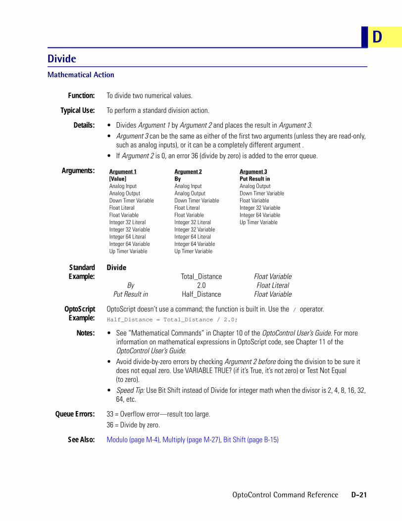
DDivideMathematical Action
Function: To divide two numerical values.
Typical Use: To perform a standard division action.
Details: • Divides Argument 1 by Argument 2 and places the result in Argument 3.• Argument 3 can be the same as either of the first two arguments (unless they are read-only,
such as analog inputs), or it can be a completely different argument .• If Argument 2 is 0, an error 36 (divide by zero) is added to the error queue.
Arguments:
StandardExample:
DivideTotal_Distance Float Variable
By 2.0 Float LiteralPut Result in Half_Distance Float Variable
OptoScriptExample:
OptoScript doesn’t use a command; the function is built in. Use the / operator.Half_Distance = Total_Distance / 2.0;
Notes: • See “Mathematical Commands” in Chapter 10 of the OptoControl User’s Guide. For more information on mathematical expressions in OptoScript code, see Chapter 11 of the OptoControl User’s Guide.
• Avoid divide-by-zero errors by checking Argument 2 before doing the division to be sure it does not equal zero. Use VARIABLE TRUE? (if it’s True, it’s not zero) or Test Not Equal (to zero).
• Speed Tip: Use Bit Shift instead of Divide for integer math when the divisor is 2, 4, 8, 16, 32, 64, etc.
Queue Errors: 33 = Overflow error—result too large.36 = Divide by zero.
See Also: Modulo (page M-4), Multiply (page M-27), Bit Shift (page B-15)
Argument 1[Value]Analog InputAnalog OutputDown Timer VariableFloat LiteralFloat VariableInteger 32 LiteralInteger 32 VariableInteger 64 LiteralInteger 64 VariableUp Timer Variable
Argument 2ByAnalog InputAnalog OutputDown Timer VariableFloat LiteralFloat VariableInteger 32 LiteralInteger 32 VariableInteger 64 LiteralInteger 64 VariableUp Timer Variable
Argument 3Put Result inAnalog OutputDown Timer VariableFloat VariableInteger 32 VariableInteger 64 VariableUp Timer Variable
OptoControl Command Reference D-21

Down Timer Expired?Miscellaneous Condition
Function: To check if a down timer has expired (reached zero).
Typical Use: Used to measure a time interval with good precision. Better than time delay commands for delays within looping charts.
Details: When a down timer has reached zero, it is considered expired.
Arguments:
StandardExample:
Down Timer Expired?Down Timer OVEN_TIMER Down Timer Variable
OptoScriptExample:
HasDownTimerExpired(Down Timer)if (HasDownTimerExpired(OVEN_TIMER)) then
This is a function command; it returns a value of true (non-zero) or false (0). The returned value can be consumed by a control structure (as in the example shown) or by a variable, I/O point, etc. See Chapter 11 of the OptoControl User’s Guide for more information.
Notes: See “Miscellaneous Commands” in Chapter 10 of the OptoControl User’s Guide for more information on using timer commands.
See Also: Start Timer (page S-62), Stop Timer (page S-68), Continue Timer (page C-45), Pause Timer (page P-1), Set Down Timer Preset Value (page S-19)
Argument 1Down TimerDown Timer Variable
D-22 OptoControl Command Reference

E
EEnable Communication to All I/O PointsSimulation ActionFunction: To enable communication between the program in the controller and all analog and digital points.
Typical Use: To re-connect the program to all analog and digital points after simulation and testing.
Details: All analog and digital point communication is enabled by default.
Arguments: None
StandardExample:
Enable Communication to All I/O Points
OptoScriptExample:
EnableCommunicationToAllIoPoints()EnableCommunicationToAllIoPoints();
This is a procedure command; it does not return a value.
See Also: Disable Communication to All I/O Points (page D-4), I/O Point Communication Enabled? (page I-7)
OptoControl Command Reference E-1

Enable Communication to All I/O UnitsSimulation Action
Function: Changes a flag internal to the controller to indicate that all the I/O units are online. This allows normal communication from the program to the I/O units.
Typical Use: To cause the program in the controller to attempt to read/write to I/O units (XVALs) rather than use internal values (IVALs). Very useful to re-establish communication with all I/O units that have just been turned on without having to specify their name.
Details: Sets the Enabled flag which allows the next program reference to the I/O unit to attempt to communicate with the I/O unit. If the I/O unit has just been turned on, it will be configured. If a watchdog at the I/O unit timed out while communication was disabled, a watchdog timeout error will be added to the error queue.
Arguments: None.
StandardExample:
Enable Communication to All I/O Units
OptoScriptExample:
EnableCommunicationToAllIoUnits()EnableCommunicationToAllIoUnits();
This is a procedure command; it does not return a value.
Notes: • Can be used in a chart that executes periodically to automatically bring I/O units that have just been turned on back online.
• Use of this command periodically within a program will prevent the disabling of communication to any point or any I/O unit by any means.
See Also: Disable Communication to All I/O Units (page D-5)
E-2 OptoControl Command Reference

EEnable Communication to Analog PointSimulation Action
Function: To enable communication between the program in the controller and an individual analog channel.
Typical Use: To reconnect the program to a specified analog channel after simulation or program testing.
Details: • All analog channel communication is enabled by default.• This command does not affect the analog channel in any way. It only connects the program
in the controller with the analog channel.• When communication to an analog channel is enabled, program actions again take effect.• When a program reads the value of an enabled input channel, the current value of the
channel (XVAL) will be returned to the program (IVAL). Likewise, an enabled output channel will update when the program writes a value. The XVAL and IVAL will match at this time.
Arguments:
StandardExample:
Enable Communication to Analog PointTANK_LEVEL Analog Input
OptoScriptExample:
EnableCommunicationToAnalogPoint(Point)EnableCommunicationToAnalogPoint(TANK_LEVEL);
This is a procedure command; it does not return a value.
Notes: Use this command to enable an analog channel previously disabled by the Disable Communication to Analog Point command.
See Also: Disable Communication to Analog Point (page D-6)
Argument 1[Value]Analog InputAnalog Output
OptoControl Command Reference E-3

Enable Communication to Digital PointSimulation Action
Function: To enable communication between the program in the controller and an individual digital channel.
Typical Use: To reconnect the program to a specified digital channel after simulation or program testing.
Details: • All digital channel communication is enabled by default.• This command does not affect the digital channel in any way. It only connects the program in
the controller with the digital channel.• When communication to a digital channel is enabled, program actions can affect it.• When a program reads the state of an enabled input channel, the current status of the
channel (XVAL) will be returned to the program (IVAL).• Likewise, an enabled output channel will update when the program writes a value. The
XVAL and IVAL will match at this time.
Arguments:
StandardExample:
Enable Communication to Digital PointMotor_Start Local Simple Digital Output
OptoScriptExample:
EnableCommunicationToDigitalPoint(Point)EnableCommunicationToDigitalPoint(Motor_Start);
This is a procedure command; it does not return a value.
Notes: • Use Turn On instead to turn on digital output.• Use this command to enable a digital channel previously disabled by the Disable
Communication to Digital Point command.
See Also: Disable Communication to Digital Point (page D-7)
Argument 1[Value]Digital InputDigital OutputLocal Simple Digital InputLocal Simple Digital Output
E-4 OptoControl Command Reference

EEnable Communication to Event/ReactionSimulation Action
Function: To enable communication between the program in the controller and the specified event/reaction.
Typical Use: To reconnect the program to a specified event/reaction after simulation and program testing.
Details: • All event/reaction communication is enabled by default.• Does not affect the event/reaction at the I/O unit in any way.
Arguments:
StandardExample:
Enable Communication to Event/ReactionESTOP_BUTTON_1 Analog Event/Reaction
OptoScriptExample:
EnableCommunicationToEventReaction(Event/Reaction)EnableCommunicationToEventReaction(ESTOP_BUTTON_1);
This is a procedure command; it does not return a value.
Notes: • See “Event/Reaction Commands” in Chapter 10 of the OptoControl User’s Guide.• To enable all event/reactions, use Enable Scanning for All Events.
Dependencies: • Event/reactions must be named and configured on the I/O unit before they can be referenced.
• Event/reactions are not supported on local simple I/O units.
See Also: Disable Communication to Event/Reaction (page D-8), Enable Scanning for All Events (page E-14)
Argument 1[Value]Analog Event/ReactionDigital Event/Reaction
OptoControl Command Reference E-5

Enable Communication to I/O UnitSimulation Action
Function: To enable communication between the program in the controller and all channels on the I/O unit.
Typical Use: To re-establish communication between the controller and the I/O unit after it was automatically disabled due to a timeout error (29).
Details: • Attempts to communicate with the I/O unit.• If the communication succeeds and the I/O unit reports that it has lost power since the last
communication, all channels will be configured and all event/reactions (if any) will be sent. Counters will have to be restarted under program control.
• If this command fails because the I/O unit specified is still not responding, a new error 29 will be added to the bottom of the error queue.
Arguments:
StandardExample:
Enable Communication to I/O UnitVapor_Extraction G4 Digital Multifunction I/O Unit
OptoScriptExample:
EnableCommunicationToIoUnit(I/O Unit)EnableCommunicationToIoUnit(Vapor_Extraction);
This is a procedure command; it does not return a value.
Notes: This command is sometimes useful for debugging and/or system startup.
Queue Errors: 29 = I/O unit did not respond within specified time.
See Also: Disable Communication to I/O Unit (page D-9)
Argument 1[Value]B100 Digital Multifunction I/O UnitB200 Analog Multifunction I/O UnitB3000 SNAP AnalogB3000 SNAP DigitalB3000 SNAP Mixed I/OG4 Analog Multifunction I/O UnitG4 Digital Local Simple I/O UnitG4 Digital Multifunction I/O UnitG4 Digital Remote Simple I/O UnitHRD Analog Current Output I/O UnitHRD Analog RTD Input I/O UnitHRD Analog Thermocouple/mV Input I/O UnitHRD Analog Voltage Output I/O UnitHRD Analog Voltage/Current Input I/O UnitSNAP Digital 64SNAP Remote Simple Digital
E-6 OptoControl Command Reference
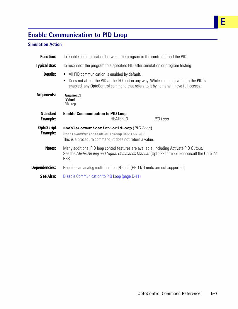
EEnable Communication to PID LoopSimulation Action
Function: To enable communication between the program in the controller and the PID.
Typical Use: To reconnect the program to a specified PID after simulation or program testing.
Details: • All PID communication is enabled by default.• Does not affect the PID at the I/O unit in any way. While communication to the PID is
enabled, any OptoControl command that refers to it by name will have full access.
Arguments:
StandardExample:
Enable Communication to PID LoopHEATER_3 PID Loop
OptoScriptExample:
EnableCommunicationToPidLoop(PID Loop)EnableCommunicationToPidLoop(HEATER_3);
This is a procedure command; it does not return a value.
Notes: Many additional PID loop control features are available, including Activate PID Output. See the Mistic Analog and Digital Commands Manual (Opto 22 form 270) or consult the Opto 22 BBS.
Dependencies: Requires an analog multifunction I/O unit (HRD I/O units are not supported).
See Also: Disable Communication to PID Loop (page D-11)
Argument 1[Value]PID Loop
OptoControl Command Reference E-7

Enable Event/Reaction GroupSimulation Action
Function: Changes a flag internal to the controller to indicate that the event/reaction group is online. This allows normal communication from the program to the event/reaction group in the I/O unit.
Typical Use: To re-enable communication from the program in the controller to the event/reaction group in the I/O unit after it was disabled using Disable Event/Reaction Group.
Details: Sets the event/reaction group Enabled flag which allows the next program reference to anything in that group to attempt to communicate with the I/O unit.
Arguments:
StandardExample:
Enable Event/Reaction GroupER_E_STOP_GROUP_A
OptoScriptExample:
EnableEventReactionGroup(E/R Group)EnableEventReactionGroup(ER_E_STOP_GROUP_A);
This is a procedure command; it does not return a value.
Notes: This command has no affect on the operation of the event/reaction group at the I/O unit.
See Also: Disable Event/Reaction Group (page D-12)
Argument 1[Value]Event/Reaction Group
E-8 OptoControl Command Reference

EEnable I/O Unit Causing Current ErrorController Action
Function: To enable communication between the program in the controller and all channels on the I/O unit if the top queue error is a 29.
Typical Use: To re-establish communication between the controller and the I/O unit after it was automatically disabled due to a timeout error (29).
Details: • The controller generates a queue error 29 (timeout) whenever an I/O unit does not respond. When this happens, all further communication to the I/O unit is disabled to ensure that communication to other I/O units does not slow down. This may be undesirable in some cases. This command can be used to re-establish communication.
• If this command fails because the I/O unit specified is still not responding, a new error 29 will be added to the bottom of the error queue.
Arguments: None.
StandardExample:
Enable I/O Unit Causing Current Error
OptoScriptExample:
EnableIoUnitCausingCurrentError()EnableIoUnitCausingCurrentError();
This is a procedure command; it does not return a value.
Notes: • This command is typically used in an error handling chart.• Always use Error on I/O Unit? to determine if the top error in the error queue is an I/O unit
error before using this command.• Always use Remove Current Error and Point to Next Error after using this command.
Dependencies: For this command to have any effect, the top error in the queue must be a 29.
Queue Errors: 29 = I/O unit did not respond within specified time.60 = The current error in the error queue is not an I/O error.
See Also: Disable I/O Unit Causing Current Error (page D-13), Error on I/O Unit? (page E-20)
OptoControl Command Reference E-9

Enable Interrupt on EventEvent/Reaction Action
Function: To activate interrupt notification for a specified event/reaction.
Typical Use: To provide interrupt notification to the Mistic program so it can resume.
Details: The event/reaction must be active (scanning enabled) for the interrupt to work.
Arguments:
StandardExample:
Enable Interrupt on EventEvent/Reaction Acid_Tank_1_High_Level Analog Event/Reaction
OptoScriptExample:
EnableInterruptOnEvent(Event/Reaction)EnableInterruptOnEvent(Acid_Tank_1_High_Level);
This is a procedure command; it does not return a value.
Notes: • See “Event/Reaction Commands” in Chapter 10 of the OptoControl User’s Guide.• Use Enable Communication to Event/Reaction to enable a disabled event/reaction.
Dependencies: • Event/reactions must be configured on the I/O unit before they can be referenced.• Event/reactions are not supported on simple I/O units.
See Also: Disable Interrupt on Event (page D-14), Disable Scanning for Event (page D-19)
Argument 1Event/ReactionAnalog Event/ReactionDigital Event/Reaction
E-10 OptoControl Command Reference

EEnable PID OutputPID Action
Function: To enable the PID to update its associated analog output channel.
Typical Use: To reconnect the PID with its associated analog output channel after manual changes were made to the analog output channel via program or debugger.
Details: • A manually set output value will remain unchanged until it is either changed again manually or the PID output is enabled. When the PID output is enabled, any necessary output adjustments will be made to the current value. This is a bumpless operation.
• Sets bit 5 of the PID control word.• This command is not for use with SNAP Ethernet I/O or the SNAP-PID-V module.
Arguments:
StandardExample:
Enable PID OutputOn PID Loop EXTRUDER_ZONE08 PID Loop
OptoScriptExample:
EnablePidOutput(On PID Loop)EnablePidOutput(EXTRUDER_ZONE08);
This is a procedure command; it does not return a value.
Notes: The PID calculation is ongoing while the PID output is “disabled.” The PID has no knowledge that its connection to the associated analog output channel has been disconnected.
See Also: Disable PID Output (page D-15)
Argument 1On PID LoopPID Loop
OptoControl Command Reference E-11

Enable PID Output Tracking in Manual ModePID Action
Function: To cause the PID output to track the PID input while in manual mode.
Typical Use: As a non-PID related signal converter.
Details: • Factory default is PID output tracking disabled.• When PID output tracking is enabled the PID output will track the input while in manual
mode. This is useful as a signal converter where the input is a temperature sensor for example and the output is 0–10 volts.
• Sets bit 4 of the PID control word.• This command is not for use with SNAP Ethernet I/O or the SNAP-PID-V module.
Arguments:
StandardExample:
Enable PID Output Tracking in Manual ModeOn PID Loop EXTRUDER_ZONE08 PID Loop
OptoScriptExample:
EnablePidOutputTrackingInManualMode(On PID Loop)EnablePidOutputTrackingInManualMode(EXTRUDER_ZONE08);
This is a procedure command; it does not return a value.
Notes: • This command is best used in the Powerup chart.• The effects of this command can be stored at the I/O unit permanently by using Write I/O
Unit Configuration to EEPROM.
See Also: Disable PID Output Tracking in Manual Mode (page D-16), Write I/O Unit Configuration to EEPROM (page W-5)
Argument 1On PID LoopPID Loop
E-12 OptoControl Command Reference

EEnable PID Setpoint Tracking in Manual ModePID Action
Function: To cause the PID setpoint to track the PID input while in manual mode.
Typical Use: To prevent a “bump” on the PID output when switching from manual to auto mode.
Details: • Factory default is PID setpoint tracking enabled.• When PID setpoint tracking is enabled the setpoint will follow the PID input to ensure zero
error. Therefore, when switching from manual to auto, the PID output will not change. This is called a “bumpless transfer.”
• This may not be the most desirable state because the setpoint is altered, which means the setpoint must be changed back to where it was, which will cause a bump in the PID output.
• Sets bit 3 of the PID control word.• This command is not for use with SNAP Ethernet I/O or the SNAP-PID-V module.
Arguments:
StandardExample:
Enable PID Setpoint Tracking in Manual ModeOn PID Loop EXTRUDER_ZONE08 PID Loop
OptoScriptExample:
EnablePidSetpointTrackingInManualMode(On PID Loop)EnablePidSetpointTrackingInManualMode(EXTRUDER_ZONE08);
This is a procedure command; it does not return a value.
Notes: • This command is best used in the Powerup chart.• The effects of this command can be stored at the I/O unit permanently by using Write I/O
Unit Configuration to EEPROM.
See Also: Disable PID Setpoint Tracking in Manual Mode (page D-17), Write I/O Unit Configuration to EEPROM (page W-5)
Argument 1On PID LoopPID Loop
OptoControl Command Reference E-13

Enable Scanning for All EventsEvent/Reaction Action
Function: To activate all event/reactions on the specified I/O unit.
Typical Use: To reactivate all event/reactions after a planned shutdown or an emergency stop.
Details: Whenever scanning for event/reactions is started, all events found to be True on the first scan will be considered to have just occurred. Therefore, the reactions will follow.
Arguments:
StandardExample:
Enable Scanning for All EventsOn I/O Unit Overtemp_Sensors G4 Digital Multifunction I/O Unit
OptoScriptExample:
EnableScanningForAllEvents(On I/O Unit)EnableScanningForAllEvents(Overtemp_Sensors);
This is a procedure command; it does not return a value.
Notes: • See “Event/Reaction Commands” in Chapter 10 of the OptoControl User’s Guide.• To activate a specific event/reaction, use Enable Scanning for Event.• Normally used after Disable Scanning for All Events.
Dependencies: Event/reactions are not supported on simple I/O units.
See Also: Disable Scanning for Event (page D-19), Enable Scanning for Event (page E-15), Disable Scanning for All Events (page D-18)
Argument 1On I/O UnitB100 Digital Multifunction I/O UnitB200 Analog Multifunction I/O UnitB3000 SNAP AnalogB3000 SNAP DigitalG4 Analog Multifunction I/O UnitG4 Digital Multifunction I/O UnitHRD Analog Current Output I/O UnitHRD Analog RTD Input I/O UnitHRD Analog Thermocouple/mV Input I/O UnitHRD Analog Voltage Output I/O UnitHRD Analog Voltage/Current Input I/O Unit
E-14 OptoControl Command Reference

EEnable Scanning for EventEvent/Reaction Action
Function: To activate a specific event/reaction.
Typical Use: To reactivate a specific event/reaction after a planned shutdown.
Details: If the event is found to be True when scanning for an event/reaction is started, the reaction will occur.
Arguments:
StandardExample:
Enable Scanning for EventEvent/Reaction Acid_Tank_1_High_Level Digital Event/Reaction
OptoScriptExample:
EnableScanningForEvent(Event/Reaction)EnableScanningForEvent(Acid_Tank_1_High_Level);
This is a procedure command; it does not return a value.
Notes: • See “Event/Reaction Commands” in Chapter 10 of the OptoControl User’s Guide.• To activate all event/reactions, use Enable Scanning for All Events.
Dependencies: • Event/reactions must be named and configured on the I/O unit before they can be referenced.
• Event/reactions are not supported on simple I/O units.
See Also: Enable Scanning for All Events (page E-14)
Argument 1Event/ReactionAnalog Event/ReactionDigital Event/Reaction
OptoControl Command Reference E-15

Enable Scanning of Event/Reaction GroupEvent/Reaction Action
Function: Starts all event/reactions in the specified group.
Typical Use: To start scanning all event/reactions in the specified group with one command rather than issuing a separate command to start each one.
Details: There can be up to 16 event/reaction groups, each containing as many as 16 event/reactions. If all related event/reactions are in the same group, this command could be quite useful.
Arguments:
StandardExample:
Enable Scanning of Event/Reaction GroupEvent/Reaction Group ER_E_STOP_GROUP_A
OptoScriptExample:
EnableScanningOfEventReactionGroup()EnableScanningOfEventReactionGroup(ER_E_STOP_GROUP_A);
This is a procedure command; it does not return a value.
See Also: Disable Scanning of Event/Reaction Group (page D-20)
Equal?Logical Condition
Function: To determine the equality of two values.
Typical Use: To branch program logic based on the sequence number of the process.
Details: • Determines if Argument 1 is equal to Argument 2. Examples:Argument 1 Argument 2 Result
-1 -1 True-1 1 False
22.22 22.22 True22.22 22.221 False
• Evaluates True if both values are the same, False otherwise.
Argument 1Event/Reaction GroupEvent/Reaction Group
E-16 OptoControl Command Reference
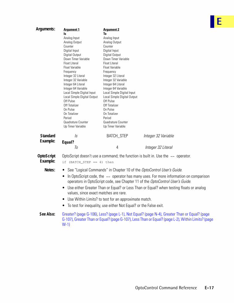
EArguments:
StandardExample:
Is BATCH_STEP Integer 32 VariableEqual?
To 4 Integer 32 Literal
OptoScriptExample:
OptoScript doesn’t use a command; the function is built in. Use the == operator.if (BATCH_STEP == 4) then
Notes: • See “Logical Commands” in Chapter 10 of the OptoControl User’s Guide.• In OptoScript code, the == operator has many uses. For more information on comparison
operators in OptoScript code, see Chapter 11 of the OptoControl User’s Guide.• Use either Greater Than or Equal? or Less Than or Equal? when testing floats or analog
values, since exact matches are rare.• Use Within Limits? to test for an approximate match.• To test for inequality, use either Not Equal? or the False exit.
See Also: Greater? (page G-106), Less? (page L-1), Not Equal? (page N-4), Greater Than or Equal? (page G-107), Greater Than or Equal? (page G-107), Less Than or Equal? (page L-2), Within Limits? (page W-1)
Argument 1IsAnalog InputAnalog OutputCounterDigital InputDigital OutputDown Timer VariableFloat LiteralFloat VariableFrequencyInteger 32 LiteralInteger 32 VariableInteger 64 LiteralInteger 64 VariableLocal Simple Digital InputLocal Simple Digital OutputOff PulseOff TotalizerOn PulseOn TotalizerPeriodQuadrature CounterUp Timer Variable
Argument 2ToAnalog InputAnalog OutputCounterDigital InputDigital OutputDown Timer VariableFloat LiteralFloat VariableFrequencyInteger 32 LiteralInteger 32 VariableInteger 64 LiteralInteger 64 VariableLocal Simple Digital InputLocal Simple Digital OutputOff PulseOff TotalizerOn PulseOn TotalizerPeriodQuadrature CounterUp Timer Variable
OptoControl Command Reference E-17
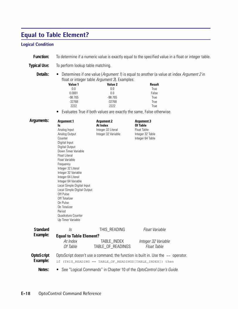
Equal to Table Element?Logical Condition
Function: To determine if a numeric value is exactly equal to the specified value in a float or integer table.
Typical Use: To perform lookup table matching.
Details: • Determines if one value (Argument 1) is equal to another (a value at index Argument 2 in float or integer table Argument 3). Examples:
Value 1 Value 2 Result0.0 0.0 True
0.0001 0.0 False-98.765 -98.765 True-32768 -32768 True2222 2222 True
• Evaluates True if both values are exactly the same, False otherwise.
Arguments:
StandardExample:
Is THIS_READING Float VariableEqual to Table Element?
At Index TABLE_INDEX Integer 32 VariableOf Table TABLE_OF_READINGS Float Table
OptoScriptExample:
OptoScript doesn’t use a command; the function is built in. Use the == operator.if (THIS_READING == TABLE_OF_READINGS[TABLE_INDEX]) then
Notes: • See “Logical Commands” in Chapter 10 of the OptoControl User’s Guide.
Argument 1IsAnalog InputAnalog OutputCounterDigital InputDigital OutputDown Timer VariableFloat LiteralFloat VariableFrequencyInteger 32 LiteralInteger 32 VariableInteger 64 LiteralInteger 64 VariableLocal Simple Digital InputLocal Simple Digital OutputOff PulseOff TotalizerOn PulseOn TotalizerPeriodQuadrature CounterUp Timer Variable
Argument 2At IndexInteger 32 LiteralInteger 32 Variable
Argument 3Of TableFloat TableInteger 32 TableInteger 64 Table
E-18 OptoControl Command Reference

E• In OptoScript code, the == operator has many uses. For more information on comparison
operators in OptoScript code, see Chapter 11 of the OptoControl User’s Guide.• Use either Greater Than or Equal to Table Element? or Less Than Or Equal To Table Element?
when testing floats, integers, or analog values unless an exact match is required.• To test for inequality, use either Not Equal to Table Element? or the False exit.
Queue Errors: 32 = Bad table index value—index was negative or greater than the table size.
See Also: Greater Than Table Element? (page G-109), Less Than Table Element? (page L-5), Not Equal to Table Element? (page N-5), Greater Than or Equal to Table Element? (page G-108), Less Than or Equal to Table Element? (page L-3)
Error?Controller Condition
Function: To determine if there is an error in the error queue.
Typical Use: To determine if further error handling should be performed.
Details: Evaluates True if there is an error in the error queue, False otherwise.
Arguments: None.
StandardExample:
Error?
OptoScriptExample:
IsErrorPresent()if (IsErrorPresent()) then
This is a function command; it returns a value of true (non-zero) or false (0). The returned value can be consumed by a control structure (as in the example shown) or by a variable, I/O point, etc. See Chapter 11 of the OptoControl User’s Guide for more information.
Notes: • Use Error on I/O Unit? to determine if it is an I/O related error.• Use Debug mode to view the error queue for detailed information.
See Also: Error on I/O Unit? (page E-20)
OptoControl Command Reference E-19

Error on I/O Unit?Controller Condition
Function: To determine if the top error in the error queue is an I/O-related error.
Typical Use: To determine if further error handling for I/O units should be performed.
Details: • Evaluates True if the current error in the error queue is an I/O unit error, False otherwise.• Queue errors two through 29 are considered I/O unit errors, with 29 being the most common.
Arguments: None.
StandardExample:
Error on I/O Unit?
OptoScriptExample:
IsErrorOnIoUnit()if (IsErrorOnioUnit()) then
This is a function command; it returns a value of true (non-zero) or false (0). The returned value can be consumed by a control structure (as in the example shown) or by a variable, I/O point, etc. See Chapter 11 of the OptoControl User’s Guide for more information.
Notes: Use Caused an I/O Unit Error? to determine which I/O unit caused the error.
Queue Errors: Use Debug mode to view the error queue for detailed information.
See Also: Caused an I/O Unit Error? (page C-11), Remove Current Error and Point to Next Error (page R-26), Error? (page E-19)
E-20 OptoControl Command Reference

EEthernet Session Open?Communication—Network Condition
Function: To determine if the specified Ethernet session is still online.
Typical Use: To determine if the other node associated with the Ethernet session number is still online.
Details: Evaluates True if the Ethernet session is online.
Arguments:
StandardExample:
Session SESSION_NUMBER Integer 32 VariableEthernet Session Open?
OptoScriptExample:
IsEnetSessionOpen(Session)if (IsEnetSessionOpen(SESSION_NUMBER)) then
This is a function command; it returns a value of true (non-zero) or false (0). The returned value can be consumed by a control structure (as in the example shown) or by a variable, I/O point, etc. See Chapter 11 of the OptoControl User’s Guide for more information.
Notes: An Ethernet session is a logical link (a virtual dedicated cable) between two nodes. Up to 32 sessions total can be concurrently established on the three logical Ethernet ports—8, 9, and 10. These three ports use the same Ethernet card.
Dependencies: Must first use Open Ethernet Session to establish a session, or Accept Session on TCP Port to accept a session initiated by a peer.
See Also: Open Ethernet Session (page O-5)
Argument 1SessionInteger 32 LiteralInteger 32 Variable
OptoControl Command Reference E-21

Event Occurred?Event/Reaction Condition
Function: To determine if a specific event has occurred.
Typical Use: To determine which event caused an interrupt.
Details: • Evaluates True if the specified event/reaction has occurred, False if it has not.• When the event occurs, its event latch is set. It will remain set until cleared with Clear Event
Latch.
Arguments:
StandardExample:
Has Sequence_Finished Analog Event/ReactionEvent Occurred?
OptoScriptExample:
HasEventOccurred(Event/Reaction)if (HasEventOccurred(Sequence_Finished)) then
This is a function command; it returns a value of true (non-zero) or false (0). The returned value can be consumed by a control structure (as in the example shown) or by a variable, I/O point, etc. See Chapter 11 of the OptoControl User’s Guide for more information.
Notes: • See “Event/Reaction Commands” in Chapter 10 of the OptoControl User’s Guide.• The current state of the event is not relevant to this condition. See Event Occurring?• Always use Clear Event Latch after the event has occurred. This allows detection of
subsequent events.
Dependencies: • Event/reactions must be named and configured on the I/O unit before they can be referenced.
• Event/reactions are not supported on local simple I/O units.
See Also: Event Occurring? (page E-23) Clear Event Latch (page C-26), Clear I/O Unit Interrupt (page C-27), Generating Interrupt? (page G-9)
Argument 1HasAnalog Event/ReactionDigital Event/Reaction
E-22 OptoControl Command Reference
EEvent Occurring?Event/Reaction Condition
Function: To determine if the criteria for a specific event is currently true.
Typical Use: To determine if a specific situation still exists.
Details: Evaluates True if the criteria for the specified event are still true, False if the criteria are no longer true.
Arguments:
StandardExample:
Is Sequence_Finished Analog Event/ReactionEvent Occurring?
OptoScriptExample:
IsEventOccurring(Event/Reaction)if (IsEventOccurring(Sequence_Finished)) then
This is a function command; it returns a value of true (non-zero) or false (0). The returned value can be consumed by a control structure (as in the example shown) or by a variable, I/O point, etc. See Chapter 11 of the OptoControl User’s Guide for more information.
Notes: • See “Event/Reaction Commands” in Chapter 10 of the OptoControl User’s Guide.• This is an easy way to test for an I/O state pattern.
Dependencies: • Event/reactions must be named and configured on the I/O unit before they can be referenced.
• Event/reactions are not supported on local simple I/O units.
See Also: Event Occurred? (page E-22)
Argument 1IsAnalog Event/ReactionDigital Event/Reaction
OptoControl Command Reference E-23

Event/Reaction Communication Enabled?Simulation Condition
Function: Checks a flag internal to the controller to determine if communication to the specified event/reaction is enabled.
Typical Use: Primarily used in factory QA testing and simulation.
Details: Evaluates True if communication is enabled.
Arguments:
StandardExample:
Event/Reaction ER_E_STOP_1Event/Reaction Communication Enabled?
OptoScriptExample:
IsEventReactionCommEnabled(Event/Reaction)if (IsEventReactionCommEnabled(ER_E_STOP_1)) then
This is a function command; it returns a value of true (non-zero) or false (0). The returned value can be consumed by a control structure (as in the example shown) or by a variable, I/O point, etc. See Chapter 11 of the OptoControl User’s Guide for more information.
See Also: Event/Reaction Group Communication Enabled? (page E-25)
Argument 1Event/ReactionAnalog Event/ReactionDigital Event/Reaction
E-24 OptoControl Command Reference

EEvent/Reaction Group Communication Enabled?Simulation Condition
Function: Checks a flag internal to the controller to determine if communication to the specified event/reaction group is enabled.
Typical Use: Primarily used in factory QA testing and simulation.
Details: Evaluates True if communication is enabled.
Arguments:
StandardExample:
E/R Group ER_E_STOP_GROUPEvent/Reaction Group Communication Enabled?
OptoScriptExample:
IsEventReactionGroupEnabled(E/R Group)if (IsEventReactionGroupEnabled(ER_E-STOP_GROUP)) then
This is a function command; it returns a value of true (non-zero) or false (0). The returned value can be consumed by a control structure (as in the example shown) or by a variable, I/O point, etc. See Chapter 11 of the OptoControl User’s Guide for more information.
See Also: Event/Reaction Communication Enabled? (page E-24)
Argument 1E/R GroupEvent/Reaction Group
OptoControl Command Reference E-25

Event Scanning Disabled? Event/Reaction Condition
Function: To determine if a specific event/reaction is active or not.
Typical Use: To verify the active/inactive state of a specific event/reaction.
Details: Evaluates True if the specified event/reaction is not being scanned, False if it is being scanned.
Arguments:
StandardExample:
Event/Reaction Sequence_FinishedEvent Scanning Disabled?
OptoScriptExample:
IsEventScanningDisabled(Event/Reaction)if (IsEventScanningDisabled(Sequence_Finished)) then
This is a function command; it returns a value of true (non-zero) or false (0). The returned value can be consumed by a control structure (as in the example shown) or by a variable, I/O point, etc. See Chapter 11 of the OptoControl User’s Guide for more information.
Dependencies: • Event/reactions must be named and configured on the I/O unit before they can be referenced.
• Event/reactions are not supported on local simple I/O units.
Notes: See “Event/Reaction Commands” in Chapter 10 of the OptoControl User’s Guide.
See Also: Event Scanning Enabled? (page E-27)
Argument 1Event/ReactionAnalog Event/ReactionDigital Event/Reaction
E-26 OptoControl Command Reference

EEvent Scanning Enabled?Event/Reaction Condition
Function: To determine if a specific event/reaction is active.
Typical Use: To verify the active/inactive state of a specific event/reaction.
Details: Evaluates True if the specified event/reaction is being scanned, False if it’s not being scanned.
Arguments:
StandardExample:
Event/Reaction Sequence_FinishedEvent Scanning Enabled?
OptoScriptExample:
IsEventScanningEnabled(Event/Reaction)if (IsEventScanningEnabled(Sequence_Finished)) then
This is a function command; it returns a value of true (non-zero) or false (0). The returned value can be consumed by a control structure (as in the example shown) or by a variable, I/O point, etc. See Chapter 11 of the OptoControl User’s Guide for more information.
Notes: See “Event/Reaction Commands” in Chapter 10 of the OptoControl User’s Guide.
Dependencies: • Event/reactions must be named and configured on the I/O unit before they can be referenced.
• Event/reactions are not supported on local simple I/O units.
See Also: Event Scanning Disabled? (page E-26)
Argument 1Event/ReactionAnalog Event/ReactionDigital Event/Reaction
OptoControl Command Reference E-27

E-28 OptoControl Command Reference

F
FFind Character in StringString ActionFunction: Locate a character within a string.
Typical Use: When parsing strings to locate delimiters and punctuation characters.
Details: • The search is case-sensitive.• The search begins at the location specified so that multiple occurrences of the same
character can be found.• The last parameter will contain an integer specifying the position at which the character is
located. Values returned will be from 1 to the string length.
Arguments:
StandardExample:
Find Character in StringFind 34 Integer 32 Literal
Start at Index POSITION Integer 32 VariableOf String MSG_RECEIVED String Variable
Put Result in POSITION Integer 32 Variable
OptoScriptExample:
FindCharacterInString(Find, Start at Index, Of String)POSITION = FindCharacterInString(34, POSITION, MSG_RECEIVED);
This is a function command; it returns the position at which the character is located in the string.
Notes: When the 2nd and 4th parameters use the same variable, increment the variable after each find so that the same character won’t be found again and again.
Error Code: -80 = Specified character could not be found.
See Also: Find Substring in String (page F-2)
Argument 1FindInteger 32 LiteralInteger 32 Variable
Argument 2Start at IndexInteger 32 LiteralInteger 32 Variable
Argument 3Of StringString LiteralString Variable
Argument 4Put Result inInteger 32 Variable
OptoControl Command Reference F-1

Find Substring in StringString Action
Function: Locate a string of characters (substring) within a string.
Typical Use: When parsing strings to locate key words.
Details: • Quotes (“”) are used in OptoScript code, but not in standard OptoControl code.• The search is case-sensitive.• The search begins at the location specified so that multiple occurrences of the same
substring can be found.• The last parameter will contain an integer specifying the position at which the substring
starts. Values returned will be from 1 to the string length.
Arguments:
StandardExample:
This example shows the string in quotes for clarity only; do not use quotes in the standard command:Find Substring in String
Find “SHIFT” String LiteralStart at Index POSITION Integer 32 Variable
Of String MSG_RECEIVED String VariablePut Result in POSITION Integer 32 Variable
OptoScriptExample:
FindSubstringInString(Find, Start at Index, Of String)POSITION = FindSubstringInString("SHIFT", POSITION, MSG_RECEIVED);
This is a function command; it returns the position at which the substring starts within the string. Quotes are required in OptoScript code.
Notes: When Start At Index and Put Result In use the same variable, increment the variable after each find so that the same substring won’t be found again and again.
Error Code: -81 = Specified substring could not be found.
See Also: Find Character in String (page F-1)
Argument 1FindString LiteralString Variable
Argument 2Start at IndexInteger 32 LiteralInteger 32 Variable
Argument 3Of StringString LiteralString Variable
Argument 4Put Result inInteger 32 Variable
F-2 OptoControl Command Reference

FFloat Valid?Miscellaneous Condition
Function: To verify that a float variable contains a valid value.
Typical Use: To check float validity after reading a float from an external device, such as a comm handle, a scratch pad location, or an analog point.
Details: This command performs a simple test on the float variable to see if it contains a valid IEEE format float number. If the bit pattern of the float value has at least these bits set, 0x7F800000 (01111111100000000000000000000000), then it is considered invalid and the command returns a false (0).
Arguments:
StandardExample:
Float Valid?Is Oil_Pressure Float Variable
OptoScriptExample:
IsFloatValid(Float)if (IsFloatValid(Oil_Pressure)) then
This is a function command; it returns a value of true (non-zero) or false (0). The returned value can be consumed by a control structure (as in the example shown) or by a variable, I/O point, etc. See Chapter 11 of the ioControl User’s Guide for more information.
Notes: Analog points on an unplugged module return a value of NAN (not a number--an invalid float).
See Also: Move 32 Bits (page M-6)
Argument 1IsFloat Variable
OptoControl Command Reference F-3

F-4 OptoControl Command Reference

G
GGenerate Checksum on StringString ActionFunction: Calculate an eight-bit checksum value.
Typical Use: Serial communication that requires checksum error checking.
Details: • Checksum type is eight-bit.• The Start Value is also known as the “seed.” It is usually zero.• When calculating the checksum one character at a time (or a group of characters at a time),
the Start Value must be the result of the calculation on the previous character(s).• The On String can contain as little as one character.
Arguments:
StandardExample:
Generate Checksum on StringStart Value 0 Integer 32 LiteralOn String MSG_TO_SEND String Variable
Put Result in POSITION Integer 32 Variable
OptoScriptExample:
GenerateChecksumOnString(Start Value, On String)POSITION = GenerateChecksumOnString(0, MSG_TO_SEND);
This is a function command; it returns the checksum. The returned value can be consumed by a variable (as shown) or by another item, such as a mathematical expression or a control structure. See Chapter 11 of the OptoControl User’s Guide for more information.
Notes: The checksum can be appended to the string by using the following standard commands:1. “Convert Number to Formatted Hex String” with the length argument set to a value of 2.2. “Append String to String.”
The method used to calculate the checksum is:1. Take the numerical sum of the ASCII numerical representation of each character in the
string.2. Divide the result by 256.3. The integer remainder is the eight-bit checksum.
To calculate the LRC of a string, take the two’s complement of the checksum:1. Generate checksum on the string.2. Subtract the checksum from 255. This is the one’s complement of the checksum.3. Add one to the result. This is the two’s complement of the checksum.
Argument 1Start ValueInteger 32 LiteralInteger 32 Variable
Argument 2On StringString LiteralString Variable
Argument 3Put Result inInteger 32 Variable
OptoControl Command Reference G-1

Example: For a string containing only the capital letter “A”, the checksum is 65. To calculate the LCR, subtract the checksum (65) from 255, which equals 190. Add one to this result, resulting in an LCR of 191.
See Also: Verify Checksum on String (page V-3)
Generate Forward CCITT on StringString Action
Function: Calculate a 16-bit CRC value.
Typical Use: Serial communication that requires CRC error checking.
Details: • CRC type is 16-bit forward CCITT.• The Start Value is also known as the “seed.” It is usually zero or -1.• When calculating the CRC one character at a time (or a group of characters at a time), the
Start Value must be the result of the calculation on the previous character(s).• The On String can contain as little as one character.
Arguments:
StandardExample:
Generate Forward CCITT on StringStart Value 0 Integer 32 LiteralOn String MSG_TO_SEND String Variable
Put Result in POSITION Integer 32 Variable
OptoScriptExample:
GenerateForwardCcittOnString(Start Value, On String)POSITION = GenerateForwardCcittOnString(0, MSG_TO_SEND);
This is a function command; it returns the forward CCITT. The returned value can be consumed by a variable (as shown) or by another item, such as a mathematical expression or a control structure. See Chapter 11 of the OptoControl User’s Guide for more information.
Notes: The CRC can be appended to the string one character at a time using Append Character to String. For the first character use Bit Shift -8 on the CRC and append the result. For the second character simply append the original CRC value.
Result Data: The “Put Result in” argument will contain the Forward CCITT that was calculated.
See Also: Generate Reverse CCITT on String (page G-6), Generate Forward CRC-16 on String (page G-3), Generate Reverse CRC-16 on Table (32 bit) (page G-8)
Argument 1Start ValueInteger 32 LiteralInteger 32 Variable
Argument 2On StringString LiteralString Variable
Argument 3Put Result inInteger 32 Variable
G-2 OptoControl Command Reference

GGenerate Forward CRC-16 on StringString Action
Function: Calculate a 16-bit CRC value.
Typical Use: Serial communication that requires CRC error checking.
Details: • CRC type is 16-bit forward.• The Start Value is also known as the “seed.” It is usually zero or -1.• When calculating the CRC one character at a time (or a group of characters at a time), the
Start Value must be the result of the calculation on the previous character(s).• The On String can contain as little as one character.
Arguments:
StandardExample:
Generate Forward CRC-16 on StringStart Value 0 Integer 32 LiteralOn String MSG_TO_SEND String Variable
Put Result in POSITION Integer 32 Variable
OptoScriptExample:
GenerateForwardCrc16OnString(Start Value, On String)POSITION = GenerateForwardCrc16OnString(0, MSG_TO_SEND);
This is a function command; it returns the forward CRC. The returned value can be consumed by a variable (as shown) or by another item, such as a mathematical expression or a control structure. See Chapter 11 of the OptoControl User’s Guide for more information.
Notes: The CRC can be appended to the string one character at a time using Append Character to String. For the first character use Bit Shift -8 on the CRC and append the result. For the second character simply append the original CRC value.
See Also: Generate Reverse CRC-16 on String (page G-7), Generate Forward CCITT on String (page G-2), Generate Reverse CRC-16 on Table (32 bit) (page G-8)
Argument 1Start ValueInteger 32 LiteralInteger 32 Variable
Argument 2On StringString LiteralString Variable
Argument 3Put Result inInteger 32 Variable
OptoControl Command Reference G-3

Generate N PulsesDigital Point Action
Function: To output a specified number of pulses of configurable on and off times.
Typical Use: To drive stepper motor controllers, flash indicator lamps, or increment counters.
Details: • Generates a digital waveform on the specified digital output channel. On Time specifies the amount of time in seconds that the channel will remain on during each pulse; Off Time specifies the amount of time the channel will remain off.
• The minimum On Time and Off Time is 0.001 second with a resolution of 0.0001 second, making the maximum frequency 500 Hertz.
• The maximum On Time and Off Time is 429,496.7000 seconds (4.97 days on, 4.97 days off).• Valid range for Number of Pulses is 0 to 2,147,483,647 if an integer is used, 0 to
4,294,967,000 if a float is used.• Not available on SNAP Ethernet brains.
Arguments:
StandardExample:
Generate N PulsesOn Time (Seconds) 0.250 Float LiteralOff Time (Seconds) 0.500 Float LiteralNumber of Pulses Number_of_Pulses Float Variable
On Point DIG_OUTPUT Digital Output
OptoScriptExample:
GenerateNPulses(On Time (Seconds), Off Time (Seconds), Number of Pulses, On Point)GenerateNPulses(0.250, 0.500, Number_of_Pulses, DIG_OUTPUT);
This is a procedure command; it does not return a value.
Notes: • To stop a currently executing pulse train, use Turn Off.• Executing a Generate N Pulses command will discontinue any previous Generate N Pulses
command.• The minimum on or off time is 0.001 seconds; however, the digital output module’s minimum
turn-on and turn-off times may be greater. Check the specifications for the module to be used.
Dependencies: Applies only to outputs on digital multifunction I/O units.
See Also: Turn Off (page T-37), Start Continuous Square Wave (page S-54)
Argument 1On Time (Seconds)Float LiteralFloat VariableInteger 32 LiteralInteger 32 Variable
Argument 2Off Time (Seconds)Float LiteralFloat VariableInteger 32 LiteralInteger 32 Variable
Argument 3Number of PulsesFloat LiteralFloat VariableInteger 32 LiteralInteger 32 Variable
Argument 4On PointDigital Output
G-4 OptoControl Command Reference
GGenerate Random NumberMathematical Action
Function: To get a random value between zero and one.
Typical Use: To generate random delay values for retries when multiple clients are requesting the same resource.
Details: Use Seed Random Number before using this command to give the random number generator a random value to start with. Since the sequence of “random” numbers generated for any given seed value is always the same, it is imperative that a random seed value be used to avoid generating the same sequence of numbers every time.
Arguments:
StandardExample:
Generate Random NumberPut in LOTTO_SEED Float Variable
OptoScriptExample:
GenerateRandomNumber()LOTTO_SEED = GenerateRandomNumber();
This is a function command; it returns the random number. The returned value can be consumed by a variable (as shown) or by another item, such as a mathematical expression or a control structure. See Chapter 11 of the OptoControl User’s Guide for more information.
Notes: To get a random Integer between zero and 99, for example, multiply the float value returned by 99.0 and put the result in an integer.
Dependencies: Use Seed Random Number first.
See Also: Seed Random Number (page S-1)
Argument 1Put inFloat Variable
OptoControl Command Reference G-5

Generate Reverse CCITT on StringString Action
Function: Calculate a 16-bit CRC value.
Typical Use: Serial communication that requires CRC error checking.
Details: • CRC type is 16-bit reverse CCITT.• The Start Value is also known as the “seed.” It is usually zero or -1.• When calculating the CRC one character at a time (or a group of characters at a time), the
Start Value must be the result of the calculation on the previous character(s).• The On String can contain as little as one character.
Arguments:
StandardExample:
Generate Reverse CCITT on StringStart Value 0 Integer 32 LiteralOn String MSG_TO_SEND String Variable
Put Result in POSITION Integer 32 Variable
OptoScriptExample:
GenerateReverseCcittOnString(Start Value, On String)POSITION = GenerateReversCcittOnString(0, MSG_TO_SEND);
This is a function command; it returns the reverse CCITT. The returned value can be consumed by a variable (as shown) or by another item, such as a mathematical expression or a control structure. See Chapter 11 of the OptoControl User’s Guide for more information.
Notes: The CRC can be appended to the string one character at a time using Append Character to String. For the first character use Bit Shift -8 on the CRC and append the result. For the second character simply append the original CRC value.
See Also: Generate Forward CCITT on String (page G-2), Generate Reverse CRC-16 on String (page G-7), Generate Reverse CRC-16 on Table (32 bit) (page G-8)
Argument 1Start ValueInteger 32 LiteralInteger 32 Variable
Argument 2On StringString LiteralString Variable
Argument 3Put Result inInteger 32 Variable
G-6 OptoControl Command Reference
GGenerate Reverse CRC-16 on StringString Action
Function: Calculate a 16-bit CRC value.
Typical Use: Serial communication that requires CRC error checking.
Details: • CRC type is 16-bit reverse.• The Start Value is also known as the “seed.” It is usually zero or -1.• When calculating the CRC one character at a time (or a group of characters at a time), the
Start Value must be the result of the calculation on the previous character(s).• The On String can contain as little as one character.
Arguments:
StandardExample:
Generate Reverse CRC-16 on StringStart Value 0 Integer 32 LiteralOn String MSG_TO _SEND String Variable
Put Result in POSITION Integer 32 Variable
OptoScriptExample:
GenerateReverseCrc16OnString(Start Value, On String)POSITION = GenerateReverseCrc16OnString(0, MSG_TO_SEND);
This is a function command; it returns the CRC. The returned value can be consumed by a variable (as shown) or by another item, such as a mathematical expression or a control structure. See Chapter 11 of the OptoControl User’s Guide for more information.
Notes: The CRC can be appended to the string one character at a time using Append Character to String. For the first character use Bit Shift -8 on the CRC and append the result. For the second character simply append the original CRC value.
See Also: Generate Forward CRC-16 on String (page G-3), Generate Reverse CCITT on String (page G-6), Generate Reverse CRC-16 on Table (32 bit) (page G-8)
Argument 1Start ValueInteger 32 LiteralInteger 32 Variable
Argument 2On StringString LiteralString Variable
Argument 3Put Result inInteger 32 Variable
OptoControl Command Reference G-7

Generate Reverse CRC-16 on Table (32 bit)Miscellaneous Action
Function: Calculate a 16-bit CRC value.
Typical Use: Serial communication that requires CRC error checking. The command is a quick and convenient way to verify the integrity of table data transferrred serially from one controller to another.
Details: • CRC type is 16-bit reverse.• The Start Value is also known as the “seed.” It is usually zero or -1.• The table can contain as little as one element.
Arguments:
StandardExample:
Generate Reverse CRC-16 on Table (32 bit)Start Value 0 Integer 32 Literal
Table VALUES_TO _SEND FloatTableStarting Element 1 Integer 32 LiteralNumber of Elements 31 Integer 32 Literal
Put Result in POSITION Integer 32 Variable
OptoScriptExample:
GenerateReverseCrc16OnTable32(Start Value, Table, Starting Element, Number of Elements)POSITION = GenerateReverseCrc16OnTable32(0, VALUES_TO_SEND, 1, 31);
This is a function command; it returns the CRC. The returned value can be consumed by a variable (as shown) or by another item, such as a mathematical expression or a control structure. See Chapter 11 of the OptoControl User’s Guide for more information.
Notes: • This command is only useful once the data in the table is static. • The easiest way to check data is to make the table one element longer than necessary, then
generate the CRC and move its result to the extra table element. The command Transmit Table via Serial Port is typically used to transfer up to 32 table elements at a time, including the CRC value. When the data is received, use this command at the receiving end to generate the CRC again and compare it to the first CRC value.
For example, on the controller sending the data:
1. Generate Reverse CRC-16 on Table (32 bit) on table elements 1–31.
2. Use Move to Table Element to move the CRC value to table element 0.
3. Use Transmit Table via Serial Port to send all 32 table elements (0–31).
Then, on the controller receiving the data:
1. Receive Table via Serial Port.
2. Generate Reverse CRC-16 on Table (32 bit) on table elements 1–31.
Argument 1Start ValueInteger 32 LiteralInteger 32 Variable
Argument 2TableFloat Table Integer 32 Table
Argument 3Starting ElementInteger 32 LiteralInteger 32 Variable
Argument 4Number of ElementsInteger 32 LiteralInteger 32 Variable
Argument 5Put Result inInteger 32 Variable
G-8 OptoControl Command Reference

G3. Compare the calculated CRC against the value stored in element 0.
• Remember that the maximum size of the table (including the CRC value) is 32 elements.
See Also: Generate Forward CRC-16 on String (page G-3), Generate Reverse CCITT on String (page G-6), Generate Reverse CRC-16 on String (page G-7), Generate Forward CCITT on String (page G-2)
Generating Interrupt?Event/Reaction Condition
Function: To determine if a specific I/O unit is generating an interrupt.
Typical Use: In the Interrupt chart, to determine which I/O unit is generating an interrupt when more than one is configured to do so.
Details: Evaluates True if the specified I/O unit is generating an interrupt, False if it’s not.
Arguments:
StandardExample:
Is OVERTEMP_SENSOR G4 Digital Multifunction I/O UnitGenerating Interrupt?
OptoScriptExample:
IsGeneratingInterrupt(I/O Unit)if (IsGeneratingInterrupt(OVERTEMP_SENSOR)) then
This is a function command; it returns a value of true (non-zero) or false (0). The returned value can be consumed by a control structure (as in the example shown) or by a variable, I/O point, etc. See Chapter 11 of the OptoControl User’s Guide for more information.
Notes: • See “Event/Reaction Commands” in Chapter 10 of the OptoControl User’s Guide.• Use Clear I/O Unit Interrupt immediately after determining the interrupt is on.
Then use Event Occurred? for each event/reaction configured to interrupt.
Dependencies: • Event/reactions must be named and configured on the I/O unit before they can be referenced.
• Event/reactions are not supported on local simple I/O units.
See Also: Event Occurred? (page E-22), Clear I/O Unit Interrupt (page C-27)
Argument 1IsB100 Digital Multifunction I/O UnitB200 Analog Multifunction I/O UnitB3000 SNAP AnalogB3000 SNAP DigitalG4 Analog Multifunction I/O UnitG4 Digital Multifunction I/O UnitHRD Analog Current Output I/O UnitHRD Analog RTD Input I/O UnitHRD Analog Thermocouple/mV Input I/O UnitHRD Analog Voltage Output I/O UnitHRD Analog Voltage/Current Input I/O UnitSNAP Remote Simple Digital
OptoControl Command Reference G-9

Get & Clear Analog Filtered ValueAnalog Point Action
Function: To read a digitally filtered input value from a specified analog channel, then set the filtered value to the current value.
Typical Use: To restart digital filtering using the current value as the default.
Details: • Digital filtering must be activated before using this command by using Set Analog Filter Weight.
• Digital filtering, if activated, is performed at the I/O unit. The analog input point is sampled 10 times a second with the filtered value stored locally on the I/O unit.
• The unfiltered analog input is still available using standard analog commands.• Not available on SNAP Ethernet brains.
Arguments:
StandardExample:
Get & Clear Analog Filtered ValueFrom Temp_Sensor Analog InputPut in Filtered_Temp Float Variable
OptoScriptExample:
GetClearAnalogFilteredValue(From)Filtered_Temp = GetClearAnalogFilteredValue(Temp_Sensor);
This is a function command; it returns the analog filtered value.The returned value can be consumed by a variable (as shown) or by another item, such as a mathematical expression or a control structure. See Chapter 11 of the OptoControl User’s Guide for more information.
Notes: • Do not use this command for frequent reads (one per second or faster) since it continually resets the averaging. Use Get Analog Filtered Value instead.
• To ensure that digital filtering will always be active, store changeable I/O unit values (such as filter weight) in permanent memory at the I/O unit. (You can do so through Debug mode.)
Dependencies: Before using this command, Set Analog Filter Weight must be executed. Otherwise, a value of -32,768 will be returned to indicate an error.
Result Data: Channels without a module installed or with a thermocouple module that has an open thermocouple will return a value of -32,768 to indicate an error.
See Also: Get Analog Filtered Value (page G-30), Set Analog Filter Weight (page S-2)
Argument 1FromAnalog Input
Argument 2Put inFloat VariableInteger 32 Variable
G-10 OptoControl Command Reference

GGet & Clear Analog Maximum ValueAnalog Point Action
Function: To retrieve the peak value of a specified analog input since its last reading, then reset it to the current value.
Typical Use: To capture the peak pressure over a given period of time.
Details: • The current value for each channel is read and stored at the I/O unit every seven milliseconds. However, the response time of the input module may be much slower due to smoothing built into the module. Check the specifications for the module to be used if high-speed readings are required.
• Min and max values are recorded at the I/O unit immediately after the current value is updated.
Arguments:
StandardExample:
Get & Clear Analog Maximum ValueFrom Pres_Sensor Analog InputPut in MAX_KPA Float Variable
OptoScriptExample:
GetClearAnalogMaxValue(From)MAX_KPA = GetClearAnalogMaxValue(Pres_Sensor);
This is a function command; it returns the maximum value of the input since its last reading. The returned value can be consumed by a variable (as shown) or by another item, such as a mathematical expression or a control structure. See Chapter 11 of the OptoControl User’s Guide for more information.
Notes: Use this command to clear the analog max value before actual readings commence.
Dependencies: If digital filtering is active (see Set Analog Filter Weight), min and max value detection is derived from the filtered reading, which is only updated every 100 milliseconds. This could reduce the ability to capture min and max values by several orders of magnitude.
Result Data: • The value returned will be the highest value recorded on this channel since the last time the maximum value was cleared, or since the unit was turned on.
• Channels without a module installed or with a thermocouple module that has an open thermocouple will return a value of -32,768 to indicate an error.
See Also: Get & Clear Analog Minimum Value (page G-12), Get Analog Minimum Value (page G-33), Set Analog Filter Weight (page S-2)
Argument 1FromAnalog Input
Argument 2Put inFloat VariableInteger 32 Variable
OptoControl Command Reference G-11
Get & Clear Analog Minimum ValueAnalog Point Action
Function: To retrieve the lowest value of a specified analog input since its last reading, then reset it to the current value.
Typical Use: To capture the lowest pressure over a given period of time.
Details: • The current value for each channel is read and stored at the I/O unit every seven milliseconds. However, the response time of the input module may be much slower due to smoothing built into the module. Check the specifications for the module to be used if high-speed readings are required.
• Min and max values are recorded at the I/O unit immediately after the current valueis updated.
Arguments:
StandardExample:
Get & Clear Analog Minimum ValueFrom PRES_SENSOR Analog InputPut in MIN_KPA Float Variable
OptoScriptExample:
GetClearAnalogMinValue(From)MIN_KPA = GetClearAnalogMinValue(Pres_Sensor);
This is a function command; it returns the minimum value of the input since its last reading. The returned value can be consumed by a variable (as shown) or by another item, such as a mathematical expression or a control structure. See Chapter 11 of the OptoControl User’s Guide for more information.
Notes: Use this command to clear the analog min value before actual readings commence.
Dependencies: If digital filtering is active (see Set Analog Filter Weight), min and max value detection is derived from the filtered reading, which is only updated every 100 milliseconds. This could reduce the ability to capture min and max values by several orders of magnitude.
Result Data: • The value returned will be the lowest value recorded since the last time the minimum value was reset or since the unit was turned on.
• Channels without a module installed or with a thermocouple module that has an open thermocouple will return a value of -32,768 to indicate an error.
See Also: Get & Clear Analog Maximum Value (page G-11), Get Analog Maximum Value (page G-32), Set Analog Filter Weight (page S-2)
Argument 1FromAnalog Input
Argument 2Put inFloat VariableInteger 32 Variable
G-12 OptoControl Command Reference

GGet & Clear Analog Totalizer ValueAnalog Point Action
Function: To read and clear the totalized (integrated) value of a specified analog input.
Typical Use: To capture a flow total that has been accumulating at the I/O unit before it reaches its maximum value.
Details: • Totalizing is performed at the I/O unit by sampling the input point and storing the total value locally on the I/O unit. This command reads the current total, then clears it to zero.
• The sample rate is set using the Set Analog Totalizer Rate Command.• Totalizing will be bidirectional if the input range is bidirectional, such as -10 to +10.• Totalizing will stop when the total reaches either limit. Totalizing will resume after using
Get & Clear Analog Totalizer Value.• Totalizing will stop when an input channel is too far under range. Totalizing will resume
when the input signal is back within range.• Not available on SNAP Ethernet brains.
Arguments:
StandardExample:
Get & Clear Analog Totalizer ValueFrom Flow_Rate Analog InputPut in Total_Barrels Float Variable
OptoScriptExample:
GetClearAnalogTotalizerValue(From)Total_Barrels = GetClearAnalogTotalizerValue(Flow_Rate);
This is a function command; it returns the totalizer value for the analog input. The returned value can be consumed by a variable (as shown) or by another item, such as a mathematical expression or a control structure. See Chapter 11 of the OptoControl User’s Guide for more information.
Notes: • Before using this command, use Set Analog Totalizer Rate once to establish the sampling rate and start the totalizer. Use this command to clear the total before actual readings start.
• Use Get Analog Totalizer Value periodically to simply “watch” the total. When it exceeds 30,000, use Get & Clear Analog Totalizer Value to capture the total to a float variable and reset it to zero.
• Do not use this command frequently when the total is a small value. Doing so may degrade the cumulative accuracy.
Dependencies: Before using this command, Set Analog Totalizer Rate must be executed. Otherwise, a value of -32,768 will be returned to indicate an error.
Result Data: • The value returned will be an integer from -32,768 to 32,767.• Channels without a module installed will return a value of -32,768 to indicate an error.
See Also: Get Analog Totalizer Value (page G-36), , Set Analog Totalizer Rate (page S-6)
Argument 1FromAnalog Input
Argument 2Put inFloat VariableInteger 32 Variable
OptoControl Command Reference G-13

Get & Clear CounterDigital Point Action
Function: To read and clear a digital input counter value.
Typical Use: To count pulses from turbine flow meters, magnetic pickups, encoders, proximity switches, etc.
Details: • Reads the current value of a digital input counter and places it in the Put In parameter.• Sets the counter at the I/O unit to zero.• Does not stop the counter from continuing to count.• Valid range is 0 to 4,294,967,296 counts.
Arguments:
StandardExample:
Get & Clear CounterFrom Point Bottle_Counter Counter
Put in Number_of_Bottles Integer 32 Variable
OptoScriptExample:
GetClearCounter(From Point)Number_of_Bottles = GetClearCounter(Bottle_Counter);
This is a function command; it returns the counter value from the digital input. The returned value can be consumed by a variable (as shown) or by another item, such as a mathematical expression or a control structure. See Chapter 11 of the OptoControl User’s Guide for more information.
Notes: • The maximum speed at which the counter can operate is limited by the input module’s turn-on and turn-off times. Check the specifications for the module to be used.
• Since 32-bit signed integers can only count up to 2,147,483,647, use a float to hold the counts if exceeding this amount.
Dependencies: • Always use Start Counter once before using this command for the first time.• Applies only to inputs configured with the counter feature on digital multifunction I/O units.
See Also: Get & Clear Counter (page G-14), Start Counter (page S-55), Stop Counter (page S-65), Clear Counter (page C-25)
Argument 1From PointCounter
Argument 2Put inFloat VariableInteger 32 Variable
G-14 OptoControl Command Reference

GGet & Clear Digital I/O Unit LatchesI/O Unit Action
Function: To read all on and off latches (as well as the state of all points) on a digital I/O unit and optionally to clear latches.
Typical Use: To read and clear all point states and all latches in a bank, instead of individually.
Details: • Reads the states of all points and the states of all on-latches and off-latches at once. The command has no effect on output points.
• Off-latches detect on-off-on input transitions; on-latches detect off-on-off transitions. These quick transitions occur too fast for the controller to detect otherwise, since they are processed by the I/O unit.
• Argument 5 determines which latches are cleared, as follows:
0 = No latches cleared1 = All on-latches cleared2 = All off-latches cleared3 = Both on- and off-latches cleared
Arguments:
Arguments 2, 3, and 4 are returned as 32-bit masks. If the point or latch is on, a 1 appears in the respective bit. If the point or latch is off, a 0 appears. For example:
To save space, this example shows only the first eight points and the last eight points. You can see that the points (or latches) 1, 6, 26, 27, 29, and 30 are on.
StandardExample:
Get & Clear Digital I/O Unit LatchesFrom I/O_Unit_A B3000 SNAP Mixed I/OState Unit_A_State Integer 32 Variable
On-Latch Unit_A_On_Latches Integer 32 VariableOff-Latch Unit_A_Off_Latches Integer 32 VariableClear Flag 3 Integer 32 Literal
Argument 1FromB100 Digital Multifunction I/O UnitB3000 SNAP DigitalB3000 SNAP Mixed I/OG4 Digital Local Simple I/O UnitG4 Digital Multifunction I/O UnitG4 Digital Remote Simple I/O UnitSNAP Remote Simple Digital
Argument 2StateInteger 32 Variable
Argument 3On-LatchInteger 32 Variable
Argument 4Off-LatchInteger 32 Variable
Argument 5Clear FlagInteger 32 LiteralInteger 32 Variable
Point Number 31 30 29 28 27 26 25 24 7 6 5 4 3 2 1 0
Bit mask
Binary 0 1 1 0 1 1 0 0 0 1 0 0 0 0 1 0
Hex 6 C 4 2
OptoControl Command Reference G-15

OptoScriptExample:
GetClearDigitalIoUnitLatches(From, State, On-Latch, Off-Latch, Clear Flag)GetClearDigitalIoUnitLatches(I/O_Unit_A, Unit_A_State, Unit_A_On_Latches,
Unit_A_Off_Latches, 3);
This is a procedure command; it does not return a value. See Chapter 11 of the OptoControl User’s Guide for more information.
Notes: The ability of the I/O unit to detect fast input transitions is limited by the input module’s turn-on and turn-off times. Check the specifications for the module to be used.
Dependencies: Applies only to inputs on SNAP, digital multifunction, and remote simple I/O units.
See Also: Get Off-Latch (page G-72), Clear Off-Latch (page C-28), Clear All Latches (page C-24), Get & Clear Digital-64 I/O Unit Latches (page G-16), Get & Clear Simple-64 I/O Unit Latches (page G-22)
Get & Clear Digital-64 I/O Unit LatchesI/O Unit Action
Function: To read all on and off latches (as well as the state of all points) on a digital 64 I/O unit (such as an I/O unit with a SNAP-ENET-D64 brain) and optionally to clear latches.
Typical Use: To read and clear all point states and all latches in a bank, instead of individually.
Details: • Reads the states of all points and the states of all on-latches and off-latches at once. The command has no effect on output points.
• Off-latches detect on-off-on input transitions; on-latches detect off-on-off transitions. These quick transitions occur too fast for the controller to detect otherwise, since they are processed by the I/O unit.
• Argument 5 determines which latches are cleared, as follows:
0 = No latches cleared1 = All on-latches cleared2 = All off-latches cleared3 = Both on- and off-latches cleared
Arguments: Argument 1FromSNAP Digital 64
Argument 2StateInteger 64 Variable
Argument 3On-LatchInteger 64 Variable
Argument 4Off-LatchInteger 64 Variable
Argument 5Clear FlagInteger 32 LiteralInteger 32 Variable
G-16 OptoControl Command Reference

GArguments 2, 3, and 4 are returned as 64-bit masks. If the point or latch is on, a 1 appears in the respective bit. If the point or latch is off, a 0 appears. For example:
To save space, this example shows only the first eight points and the last eight points. You can see that the points (or latches) 1, 6, 58, 59, 61, and 62 are on.
StandardExample:
Get & Clear Digital-64 I/O Unit LatchesFrom I/O_Unit_A SNAP Digital 64State Unit_A_State Integer 64 Variable
On-Latch Unit_A_On_Latches Integer 64 VariableOff-Latch Unit_A_Off_Latches Integer 64 VariableClear Flag 3 Integer 64 Literal
OptoScriptExample:
GetClearDigital64IoUnitLatches(From, State, On-Latch, Off-Latch, Clear Flag)GetClearDigital64IoUnitLatches(I/O_Unit_A, Unit_A_State,
Unit_A_On_Latches, Unit_A_Off_Latches, 3);
This is a procedure command; it does not return a value. See Chapter 11 of the OptoControl User’s Guide for more information.
Notes: The ability of the I/O unit to detect fast input transitions is limited by the input module’s turn-on and turn-off times. Check the specifications for the module to be used.
See Also: Get Off-Latch (page G-72), Clear Off-Latch (page C-28), Clear All Latches (page C-24), Get & Clear Digital I/O Unit Latches (page G-15), Get & Clear Simple-64 I/O Unit Latches (page G-22)
Point Number 63 62 61 60 59 58 57 56 7 6 5 4 3 2 1 0
Bit mask
Binary 0 1 1 0 1 1 0 0 0 1 0 0 0 0 1 0
Hex 6 C 4 2
OptoControl Command Reference G-17

Get & Clear Event LatchesEvent/Reaction Action
Function: Gets and clears all event latches in the specified group.
Typical Use: To get and clear all event latches in the specified group with one command rather than issuing a separate command for each one.
Details: • There can be up to 16 event/reaction groups, each containing as many as 16 event latches. If all related event latches are in the same group, this command could be quite useful.
• The value returned is an integer with the lower 16 bits representing the 16 latches in the group. If the variable has a value greater than zero, one or more latches are set.
Arguments:
StandardExample:
Get & Clear Event LatchesEvent/Reaction Group ER_E_STOP_GROUP_A
Put in Group_Latch_Status Integer 32 Variable
OptoScriptExample:
GetClearEventLatches(E/R Group)Group_Latch_Status = GetClearEventLatches(ER_E_STOP_GROUP_A);
This is a function command; it returns the status of all 16 event latches in the event/reaction group, in the form of an integer with the lower 16 bits representing the latches. The returned value can be consumed by a variable (as shown) or by another item, such as a mathematical expression. See Chapter 11 of the OptoControl User’s Guide for more information.
Notes: Bit Test could be used to test each of the lower 16 bits numbered 0–15.
See Also: Get Event Latches (page G-55)
Argument 1Event/Reaction GroupEvent/Reaction Group
Argument 2Put inInteger 32 Variable
G-18 OptoControl Command Reference

GGet & Clear Off-LatchDigital Point Action
Function: To read and re-arm a high-speed off-latch associated with a digital input.
Typical Use: To ensure detection of an extremely brief on-to-off transition of a digital input.
Details: • Reads and re-arms the off-latch of a single digital input.• The next time the input channel changes from on to off, the off-latch will be set.• Off-latches detect on-off-on input transitions that would otherwise occur too fast for the
controller to detect, since they are processed by the digital multifunction or remote simple I/O units.
• If Argument 2 is a digital output and the latch is not set, the output will turn off. If the latch is set, the output will turn on.
Arguments:
StandardExample:
Get & Clear Off-LatchFrom Point BUTTON_3_LATCH Digital Input
Put in ALARM_HORN Digital Output
OptoScriptExample:
GetClearOffLatch(From Point)ALARM_HORN = GetClearOffLatch(BUTTON_3_Latch);
This is a function command; it returns a value of true (non-zero) or false (0) indicating whether the off latch has been set. The returned value can be consumed by a digital output (as in the example shown) or by a variable, control structure, etc. See Chapter 11 of the OptoControl User’s Guide for more information.
Notes: The ability of the I/O unit to detect fast input transitions is limited by the input module’s turn-on and turn-off times. Check the specifications for the module to be used.
Dependencies: Applies only to inputs on digital multifunction and remote simple I/O units.
See Also: Get Off-Latch (page G-72), Clear Off-Latch (page C-28), Clear All Latches (page C-24)
Argument 1From PointDigital Input
Argument 2Put inDigital OutputFloat VariableInteger 32 Variable
OptoControl Command Reference G-19

Get & Clear On-LatchDigital Point Action
Function: To read and re-arm a high-speed on-latch associated with a digital input.
Typical Use: To ensure detection of an extremely brief off-to-on transition of a digital input.
Details: • Reads and re-arms the on-latch of a single digital input.• The next time the input channel changes from off to on, the on-latch will be set.• On-latches detect off-on-off input transitions that would otherwise occur too fast for the
controller to detect, since they are processed by the remote simple digital multifunction I/O units.
• The value read is placed in the argument specified by the Put In parameter. If the latch is not set, the argument will contain the value 0 (False). If the latch is set, the argument will be set to -1 (True).
Arguments:
StandardExample:
Get & Clear On-LatchFrom Point E_STOP_BUTTON Digital Input
Put in LATCH_VAR Integer 32 Variable
OptoScriptExample:
GetClearOnLatch(From Point)LATCH_VAR = GetClearOffLatch(E_STOP_BUTTON);
This is a function command; it returns a value of true (non-zero) or false (0) indicating whether the on latch has been set. The returned value can be consumed by a variable (as in the example shown) or by a digital output, control structure, etc. See Chapter 11 of the OptoControl User’s Guide for more information.
Notes: The ability of the I/O unit to detect fast input transitions is limited by the input module’s turn-on and turn-off times. Check the specifications for the module to be used.
Dependencies: Applies only to inputs configured with the on-latch feature on remote simple and digital multifunction I/O units.
See Also: Get On-Latch (page G-76), Clear On-Latch (page C-29), Clear All Latches (page C-24)
Argument 1From PointDigital Input
Argument 2Put inDigital OutputFloat VariableInteger 32 Variable
G-20 OptoControl Command Reference

GGet & Clear Quadrature CounterDigital Point Action
Function: To read and clear a quadrature counter value.
Typical Use: To read incremental encoders for positional or velocity measurement.
Details: • Reads the current value of a quadrature counter and places it in the Put In parameter.• Resets the counter at the I/O unit to zero.• Does not stop the quadrature counter from continuing to count.• Valid range is -2,147,483,648 to 2,147,483,647 counts.• A positive value indicates forward movement (phase B leads phase A), and a negative value
indicates reverse movement (phase A leads phase B).• A quadrature counter occupies two adjacent channels. Input module pairs specifically made
for quadrature counting must be used. The first channel must be an even channel number on the digital multifunction I/O unit. For example, positions 0 and 1, 4 and 5 are valid, but 1 and 2, 3 and 4 are not.
Arguments:
StandardExample:
Get & Clear Quadrature CounterFrom Point ENCODER_1 Quadrature Counter
Put in TABLE_POSITION Integer 32 Variable
OptoScriptExample:
GetClearQuadratureCounter(From Point)TABLE_POSITION = GetClearQuadratureCounter(ENCODER_1);
This is a function command; it returns the current value of the quadrature counter. The returned value can be consumed by a variable (as shown) or by another item, such as a mathematical expression or a control structure. See Chapter 11 of the OptoControl User’s Guide for more information.
Notes: • The maximum encoder RPM will be related to the number of pulses per revolution that the encoder provides.
• Max Encoder RPM = (750,000 Pulses per Minute) / (Encoder Pulses [or lines] per Revolution).
Dependencies: • Always use Start Quadrature Counter once before using this command for the first time.• Applies only to input channels configured with the quadrature feature on digital
multifunction I/O units.
See Also: Get Quadrature Counter (page G-95), Start Quadrature Counter (page S-61), Stop Quadrature Counter (page S-67), Clear Quadrature Counter (page C-32)
Argument 1From PointQuadrature Counter
Argument 2Put inFloat VariableInteger 32 Variable
OptoControl Command Reference G-21

Get & Clear Simple-64 I/O Unit LatchesI/O Unit Action
Function: To read all on and off latches (as well as the state of all points) on a SNAP Simple I/O unit and optionally to clear latches.
Typical Use: To read and clear all point states and all latches in a bank, instead of individually.
Details: • Reads the states of all points and the states of all on-latches and off-latches at once. The command has no effect on output points.
• Off-latches detect on-off-on input transitions; on-latches detect off-on-off transitions. These quick transitions occur too fast for the controller to detect otherwise, since they are processed by the I/O unit.
• Argument 5 determines which latches are cleared, as follows:
0 = No latches cleared1 = All on-latches cleared2 = All off-latches cleared3 = Both on- and off-latches cleared
Arguments:
Arguments 2, 3, and 4 are returned as 64-bit masks. If the point or latch is on, a 1 appears in the respective bit. If the point or latch is off, a 0 appears. For example:
To save space, this example shows only the first eight points and the last eight points. You can see that the points (or latches) 1, 6, 58, 59, 61, and 62 are on.
StandardExample:
Get & Clear Simple-64 I/O Unit LatchesFrom I/O_Unit_A SNAP Simple 64State Unit_A_State Integer 64 Variable
On-Latch Unit_A_On_Latches Integer 64 VariableOff-Latch Unit_A_Off_Latches Integer 64 VariableClear Flag 3 Integer 32 Literal
OptoScriptExample:
GetClearSimple64IoUnitLatches(From, State, On-Latch, Off-Latch, Clear Flag)GetClearSimple64IoUnitLatches(I/O_Unit_A, Unit_A_State,
Unit_A_On_Latches, Unit_A_Off_Latches, 3);
Argument 1FromSNAP Simple 64
Argument 2StateInteger 64 Variable
Argument 3On-LatchInteger 64 Variable
Argument 4Off-LatchInteger 64 Variable
Argument 5Clear FlagInteger 32 LiteralInteger 32 Variable
Point Number 63 62 61 60 59 58 57 56 7 6 5 4 3 2 1 0
Bit mask
Binary 0 1 1 0 1 1 0 0 0 1 0 0 0 0 1 0
Hex 6 C 4 2
G-22 OptoControl Command Reference

GThis is a procedure command; it does not return a value. See Chapter 11 of the OptoControl User’s Guide for more information.
Notes: The ability of the I/O unit to detect fast input transitions is limited by the input module’s turn-on and turn-off times. Check the specifications for the module to be used.
See Also: Get Off-Latch (page G-72), Clear Off-Latch (page C-28), Clear All Latches (page C-24), Get & Clear Digital-64 I/O Unit Latches (page G-16), Get & Clear Digital I/O Unit Latches (page G-15)
Get & Restart Off-Pulse MeasurementDigital Point Action
Function: To read and clear the off-time duration of a digital input that has had an on-off-on transition.
Typical Use: To shut down or process interlocking where a momentary pulse of a certain length is required.
Details: • Gets the duration of the first complete off-pulse applied to the digital input.• Restarts the off-pulse measurement after reading the current value.• Measurement starts on the first on-to-off transition and stops on the first off-to-on
transition.• Returns a float value representing seconds with a resolution of 100 microseconds.• Maximum duration is 4.97 days.• If used while a measurement is in progress, the measurement is terminated, the data is
returned, and a new off-pulse measurement is started.• Not available on SNAP Ethernet brains.
Arguments:
StandardExample:
Get & Restart Off-Pulse MeasurementFrom Point STANDBY_SWITCH Off Pulse
Put in OFF_TIME Float Variable
OptoScriptExample:
GetRestartOffPulseMeasurement(From Point)OFF_TIME = GetRestartOffPulseMeasurement(STANDBY_SWITCH);
This is a function command; it returns the duration of the first complete off-pulse. The returned value can be consumed by a variable (as shown) or by another item, such as a mathematical expression or a control structure. See Chapter 11 of the OptoControl User’s Guide for more information.
Notes: • Use Get Off-Pulse Measurement Complete Status first to see if a complete off-pulse measurement has occurred.
• The accuracy of the value returned is limited by the input module’s turn-on and turn-off times. Check the specifications for the module to be used.
Argument 1From PointOff Pulse
Argument 2Put inFloat VariableInteger 32 Variable
OptoControl Command Reference G-23

Dependencies: Applies only to inputs configured with the off-pulse measurement feature on digital multifunction I/O units.
See Also: Get Off-Pulse Measurement (page G-73), Get Off-Pulse Measurement Complete Status (page G-74)
Get & Restart Off-Time TotalizerDigital Point Action
Function: To read digital input total off time and restart.
Typical Use: To accumulate total off time of a device to possibly indicate down-time.
Details: • Reads the accumulated off time of a digital input since it was last reset.• Returns a float representing seconds with a resolution of 100 microseconds.• Resets the total to zero after execution.• Maximum duration is 4.97 days.• Not available on SNAP Ethernet brains.
Arguments:
StandardExample:
Get & Restart Off-Time TotalizerFrom Point Power_Status Off Totalizer
Put in System_Down_Time Integer 32 Variable
OptoScriptExample:
GetRestartOffTimeTotalizer(From Point)System_Down_Time = GetRestartOffTimeTotalizer(Power_Status);
This is a function command; it returns the total off-time of the digital input. The returned value can be consumed by a variable (as shown) or by another item, such as a mathematical expression or a control structure. See Chapter 11 of the OptoControl User’s Guide for more information.
Notes: • The accuracy of the value returned is limited by the input module’s turn-on and turn-off times. Check the specifications for the module to be used.
• Use Get Off-Time Totalizer to read the totalized value without resetting it.
Dependencies: Applies only to inputs configured with the totalize-off feature on digital multifunction I/O units.
See Also: Get Off-Time Totalizer (page G-75)
Argument 1From PointOff Totalizer
Argument 2Put inFloat VariableInteger 32 Variable
G-24 OptoControl Command Reference

GGet & Restart On-Pulse MeasurementDigital Point Action
Function: To read and clear the on-time duration of a digital input that has had an off-on-off transition.
Typical Use: To shut down or process interlocking where a momentary pulse of a certain length is required.
Details: • Gets the duration of the first complete on-pulse applied to the digital input.• Restarts the on-pulse measurement after reading the current value.• Measurement starts on the first off-to-on transition and stops on the first on-to-off
transition.• Returns a float value representing seconds with a resolution of 100 microseconds.• Maximum duration is 4.97 days.• If used while a measurement is in progress, the measurement is terminated, the data is
returned, and a new on-pulse measurement is started.• Not available on SNAP Ethernet brains.
Arguments:
StandardExample:
Get & Restart On-Pulse MeasurementFrom Point Standby_Switch On Pulse
Put in On_Time Float Variable
OptoScriptExample:
GetRestartOnPulseMeasurement(From Point)On_Time = GetRestartOnPulseMeasurement(Standby_Switch);
This is a function command; it returns the duration of the first on-pulse. The returned value can be consumed by a variable (as shown) or by another item, such as a mathematical expression or a control structure. See Chapter 11 of the OptoControl User’s Guide for more information.
Notes: • Use Get On-Pulse Measurement Complete Status first to see if a complete on-pulse measurement has occurred.
• The accuracy of the value returned is limited by the input module’s turn-on and turn-off times. Check the specifications for the module to be used.
Dependencies: Applies only to inputs configured with the on-pulse measurement feature on digital multifunction I/O units.
See Also: Get On-Pulse Measurement (page G-77), Get On-Pulse Measurement Complete Status (page G-78)
Argument 1From PointOff Pulse
Argument 2Put inFloat VariableInteger 32 Variable
OptoControl Command Reference G-25

Get & Restart On-Time TotalizerDigital Point Action
Function: To read digital input total on time and restart.
Typical Use: To accumulate total on time of a device.
Details: • Reads the accumulated on time of a digital input since it was last reset.• Returns a float representing seconds with a resolution of 100 microseconds.• Resets the total to zero after execution.• Maximum duration is 4.97 days.• Not available on SNAP Ethernet brains.
Arguments:
StandardExample:
Get & Restart On-Time TotalizerFrom Point Circ_Motor_Pwr On Totalize
Put in Motor_Runtime Integer 32 Variable
OptoScriptExample:
GetRestartOnTimeTotalizer(From Point)Motor_Runtime = GetRestartOnTimeTotalizer(Circ_Motor_Pwr);
This is a function command; it returns the total on-time of the digital input. The returned value can be consumed by a variable (as shown) or by another item, such as a mathematical expression or a control structure. See Chapter 11 of the OptoControl User’s Guide for more information.
Notes: • The accuracy of the value returned is limited by the input module’s turn-on and turn-off times. Check the specifications for the module to be used.
• Use Get On-Time Totalizer to read the totalized value without resetting it.
Dependencies: Applies only to inputs configured with the totalize-on feature on digital multifunction I/O units.
See Also: Get On-Time Totalizer (page G-79)
Argument 1From PointOn Totalizer
Argument 2Put inFloat VariableInteger 32 Variable
G-26 OptoControl Command Reference
GGet & Restart PeriodDigital Point Action
Function: To read and clear the elapsed time during an on-off-on or an off-on-off transition of a digital input.
Typical Use: To measure the period of a slow shaft rotation.
Details: • Reads the period value of a digital input and places it in the argument specified by the Put In parameter.
• Measurement starts on the first transition (either off-to-on or on-to-off) and stops on the next transition of the same type (one complete cycle).
• Restarts the period measurement after reading.• Returns a float representing seconds with a resolution of 100 microseconds.• Maximum duration is 4.97 days.• Not available on SNAP Ethernet brains.
Arguments:
StandardExample:
Get & Restart PeriodFrom Point SHAFT_INPUT Period
Put in SHAFT_CYCLE Integer 32 Variable
OptoScriptExample:
GetRestartPeriod(From Point)SHAFT_CYCLE = GetRestartPeriod(SHAFT_INPUT);
This is a function command; it returns the period. The returned value can be consumed by a variable (as shown) or by another item, such as a mathematical expression or a control structure. See Chapter 11 of the OptoControl User’s Guide for more information.
Notes: • This command should be used to start the period measurement.• This command measures the first complete period only and restarts.• The accuracy of the value returned is limited by the input module’s turn-on and turn-off
times. Check the specifications for the module to be used.
Dependencies: Applies only to inputs configured with the period feature on digital multifunction I/O units.
See Also: Get Period (page G-80)
Argument 1From PointPeriod
Argument 2Put inFloat VariableInteger 32 Variable
OptoControl Command Reference G-27

Get Active Interrupt MaskCommunication—Serial Action
Function: To determine on which port(s) the I/O unit that generated the interrupt is located.
Typical Use: To reduce the number of I/O units that must be polled to determine which I/O unit generated the interrupt.
Details: Returns a bitmask of the active interrupts.
Arguments:
StandardExample:
Get Active Interrupt MaskPut in INTERRUPT_PORT_MASK Integer 32 Variable
The effect of this is illustrated below:
In this example, I/O units on controller COM ports 1 and 2 are generating interrupts.
OptoScriptExample:
GetActiveInterruptMask()Interrupt_Port_Mask = GetActiveInterruptMask();
This is a function command; it returns a bitmask of the active interrupts. The returned value can be consumed by a variable (as shown) or by another item, such as a mathematical expression. See Chapter 11 of the OptoControl User’s Guide for more information.
Notes: • Use Bit Test to examine individual bits.• Use Generating Interrupt? to determine if a specified I/O unit has generated an interrupt.
See Also: Interrupt on Port0? (page I-4), Interrupt on Port1? (page I-4), Interrupt on Port2? (page I-5), Interrupt on Port3? (page I-6), Interrupt on Port6? (page I-6), Generating Interrupt? (page G-9), Event Occurred? (page E-22), Clear I/O Unit Interrupt (page C-27), Clear Event Latch (page C-26)
Argument 1Put inInteger 32 Variable
Port Number 15 14 13 12 11 10 9 8 7 6 5 4 3 2 1 0
Interrupt_port_mask
Binary 0 0 0 0 0 0 0 0 0 0 0 0 0 1 1 0
Hex 0 0 0 6
G-28 OptoControl Command Reference

GGet Address of I/O Unit Causing Current ErrorController Action
Function: To return the address of the I/O unit that failed to respond if the top queue error is a 29.
Typical Uses: • Within an error handler, to log the date and time of a timeout error and the name of the I/O unit that failed to respond.
• Within an error handler, to alert an operator as to which I/O units are offline.
Details: The controller generates a queue error 29 (timeout) whenever an I/O unit does not respond. This command can be used to determine the address of the I/O unit that failed to respond.
Arguments:
StandardExample:
Get Address of I/O Unit Causing Current ErrorPut in IO_UNIT_ADDR Integer 32 Variable
OptoScriptExample:
GetAddressOfIoUnitCausingCurrentError()IO_UNIT_ADDR = GetAddressOfIoUnitCausingCurrentError();
This is a function command; it returns the address of the I/O unit causing the top error in the error queue. The returned value can be consumed by a variable (as shown) or by another item, such as a control structure. See Chapter 11 of the OptoControl User’s Guide for more information.
Notes: • This command is typically used in an error handling chart.• In a system with many I/O units, this command can pinpoint exactly which I/O units are not
responding. The result can be put in an integer table or appended to an error message string for display on an HMI screen.
• Always use Error on I/O Unit? to determine if the top error in the error queue is an I/O unit error before using this command.
• Always use Remove Current Error and Point to Next Error after using this command.
Dependencies: For this command to have any effect, the top error in the queue must be a 29.
See Also: Get Port of I/O Unit Causing Current Error (page G-92), Error on I/O Unit? (page E-20), Remove Current Error and Point to Next Error (page R-26)
Argument 1Put inInteger 32 Variable
OptoControl Command Reference G-29

Get Analog Filtered ValueAnalog Point Action
Function: To read the digitally filtered input value of a specified analog channel.
Typical Use: To smooth noisy or erratic signals.
Details: • Digital filtering must be activated before using this command by using Set Analog Filter Weight.
• Digital filtering, if activated, is performed at the I/O unit. The analog input point is sampled 10 times a second with the filtered value stored locally on the I/O unit.
• The unfiltered analog input is still available using standard analog commands.• Not available on SNAP Ethernet brains.
Arguments:
StandardExample:
Get Analog Filtered ValueFrom TEMP_SENSOR Analog InputPut in FILTERED_TEMP Float Variable
OptoScriptExample:
GetAnalogFilteredValue(From)FILTERED_TEMP = GetAnalogFilteredValue(TEMP_SENSOR);
This is a function command; it returns the filtered value of the analog input. The returned value can be consumed by a variable (as shown) or by another item, such as a mathematical expression or a control structure. See Chapter 11 of the OptoControl User’s Guide for more information.
Notes: • Use Set Analog Filter Weight to restart filtering after a value of -32,768 is returned.• To ensure that digital filtering will always be active, store changeable I/O unit values (such
as filter weight) in permanent memory at the I/O unit. (You can do so through Debug mode.)
Dependencies: Before using this command, Set Analog Filter Weight must be issued. Otherwise, a value of -32,768 will be returned to indicate an error.
Result Data: Channels without a module installed or with a thermocouple module that has an open thermocouple will return a value of -32,768 to indicate an error.
See Also: Get & Clear Analog Filtered Value (page G-10), Set Analog Filter Weight (page S-2)
Argument 1FromAnalog Input
Argument 2Put inFloat VariableInteger 32 Variable
G-30 OptoControl Command Reference

GGet Analog Lower ClampAnalog Point Action
Function: To read the lower clamp value for an analog point.
Typical Use: To make sure an out-of-range value is not sent to an analog output point.
Details: • This command reads the clamp values that were set when you configured the output point. • This command applies to SNAP analog output modules only. Other module families do not
use clamping because modules with narrower ranges can be purchased.• If no clamping has been applied to the point, then a 0.0 is returned.• If scaling has also been applied to the point, the clamp value is returned as a scaled value.
Arguments:
StandardExample:
Get Analog Lower ClampFrom Variable_Pump Analog OutputPut in Pump_Lower_Clamp Float Variable
OptoScriptExample:
GetAnalogLowerClamp(From)Pump_Lower_Clamp = GetAnalogLowerClamp(Variable_Pump);
This is a function command; it returns the lower clamp value for the analog output. The returned value can be consumed by a variable (as shown) or by another item, such as a mathematical expression or a control structure. See Chapter 11 of the OptoControl User’s Guide for more information.
See Also: Get Analog Upper Clamp (page G-37),
Argument 1FromAnalog Output
Argument 2Put inFloat VariableInteger 32 Variable
OptoControl Command Reference G-31

Get Analog Maximum ValueAnalog Point Action
Function: To retrieve the peak value of a specified analog input since its last reading.
Typical Use: To capture the peak pressure over a given period of time.
Details: • The current value for each channel is read and stored at the I/O unit every seven milliseconds. However, the response time of the input module may be much slower due to smoothing built into the module. Check the specifications for the module to be used if high-speed readings are required.
• Min and max values are recorded at the I/O unit immediately after the current value is updated.
Arguments:
StandardExample:
Get Analog Maximum ValueFrom PRES_SENSOR Analog InputPut in MAX_KPA Float Variable
OptoScriptExample:
GetAnalogMaxValue(From)MAX_KPA = GetAnalogMaxValue(PRES_SENSOR);
This is a function command; it returns the maximum value of the analog input. The returned value can be consumed by a variable (as shown) or by another item, such as a mathematical expression or a control structure. See Chapter 11 of the OptoControl User’s Guide for more information.
Notes: Use Get & Clear Analog Maximum Value to clear the max value before actual readings commence.
Dependencies: If digital filtering is active (see Set Analog Filter Weight), min and max value detection is derived from the filtered reading, which is only updated every 100 milliseconds. This could reduce the ability to capture min and max values by several orders of magnitude.
Result Data: • The value returned will be the highest value recorded on this channel since the last time the maximum value was cleared, or since the unit was turned on.
• Channels without a module installed or with a thermocouple module that has an open thermocouple will return a value of -32,768 to indicate an error.
See Also: Get & Clear Analog Maximum Value (page G-11), Get & Clear Analog Minimum Value (page G-12), Get Analog Minimum Value (page G-33)
Argument 1FromAnalog Input
Argument 2Put inFloat VariableInteger 32 Variable
G-32 OptoControl Command Reference

GGet Analog Minimum ValueAnalog Point Action
Function: To retrieve the lowest value of a specified analog input since its last reading.
Typical Use: To capture the lowest pressure over a given period of time.
Details: • The current value for each channel is read and stored at the I/O unit every seven milliseconds. However, the response time of the input module may be much slower due to smoothing built into the module. Check the specifications for the module to be used if high-speed readings are required.
• Min and max values are recorded at the I/O unit immediately after the current value is updated.
Arguments:
StandardExample:
Get Analog Minimum ValueFrom PRES_SENSOR Analog InputPut in MIN_KPA Float Variable
OptoScriptExample:
GetAnalogMinValue(From)MIN_KPA = GetAnalogMinValue(PRES_SENSOR);
This is a function command; it returns the minimum value of the analog input. The returned value can be consumed by a variable (as shown) or by another item, such as a mathematical expression or a control structure. See Chapter 11 of the OptoControl User’s Guide for more information.
Notes: Use Get & Clear Analog Minimum Value to clear the min value before actual readings commence.
Dependencies: If digital filtering is active (see Set Analog Filter Weight), min and max value detection is derived from the filtered reading, which is only updated every 100 milliseconds. This could reduce the ability to capture min and max values by several orders of magnitude.
Result Data: • The value returned will be the lowest value recorded since the last time the minimum value was reset or since the unit was turned on.
• Channels without a module installed or with a thermocouple module that has an open thermocouple will return a value of -32,768 to indicate an error.
See Also: Get & Clear Analog Minimum Value (page G-12), Get & Clear Analog Maximum Value (page G-11), Get Analog Maximum Value (page G-32)
Argument 1FromAnalog Input
Argument 2Put inFloat VariableInteger 32 Variable
OptoControl Command Reference G-33

Get Analog Square Root Filtered ValueAnalog Point Action
Function: To read and linearize the digitally filtered input value of a flow signal from a differential pressure (DP) transmitter.
Typical Use: To smooth noisy or erratic signals from a DP transmitter connected to an orifice plate or venturi tube.
Details: • Automatically linearizes flow values from DP transmitters (which require square root extraction) to engineering units.
• Digital filtering must be activated before using this command by using Set Analog Filter Weight.
• Digital filtering, if activated, is performed at the I/O unit. The input point is sampled 10 times a second.
• The unfiltered analog input is still available using standard analog commands.• Not available on SNAP Ethernet brains.
Arguments:
StandardExample:
Get Analog Square Root Filtered ValueFrom DP_FLOW_XMTR Analog InputPut in Filtered_Flow Float Variable
OptoScriptExample:
GetAnalogSquareRootFilteredValue(From)Filtered_Flow = GetAnalogSquareRootFilteredValue(DP_FLOW_XMTR);
This is a function command; it returns the square root of the filtered value. The returned value can be consumed by a variable (as shown) or by another item, such as a mathematical expression or a control structure. See Chapter 11 of the OptoControl User’s Guide for more information.
Notes: • Use Set Analog Filter Weight to restart filtering after a value of -32,768 is returned.• To ensure that filtering will always be active, store the filter value in permanent memory at
the I/O unit. (You can do so through Debug mode.)• Do not issue this command more than 10 times per second. Doing so will degrade the
performance speed of the analog I/O unit.
Dependencies: Before using this command, Set Analog Filter Weight must be executed. Otherwise, a value of -32,768 will be returned to indicate an error.
Result Data: Channels without a module installed will return a value of -32,768 to indicate an error.
See Also: Get Analog Square Root Value (page G-35), Set Analog Filter Weight (page S-2)
Argument 1FromAnalog Input
Argument 2Put inFloat VariableInteger 32 Variable
G-34 OptoControl Command Reference

GGet Analog Square Root ValueAnalog Point Action
Function: To read and linearize the analog input value of a flow signal from a differential pressure (DP) transmitter.
Typical Use: To linearize flow signals from a DP transmitter connected to an orifice plate or venturi tube.
Details: • Automatically linearizes flow values from DP transmitters (which require square root extraction) to engineering units.
• Not available on SNAP Ethernet brains.
Arguments:
StandardExample:
Get Analog Square Root ValueFrom DP_FLOW_XMTR Analog InputPut in FLOW_RATE Float Variable
OptoScriptExample:
GetAnalogSquareRootValue(From)FLOW_RATE = GetAnalogSquareRootValue(DP_FLOW_XMTR);
This is a function command; it returns the square root of the value from the analog input. The returned value can be consumed by a variable (as shown) or by another item, such as a mathematical expression or a control structure. See Chapter 11 of the OptoControl User’s Guide for more information.
Notes: Do not issue this command more than 10 times per second. Doing so will degrade the performance speed of the analog I/O unit.
Result Data: Channels without a module installed will return a value of -32,768 to indicate an error.
See Also: Get Analog Square Root Filtered Value (page G-34)
Argument 1FromAnalog Input
Argument 2Put inFloat VariableInteger 32 Variable
OptoControl Command Reference G-35

Get Analog Totalizer ValueAnalog Point Action
Function: To read the totalized (integrated) value of a specified analog input.
Typical Use: To examine a flow total that has been accumulating at the I/O unit to determine when to clear it.
Details: • Totalizing is performed at the I/O unit by sampling the input point and storing the total value locally on the I/O unit.
• The sample rate is set using the Set Analog Totalizer Rate Command.• Totalizing will be bidirectional if the input range is -10 to +10, for example.• Totalizing will stop when the total reaches either limit. Totalizing will resume after using
Get & Clear Analog Totalizer Value.• Totalizing will stop when an input channel is too far under range. Totalizing will resume
when the input signal is back within range.• Not available on SNAP Ethernet brains.
Arguments:
StandardExample:
Get Analog Totalizer ValueFrom Flow_Rate Analog InputPut in Total_Barrels Float Variable
OptoScriptExample:
GetAnalogTotalizerValue(From)Total_Barrels = GetAnalogTotalizerValue(Flow_Rate);
This is a function command; it returns the totalized value of the analog input. The returned value can be consumed by a variable (as shown) or by another item, such as a mathematical expression or a control structure. See Chapter 11 of the OptoControl User’s Guide for more information.
Notes: • See Notes for Set Analog Totalizer Rate before using this command.• Use Get & Clear Analog Totalizer Value to clear the total before actual readings commence.• Use this command periodically to simply “watch” the total. When it exceeds 30,000, use
Get & Clear Analog Totalizer Value to capture the total to a float variable and reset it to zero.
Dependencies: Before using this command, Set Analog Totalizer Rate must be executed. Otherwise, a value of -32,768 will be returned to indicate an error.
Result Data: • The value returned will be an integer from -32,768 to 32,767.• Channels without a module installed will return a value of -32,768 to indicate an error.
See Also: Get & Clear Analog Totalizer Value (page G-13), Set Analog Totalizer Rate (page S-6)
Argument 1FromAnalog Input
Argument 2Put inFloat VariableInteger 32 Variable
G-36 OptoControl Command Reference

GGet Analog Upper ClampAnalog Point Action
Function: To read the upper clamp value for an analog point.
Typical Use: To make sure an out-of-range value cannot be sent to an analog output point.
Details: • This command reads the clamp values that were set when you configured the output point. • This command applies to SNAP analog output modules only. Other module families do not
use clamping because modules with narrower ranges can be purchased.• If no clamping has been applied to the point, then a 0.0 is returned.• If scaling has also been applied to the point, the clamp value is returned as a scaled value.
Arguments:
StandardExample:
Get Analog Upper ClampFrom Variable_Pump Analog OutputPut in Pump_Upper_Clamp Float Variable
OptoScriptExample:
GetAnalogUpperClamp(From)Pump_Upper_Clamp = GetAnalogUpperClamp(Variable_Pump);
This is a function command; it returns the upper clamp value for the analog output. The returned value can be consumed by a variable (as shown) or by another item, such as a mathematical expression or a control structure. See Chapter 11 of the OptoControl User’s Guide for more information.
See Also: Get Analog Lower Clamp (page G-31)
Argument 1FromAnalog Output
Argument 2Put inFloat VariableInteger 32 Variable
OptoControl Command Reference G-37

Get ARCNET Host Destination AddressCommunication—Network Action
Function: To get the source address of the last ARCNET host message waiting in the ARCNET receive buffer or the destination address of the next host message to be sent.NOTE: The newer command Get ARCNET Destination Address on Port is preferred, as it provides the option to use other ports. This command is still supported for older strategies.
Typical Use: To log ARCNET activity complete with source and destination addresses when ARCNET is not the host port.
Details: • When used after receiving an ARCNET host message, the source address of the message received is returned.
• When used after the command Set ARCNET Host Destination Address, the destination address is returned.
• All references to ARCNET host use port 4.
Arguments:
StandardExample:
Get ARCNET Host Destination AddressPut in ARCNET_HOST Integer 32 Variable
OptoScriptExample:
GetArcnetHostDestAddress()ARCNET_HOST = GetArcnetHostDestAddress();
This is a function command; it returns the address of the ARCNET host for the last message or the next message. The returned value can be consumed by a variable (as shown) or by another item, such as a mathematical expression or a control structure. See Chapter 11 of the OptoControl User’s Guide for more information.
Notes: • See “Communication—Network Commands” in Chapter 10 of the OptoControl User’s Guide.• Use before Set ARCNET Host Destination Address, since this command will alter the value
returned.
See Also: Set ARCNET Host Destination Address (page S-9)
Argument 1Put inFloat VariableInteger 32 Variable
G-38 OptoControl Command Reference

GGet ARCNET Destination Address on PortCommunication—Network Action
Function: On the specified port, to get the source address of the last ARCNET message waiting in the ARCNET receive buffer or the destination address of the next message to be sent.
Typical Use: To log ARCNET activity complete with source and destination addresses when ARCNET is not the host port.
Details: • When used after receiving an ARCNET message, the source address of the message received is returned.
• When used after the command Set ARCNET Destination Address on Port, the destination address is returned.
Arguments:
StandardExample:
Get ARCNET Destination Address on PortOn Port ARCNET_PORT Integer 32 VariablePut in ARCNET_ADDR Integer 32 Variable
OptoScriptExample:
GetArcnetDestAddressOnPort(On Port)ARCNET_ADDR = GetArcnetDestAddressOnPort(ARCNET_PORT);
This is a function command; it returns the address of the ARCNET host for the last message or the next message on the port. The returned value can be consumed by a variable (as shown) or by another item, such as a mathematical expression or a control structure. See Chapter 11 of the OptoControl User’s Guide for more information.
Notes: • See “Communication—Network Commands” in Chapter 10 of the OptoControl User’s Guide.• Use before Set ARCNET Destination Address on Port, since this command will alter the
value returned.
See Also: Set ARCNET Destination Address on Port (page S-10)
Argument 1On PortInteger 32 LiteralInteger 32 Variable
Argument 2Put inFloat VariableInteger 32 Variable
OptoControl Command Reference G-39

Get ARCNET Peer Destination AddressCommunication—Network Action
Function: To get the source address of the last peer message waiting in the ARCNET receive buffer or the destination address of the next peer message to be sent.
Typical Use: To log peer activity complete with source and destination addresses.
Details: • When used after receiving a peer message, the source address of the message received is returned.
• When used after the command Set ARCNET Peer Destination Address, the destination address is returned.
• All references to peer use port 7, which is a special gateway to the ARCNET cable.
Arguments:
StandardExample:
Get ARCNET Peer Destination AddressPut in PEER_ADDR Integer 32 Variable
OptoScriptExample:
GetArcnetPeerDestAddress()PEER_ADDR = GetArcnetPeerDestAddress();
This is a function command; it returns the address of the ARCNET peer for the last message or the next message. The returned value can be consumed by a variable (as shown) or by another item, such as a mathematical expression or a control structure. See Chapter 11 of the OptoControl User’s Guide for more information.
Notes: • See “Communication—Network Commands” in Chapter 10 of the OptoControl User’s Guide.• Use before Set ARCNET Peer Destination Address, since this command will alter the
value returned.
See Also: Set ARCNET Peer Destination Address (page S-13)
Argument 1Put inFloat VariableInteger 32 Variable
G-40 OptoControl Command Reference

OptoControl Command Reference G-41
GGet Chart StatusChart Action
Function: To determine the current status of a specified chart.
Typical Use: To determine in detail the current status of a chart.
Details: • Status is returned as a 32-bit integer or float. Applicable bits are 0–3:– Bit 0: Running Mode (0 = chart is stopped; 1 = chart is running)– Bit 1: Suspended Mode (0 = chart is not suspended; 1 = chart is suspended)– Bit 2: Step Mode (0 = chart is not being stepped through;
1 = chart is being stepped through)– Bit 3: Break Mode (0 = chart does not have break points defined;
1 = chart has break points defined)• Bits 4–31 are reserved for Opto 22 use.• Running Mode is on whenever a chart is running.• Suspended Mode is on whenever a chart is suspended from Running Mode.• Step Mode is on whenever a chart is being automatically or manually stepped through.• Break Mode is on whenever a chart has a break point defined in one or more of its blocks.• A chart that has never been started is considered stopped. A chart that is not suspended is
either running or stopped.
Arguments:
StandardExample:
Get Chart StatusChart CHART_A Chart
Put Status in STATUS Integer 32 Variable
OptoScriptExample:
GetChartStatus(Chart)STATUS = GetChartStatus(CHART_A);
This is a function command; it returns the status of the chart. The returned value can be consumed by a variable (as shown) or by another item, such as a control structure. See Chapter 11 of the OptoControl User’s Guide for more information.
Notes: • Bit testing (rather than number testing) should be used to determine the current status, since a chart can simultaneously have multiple bits set at once. For example:
– Break Mode, Bit 3 = 1– Step Mode, Bit 2 = 1– Running Mode, Bit 0 = 1– Reserved Bits, Bits 4–31 can have any value
• Avoid putting the returned status into a float variable, since the bits cannot be tested.
See Also: Chart Suspended? (page C-15), Chart Stopped? (page C-14), Chart Running? (page C-13), Bit Test (page B-17)
Argument 1ChartChart
Argument 2Put Status inFloat VariableInteger 32 Variable

Get Controller AddressController Action
Function: To obtain the controller’s assigned host port address.
Typical Use: To execute program logic branching based on the controller’s address or serial port message ID.
Details: The range of values returned is from 1 to 255.
Arguments:
StandardExample:
Get Controller AddressPut in LC_ADDR Integer 32 Variable
OptoScriptExample:
GetControllerAddress()LC_ADDR = GetControllerAddress();
This is a function command; it returns the controller’s assigned host port address. The returned value can be consumed by a variable (as shown) or by another item, such as a control structure. See Chapter 11 of the OptoControl User’s Guide for more information.
Notes: Use to determine if messages received from a non-host serial port are for this controller.
Argument 1Put inFloat VariableInteger 32 Variable
G-42 OptoControl Command Reference

GGet Controller TypeController Action
Function: Returns a numeric code unique to the controller type.
Typical Use: In programs that must configure themselves according to the controller type in which they are running.
Details: Primarily used in factory QA testing.
Controller Type Code for OptoControl Code for CyranoG4LC32 (UVPROM) 216 200
G4LC32 (1 MB) 218 202G4LC32 (4 MB) 222 206
G4LC32SX (UVPROM) 217 201G4LC32SX (1 MB) 220 204G4LC32SX (4 MB) 224 208
M4RTU/DAS (1 MB) 221 205M4RTU/DAS (4 MB) 225 209G4LC32ISA (1 MB) 219 203G4LC32ISA (4 MB) 223 207
G4LC32ISA-LT (1 MB) 226 210M4 (1 MB) 227 211M4 (4 MB) 228 212
M4IO (1 MB) 229 213M4IO (4 MB) 230 214SNAP-LCM4 236SNAP-LCSX 232
SNAP-LCSX-PLUS 234
Arguments:
StandardExample:
Get Controller TypePut in TYPE_CODE Integer 32 Variable
OptoScriptExample:
GetControllerType()TYPE_CODE = GetControllerType();
This is a function command; it returns a value indicating the controller type. The returned value can be consumed by a variable (as shown) or by another item, such as a control structure. See Chapter 11 of the OptoControl User’s Guide for more information.
See Also: Get Firmware Version (page G-56)
Argument 1Put inFloat VariableInteger 32 Variable
OptoControl Command Reference G-43

Get CounterDigital Point Action
Function: To read a digital input counter value.
Typical Use: To count pulses from turbine flow meters, magnetic pickups, encoders, proximity switches, etc.
Details: • Reads the current value of a digital input counter and places it in the Put In parameter.• Does not reset the counter at the I/O unit to zero.• Does not stop the counter from continuing to count.• Valid range is 0 to 4,294,967,296 counts.
Arguments:
StandardExample:
Get CounterFrom Point Bottle_Counter Counter
Put in Number_of_Bottles Float Variable
OptoScriptExample:
GetCounter(From Point)Number_of_Bottles = GetCounter(Bottle_Counter);
This is a function command; it returns the counter value of the digital input. The returned value can be consumed by a variable (as shown) or by another item, such as a mathematical expression or a control structure. See Chapter 11 of the OptoControl User’s Guide for more information.
Notes: • The maximum speed at which the counter can operate is limited by the input module’s turn-on and turn-off times. Check the specifications for the module to be used.
• Since 32-bit signed integers can only count up to 2,147,483,647, use a float to hold the counts if exceeding this amount.
Dependencies: • Always use Start Counter once before using this command for the first time.• Applies only to inputs configured with the counter feature on digital multifunction I/O units.
See Also: Get & Clear Counter (page G-14), Start Counter (page S-55), Stop Counter (page S-65), Clear Counter (page C-25)
Argument 1From PointCounter
Argument 2Put inFloat VariableInteger 32 Variable
G-44 OptoControl Command Reference
GGet DayTime/Date Action
Function: To read the day of the month (1 through 31) from the controller’s real-time clock/calendar and put it into a numeric variable.
Typical Use: To trigger an event in an OptoControl program based on the day of the month.
Details: • The destination variable can be an integer or a float, although an integer is preferred.• If the current date is March 2, 2000, this action would place the value 2 into the Put In
parameter (Argument 1).
Arguments:
StandardExample:
Get DayPut In Day_of_Month Integer 32 Variable
OptoScriptExample:
GetDay()Day_of_Month = GetDay();
This is a function command; it returns the numerical day of the month. The returned value can be consumed by a variable (as shown) or by another item, such as a mathematical expression or a control structure. See Chapter 11 of the OptoControl User’s Guide for more information.
Notes: • This is a one-time read of the day of the month. If the date changes, you will need to execute this command again to get the current day of the month.
• To detect the start of a new day, use Get Day and put the result into a variable called DAY_OF_MONTH. Do this once in the Powerup chart and then continually in another chart. In this other chart, move DAY_OF_MONTH to LAST_DAY_OF_MONTH just before executing Get Day, then compare DAY_OF_MONTH with LAST_DAY_OF_MONTH using Not Equal? When they are not equal, midnight has just occurred.
See Also: Get Day of Week (page G-46), Get Hours (page G-59), Get Minutes (page G-64), Get Month (page G-66), Get Seconds (page G-98), Get Year (page G-105), Set Day (page S-15), Set Day of Week (page S-16), Set Hours (page S-21), Set Minutes (page S-23), Set Month (page S-25), Set Seconds (page S-41) Set Year (page S-49)
Argument 1Put inFloat VariableInteger 32 Variable
OptoControl Command Reference G-45

Get Day of WeekTime/Date Action
Function: To read the number of the day of the week (0 through 6) from the controller’s real-time clock/calendar and put it into a numeric variable.
Typical Use: To trigger an event in an OptoControl program based on the day of the week.
Details: • The destination variable can be an integer or a float, although an integer is preferred.
Days are numbered as follows:
Sunday = 0 Monday = 1Tuesday = 2 Wednesday = 3Thursday = 4Friday = 5Saturday = 6
• If the current day is a Wednesday, this action would place the value 3 into the Put In parameter (Argument 1).
Arguments:
StandardExample:
Get Day of WeekPut In Day_of_Week Integer 32 Variable
OptoScriptExample:
GetDayOfWeek()Day_of_Week = GetDayOfWeek();
This is a function command; it returns a number indicating the day of the week. The returned value can be consumed by a variable (as shown) or by another item, such as a mathematical expression or a control structure. See Chapter 11 of the OptoControl User’s Guide for more information.
Notes: • This is a one-time read of the day of the week. If the day changes, you will need to execute this command again to get the current day of the week.
• It is advisable to use this action once in the Powerup chart and once after midnight rollover thereafter. See Notes for Get Day.
See Also: Get Day (page G-45), Get Hours (page G-59), Get Minutes (page G-64), Get Month (page G-66), Get Seconds (page G-98), Get Year (page G-105), Set Day (page S-15), Set Day of Week (page S-16), Set Hours (page S-21), Set Minutes (page S-23), Set Month (page S-25), Set Seconds (page S-41) Set Year (page S-49)
Argument 1Put inFloat VariableInteger 32 Variable
G-46 OptoControl Command Reference

GGet Default Host PortController Action
Function: To read the host port configuration set by the jumpers (H0 and H1) on the controller.
Typical Use: To determine whether a controller’s default host port is set to Ethernet, ARCNET, or serial.
Details: • The default host port is set on the controller using jumpers H0 and H1. See the controller’s installation guide for details.
• The returned value will be one of the following:
Arguments:
StandardExample:
Get Default Host PortPut In Host_Port Integer 32 Variable
OptoScriptExample:
GetDefaultHostPort()Host_Port = GetDefaultHostPort();
This is a function command; it returns the configuration of the host port. The returned value can be consumed by a variable (as shown) or by another item, such as a a control structure. See Chapter 11 of the OptoControl User’s Guide for more information.
0, 1, 2, or 3 for serial4 for ARCNET8 for Ethernet
Argument 1Put inInteger 32 Variable
OptoControl Command Reference G-47

Get Digital I/O Unit as Binary ValueI/O Unit Action
Function: To read the current on/off status of all channels on the specified digital I/O unit.
Typical Use: To efficiently read the status of all digital channels on a single I/O unit with one command.
Details: • Reads the current on/off status of all 16 channels on the digital I/O unit specified and updates the IVALs and XVALs for all 16 channels. Reads outputs as well as inputs.
• Returns status (a 16-bit integer) to the numeric variable specified.• If a channel is on, there will be a “1” in the respective bit. If the channel is off, there will be
a “0” in the respective bit. The least significant bit corresponds to channel zero.• If a specific channel is disabled, it will not be read. If the entire I/O unit is disabled, none of
the channels will be read.
Arguments:
StandardExample:
Get Digital I/O Unit as Binary ValueFrom Input_Board_1 G4 Digital Local Simple I/O UnitPut in IN_BD1_STATUS Integer 32 Variable
The effect of this command is illustrated below:
In this example, channels 14, 13, 11, 10, 6, and 1 are currently on. The other channels are off.
OptoScriptExample:
GetDigitalIoUnitAsBinaryValue(I/O Unit)IN_BD1_STATUS = GetDigitalIoUnitAsBinaryValue(Input_Board_1);
This is a function command; it returns the current on/off status of 16 digital points, in the form of a bitmask. The returned value can be consumed by a variable (as shown) or by another item, such as a control structure. See Chapter 11 of the OptoControl User’s Guide for more information.
Notes: • For a 64-point digital I/O unit, do not use this command. Instead, use Get Digital-64 I/O Unit as Binary Value.
• Use Bit Test to examine individual bits.
See Also: Set Digital I/O Unit from MOMO Masks (page S-17), Get Digital I/O Unit as Binary Value (page G-48)
Argument 1FromB100 Digital Multifunction I/O UnitB3000 SNAP DigitalB3000 SNAP Mixed I/OG4 Digital Local Simple I/O UnitG4 Digital Multifunction I/O UnitG4 Digital Remote Simple I/O UnitSNAP Remote Simple Digital
Argument 2Put inFloat VariableInteger 32 Variable
Channel Number 15 14 13 12 11 10 9 8 7 6 5 4 3 2 1 0
Bit mask
Binary 0 1 1 0 1 1 0 0 0 1 0 0 0 0 1 0
Hex 6 C 4 2
G-48 OptoControl Command Reference

GGet Digital-64 I/O Unit as Binary ValueI/O Unit Action
Function: To read the current on/off status of all channels on the specified 64-point digital I/O unit.
Typical Use: To efficiently read the status of all digital channels on a single 64-point I/O unit with one command.
Details: • Reads the current on/off status of all 64 channels on the digital I/O unit specified and updates the IVALs and XVALs for all 64 channels. Reads outputs as well as inputs.
• Returns status (a 64-bit integer) to the numeric variable specified.• If a channel is on, there will be a “1” in the respective bit. If the channel is off, there will be
a “0” in the respective bit. The least significant bit corresponds to channel zero.• If a specific channel is disabled, it will not be read. If the entire I/O unit is disabled, none of
the channels will be read.
Arguments:
StandardExample:
Get Digital-64 I/O Unit as Binary ValueFrom INPUT_BOARD_2 SNAP Digital 64Put in IN_BD2_STATUS Integer 64 Variable
The effect of this command is illustrated below:
To save space, the example shows only the first eight channels and the last eight channels on the 64-channel I/O unit. Channels with a value of 1 are on; channels with a value of 0 are off.
OptoScriptExample:
GetDigital64IoUnitAsBinaryValue(I/O Unit)IN_BD2_STATUS = GetDigital64UnitAsBinaryValue(Input_Board_2);
This is a function command; it returns the current on/off status of all 64 digital points, in the form of a bitmask. The returned value can be consumed by a variable (as shown) or by another item, such as a control structure. See Chapter 11 of the OptoControl User’s Guide for more information.
Notes: Use Bit Test to examine individual bits.
See Also: Set Digital-64 I/O Unit from MOMO Masks (page S-18), Get Digital I/O Unit as Binary Value (page G-48)
Argument 1FromSNAP Digital 64
Argument 2Put inInteger 64 Variable
Channel Number 63 62 61 60 59 58 57 56 7 6 5 4 3 2 1 0
Bit mask
Binary 0 1 1 0 1 1 0 0 0 1 0 0 0 0 1 0
Hex 6 C 4 2
OptoControl Command Reference G-49

Get Digital I/O Unit LatchesI/O Unit Action
Function: To read all on and off latches (as well as the state of all points) on a digital I/O unit.
Typical Use: To read all point states and all latches in a bank, instead of individually.
Details: • Reads the states of all points and the states of all on-latches and off-latches at once.• Off-latches detect on-off-on input transitions; on-latches detect off-on-off transitions. These
quick transitions occur too fast for the controller to detect otherwise, since they are processed by the I/O unit.
Arguments:
Arguments 2, 3, and 4 are returned as 32-bit masks. If the point or latch is on, a 1 appears in the respective bit. If the point or latch is off, a 0 appears. For example:
To save space, this example shows only the first eight points and the last eight points. You can see that the points (or latches) 1, 6, 26, 27, 29, and 30 are on.
StandardExample:
Get Digital I/O Unit LatchesFrom I/O_Unit_A B3000 SNAP Mixed I/OState Unit_A_State Integer 32 Variable
On-Latch Unit_A_On_Latches Integer 32 VariableOff-Latch Unit_A_Off_Latches Integer 32 Variable
OptoScriptExample:
GetDigitalIoUnitLatches(From, State, On-Latch, Off-Latch)GetDigitalIoUnitLatches(I/O_Unit_A, Unit_A_State, Unit_A_On_Latches,
Unit_A_Off_Latches);
This is a procedure command; it does not return a value. See Chapter 11 of the OptoControl User’s Guide for more information.
Notes: The ability of the I/O unit to detect fast input transitions is limited by the input module’s turn-on and turn-off times. Check the specifications for the module to be used.
Dependencies: Applies only to inputs on SNAP, digital multifunction, and remote simple I/O units.
See Also: Get & Clear Digital I/O Unit Latches (page G-15), Get Off-Latch (page G-72), Clear Off-Latch (page C-28), Clear All Latches (page C-24)
Argument 1FromB100 Digital Multifunction I/O UnitB3000 SNAP DigitalB3000 SNAP Mixed I/OG4 Digital Local Simple I/O UnitG4 Digital Multifunction I/O UnitG4 Digital Remote Simple I/O UnitSNAP Remote Simple Digital
Argument 2StateInteger 32 Variable
Argument 3On-LatchInteger 32 Variable
Argument 4Off-LatchInteger 32 Variable
Point Number 31 30 29 28 27 26 25 24 7 6 5 4 3 2 1 0
Bit mask
Binary 0 1 1 0 1 1 0 0 0 1 0 0 0 0 1 0
Hex 6 C 4 2
G-50 OptoControl Command Reference

GGet Digital-64 I/O Unit LatchesI/O Unit Action
Function: To read all on and off latches (as well as the state of all points) on a digital 64 I/O unit (such as an I/O unit with a SNAP-ENET-D64 brain).
Typical Use: To read all point states and all latches in a bank, instead of individually.
Details: • Reads the states of all points and the states of all on-latches and off-latches at once.• Off-latches detect on-off-on input transitions; on-latches detect off-on-off transitions. These
quick transitions occur too fast for the controller to detect otherwise, since they are processed by the I/O unit.
Arguments:
Arguments 2, 3, and 4 are returned as 64-bit masks. If the point or latch is on, a 1 appears in the respective bit. If the point or latch is off, a 0 appears. For example:
To save space, this example shows only the first eight points and the last eight points. You can see that the points (or latches) 1, 6, 58, 59, 61, and 62 are on.
StandardExample:
Get Digital-64 I/O Unit LatchesFrom I/O_Unit_A SNAP Digital 64State Unit_A_State Integer 64 Variable
On-Latch Unit_A_On_Latches Integer 64 VariableOff-Latch Unit_A_Off_Latches Integer 64 Variable
OptoScriptExample:
GetDigital64IoUnitLatches(From, State, On-Latch, Off-Latch)GetDigital64IoUnitLatches(I/O_Unit_A, Unit_A_State, Unit_A_On_Latches,
Unit_A_Off_Latches);
This is a procedure command; it does not return a value. See Chapter 11 of the OptoControl User’s Guide for more information.
Notes: The ability of the I/O unit to detect fast input transitions is limited by the input module’s turn-on and turn-off times. Check the specifications for the module to be used.
See Also: Get & Clear Digital-64 I/O Unit Latches (page G-16), Get Off-Latch (page G-72), Clear Off-Latch (page C-28), Clear All Latches (page C-24)
Argument 1FromSNAP Digital 64
Argument 2StateInteger 64 Variable
Argument 3On-LatchInteger 64 Variable
Argument 4Off-LatchInteger 64 Variable
Point Number 63 62 61 60 59 58 57 56 7 6 5 4 3 2 1 0
Bit mask
Binary 0 1 1 0 1 1 0 0 0 1 0 0 0 0 1 0
Hex 6 C 4 2
OptoControl Command Reference G-51

Get Error Code of Current ErrorController Action
Function: To return the oldest error code in the error queue.
Typical Use: To allow a chart to perform error handling.
Details: • Returns a zero if the queue is empty.• The same error code is read each time unless Remove Current Error and Point to Next Error
is used first.• The error queue can hold up to 64 errors.• See the Errors Appendix in the OptoControl User’s Guide for a list of errors that may appear
in the error queue.
Arguments:
StandardExample:
Get Error Code of Current ErrorPut in ERROR_CODE Integer 32 Variable
OptoScriptExample:
GetErrorCodeOfCurrentError()ERROR_CODE = GetErrorCodeOfCurrentError();
This is a function command; it returns the code for the oldest error in the error queue. The returned value can be consumed by a variable (as shown) or by another item, such as a mathematical expression or a control structure. See Chapter 11 of the OptoControl User’s Guide for more information.
Notes: • Use Remove Current Error and Point to Next Error to drop the oldest error from the queue so the next error can be evaluated.
• Use Debug mode to view the error queue for detailed information.
See Also: Clear All Errors (page C-22), Get Error Count (page G-53), Remove Current Error and Point to Next Error (page R-26)
Argument 1Put inFloat VariableInteger 32 Variable
G-52 OptoControl Command Reference

GGet Error CountController Action
Function: To determine the number of errors in the queue.
Typical Use: To allow an error handling chart to determine that there are no more errors to process.
Details: Returns a zero if the queue is empty.
Arguments:
StandardExample:
Get Error CountPut in ERROR_COUNT Integer 32 Variable
OptoScriptExample:
GetErrorCount()ERROR_COUNT = GetErrorCount();
This is a function command; it returns the number of errors in the error queue. The returned value can be consumed by a variable (as shown) or by another item, such as a mathematical expression or a control structure. See Chapter 11 of the OptoControl User’s Guide for more information.
Notes: • To eliminate all errors from the queue, use Clear All Errors.• Use Debug mode to view the error queue for detailed information.
See Also: Clear All Errors (page C-22), Get Error Code of Current Error (page G-52), Remove Current Error and Point to Next Error (page R-26)
Argument 1Put inFloat VariableInteger 32 Variable
OptoControl Command Reference G-53

Get Ethernet Session NameCommunication—Network Action
Function: Gets the full address (session name) that’s associated with the session number.
Typical Use: When the session name is no longer known or is in question.
Details: • If sent by the initiator (the node that used the command Open Ethernet Session), this command returns a string containing the full address of the Ethernet node associated with the session number, for example: T:10.192.56.192:2002.
• If sent by the acceptor (the node that used the command Accept Session on TCP Port), this command returns only the session connection type: T.
Arguments:
StandardExample:
Get Ethernet Session NameSession Session_Number Integer 32 VariablePut in Session_Name String Variable
Put Status in Ethernet_Status Integer 32 Variable
OptoScriptExample:
GetEthernetSessionName(Session, Put in)Ethernet_Status = GetEthernetSessionName(Session_Number, Session_Name);
This is a function command; it returns a status code (see below for status code numbers). The returned value can be consumed by a variable (as shown) or by another item, such as a mathematical expression or a control structure. See Chapter 11 of the OptoControl User’s Guide for more information.
Dependencies: Must use Open Ethernet Session first.
Status Codes: 0 = No error.-70 = No Ethernet card present.-75 = Invalid session number—Use only session numbers that correspond to currently open sessions.-77 = This controller doesn’t support Ethernet.
See Also: Open Ethernet Session (page O-5), Accept Session on TCP Port (page A-2)
Argument 1SessionInteger 32 LiteralInteger 32 Variable
Argument 2Put inString Variable
Argument 3Put Status inInteger 32 Variable
G-54 OptoControl Command Reference

GGet Event LatchesEvent/Reaction Action
Function: Gets all event latches in the specified group.
Typical Use: To get all event latches in the specified group with one command rather than issuing a separate command for each one.
Details: • There can be up to 16 event/reaction groups, each containing as many as 16 event latches. If all related event latches are in the same group, this command could be quite useful.
• The value returned is an integer with the lower 16 bits representing the 16 latches in the group. If the variable has a value greater than zero, one or more latches are set.
Arguments:
StandardExample:
Get Event LatchesEvent/Reaction Group ER_E_STOP_GROUP_A
Put in Group_Latch_Status Integer 32 Variable
OptoScriptExample:
GetEventLatches(E/R Group)Group_Latch_Status = GetEventLatches(ER_E_STOP_GROUP_A);
This is a function command; it returns a bitmask representing the status of event latches in the event/reaction group. The returned value can be consumed by a variable (as shown) or by another item, such as a control structure. See Chapter 11 of the OptoControl User’s Guide for more information.
Notes: Bit Test could be used to test each of the lower 16 bits numbered 0–15.
See Also: Get & Clear Event Latches (page G-18), Clear All Event Latches (page C-23)
Argument 1Event/Reaction GroupEvent/Reaction Group
Argument 2Put inInteger 32 Variable
OptoControl Command Reference G-55

Get Firmware VersionController Action
Function: Returns a string containing the firmware (kernel) version.
Typical Use: In programs that must configure themselves according to the firmware version under which they are running.
Details: Primarily used in factory QA testing.
Arguments:
StandardExample:
Get Firmware VersionPut in REV_CODE String Variable
OptoScriptExample:
GetFirmwareVersion(Put in)GetFirmwareVersion(REV_CODE);
This is a procedure command; it does not return a value.
See Also: Get Controller Type (page G-43)
Argument 1Put inString Variable
G-56 OptoControl Command Reference

GGet FrequencyDigital Point Action
Function: To read digital input frequency value.
Typical Use: To read the speed of rotating machinery, velocity encoders, etc.
Details: • Reads the current frequency of a digital input and places it in the Put In parameter.• Returns an integer value from 0 to 65,535 (see Notes below).• Resolution is 1 Hertz.
Arguments:
StandardExample:
Get FrequencyFrom Point SHAFT_PICKUP Frequency
Put in MOTOR_SPEED Integer 32 Variable
OptoScriptExample:
GetFrequency(From Point)MOTOR_SPEED = GetFrequency(SHAFT_PICKUP);
This is a function command; it returns th frequency value of the digital input. The returned value can be consumed by a variable (as shown) or by another item, such as a mathematical expression or a control structure. See Chapter 11 of the OptoControl User’s Guide for more information.
Notes: • Since the resolution is 1 Hertz, significant errors may be encountered at frequencies less than 100 Hertz. Use Get Period, then divide 1 by the period to get the frequency with resolution to 0.2 Hertz at 60 Hertz.
• The maximum frequency that can be read is limited by the input module’s turn-on and turn-off times. Check the specifications for the module to be used.
Dependencies: Applies only to inputs configured with the frequency feature on digital multifunction I/O units.
Argument 1From PointFrequency
Argument 2Put inFloat VariableInteger 32 Variable
OptoControl Command Reference G-57

Get High Bits of Integer 64Logical Action
Function: To read only the upper 32 bits of a 64-bit integer and place them in a 32-bit integer.
Typical Use: To convert half of a 64-bit integer into a 32-bit integer for faster manipulation. Often used when only part of a 64-point digital rack is populated with points.
Details: • Returns the upper 32 bits, which represent the upper 32 channels on a 64-channel digital-only rack, to the numeric variable specified.
• The least significant bit corresponds to channel 32; the most significant bit corresponds to channel 63.
Arguments:
StandardExample:
Get High Bits of Integer 64High Bits From INPUT_BOARD_2 Integer 64 Variable
Put in IN_BD2_HIGH Integer 32 Variable
OptoScriptExample:
GetHighBitsOfInt64(High Bits From)IN_BD2_HIGH = GetHighBitsOfInt64(INPUT_BOARD_2);
This is a function command; it returns the upper 32 bits of a 64-bit integer. The returned value can be consumed by a variable (as shown) or by another item, such as a control structure. See Chapter 11 of the OptoControl User’s Guide for more information.
Notes: This command is useful if you want to get information from a digital-only SNAP-ENET-D64 Ethernet I/O brain, which uses “integer 64” commands, into a program that doesn’t directly support 64-bit integers. Such programs include OptoDisplay, OptoServer, and third-party products.
See Also: Get Low Bits of Integer 64 (page G-63), Make Integer 64 (page M-1)
Argument 1High Bits FromInteger 64 Variable
Argument 2Put inInteger 32 Variable
G-58 OptoControl Command Reference

GGet HoursTime/Date Action
Function: To read the hour (0 through 23) from the controller’s real-time clock/calendar and put it into a numeric variable.
Typical Use: To trigger an event in an OptoControl program based on the hour of the day, or to log an event.
Details: • The destination variable can be an integer or a float, although an integer is preferred.• Time is in 24-hour format. For example, 8 a.m. = 08:00:00, 1 p.m. = 13:00:00,
and 11:59:00 p.m. = 23:59:00.• If the current time is 2:35 p.m. (14:35:00), this action would place the value 14 into the Put In
parameter (Argument 1).
Arguments:
StandardExample:
Get HoursPut In HOURS Integer 32 Variable
OptoScriptExample:
GetHours()HOURS = GetHours();
This is a function command; it returns the hour of the day (0 through 23) from the controller’s real-time clock. The returned value can be consumed by a variable (as shown) or by another item, such as a mathematical expression or a control structure. See Chapter 11 of the OptoControl User’s Guide for more information.
Notes: • This is a one-time read of the hour. If the hour changes, you will need to execute this command again to get the current hour.
• Put this command in a small program loop that executes frequently to ensure that the variable always contains the current hour.
See Also: Get Day (page G-45), Get Day of Week (page G-46), Get Minutes (page G-64), Get Month (page G-66), Get Seconds (page G-98), Get Year (page G-105), Set Day (page S-15), Set Day of Week (page S-16), Set Hours (page S-21), Set Minutes (page S-23), Set Month (page S-25), Set Seconds (page S-41) Set Year (page S-49)
Argument 1Put inFloat VariableInteger 32 Variable
OptoControl Command Reference G-59

Get ID of Block Causing Current ErrorController Action
Function: Gets the ID number of the block that caused the top queue error.
Typical Use: In an error handling chart to build a history of errors in a string table.
Details: Only works when the top queue error is not an I/O unit error (queue errors over 29).
Arguments:
StandardExample:
Get Id of Block Causing Current ErrorPut in Error_Block_ID Integer 32 Variable
OptoScriptExample:
GetIdOfBlockCausingCurrentError()Error_Block_ID = GetIdOfBlockCausingCurrentError();
This is a function command; it returns the ID number of the block that caused the top error in the error queue. The returned value can be consumed by a variable (as shown) or by another item, such as a mathematical expression or a control structure. See Chapter 11 of the OptoControl User’s Guide for more information.
Notes: Blocks are numbered starting with zero.
Dependencies: The top queue error must not be an I/O unit error.
See Also: Get Name of Chart Causing Current Error (page G-67), Get Name of I/O Unit Causing Current Error (page G-68)
Argument 1Put inInteger 32 Variable
G-60 OptoControl Command Reference

GGet Julian DayTime/Date Action
Function: Gets the number of days starting with January 1 up to and including today’s date.
Typical Use: Wherever Julian dates are required.
Details: Value returned will be from 1 to 366. For example, January 1 will always be Julian day 1. December 31 will be Julian day 365 (or 366 in a leap year).
Arguments:
StandardExample:
Get Julian DayPut in Todays_Julian_Day Integer 32 Variable
OptoScriptExample:
GetJulianDay()Todays_Julian_Day = GetJulianDay();
This is a function command; it returns the number of the current day, computed since the beginning of the year. The returned value can be consumed by a variable (as shown) or by another item, such as a mathematical expression or a control structure. See Chapter 11 of the OptoControl User’s Guide for more information.
See Also: Copy Date to String (MM/DD/YY) (page C-61)
Argument 1Put inInteger 32 Variable
OptoControl Command Reference G-61

Get Length of TableMiscellanous Action
Function: To obtain the declared length (size) of a float or integer table.
Typical Use: To determine the last index when reading or writing to a numeric table.
Details: A size of 10, for example, means there are 10 elements numbered 0–9.
Arguments:
StandardExample:
Get Length of TableTable Config_Data Integer 32 TablePut in Config_Data_Size Integer 32 Variable
OptoScriptExample:
GetLengthOfTable(Table)Config_Data_Size = GetLengthOfTable(Config_Data);
This is a function command; it returns the length of the table. The returned value can be consumed by a variable (as shown) or by another item, such as a mathematical expression or a control structure. See Chapter 11 of the OptoControl User’s Guide for more information.
Notes: Always use to determine table size when program logic must act on all elements of a table. Then if the size of the table is later changed, the program will automatically adjust to the new size.
Argument 1TableFloat TableInteger 32 TableInteger 64 TablePointer TableString Table
Argument 2Put inFloat VariableInteger 32 Variable
G-62 OptoControl Command Reference

GGet Low Bits of Integer 64Logical Action
Function: To read only the lower 32 bits of a 64-bit integer and place them in a 32-bit integer.
Typical Use: To convert half of a 64-bit integer into a 32-bit integer for faster manipulation. Often used when only part of a 64-point digital rack is populated with points.
Details: • Returns the lower 32 bits, which represent the lower 32 channels on a 64-channel digital-only rack, to the numeric variable specified.
• The least significant bit corresponds to channel zero; the most significant bit corresponds to channel 32.
Arguments:
StandardExample:
Get Low Bits of Integer 64Low Bits From INPUT_BOARD_2 Integer 64 Variable
Put in IN_BD2_LOW Integer 32 Variable
OptoScriptExample:
GetLowBitsOfInt64(Integer 64)IN_BD2_LOW = GetLowBitsOfInt64(INPUT_BOARD_2);
This is a function command; it returns the lower 32 bits of a 64-bit integer. The returned value can be consumed by a variable (as shown) or by another item, such as a control structure. See Chapter 11 of the OptoControl User’s Guide for more information.
Notes: This command is useful if you want to get information from a digital-only SNAP-ENET-D64 Ethernet I/O brain, which uses “integer 64” commands, into a program that doesn’t directly support 64-bit integers. Such programs include OptoDisplay, OptoServer, and third-party products.
See Also: Get High Bits of Integer 64 (page G-58), Make Integer 64 (page M-1)
Argument 1Low Bits FromInteger 64 Variable
Argument 2Put inInteger 32 Variable
OptoControl Command Reference G-63

Get MinutesTime/Date Action
Function: To read the minute (0 through 59) from the controller’s real-time clock/calendar and put it into a numeric variable.
Typical Use: To trigger an event in an OptoControl program based on minutes past the hour, or to log an event.
Details: • The destination variable can be an integer or a float, although an integer is preferred.• Time is in 24-hour format. For example, 8 a.m. = 08:00:00, 1 p.m. = 13:00:00,
and 11:59:00 p.m. = 23:59:00.• If the current time is 2:35 p.m. (14:35:00), this action would place the value 35 into the Put In
parameter (Argument 1).
Arguments:
StandardExample:
Get MinutesPut In MINUTES Integer 32 Variable
OptoScriptExample:
GetMinutes()MINUTES = GetMinutes();
This is a function command; it returns the current minute (0 through 59) from the controller’s real-time clock. The returned value can be consumed by a variable (as shown) or by another item, such as a mathematical expression or a control structure. See Chapter 11 of the OptoControl User’s Guide for more information.
Notes: • This is a one-time read of the minutes. If the minute changes, you will need to execute this command again to get the current minute value.
• Put this command in a small program loop that executes frequently to ensure that the variable always contains the current minute value.
See Also: Get Day (page G-45), Get Hours (page G-59), Get Day of Week (page G-46), Get Month (page G-66), Get Seconds (page G-98), Get Year (page G-105), Set Day (page S-15), Set Day of Week (page S-16), Set Hours (page S-21), Set Minutes (page S-23), Set Month (page S-25), Set Seconds (page S-41) Set Year (page S-49)
Argument 1Put inFloat VariableInteger 32 Variable
G-64 OptoControl Command Reference

GGet Mixed I/O Unit as Binary ValueI/O Unit Action
Function: To read the current on/off status of all digital channels on the specified mixed I/O unit.
Typical Use: To efficiently read the status of all digital channels on a single mixed I/O unit with one command.
Details: • Reads the current on/off status of all 32 digital channels on the mixed I/O unit specified.• Updates the IVALs and XVALs for all 32 channels.• Reads outputs as well as inputs. Does not read analog channels at any position on the rack.• Returns status (a 32-bit integer) to the numeric variable specified.• If a channel is on, there will be a “1” in the respective bit. If the channel is off, there will be
a “0” in the respective bit.• If the channel is analog, there will be a “0” in the respective bit. • If a specific channel is disabled, it will not be read.• If the entire I/O unit is disabled, none of the channels will be read.• The least significant bit corresponds to channel zero.
Arguments:
StandardExample:
Get Mixed I/O Unit as Binary ValueFrom INPUT_BOARD_2 B3000 SNAP Mixed I/OPut in IN_BD2_STATUS Integer 32 Variable
The effect of this command is illustrated below:
To save space, the example shows only the first eight and the last eight digital channels on the mixed I/O unit. Channels with a value of 1 are on; channels with a value of 0 are off if digital, or they are analog channels.
OptoScriptExample:
GetMixedIoUnitAsBinaryValue(I/O Unit)IN_BD2_STATUS = GetMixedIoUnitAsBinaryValue(INPUT_BOARD_2);
This is a function command; it returns the on/off status of all digital points on the I/O unit, in the form of a bitmask. The returned value can be consumed by a variable (as shown) or by another item, such as a mathematical expression or a control structure. See Chapter 11 of the OptoControl User’s Guide for more information.
Notes: Use Bit Test to examine individual bits.
See Also: Set Mixed I/O Unit from MOMO Masks (page S-24)
Argument 1FromB3000 SNAP Mixed I/O
Argument 2Put inInteger 32 Variable
Channel Number 31 30 29 28 27 26 25 24 7 6 5 4 3 2 1 0
Bit mask
Binary 0 1 1 0 1 1 0 0 0 1 0 0 0 0 1 0
Hex 6 C 4 2
OptoControl Command Reference G-65

Get MonthTime/Date Action
Function: To read the month value (1 through 12) from the controller’s real-time clock/calendar and put it into a numeric variable.
Typical Use: To determine when to begin and end Daylight Savings Time.
Details: • The destination variable can be an integer or a float, although an integer is preferred.• If the current date is March 2, 2000, this action would place the value 3 into the Put In
parameter (Argument 1).
Arguments:
StandardExample:
Get MonthPut In MONTH Integer 32 Variable
OptoScriptExample:
GetMonth()MONTH = GetMonth();
This is a function command; it returns a value representing the current month (1 through 12). The returned value can be consumed by a variable (as shown) or by another item, such as a mathematical expression or a control structure. See Chapter 11 of the OptoControl User’s Guide for more information.
Notes: • This is a one-time read of the month. If the month changes, you will need to execute this command again to get the value of the current month.
• Put this command in a small program loop that executes frequently to ensure that the variable always contains the current month value.
See Also: Get Day (page G-45), Get Hours (page G-59), Get Minutes (page G-64), Get Day of Week (page G-46), Get Seconds (page G-98), Get Year (page G-105), Set Day (page S-15), Set Day of Week (page S-16), Set Hours (page S-21), Set Minutes (page S-23), Set Month (page S-25), Set Seconds (page S-41) Set Year (page S-49)
Argument 1Put inFloat VariableInteger 32 Variable
G-66 OptoControl Command Reference

GGet Name of Chart Causing Current ErrorController Action
Function: Gets the name of the chart that caused the top queue error.
Typical Use: In an error handling chart to build a history of errors in a string table.
Details: Only works when the top queue error is not an I/O unit error (queue errors over 29).
Arguments:
StandardExample:
Get Name of Chart Causing Current ErrorPut in CHART_NAME String Variable
OptoScriptExample:
GetNameOfChartCausingCurrentError(Put in)GetNameOfChartCausingCurrentError(CHART_NAME);
This is a procedure command; it does not return a value.
Notes: String length for name should be at least 50.
Dependencies: The top queue error must not be an I/O unit error.
See Also: Get ID of Block Causing Current Error (page G-60), Get Name of I/O Unit Causing Current Error (page G-68)
Argument 1Put inString Variable
OptoControl Command Reference G-67
Get Name of I/O Unit Causing Current ErrorController Action
Function: Gets the name of the I/O unit that caused the top queue error.
Typical Use: In an error handling chart to build a history of errors in a string table.
Details: Only works when the top queue error is an I/O unit error (queue errors under 30).
Arguments:
StandardExample:
Get Name of I/O Unit Causing Current ErrorPut in IO_UNIT_NAME String Variable
OptoScriptExample:
GetNameOfIoUnitCausingCurrentError(Put in)GetNameOfIoUnitCausingCurrentError(IO_UNIT_NAME);
This is a procedure command; it does not return a value.
Notes: String length for name should be at least 50.
Dependencies: The top queue error must be an I/O unit error.
See Also: Get ID of Block Causing Current Error (page G-60), Get Name of Chart Causing Current Error (page G-67)
Argument 1Put inString Variable
G-68 OptoControl Command Reference
GGet Nth CharacterString Action
Function: To get the decimal ASCII value for a character in a string.
Typical Use: To examine characters in a string one by one, especially when the characters may not be printable ASCII.
Details: • Quotes (“”) are used in OptoScript code, but not in standard OptoControl code.• Valid range for the Index parameter (Argument 2) is 1 to the string length.• A negative result (-46) indicates an error in the value of the Index parameter used.
Arguments:
StandardExample:
The following example gets the decimal ASCII value for a character in the string “ABC.” If the Index is 1, the returned value will be 65 (the decimal ASCII value for “A”). Quotes are shown in the example for clarity only; do not use quotes in standard commands.
Get Nth CharacterFrom String “ABC” String Literal
Index INDEX Integer 32 VariablePut Result in ASCII_VALUE Integer 32 Variable
OptoScriptExample:
GetNthCharacter(From String, Index)ASCII_VALUE = GetNthCharacter("ABC”, INDEX);
This is a function command; it returns the ASCII value for a character within a string. Quotes are required in OptoScript code. The returned value can be consumed by a variable (as shown) or by another item, such as a control structure. See Chapter 11 of the OptoControl User’s Guide for more information.
Notes: • See “String Commands” in Chapter 10 of the OptoControl User’s Guide.• Use to search a string for a particular character, such as a carriage return (character 13).• To avoid searching past the end of the string, use Get String Length to determine the end of
the string.
Status Codes: -46 = Bad limit—index was negative or greater than the string length.
See Also: Get Substring (page G-103), Append Character to String (page A-8), Get String Length (page G-102)
Argument 1From StringString LiteralString Variable
Argument 2IndexInteger 32 LiteralInteger 32 Variable
Argument 3Put Result inFloat VariableInteger 32 Variable
OptoControl Command Reference G-69

Get Number of Characters Waiting on Serial or ARCNET PortCommunication—Serial Action
Function: To get the number of characters in the receive buffer of a communication port and put it into a numeric variable.
Typical Use: To determine if there are any characters or a particular number of characters in the receive buffer before actually receiving them.
Details: • A value of 0 means the receive buffer is empty. A negative value indicates an error.• Each character counts as one regardless of what it is.• As characters are received on ports 0–3, the count will increase.• For ports 4 and 7–10, any value greater than zero means that a complete message is waiting
in the receive buffer.• For ports 4 and 7 (ARCNET), only four messages can be in the receive buffer.• For this command to be meaningful, the port should not be in use by any other chart.
Arguments:
StandardExample:
Get Number of Characters Waiting on Serial or ARCNET PortOn Port 1 Integer 32 LiteralPut in CHAR_COUNT Integer 32 Variable
OptoScriptExample:
GetNumCharsWaitingOnPort(On Port)CHAR_COUNT = GetNumCharsWaitingOnPort(1);
This is a function command; it returns the number of characters in the receive buffer. The returned value can be consumed by a variable (as shown) or by another item, such as a mathematical expression or a control structure. See Chapter 11 of the OptoControl User’s Guide for more information.
Notes: • See “Communication—Serial Commands” in Chapter 10 of the OptoControl User’s Guide.• Use to determine if the number of characters expected equals the number of characters
actually received in the buffer.• If result > 0, there are characters in the receive buffer.• If result = 0, there are no characters in the receive buffer.• If result < 0, there was an error executing this command. There may or may not be any
characters in the receive buffer.
Queue Errors: -40 = Timeout—specified port already in use.-51 = Invalid port number—use ports 0–10.
Argument 1On PortInteger 32 LiteralInteger 32 Variable
Argument 2Put inFloat VariableInteger 32 Variable
G-70 OptoControl Command Reference

GGet Number of Characters Waiting on Ethernet SessionCommunication—Network Action
Function: To get the number of characters waiting on an Ethernet session and put it into a numeric variable.
Typical Use: To determine if there are any characters or a particular number of characters waiting before actually receiving them.
Details: • A value of 0 means the receive buffer is empty.• Each character counts as one regardless of what it is.• A negative value indicates an error.• This function can be used to determine whether a session is closed.
Arguments:
StandardExample:
Get Number of Characters Waiting on Ethernet SessionOn Session SESSION Integer 32 Variable
Put in CHAR_COUNT Integer 32 Variable
OptoScriptExample:
GetNumCharsWaitingOnEnetSession(On Session)CHAR_COUNT = GetNumCharsWaitingOnEnetSession(SESSION);
This is a function command; it returns the number of characters waiting on an Ethernet session. The returned value can be consumed by a variable (as shown) or by another item, such as a mathematical expression or a control structure. See Chapter 11 of the OptoControl User’s Guide for more information.
Notes: • Use to determine if the number of characters expected equals the number of characters actually received in the buffer.
• If result > 0, there are characters waiting.• If result = 0, there are no characters waiting.• If result < 0, there was an error executing this command. There may or may not be any
characters waiting.
Queue Errors: -42 = Receive timeout.-74 = Session not open.-75 = Invalid session number—use 0–127.-77 = Controller doesn’t support Ethernet.
Argument 1On SessionInteger 32 LiteralInteger 32 Variable
Argument 2Put inFloat VariableInteger 32 Variable
OptoControl Command Reference G-71

Get Off-LatchDigital Point Action
Function: To read the state of an off-latch.
Typical Use: To ensure detection of an extremely brief on-to-off transition of a digital input.
Details: • Reads an off-latch of a single digital input. Off-latches detect on-to-off input transitions that would otherwise occur too fast for the controller to detect, since they are processed locally by the digital multifunction I/O unit.
• Places the value read into the argument specified by the Put In parameter. The argument will contain the value -1 (True) if the latch is set and 0 (False) if the latch is not set.
Arguments:
StandardExample:
Get Off-LatchFrom Point START_BUTTON Digital Input
Put in RELEASED Float Variable
OptoScriptExample:
For OptoScript, use the command Off-Latch Set? instead.
Notes: The ability to detect fast input transitions is limited by the input module’s turn-on and turn-off times. Check the specifications for the module to be used.
Dependencies: Applies only to inputs configured with the off-latch feature on digital multifunction I/O units.
See Also: Get & Clear Off-Latch (page G-19), Clear Off-Latch (page C-28), Clear All Latches (page C-24), Off-Latch Set? (page O-2)
Argument 1From PointDigital Input
Argument 2Put inDigital OutputFloat VariableInteger 32 Variable
G-72 OptoControl Command Reference

GGet Off-Pulse MeasurementDigital Point Action
Function: To read the off-time duration of a digital input that has had an on-off-on transition.
Typical Use: To shut down or process interlocking where a momentary pulse of a certain length is required.
Details: • Gets the duration of the first complete off-pulse applied to the digital input.• Measurement starts on the first on-to-off transition and stops on the first off-to-on
transition.• Returns a float value representing seconds with a resolution of 100 microseconds.• Maximum duration is 4.97 days.• Not available on SNAP Ethernet brains.
Arguments:
StandardExample:
Get Off-Pulse MeasurementFrom Point Overheat_Switch Off Pulse
Put in OFF_TIME Float Variable
OptoScriptExample:
GetOffPulseMeasurement(From Point)OFF_TIME = GetOffPulseMeasurement(Overheat_Switch);
This is a function command; it returns the duration of the first off-pulse for the digital input. The returned value can be consumed by a variable (as shown) or by another item, such as a mathematical expression or a control structure. See Chapter 11 of the OptoControl User’s Guide for more information.
Notes: • Use Get Off-Pulse Measurement Complete Status first to see if a complete off-pulse measurement has occurred.
• The accuracy of the value returned is limited by the input module’s turn-on and turn-off times. Check the specifications for the module to be used.
Dependencies: Applies only to inputs configured with the off-pulse measurement feature on digital multifunction I/O units.
See Also: Get & Restart Off-Pulse Measurement (page G-23), Get Off-Pulse Measurement Complete Status (page G-74)
Argument 1From PointOff Pulse
Argument 2Put inFloat VariableInteger 32 Variable
OptoControl Command Reference G-73

Get Off-Pulse Measurement Complete StatusDigital Point Action
Function: To read the completion status of an off-pulse measurement.
Typical Use: To determine that a complete measurement has occurred before reading the measurement.
Details: • Gets the completion status of an off-pulse measurement and stores it in the Put In parameter. The argument will contain a -1 (True) if the measurement is complete or a 0 (False) if it is incomplete.
• Not available on SNAP Ethernet brains.
Arguments:
StandardExample:
Get Off-Pulse Measurement Complete StatusFrom Point Overheat_Switch Off Pulse
Put in Pulse_Complete Integer 32 Variable
OptoScriptExample:
GetOffPulseMeasurementCompleteStatus(From Point)Pulse_Complete = GetOffPulseMeasurementCompleteStatus(Overheat_Switch);
This is a function command; it returns a value of true (-1) or false (0), indicating whether a complete measurement has occurred. The returned value can be consumed by a variable (as in the example shown) or by a control structure, etc. See Chapter 11 of the OptoControl User’s Guide for more information.
Notes: • Use this command to see if a complete off-pulse measurement has occurred. The command will not interfere with a current off-pulse measurement.
• Once the completion status is True, use Get Off-Pulse Measurement or Get & Restart Off-Pulse Measurement to read the value.
Dependencies: Applies only to inputs configured with the off-pulse measurement feature on digital multifunction I/O units.
See Also: Get Off-Pulse Measurement (page G-73), Get & Restart Off-Pulse Measurement (page G-23)
Argument 1From PointOff Pulse
Argument 2Put inFloat VariableInteger 32 Variable
G-74 OptoControl Command Reference

GGet Off-Time TotalizerDigital Point Action
Function: To read digital input total off time.
Typical Use: To accumulate the total off time of a device to possibly indicate downtime.
Details: • Reads the accumulated off time of a digital input since it was last reset.• Returns a float representing seconds with a resolution of 100 microseconds.• Maximum duration is 4.97 days.• Does not reset the total.• Not available on SNAP Ethernet brains.
Arguments:
StandardExample:
Get Off-Time TotalizerFrom Point Heater_Output Off Totalizer
Put in Heater_Down_Time Float Variable
OptoScriptExample:
GetOffTimeTotalizer(From Point)Heater_Down_Time = GetOffTimeTotalizer(Heater_Output);
This is a function command; it returns the total time the digital input was off. The returned value can be consumed by a variable (as shown) or by another item, such as a mathematical expression or a control structure. See Chapter 11 of the OptoControl User’s Guide for more information.
Notes: • To ensure the totalizer is cleared at start-up, use Get & Restart Off-Time Totalizer once before using this command for the first time.
• The accuracy of the value returned is limited by the input module’s turn-on and turn-off times. Check the specifications for the module to be used.
Dependencies: Applies only to inputs configured with the totalize-off feature on digital multifunction I/O units.
See Also: Get & Restart Off-Time Totalizer (page G-24)
Argument 1From PointOff Totalizer
Argument 2Put inFloat VariableInteger 32 Variable
OptoControl Command Reference G-75

Get On-LatchDigital Point Action
Function: To read the state of an on-latch.
Typical Use: To ensure detection of an extremely brief off-to-on transition of a digital input.
Details: • Reads an on-latch of a single digital input. On-latches detect off-to-on input transitions that would otherwise occur too fast for the controller to detect, since they are processed locally by the digital multifunction I/O unit.
• Places the value read into the argument specified by the Put In parameter. The argument will contain the value -1 (True) if the latch is set and 0 (False) if the latch is not set.
Arguments:
StandardExample:
Get On-LatchFrom Point ESTOP_BUTTON Smart Digital Input
Put in EMERGENCY_STOP Float Variable
OptoScriptExample:
For OptoScript, use the command On-Latch Set? instead.
Notes: The ability to detect fast input transitions is limited by the input module’s turn-on and turn-off times. Check the specifications for the module to be used.
Dependencies: Applies only to inputs configured with the on-latch feature on digital multifunction I/O units.
See Also: Get & Clear On-Latch (page G-20), Clear On-Latch (page C-29), Clear All Latches (page C-24), On-Latch Set? (page O-4)
Argument 1From PointDigital Input
Argument 2Put inDigital OutputFloat VariableInteger 32 Variable
G-76 OptoControl Command Reference

GGet On-Pulse MeasurementDigital Point Action
Function: To read the on-time duration of a digital input that has had an off-on-off transition.
Typical Use: To shut down or process interlocking where a momentary pulse of a certain length is required.
Details: • Gets the duration of the first complete on-pulse applied to the digital input.• Measurement starts on the first off-to-on transition and stops on the first on-to-off
transition.• Returns a float representing seconds with a resolution of 100 microseconds.• Maximum duration is 4.97 days.• Not available on SNAP Ethernet brains.
Arguments:
StandardExample:
Get On-Pulse MeasurementFrom Point Overspeed_Switch On Pulse
Put in On_Time Float Variable
OptoScriptExample:
GetOnPulseMeasurement(From Point)On_Time = GetOnPulseMeasurement(Overspeed_Switch);
This is a function command; it returns the duration of the first on-pulse for the digital input. The returned value can be consumed by a variable (as shown) or by another item, such as a mathematical expression or a control structure. See Chapter 11 of the OptoControl User’s Guide for more information.
Notes: • Use Get On-Pulse Measurement Complete Status first to see if a complete on-pulse measurement has occurred.
• The accuracy of the value returned is limited by the input module’s turn-on and turn-off times. Check the specifications for the module to be used.
Dependencies: Applies only to inputs configured with the on-pulse measurement feature on digital multifunction I/O units.
See Also: Get & Restart On-Pulse Measurement (page G-25), Get On-Pulse Measurement Complete Status (page G-78)
Argument 1From PointOn Pulse
Argument 2Put inFloat VariableInteger 32 Variable
OptoControl Command Reference G-77

Get On-Pulse Measurement Complete StatusDigital Point Action
Function: To read the completion status of an on-pulse measurement.
Typical Use: To determine that a complete measurement has occurred before reading the measurement.
Details: • Gets the completion status of an on-pulse measurement and stores it in the Put In parameter. The argument will contain a -1 (True) if the measurement is complete or a 0 (False) if it is incomplete.
• Not available on SNAP Ethernet brains.
Arguments:
StandardExample:
Get On-Pulse Measurement Complete StatusFrom Point Pressure_Switch On Pulse
Put in Pulse_Complete Integer 32 Variable
OptoScriptExample:
GetOnPulseMeasurementCompleteStatus(From Point)Pulse_Complete = GetOnPulseMeasurementCompleteStatus(Pressure_Switch);
This is a function command; it returns a value of true (-1) or false (0), indicating whether a complete measurement has occurred. The returned value can be consumed by a variable (as in the example shown) or by a control structure, etc. See Chapter 11 of the OptoControl User’s Guide for more information.
Notes: • Use this command to see if a complete on-pulse measurement has occurred. The command will not interfere with a current on-pulse measurement.
• Once the completion status is True, use Get On-Pulse Measurement or Get & Restart On-Pulse Measurement to read the value.
Dependencies: Applies only to inputs configured with the on-pulse measurement feature on digital multifunction I/O units.
See Also: Get & Restart On-Pulse Measurement (page G-25), Get On-Pulse Measurement (page G-77)
Argument 1From PointOn Pulse
Argument 2Put inFloat VariableInteger 32 Variable
G-78 OptoControl Command Reference

GGet On-Time TotalizerDigital Point Action
Function: To read digital input total on time.
Typical Use: To accumulate total on time of a device.
Details: • Reads the accumulated on time of a digital input since it was last read.• Returns a float representing seconds with a resolution of 100 microseconds.• Maximum duration is 4.97 days.• Does not reset the total.• Not available on SNAP Ethernet brains.
Arguments:
StandardExample:
Get On-Time TotalizerFrom Point Pump_Power On Totalizer
Put in Pump_Runtime Float Variable
OptoScriptExample:
GetOnTimeTotalizer(From Point)Pump_Runtime = GetOnTimeTotalizer(Pump_Power);
This is a function command; it returns the total time the digital input was on. The returned value can be consumed by a variable (as shown) or by another item, such as a mathematical expression or a control structure. See Chapter 11 of the OptoControl User’s Guide for more information.
Notes: • To ensure the totalizer is cleared at start-up, use Get & Restart On-Time Totalizer once before using this command for the first time.
• The accuracy of the value returned is limited by the input module’s turn-on and turn-off times. Check the specifications for the module to be used.
Dependencies: Applies only to inputs configured with the totalize-on feature on digital multifunction I/O units.
See Also: Get & Restart On-Time Totalizer (page G-26)
Argument 1From PointOn Totalizer
Argument 2Put inFloat VariableInteger 32 Variable
OptoControl Command Reference G-79

Get PeriodDigital Point Action
Function: To read the elapsed time during an on-off-on or an off-on-off transition of a digital input.
Typical Use: To measure the period of a slow shaft rotation.
Details: • Measurement starts on the first transition (either off-to-on or on-to-off) and stops on the next transition of the same type (one complete cycle).
• Does not restart the period measurement.• Returns a float representing seconds with a resolution of 100 microseconds.• Maximum duration is 4.97 days.• Not available on SNAP Ethernet brains.
Arguments:
StandardExample:
Get PeriodFrom Point SHAFT_INPUT Period
Put in SHAFT_CYCLE Float Variable
OptoScriptExample:
GetPeriod(From Point)SHAFT_CYCLE = GetPeriod(SHAFT_INPUT);
This is a function command; it returns the period for the digital input. The returned value can be consumed by a variable (as shown) or by another item, such as a mathematical expression or a control structure. See Chapter 11 of the OptoControl User’s Guide for more information.
Notes: • This command measures the first complete period only. No period measurement is performed after the first measurement until the Get & Restart Period command is used.
• The accuracy of the value returned is limited by the input module’s turn-on and turn-off times. Check the specifications for the module to be used.
Dependencies: • The Get & Restart Period command must be used to start the measurement.• Applies only to inputs configured with the period feature on digital multifunction I/O units.
See Also: Get & Restart Period (page G-27)
Argument 1From PointPeriod
Argument 2Put inFloat VariableInteger 32 Variable
G-80 OptoControl Command Reference
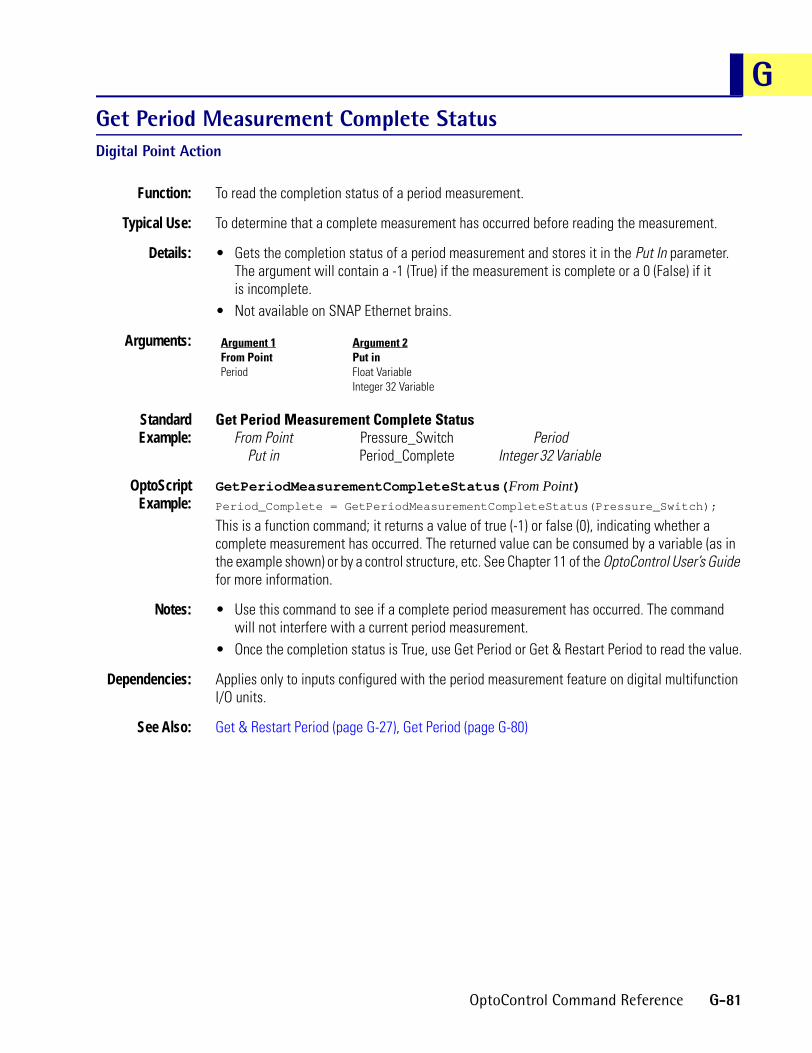
GGet Period Measurement Complete StatusDigital Point Action
Function: To read the completion status of a period measurement.
Typical Use: To determine that a complete measurement has occurred before reading the measurement.
Details: • Gets the completion status of a period measurement and stores it in the Put In parameter. The argument will contain a -1 (True) if the measurement is complete or a 0 (False) if itis incomplete.
• Not available on SNAP Ethernet brains.
Arguments:
StandardExample:
Get Period Measurement Complete StatusFrom Point Pressure_Switch Period
Put in Period_Complete Integer 32 Variable
OptoScriptExample:
GetPeriodMeasurementCompleteStatus(From Point)Period_Complete = GetPeriodMeasurementCompleteStatus(Pressure_Switch);
This is a function command; it returns a value of true (-1) or false (0), indicating whether a complete measurement has occurred. The returned value can be consumed by a variable (as in the example shown) or by a control structure, etc. See Chapter 11 of the OptoControl User’s Guide for more information.
Notes: • Use this command to see if a complete period measurement has occurred. The command will not interfere with a current period measurement.
• Once the completion status is True, use Get Period or Get & Restart Period to read the value.
Dependencies: Applies only to inputs configured with the period measurement feature on digital multifunction I/O units.
See Also: Get & Restart Period (page G-27), Get Period (page G-80)
Argument 1From PointPeriod
Argument 2Put inFloat VariableInteger 32 Variable
OptoControl Command Reference G-81

Get PID Control WordPID Action
Function: Reads the bits that represent the PID configuration.
Typical Use: To verify the PID configuration when troubleshooting.
Details: Bit assignments:11 1 = Use SqRt value from input channel. 0 = Use actual input value.10 1 = Setpoint was above high clamp. Write zero to clear.9 1 = Setpoint was below low clamp. Write zero to clear.8 1 = Input channel under-range. Write zero to clear.7 1 = Loop active. 0 = Loop reset (stopped).6 1 = Loop in auto mode. 0 = Loop in manual mode.5 1 = Output enabled. 0 = Output disabled (disconnected).4 1 = Output tracks input in manual mode. 0 = no action.3 1 = Setpoint tracks input in manual mode. 0 = no action.2 1 = Input from host. 0 = Input from channel.1 1 = Setpoint from channel. 0 = Setpoint from host.0 1 = Use filtered value from input channel. Must have filtering active on the input channel.
0 = Use current value of input channel.• This command is not for use with SNAP Ethernet I/O or the SNAP-PID-V module.
Arguments:
StandardExample:
Get PID Control WordFrom PID Loop Extruder_Zone08 PID Loop
Put in PID_CTRL_WORD Integer 32 Variable
OptoScriptExample:
GetPidControlWord(From PID Loop)PID_CTRL_WORD = GetPidControlWord(Extruder_Zone08);
This is a function command; it returns the bits that represent the PID configuration. The returned value can be consumed by a variable (as in the example shown) or by a control structure, etc. See Chapter 11 of the OptoControl User’s Guide for more information.
Notes: The PID Control Word is actually a 16-bit number. The four most significant bits are reserved.
See Also: Set PID Control Word (page S-29)
Argument 1From PID LoopPID Loop
Argument 2Put inInteger 32 Variable
G-82 OptoControl Command Reference

GGet PID D TermPID Action
Function: Reads the derivative value from the PID.
Typical Use: To store “as found” PID parameters for later use.
Details: • Reads the derivative value from the PID in the I/O unit. If the PID is disabled or the I/O unit is disabled, the last known value will be returned instead (the IVAL).
• This command is not for use with SNAP Ethernet I/O or the SNAP-PID-V module.
Arguments:
StandardExample:
Get PID D TermFrom PID Loop Extruder_Zone08 PID Loop
Put in Zone08_DTerm Float Variable
OptoScriptExample:
GetPidDTerm(From PID Loop)Zone08_DTerm = GetPidDTerm(Extruder_Zone08);
This is a function command; it returns the derivative value from the PID loop. The returned value can be consumed by a variable (as in the example shown) or by a mathematical expression, a control structure, etc. See Chapter 11 of the OptoControl User’s Guide for more information.
Notes: Always use a float variable to store the result.
See Also: Set PID D Term (page S-30)
Argument 1From PID LoopPID Loop
Argument 2Put inFloat VariableInteger 32 Variable
OptoControl Command Reference G-83

Get PID I TermPID Action
Function: Reads the Integral value from the PID.
Typical Use: To store “as found” PID parameters for later use.
Details: • Reads the Integral value from the PID in the I/O unit. If the PID is disabled or the I/O unit is disabled, the last known value will be returned instead (the IVAL).
• This command is not for use with SNAP Ethernet I/O or the SNAP-PID-V module.
Arguments:
StandardExample:
Get PID I TermFrom PID Loop Extruder_Zone08 PID Loop
Put in Zone08_ITerm Float Variable
OptoScriptExample:
GetPidITerm(From PID Loop)Zone08_ITerm = GetPidITerm(Extruder_Zone08);
This is a function command; it returns the integral value from the PID loop. The returned value can be consumed by a variable (as in the example shown) or by a mathematical expression, a control structure, etc. See Chapter 11 of the OptoControl User’s Guide for more information.
Notes: Always use a float variable to store the result.
See Also: Set PID I Term (page S-31)
Argument 1From PID LoopPID Loop
Argument 2Put inFloat VariableInteger 32 Variable
G-84 OptoControl Command Reference

GGet PID InputPID Action
Function: To read the input value (also known as the process variable) of the PID.
Typical Use: To verify that the input to the PID is within the working range.
Details: • The value read has the same engineering units as the specified PID input channel.• A value of -32,768 means the input is out of range and the PID output is no longer
being updated.• This command is not for use with SNAP Ethernet I/O or the SNAP-PID-V module.
Arguments:
StandardExample:
Get PID InputFrom PID Loop HEATER_3 PID Loop
Put in PID_INPUT_VALUE Float Variable
OptoScriptExample:
GetPidInput(From PID Loop)PID_INPUT_VALUE = GetPidInput(HEATER_3);
This is a function command; it returns the input value of the PID loop. The returned value can be consumed by a variable (as in the example shown) or by a mathematical expression, a control structure, etc. See Chapter 11 of the OptoControl User’s Guide for more information.
Notes: • See “PID Commands” in Chapter 10 of the OptoControl User’s Guide.• Use to detect bad or out-of-range PID input values. When such a value is found, use the
Move command to change the PID output as required.
Dependencies: • Communication to the PID must be enabled for this command to read the actual value from the PID.
• Requires an analog multifunction I/O unit (HRD I/O units are not supported).
See Also: Enable Communication to PID Loop (page E-7)
Argument 1From PID LoopPID Loop
Argument 2Put inFloat VariableInteger 32 Variable
OptoControl Command Reference G-85

Get PID ModePID Action
Function: Gets the auto/manual mode of the PID.
Typical Use: To store “as found” PID parameters for later use.
Details: • Reads auto/manual mode from the PID in the I/O unit. If the PID is disabled or the I/O unit is disabled, the last known value will be returned instead (the IVAL).
• Checks bit 6 of the PID control word. Returns a -1 (logical True) if in auto, otherwise a zero (logical False) is returned.
• This command is not for use with SNAP Ethernet I/O or the SNAP-PID-V module.
Arguments:
StandardExample:
Get PID ModeFrom PID Loop Extruder_Zone08 PID Loop
Put in ZONE08_MODE Integer 32 Variable
OptoScriptExample:
GetPidMode(From PID Loop)ZONE08_MODE = GetPidMode(Extruder_Zone08);
This is a function command; it returns a -1 if the PID loop is in auto mode or a zero if the PID loop is in manual mode. The returned value can be consumed by a variable (as in the example shown) or by a mathematical expression, a control structure, etc. See Chapter 11 of the OptoControl User’s Guide for more information.
See Also: Set PID Mode to Auto (page S-33), Set PID Mode to Manual (page S-34)
Argument 1From PID LoopPID Loop
Argument 2Put inFloat VariableInteger 32 Variable
G-86 OptoControl Command Reference

GGet PID OutputPID Action
Function: To read the output value of the PID.
Typical Use: To read the PID output and send it to a digital time proportional output (TPO) on a digital I/O unit.
Details: • The value read has the same engineering units as the specified PID output channel.• This command is not for use with SNAP Ethernet I/O or the SNAP-PID-V module.
Arguments:
StandardExample:
Get PID OutputFrom PID Loop HEATER_3 PID Loop
Put in PID_OUTPUT_VALUE Float Variable
OptoScriptExample:
GetPidOutput(From PID Loop)PID_OUTPUT_VALUE = GetPidOutput(HEATER_3);
This is a function command; it returns the output value of the PID loop. The returned value can be consumed by a variable (as in the example shown) or by a mathematical expression, a control structure, etc. See Chapter 11 of the OptoControl User’s Guide for more information.
Notes: • See “PID Commands” in Chapter 10 of the OptoControl User’s Guide.• Define the output channel as one of the upper eight channels (these channels do not have to
physically exist).• Scale this output channel 0–100, since the digital TPO wants to see a range of 0–100.• Use Set TPO Percent to send the value read from the PID output to the digital TPO. Do this
based on elapsed time. For example, if the TPO period is five seconds, send the value read at least every five seconds.
• This command can also be used to detect when the PID output is updated (which is always at the end of the scan period).
Dependencies: • Communication to the PID must be enabled for this command to read the actual value from the PID.
• Requires an analog multifunction I/O unit (HRD I/O units are not supported).
See Also: Enable Communication to PID Loop (page E-7), Set TPO Percent (page S-44), Set TPO Period (page S-45)
Argument 1From PID LoopPID Loop
Argument 2Put inFloat VariableInteger 32 Variable
OptoControl Command Reference G-87

Get PID Output Rate of ChangePID Action
Function: To read the output rate-of-change limit of the PID.
Typical Use: To verify that the output rate-of-change limit is as expected.
Details: • The output rate-of-change value defines how much the PID output can change per scan period. The units are the same as those defined for the PID output channel.
• The default value is the span of the output channel. This allows the PID output to move as much as 100 percent per scan period. For example, if the PID output channel is 4–20 mA, 16.00 would be returned by default, representing 100 percent of the span.
• This command is not for use with SNAP Ethernet I/O or the SNAP-PID-V module.
Arguments:
StandardExample:
Get PID Output Rate of ChangeFrom PID Loop HEATER_3 PID Loop
Put in PID_RATE_LIMIT Float Variable
OptoScriptExample:
GetPidOutputRateOfChange(From PID Loop)PID_RATE_LIMIT = GetPidOutputRateOfChange(HEATER_3);
This is a function command; it returns the output rate-of-change limit of the PID loop. The returned value can be consumed by a variable (as in the example shown) or by a mathematical expression, a control structure, etc. See Chapter 11 of the OptoControl User’s Guide for more information.
Notes: • See “PID Commands” in Chapter 10 of the OptoControl User’s Guide.• Many additional PID loop control features are available. See the Mistic Analog and Digital
Commands Manual (Opto 22 form 270) or consult Opto 22 Product Support.
Dependencies: • Communication to the PID must be enabled for this command to read the actual value from the PID.
• Requires an analog multifunction I/O unit (HRD I/O units are not supported).
See Also: Enable Communication to PID Loop (page E-7), Set PID Output Rate of Change (page S-35), Set PID Scan Rate (page S-37)
Argument 1From PID LoopPID Loop
Argument 2Put inFloat VariableInteger 32 Variable
G-88 OptoControl Command Reference

GGet PID P TermPID Action
Function: Reads the gain value from the PID.
Typical Use: To store “as found” PID parameters for later use.
Details: • Reads the gain value from the PID in the I/O unit. If the PID is disabled or the I/O unit is disabled, the last known value will be returned instead (the IVAL).
• This command is not for use with SNAP Ethernet I/O or the SNAP-PID-V module.
Arguments:
StandardExample:
Get PID P TermFrom PID Loop Extruder_Zone08 PID Loop
Put in Zone08_PTerm Float Variable
OptoScriptExample:
GetPidPTerm(From PID Loop)Zone08_PTerm = GetPidPTerm(Extruder_Zone08);
This is a function command; it returns the gain value from the PID. The returned value can be consumed by a variable (as in the example shown) or by a mathematical expression, a control structure, etc. See Chapter 11 of the OptoControl User’s Guide for more information.
Notes: Always use a float variable to store the result.
See Also: Set PID P Term (page S-36)
Argument 1From PID LoopPID Loop
Argument 2Put inFloat VariableInteger 32 Variable
OptoControl Command Reference G-89

Get PID Scan RatePID Action
Function: Gets the PID calculation interval.
Typical Use: To store “as found” PID parameters for later use.
Details: • Reads the Scan Rate value from the PID in the I/O unit. If the PID is disabled or the I/O unit is disabled, the last known value will be returned instead (the IVAL).
• This command is not for use with SNAP Ethernet I/O or the SNAP-PID-V module.
Arguments:
StandardExample:
Get PID Scan RateFrom PID Loop Extruder_Zone08 PID Loop
Put in Zone08_Scan_Rate Float Variable
OptoScriptExample:
GetPidScanRate(From PID Loop)Zone08_Scan_Rate = GetPidScanRate(Extruder_Zone08);
This is a function command; it returns the PID calculation interval (scan rate) for the PID loop. The returned value can be consumed by a variable (as in the example shown) or by a mathematical expression, a control structure, etc. See Chapter 11 of the OptoControl User’s Guide for more information.
Notes: Always use a float variable to store the result.
See Also: Set PID Scan Rate (page S-37)
Argument 1From PID LoopPID Loop
Argument 2Put inFloat VariableInteger 32 Variable
G-90 OptoControl Command Reference

GGet PID SetpointPID Action
Function: To read the setpoint value of the PID.
Typical Use: To verify that the setpoint of the PID is as expected and to store the setpoint for later use.
Details: • The value read has the same engineering units as the specified PID setpoint.• The setpoint can be an analog channel, or it can come from the program in the controller
using Set PID Setpoint.• This command is not for use with SNAP Ethernet I/O or the SNAP-PID-V module.
Arguments:
StandardExample:
Get PID SetpointFrom PID Loop Heater_3 PID Loop
Put in Pid_Setpoint_Value Float Variable
OptoScriptExample:
GetPidSetpoint(From PID Loop)PID_Setpoint_Value = GetPidSetpoint(Heater_3);
This is a function command; it returns the setpoint value of the PID loop. The returned value can be consumed by a variable (as in the example shown) or by a mathematical expression, a control structure, etc. See Chapter 11 of the OptoControl User’s Guide for more information.
Notes: • See “PID Commands” in Chapter 10 of the OptoControl User’s Guide.• Can be used to detect and log changes made to the PID setpoint.
Dependencies: • Communication to the PID must be enabled for this command to read the actual value from the PID.
• Requires an analog multifunction I/O unit (HRD I/O units are not supported).
See Also: Enable Communication to PID Loop (page E-7), Set PID Setpoint (page S-38)
Argument 1From PID LoopPID Loop
Argument 2Put inFloat VariableInteger 32 Variable
OptoControl Command Reference G-91

Get Port of I/O Unit Causing Current ErrorController Action
Function: To return the port number of the I/O unit that failed to respond if the top queue error is a 29.
Typical Use: Within an error handler in conjunction with Get Address of I/O Unit Causing Current Error, to log the date and time of a timeout error as well as the name and port number of the I/O unit that failed to respond. Use only when there are several I/O units with the same address on different ports.
Details: The controller generates a queue error 29 (timeout) whenever an I/O unit does not respond. This command can be used to determine the port number of the I/O unit that failed to respond.
Arguments:
StandardExample:
Get Port of I/O Unit Causing Current ErrorPut in IO_UNIT_PORT Integer 32 Variable
OptoScriptExample:
GetPortOfIoUnitCausingCurrentError()IO_UNIT_PORT = GetPortOfIoUnitCausingCurrentError();
This is a function command; it returns the port number of the I/O unit that caused the top error in the error queue. The returned value can be consumed by a variable (as in the example shown) or by a mathematical expression, a control structure, etc. See Chapter 11 of the OptoControl User’s Guide for more information.
Notes: • This command is typically used in an error handling chart.• In a system with many I/O units, this command can pinpoint exactly which I/O units are not
responding. The result can be put in an integer table or appended to an error message string for display on an HMI screen.
• Always use Error on I/O Unit? to determine if the top error in the error queue is an I/O unit error before using this command.
• Always use Remove Current Error and Point to Next Error after using this command.
Dependencies: For this command to have any effect, the top error in the queue must be a 29.
See Also: Get Address of I/O Unit Causing Current Error (page G-29), Error on I/O Unit? (page E-20), Remove Current Error and Point to Next Error (page R-26)
Argument 1Put inInteger 32 Variable
G-92 OptoControl Command Reference

GGet PriorityChart Action
Function: Returns the current priority of the chart using this command.
Typical Use: To determine the priority prior to changing it, so that it can be restored to its former value. Primarily used in a subroutine that increases its own priority while running and restores the priority of the chart that called it prior to ending.
Details: • The default priority of all charts is 1.• Since charts with different priorities can call the same subroutine, this command allows the
subroutine to save and restore the priority if the subroutine needs to change it.
Arguments:
StandardExample:
Get PriorityPut in PRIORITY Integer 32 Variable
OptoScriptExample:
GetPriority()PRIORITY = GetPriority();
This is a function command; it returns the priority of the chart in which the command exists. The returned value can be consumed by a variable (as in the example shown) or by a mathematical expression, a control structure, etc. See Chapter 11 of the OptoControl User’s Guide for more information.
See Also: Get Priority of Host Task (page G-94), Set Priority (page S-39)
Argument 1Put inFloat VariableInteger 32 Variable
OptoControl Command Reference G-93

Get Priority of Host TaskChart Action
Function: Returns the current priority of the specified host task.
Typical Use: To determine the priority of a host task prior to changing it so that it can be restored to its former value.
Details: The default priority of all tasks is 1.
Arguments:
StandardExample:
Get Priority of Host TaskOn Port 0 Integer 32 LiteralPut in PRIORITY Integer 32 Variable
OptoScriptExample:
GetPriorityOfHostTask(On Port)PRIORITY = GetPriorityOfHostTask(0);
This is a function command; it returns the priority of the host task. The returned value can be consumed by a variable (as in the example shown) or by a mathematical expression, a control structure, etc. See Chapter 11 of the OptoControl User’s Guide for more information.
See Also: Get Priority (page G-93), Set Priority of Host Task (page S-40)
Argument 1On PortInteger 32 LiteralInteger 32 Variable
Argument 2Put inInteger 32 Variable
G-94 OptoControl Command Reference

GGet Quadrature CounterDigital Point Action
Function: To read a quadrature counter value.
Typical Use: To read incremental encoders for positional or velocity measurement.
Details: • Reads the current value of a quadrature counter and places it in an argument specified by the Put In parameter.
• Does not reset the counter at the I/O unit to zero.• Does not stop the quadrature counter from continuing to count.• Valid range is -2,147,483,648 to 2,147,483,647 counts.• A positive value indicates forward movement (phase B leads phase A) and a negative value
indicates reverse movement (phase A leads phase B).• A quadrature counter occupies two adjacent channels. Input module pairs specifically made
for quadrature counting must be used. The first channel must be an even channel number on the digital multifunction I/O unit. For example, positions 0 and 1, 4 and 5 are valid, but 1 and 2, 3 and 4 are not.
Arguments:
StandardExample:
Get Quadrature CounterFrom Point ENCODER_1 Quadrature Counter
Put in TABLE_POSITION Integer 32 Variable
OptoScriptExample:
GetQuadratureCounter(From Point)TABLE_POSITION = GetQuadratureCounter(ENCODER_1);
This is a function command; it returns the value of the quadrature counter. The returned value can be consumed by a variable (as in the example shown) or by a mathematical expression, a control structure, etc. See Chapter 11 of the OptoControl User’s Guide for more information.
Notes: • The maximum encoder RPM will be related to the number of pulses per revolution that the encoder provides.
• The maximum input frequency is 12,500 Hz (pulses per second). Converting to minutes results in (12,500 pulses per second) * (60 seconds per minute) = 750,000 pulses per minute.
• Max Encoder RPM = (750,000 Pulses per Minute) / (Encoder Pulses [or lines] per Revolution)
Dependencies: • Always use Start Quadrature Counter once before using this command for the first time.• Applies only to input channels configured with the quadrature feature on digital
multifunction I/O units.
See Also: Get & Clear Quadrature Counter (page G-21), Start Quadrature Counter (page S-61), Stop Quadrature Counter (page S-67), Clear Quadrature Counter (page C-32)
Argument 1From PointQuadrature Counter
Argument 2Put inFloat VariableInteger 32 Variable
OptoControl Command Reference G-95

Get RTU/M4IO TemperatureController Action
Function: To obtain the temperature inside the M4RTU or M4IO controller case.
Typical Use: To determine if heating or cooling is required or has failed.
Details: • The temperature is reported in either Celsius or Fahrenheit depending on how I/O unit 1 on the local bus is configured.
• The temperature range is -40°C to 125°C (-40°F to 257°F).
Arguments:
StandardExample:
Get RTU/M4IO TemperaturePut in RTU_TEMP Float Variable
OptoScriptExample:
GetRtuM4IoTemperature()RTU_TEMP = GetRtuM4IoTemperature();
This is a function command; it returns the temperature inside the controller case. The returned value can be consumed by a variable (as in the example shown) or by a mathematical expression, a control structure, etc. See Chapter 11 of the OptoControl User’s Guide for more information.
Notes: • If I/O unit 1 is not configured, this command returns the temperature in degrees Celsius.• To read temperature in degrees Fahrenheit, make sure TEMP CNV is set to Degrees F when
configuring I/O unit 1. (To verify, select I/O Unit from the Configurator’s Configure menu, select the I/O unit, and click CHANGE.)
• Accuracy is:±0.5°C from 0°C to 70°C±1°C from -40°C to 0°C and from 70°C to 85°C±2°C from -55°C to -40°C and from 85°C to 125°C
Dependencies: An M4RTU or M4IO must be in use.
Result Data: If this command is used for a controller other than an M4RTU or M4IO, an error value of -32,768 is returned.
See Also: Get RTU/M4IO Voltage (page G-97)
Argument 1Put inFloat VariableInteger 32 Variable
G-96 OptoControl Command Reference

GGet RTU/M4IO VoltageController Action
Function: To read the input voltage furnished to the M4RTU or M4IO power supply.
Typical Use: To monitor battery voltage supplied to the M4RTU or M4IO power supply to determine if it’s getting low.
Details: • Reads voltage supplied to the input terminals by others.• Accuracy is plus or minus five percent.• Works with both AC and DC.
Arguments:
StandardExample:
Get RTU/M4IO VoltagePut in RTU_VOLTAGE Float Variable
OptoScriptExample:
GetRtuM4IoVoltage()RTU_VOLTAGE = GetRtuM4IoVoltage();
This is a function command; it returns the input voltage supplied to the the controller’s power supply. The returned value can be consumed by a variable (as in the example shown) or by a mathematical expression, a control structure, etc. See Chapter 11 of the OptoControl User’s Guide for more information.
Dependencies: An M4RTU or M4IO must be in use.
Result Data: If this command is used for a controller other than an M4RTU or M4IO, an error value of -32,768 is returned.
See Also: Get RTU/M4IO Temperature (page G-96)
Argument 1Put inFloat VariableInteger 32 Variable
OptoControl Command Reference G-97

Get SecondsTime/Date Action
Function: To read the second (0 through 59) from the controller’s real-time clock/calendar and put it into a numeric variable.
Typical Use: To use seconds information in an OptoControl program.
Details: • The destination variable can be an integer or a float, although an integer is preferred.• If the current time is 08:51:26, this action would place the value 26 into the Put In
parameter (Argument 1).
Arguments:
StandardExample:
Get SecondsPut In SECONDS Integer 32 Variable
OptoScriptExample:
GetSeconds()SECONDS = GetSeconds();
This is a function command; it returns the second (0 through 59) from the controller’s real-time clock. The returned value can be consumed by a variable (as in the example shown) or by a mathematical expression, a control structure, etc. See Chapter 11 of the OptoControl User’s Guide for more information.
Notes: • This is a one-time read of the second. If the second changes, you will need to execute this command again to get the value of the current second.
• Put this command in a small program loop that executes frequently to ensure that the variable always contains the current seconds value.
See Also: Get Day (page G-45), Get Hours (page G-59), Get Minutes (page G-64), Get Month (page G-66), Get Day of Week (page G-46), Get Year (page G-105), Set Day (page S-15), Set Day of Week (page S-16), Set Hours (page S-21), Set Minutes (page S-23), Set Month (page S-25), Set Seconds (page S-41) Set Year (page S-49)
Argument 1Put inFloat VariableInteger 32 Variable
G-98 OptoControl Command Reference

GGet Seconds Since MidnightTime/Date Action
Function: Gets the number of seconds since midnight.
Typical Use: In place of timers to determine time between events or to time stamp an event with a number rather than a string.
Details: Value returned is an integer from 0 to 86,400.
Arguments:
StandardExample:
Get Seconds Since MidnightPut in TIME_IN_SECONDS Integer 32 Variable
OptoScriptExample:
GetSecondsSinceMidnight()TIME_IN_SECONDS = GetSecondsSinceMidnight();
This is a function command; it returns the number of seconds since midnight. The returned value can be consumed by a variable (as in the example shown) or by a mathematical expression, a control structure, etc. See Chapter 11 of the OptoControl User’s Guide for more information.
Notes: To find elapsed time in HOURS, MINUTES, SECONDS since midnight using standard commands:
Move the seconds to an integer 32 variable: TEMP_VARDivide TEMP_VAR by: 3600 and move to: HOURSMODULO TEMP_VAR by: 3600 and move to: TEMP_VARDivide TEMP_VAR by: 60 and move to: MINUTESMODULO TEMP_VAR by: 60 and move to: SECONDS.
To find the same thing using OptoScript code:TEMP_VAR = GetSecondsSinceMidnight();
HOURS = TEMP_VAR / 3600;
MINUTES = (TEMP_VAR % 3600 / 60;SECONDS = (TEMP_VAR % 3600) % 60;
See Also: Get Seconds (page G-98)
Argument 1Put inFloat VariableInteger 32 Variable
OptoControl Command Reference G-99

Get Simple-64 I/O Unit as Binary ValueI/O Unit Action
Function: To read the current on/off status of all digital channels on the specified SNAP Simple I/O unit.
Typical Use: To efficiently read the status of all digital channels on a single I/O unit with one command.
Details: • Reads the current on/off status of all 64 digital channels on the SNAP Simple I/O unit specified.
• Updates the IVALs and XVALs for all 64 channels.• Reads outputs as well as inputs. Does not read analog channels at any position on the rack.• Returns status (a 64-bit integer) to the numeric variable specified.• If a channel is on, there will be a “1” in the respective bit. If the channel is off, there will be
a “0” in the respective bit. If the channel is analog, there will be a “0” in the respective bit. • If a specific channel is disabled, it will not be read. If the entire I/O unit is disabled, none of
the channels will be read.• The least significant bit corresponds to channel zero.
Arguments:
StandardExample:
Get Simple-64 I/O Unit as Binary ValueFrom INPUT_BOARD_2 SNAP Simple 64Put in IN_BD2_STATUS Integer 64 Variable
The effect of this command is illustrated below:
To save space, the example shows only the first eight and the last eight digital channels on the I/O unit. Channels with a value of 1 are on; channels with a value of 0 are off if digital, or they are analog channels.
OptoScriptExample:
GetSimple64IoUnitAsBinaryValue(I/O Unit)IN_BD2_STATUS = GetSimple64IoUnitAsBinaryValue(INPUT_BOARD_2);
This is a function command; it returns the on/off status of all digital points on the I/O unit, in the form of a bitmask. The returned value can be consumed by a variable (as shown) or by another item, such as a mathematical expression or a control structure. See Chapter 11 of the OptoControl User’s Guide for more information.
Notes: Use Bit Test to examine individual bits.
See Also: Set Simple-64 I/O Unit from MOMO Masks (page S-42)
Argument 1FromSNAP Simple 64
Argument 2Put inInteger 64 Variable
Point Number 63 62 61 60 59 58 57 56 7 6 5 4 3 2 1 0
Bit mask
Binary 0 1 1 0 1 1 0 0 0 1 0 0 0 0 1 0
Hex 6 C 4 2
G-100 OptoControl Command Reference

GGet Simple-64 I/O Unit LatchesI/O Unit Action
Function: To read all on and off latches (as well as the state of all points) on a SNAP Simple I/O unit.
Typical Use: To read all point states and all latches in a bank, instead of individually.
Details: • Reads the states of all points and the states of all on-latches and off-latches at once.• Off-latches detect on-off-on input transitions; on-latches detect off-on-off transitions. These
quick transitions occur too fast for the controller to detect otherwise, since they are processed by the I/O unit.
Arguments:
Arguments 2, 3, and 4 are returned as 64-bit masks. If the point or latch is on, a 1 appears in the respective bit. If the point or latch is off, a 0 appears. For example:
To save space, this example shows only the first eight points and the last eight points. You can see that the points (or latches) 1, 6, 58, 59, 61, and 62 are on.
StandardExample:
Get Simple-64 I/O Unit LatchesFrom I/O_Unit_A SNAP Simple 64State Unit_A_State Integer 64 Variable
On-Latch Unit_A_On_Latches Integer 64 VariableOff-Latch Unit_A_Off_Latches Integer 64 Variable
OptoScriptExample:
GetSimple64IoUnitLatches(From, State, On-Latch, Off-Latch)GetSimple64IoUnitLatches(I/O_Unit_A, Unit_A_State, Unit_A_On_Latches,
Unit_A_Off_Latches);
This is a procedure command; it does not return a value. See Chapter 11 of the OptoControl User’s Guide for more information.
Notes: The ability of the I/O unit to detect fast input transitions is limited by the input module’s turn-on and turn-off times. Check the specifications for the module to be used.
See Also: Get & Clear Simple-64 I/O Unit Latches (page G-22), Get Off-Latch (page G-72), Clear Off-Latch (page C-28), Clear All Latches (page C-24)
Argument 1FromSNAP Simple 64
Argument 2StateInteger 64 Variable
Argument 3On-LatchInteger 64 Variable
Argument 4Off-LatchInteger 64 Variable
Point Number 63 62 61 60 59 58 57 56 7 6 5 4 3 2 1 0
Bit mask
Binary 0 1 1 0 1 1 0 0 0 1 0 0 0 0 1 0
Hex 6 C 4 2
OptoControl Command Reference G-101
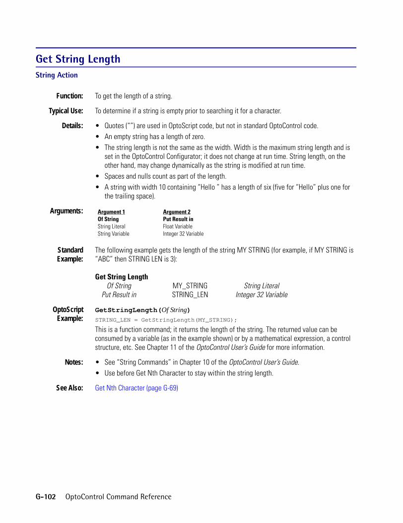
Get String LengthString Action
Function: To get the length of a string.
Typical Use: To determine if a string is empty prior to searching it for a character.
Details: • Quotes (“”) are used in OptoScript code, but not in standard OptoControl code.• An empty string has a length of zero.• The string length is not the same as the width. Width is the maximum string length and is
set in the OptoControl Configurator; it does not change at run time. String length, on the other hand, may change dynamically as the string is modified at run time.
• Spaces and nulls count as part of the length.• A string with width 10 containing “Hello ” has a length of six (five for “Hello” plus one for
the trailing space).
Arguments:
StandardExample:
The following example gets the length of the string MY STRING (for example, if MY STRING is “ABC” then STRING LEN is 3):
Get String LengthOf String MY_STRING String Literal
Put Result in STRING_LEN Integer 32 Variable
OptoScriptExample:
GetStringLength(Of String)STRING_LEN = GetStringLength(MY_STRING);
This is a function command; it returns the length of the string. The returned value can be consumed by a variable (as in the example shown) or by a mathematical expression, a control structure, etc. See Chapter 11 of the OptoControl User’s Guide for more information.
Notes: • See “String Commands” in Chapter 10 of the OptoControl User’s Guide.• Use before Get Nth Character to stay within the string length.
See Also: Get Nth Character (page G-69)
Argument 1Of StringString LiteralString Variable
Argument 2Put Result inFloat VariableInteger 32 Variable
G-102 OptoControl Command Reference

GGet SubstringString Action
Function: To copy a portion of a string.
Typical Uses: To parse or extract data from a string, to skip leading or trailing characters, or to extract data from strings that may contain starting and ending character sequences generated by barcode readers or scales.
Details: • Quotes (“”) are used in OptoScript code, but not in standard OptoControl code.• Valid range for Start At Index (Argument 2) is 1 to the string length. If it is less than 1, 1 will
be assumed.• If the combination of the Start At Index (Argument 2) and Num. Characters (Argument 3)
extend beyond the length of the source string, only the available portion of the source string will be returned.
• The following are examples of this command applied to the string “MONTUEWEDTHRFRI”:Start At Number of Characters Substring Returned
1 3 “MON”4 3 “TUE”1 4 “MONT”
14 3 “RI”16 5 “”
Arguments:
StandardExample:
The following example gets a single day from the string “MONTUEWEDTHRFRI”; quotes are shown here for clarity only. Do not use them in standard commands.
Get SubstringFrom String “MONTUEWEDTHRFRI” String Literal
Start at Index INDEX Integer 32 VariableNum. Characters 3 Integer 32 Literal
Put Result in STRING String Variable
OptoScriptExample:
GetSubstring(From String, Start at Index, Num. Characters, Put Result in)GetSubstring("MONTUEWEDTHRFRI", INDEX, 3, STRING);
This is a procedure command; it does not return a value. Quotes are required in OptoScript code.
Notes: • See “String Commands” in Chapter 10 of the OptoControl User’s Guide.• You can get text that follows a delimiter (such as a space) within a string. Create a loop that
first uses Get Nth Character to extract a character, then compares it to the delimiter (character 32 in the case of a space). If the character is equal to the delimiter, add 1 to the N argument and use the new N as the Start At parameter above.
• See Move from String Table for a similar example.
See Also: Get Nth Character (page G-69)
Argument 1From StringString LiteralString Variable
Argument 2Start at IndexInteger 32 LiteralInteger 32 Variable
Argument 3Num. CharactersInteger 32 LiteralInteger 32 Variable
Argument 4Put Result inString Variable
OptoControl Command Reference G-103

Get System TimeTime/Date Action
Function: Gets the number of seconds since the controller has been turned on.
Typical Use: Accumulate “up-time.”
Details: Value returned is an integer from zero to two billion.
Arguments:
StandardExample:
Get System TimePut in TIME_IN_SECONDS Integer 32 Variable
OptoScriptExample:
GetSystemTime()TIME_IN_SECONDS = GetSystemTime();
This is a function command; it returns the number of seconds since the controller was last turned on. The returned value can be consumed by a variable (as in the example shown) or by a mathematical expression, a control structure, etc. See Chapter 11 of the OptoControl User’s Guide for more information.
See Also: Get Seconds Since Midnight (page G-99)
Argument 1Put inFloat VariableInteger 32 Variable
G-104 OptoControl Command Reference

GGet YearTime/Date Action
Function: To read the year value (00 through 99) from the controller’s real-time clock/calendar and put it into a numeric variable.
Typical Use: To use year information in an OptoControl program.
Details: • The destination variable can be an integer or a float, although an integer is preferred.• If the current date is March 2, 2000, this action would place the value 00 into the Put In
parameter (Argument 1).
Arguments:
StandardExample:
Get YearPut In YEAR Integer 32 Variable
OptoScriptExample:
GetYear()YEAR = GetYear();
This is a function command; it returns the last two digits of the year (00 through 99). The returned value can be consumed by a variable (as in the example shown) or by a mathematical expression, a control structure, etc. See Chapter 11 of the OptoControl User’s Guide for more information.
Notes: • This is a one-time read of the year. If the year changes, you will need to execute this command again to get the value of the current year.
• Put this command in a small program loop that executes frequently to ensure that the variable always contains the current year value.
See Also: Get Day (page G-45), Get Hours (page G-59), Get Minutes (page G-64), Get Month (page G-66), Get Seconds (page G-98), Get Day of Week (page G-46), Set Day (page S-15), Set Day of Week (page S-16), Set Hours (page S-21), Set Minutes (page S-23), Set Month (page S-25), Set Seconds (page S-41) Set Year (page S-49)
Argument 1Put inFloat VariableInteger 32 Variable
OptoControl Command Reference G-105

Greater?Logical Condition
Function: To determine if one numeric value is greater than another.
Typical Use: To determine if a counter has reached an upper limit.
Details: • Determines if Argument 1 is greater than Argument 2. Examples:Argument 1 Argument 2 Result
0 0 False-1 0 False-1 -3 True
22.221 22.220 True
• Evaluates True if Argument 1 is greater than Argument 2, False otherwise.
Arguments:
StandardExample:
Is CALCULATED_VALUE Integer 32 VariableGreater?
Than 1000 Integer 32 Literal
OptoScriptExample:
OptoScript doesn’t use a command; the function is built in. Use the > operator.if (CALCULATED_VALUE > 1000) then
Notes: • See “Logical Commands” in Chapter 10 of the OptoControl User’s Guide. For more on comparison operators in OptoScript code, see Chapter 11 of the OptoControl User’s Guide.
• Use Within Limits? to test for an approximate match. To test for less than or equal, use either Less Than or Equal? or the false exit.
See Also: Less? (page L-1), Not Equal? (page N-4), Greater Than or Equal? (page G-107), Less Than or Equal? (page L-2), Within Limits? (page W-1)
Argument 1IsAnalog InputAnalog OutputCounterDigital InputDigital OutputDown Timer VariableFloat LiteralFloat VariableFrequencyInteger 32 LiteralInteger 32 VariableInteger 64 LiteralInteger 64 VariableLocal Simple Digital InputLocal Simple Digital OutputOff PulseOff TotalizerOn PulseOn TotalizerPeriodQuadrature CounterUp Timer Variable
Argument 2ThanAnalog InputAnalog OutputCounterDigital InputDigital OutputDown Timer VariableFloat LiteralFloat VariableFrequencyInteger 32 LiteralInteger 32 VariableInteger 64 LiteralInteger 64 VariableLocal Simple Digital InputLocal Simple Digital OutputOff PulseOff TotalizerOn PulseOn TotalizerPeriodQuadrature CounterUp Timer Variable
G-106 OptoControl Command Reference

GGreater Than or Equal?Logical Condition
Function: To determine if one numeric value is greater than or equal to another.
Typical Use: To determine if a value has reached an upper limit.
Details: • Determines if Argument 1 is greater than or equal to Argument 2. Examples:Argument 1 Argument 2 Result
0 0 True1 0 True
-32768 -32767 False22221 2222 True
• Evaluates True if the first value is greater than or equal to the second, False otherwise.
Arguments:
StandardExample:
Is ROOM_TEMP Analog InputGreater Than or Equal?
To 78.5000 Float Literal
OptoScriptExample:
OptoScript doesn’t use a command; the function is built in. Use the >= operator.if (ROOM_TEMP >= 78.5000) then
Notes: • See “Logical Commands” in Chapter 10 of the OptoControl User’s Guide. For more on comparison operators in OptoScript code, see Chapter 11 of the OptoControl User’s Guide.
• Use Within Limits? to test for an approximate match. To test for less than, use either Less? or the False exit.
Argument 1IsAnalog InputAnalog OutputCounterDigital InputDigital OutputDown Timer VariableFloat LiteralFloat VariableFrequencyInteger 32 LiteralInteger 32 VariableInteger 64 LiteralInteger 64 VariableLocal Simple Digital InputLocal Simple Digital OutputOff PulseOff TotalizerOn PulseOn TotalizerPeriodQuadrature CounterUp Timer Variable
Argument 2ToAnalog InputAnalog OutputCounterDigital InputDigital OutputDown Timer VariableFloat LiteralFloat VariableFrequencyInteger 32 LiteralInteger 32 VariableInteger 64 LiteralInteger 64 VariableLocal Simple Digital InputLocal Simple Digital OutputOff PulseOff TotalizerOn PulseOn TotalizerPeriodQuadrature CounterUp Timer Variable
OptoControl Command Reference G-107

• When using analog values or digital features in this command, be sure to take into consideration the units that the value is read in and adjust the test values accordingly.
See Also: Less? (page L-1), Not Equal? (page N-4), Less Than or Equal? (page L-2), Within Limits? (page W-1)
Greater Than or Equal to Table Element?Logical Condition
Function: To determine if a numeric value is greater than or equal to a specified value in a float or integer table.
Typical Use: To store peak values.
Details: • Determines if one value (Argument 1) is greater than or equal to another (a value at index Argument 2 in float or integer table Argument 3). Examples:
Value 1 Value 2 Result0.0 0.0 True
0.0001 0.0 True22.22 22.222 False
-32768 -32767 False22221 2222 True
• Evaluates True if the first value is greater than or equal to the second, False otherwise.
Arguments: Argument 1IsAnalog InputAnalog OutputCounterDigital InputDigital OutputDown Timer VariableFloat LiteralFloat VariableFrequencyInteger 32 LiteralInteger 32 VariableInteger 64 LiteralInteger 64 VariableLocal Simple Digital InputLocal Simple Digital OutputOff PulseOff TotalizerOn PulseOn TotalizerPeriodQuadrature CounterUp Timer Variable
Argument 2At IndexInteger 32 LiteralInteger 32 Variable
Argument 3Of TableFloat TableInteger 32 TableInteger 64 Table
G-108 OptoControl Command Reference

GStandardExample:
Is THIS_READING Float VariableGreater Than or Equal to Table Element?
At Index TABLE_INDEX Integer 32 VariableOf Table TABLE_OF_READINGS Float Table
OptoScriptExample:
OptoScript doesn’t use a command; the function is built in. Use the >= operator.if (THIS_READING >= TABLE_OF_READINGS[TABLE_INDEX]) then
Notes: • See “Logical Commands” in Chapter 10 of the OptoControl User’s Guide. For more on comparison operators in OptoScript code, see Chapter 11 of the OptoControl User’s Guide.
• To test for less than, use either Less Than Table Element? or the False exit.
Queue Errors: 32 = Bad table index value—index was negative or greater than or equal to table size.
See Also: Less Than Table Element? (page L-5), Not Equal to Table Element? (page N-5), Less Than or Equal to Table Element? (page L-3)
Greater Than Table Element?Logical Condition
Function: To determine if a numeric value is greater than a specified value in a float or integer table.
Typical Use: To store peak values.
Details: • Determines if one value (Argument 1) is greater than another (a value at index Argument 2 in float or integer table Argument 3). Examples:
Value 1 Value 2 Result0.0 0.0 False
0.0001 0.0 True-98.765 -98.765 False
1 0 True22221 2222 True
• Evaluates True if the first value is greater than the second, False otherwise.
OptoControl Command Reference G-109

Arguments:
StandardExample:
Is THIS_READING Float VariableGreater Than Table Element?
At Index TABLE_INDEX Integer 32 VariableOf Table TABLE_OF_READINGS Float Table
OptoScriptExample:
OptoScript doesn’t use a command; the function is built in. Use the > operator.if (THIS_READING > TABLE_OF_READINGS[TABLE_INDEX]) then
Notes: • See “Logical Commands” in Chapter 10 of the OptoControl User’s Guide. For more on comparison operators in OptoScript code, see Chapter 11 of the OptoControl User’s Guide.
• To test for less than or equal to, use either Less Than or Equal to Table Element? or the False exit.
Queue Errors: 32 = Bad table index value—index was negative or greater than the table size.
See Also: Less Than Table Element? (page L-5), Not Equal to Table Element? (page N-5), Greater Than or Equal to Table Element? (page G-108), Less Than or Equal to Table Element? (page L-3)
Argument 1IsAnalog InputAnalog OutputCounterDigital InputDigital OutputDown Timer VariableFloat LiteralFloat VariableFrequencyInteger 32 LiteralInteger 32 VariableInteger 64 LiteralInteger 64 VariableLocal Simple Digital InputLocal Simple Digital OutputOff PulseOff TotalizerOn PulseOn TotalizerPeriodQuadrature CounterUp Timer Variable
Argument 2At IndexInteger 32 LiteralInteger 32 Variable
Argument 3Of TableFloat TableInteger 32 TableInteger 64 Table
G-110 OptoControl Command Reference

H
HHost Task Received a Message?Chart ConditionFunction: To determine if a message has been received on the specified host port.
Typical Use: To determine if OptoDisplay has stopped communicating with the controller.
Details: Evaluates True if a message has been received on the specified host port since the last use of this command, False otherwise.
Arguments:
StandardExample:
On Port 4 Integer 32 LiteralHost Task Received a Message?
OptoScriptExample:
HasHostTaskReceivedMessage(On Port)if (HasHostTaskReceivedMessage(4)) then
This is a function command; it returns a value of true (non-zero) or false (0). The returned value can be consumed by a control structure (as in the example shown) or by a variable, I/O point, etc. See Chapter 11 of the OptoControl User’s Guide for more information.
Notes: See “Chart Commands” in Chapter 10 of the OptoControl User’s Guide.
Queue Errors: 30 = Incorrect port number—use zero to four or eight.
See Also: ARCNET Node Present? (page A-12) ARCNET Message Address Equal to? (page A-11)
Argument 1On PortInteger 32 LiteralInteger 32 Variable
OptoControl Command Reference H-1

Hyperbolic CosineMathematical Action
Function: To derive the hyperbolic cosine of a value.
Typical Use: To solve hyperbolic calculations.
Details: • Calculates the hyperbolic cosine of Argument 1 and places the result in Argument 2.• Argument 1 (the operand) must be a value from -88.33654 to 88.72283.
Arguments:
StandardExample:
Hyperbolic CosineOf 2.0 Float Literal
Put Result in ANSWER Float Variable
OptoScriptExample:
HyperbolicCosine(Of)ANSWER = HyperbolicCosine(2.0);
This is a function command; it returns the hyperbolic cosine of the value. The returned value can be consumed by a variable (as in the example shown) or by a control structure, mathematical expression, etc. See Chapter 11 of the OptoControl User’s Guide for more information.
Queue Errors: 33 = Overflow error—result too large.
See Also: Hyperbolic Sine (page H-3), Hyperbolic Tangent (page H-4)
Argument 1OfAnalog InputAnalog OutputDown Timer VariableFloat LiteralFloat VariableInteger 32 LiteralInteger 32 VariableUp Timer Variable
Argument 2Put Result inAnalog OutputDown Timer VariableFloat VariableInteger 32 VariableUp Timer Variable
H-2 OptoControl Command Reference

HHyperbolic SineMathematical Action
Function: To derive the hyperbolic sine of a value.
Typical Use: To solve hyperbolic calculations.
Details: • Calculates the hyperbolic sine of Argument 1 and places the result in Argument 2.• Argument 1 (the operand) must be a value from -88.33654 to 88.72283.
Arguments:
StandardExample:
Hyperbolic SineOf 2.0 Float Literal
Put Result in ANSWER Float Variable
OptoScriptExample:
HyperbolicSine(Of)ANSWER = HyperbolicSine(2.0);
This is a function command; it returns the hyperblic sine of the value. The returned value can be consumed by a variable (as in the example shown) or by a control structure, mathematical expression, etc. See Chapter 11 of the OptoControl User’s Guide for more information.
Queue Errors: 33 = Overflow error—result too large.
See Also: Hyperbolic Cosine (page H-2), Hyperbolic Tangent (page H-4)
Argument 1OfAnalog InputAnalog OutputDown Timer VariableFloat LiteralFloat VariableInteger 32 LiteralInteger 32 VariableUp Timer Variable
Argument 2Put Result inAnalog OutputDown Timer VariableFloat VariableInteger 32 VariableUp Timer Variable
OptoControl Command Reference H-3

Hyperbolic TangentMathematical Action
Function: To derive the hyperbolic tangent of a value.
Typical Use: To solve hyperbolic calculations.
Details: • Calculates the hyperbolic tangent of Argument 1 and places the result in Argument 2.• Argument 1 (the operand) must be a value between -8.21 and 8.665.• The result is a value ranging from -1.0 to 1.0.
Arguments:
StandardExample:
Hyperbolic TangentOf 2.0 Float Literal
Put Result in ANSWER Float Variable
OptoScriptExample:
HyperbolicTangent(Of)ANSWER = HyperbolicTangent(2.0);
This is a function command; it returns the hyperbolic tangent of the value. The returned value can be consumed by a variable (as in the example shown) or by a control structure, mathematical expression, etc. See Chapter 11 of the OptoControl User’s Guide for more information.
Queue Errors: 33 = Overflow error—result too large.35 = Not a number—result invalid.
See Also: Hyperbolic Cosine (page H-2), Hyperbolic Sine (page H-3)
Argument 1OfAnalog InputAnalog OutputDown Timer VariableFloat LiteralFloat VariableInteger 32 LiteralInteger 32 VariableUp Timer Variable
Argument 2Put Result inAnalog OutputDown Timer VariableFloat VariableInteger 32 VariableUp Timer Variable
H-4 OptoControl Command Reference

I
IIncrement VariableMathematical ActionFunction: To increase the value specified by 1.
Typical Use: To control loop counters and other counting applications.
Details: Same as adding 1: 8 becomes 9, -1 becomes 0, 12.33 becomes 13.33, etc.
Arguments:
StandardExample:
Increment VariableLOOP_COUNTER Integer 32 Variable
OptoScriptExample:
IncrementVariable(Variable)IncrementVariable(LOOP_COUNTER);
This is a procedure command; it does not return a value.
Notes: • See “Mathematical Commands” in Chapter 10 of the OptoControl User’s Guide.• Executes faster than adding 1.
See Also: Decrement Variable (page D-1),
Argument 1[Value]Float VariableInteger 32 VariableInteger 64 Variable
OptoControl Command Reference I-1

Interrupt Disabled for Event?Event/Reaction Condition
Function: To determine if the interrupt for a specific event/reaction is inactive.
Typical Use: To verify the active/inactive state of the interrupt for a specific event/reaction.
Details: • Evaluates True if the interrupt for the specified event/reaction is not active, False if it is active.
• Event/reactions still occur when the interrupt is disabled as long as they are active.
Arguments:
StandardExample:
Event/Reaction Sequence_FinishedInterrupt Disabled for Event?
OptoScriptExample:
IsInterruptDisabledForEvent(Event/Reaction)if (IsInterruptDisabledForEvent(Sequence_Finished)) then
This is a function command; it returns a value of true (non-zero) or false (0). The returned value can be consumed by a control structure (as in the example shown) or by a variable, I/O point, etc. See Chapter 11 of the OptoControl User’s Guide for more information.
Notes: See “Event/Reaction Commands” in Chapter 10 of the OptoControl User’s Guide.
Dependencies: • Event/reactions must be named and configured on the I/O unit before they can be referenced.
• Event/reactions are not supported on local simple I/O units.
See Also: Enable Interrupt on Event (page E-10), Interrupt Enabled for Event? (page I-3)
Argument 1Event/ReactionAnalog Event/ReactionDigital Event/Reaction
I-2 OptoControl Command Reference

IInterrupt Enabled for Event?Event/Reaction Condition
Function: To determine if the interrupt for a specific event/reaction is active.
Typical Use: To verify the active/inactive state of the interrupt for a specific event/reaction.
Details: • Evaluates True if the interrupt for the specified event/reaction is active, False if it is not active.
• Event/reactions still occur when the interrupt is disabled as long as they are active.
Arguments:
StandardExample:
Event/Reaction Sequence_FinishedInterrupt Enabled for Event?
OptoScriptExample:
IsInterruptEnabledForEvent(Event/Reaction)if (IsInterruptEnabledForEvent(Sequence_Finished)) then
This is a function command; it returns a value of true (non-zero) or false (0). The returned value can be consumed by a control structure (as in the example shown) or by a variable, I/O point, etc. See Chapter 11 of the OptoControl User’s Guide for more information.
Notes: See “Event/Reaction Commands” in Chapter 10 of the OptoControl User’s Guide.
Dependencies: • Event/reactions must be named and configured on the I/O unit before they can be referenced.
• Event/reactions are not supported on local simple I/O units.
See Also: Enable Interrupt on Event (page E-10), Interrupt Disabled for Event? (page I-2)
Argument 1Event/ReactionAnalog Event/ReactionDigital Event/Reaction
OptoControl Command Reference I-3

Interrupt on Port0?Communication—Serial Condition
Function: To determine if the I/O unit that generated the interrupt is connected to COM Port 0 of the controller.
Typical Use: To reduce the number of I/O units that must be polled to determine which I/O unit may have triggered the interrupt.
Details: Evaluates True if the I/O unit that generated the interrupt is on COM Port 0, False otherwise.
Arguments: None.
StandardExample:
Interrupt on Port0?
OptoScriptExample:
IsInterruptOnPort0()if (IsInterruptOnPort0()) then
This is a function command; it returns a value of true (non-zero) or false (0). The returned value can be consumed by a control structure (as in the example shown) or by a variable, I/O point, etc. See Chapter 11 of the OptoControl User’s Guide for more information.
Notes: • Use Generating Interrupt? to determine which I/O unit on COM Port 0 generated the interrupt.
• See “Event/Reaction Commands” in Chapter 10 of the OptoControl User’s Guide.
See Also: Interrupt on Port1? (page I-4), Interrupt on Port2? (page I-5), Interrupt on Port3? (page I-6), Interrupt on Port6? (page I-6), Generating Interrupt? (page G-9), Get Active Interrupt Mask (page G-28)
Interrupt on Port1?Communication—Serial Condition
Function: To determine if the I/O unit that generated the interrupt is connected to COM Port 1 of the controller.
Typical Use: To reduce the number of I/O units that must be polled to determine which I/O unit may have triggered the interrupt.
Details: Evaluates True if the I/O unit that generated the interrupt is on COM Port 1, False otherwise.
Arguments: None.
StandardExample:
Interrupt on Port1?
I-4 OptoControl Command Reference

IOptoScript
Example:IsInterruptOnPort1()if (IsInterruptOnPort1()) then
This is a function command; it returns a value of true (non-zero) or false (0). The returned value can be consumed by a control structure (as in the example shown) or by a variable, I/O point, etc. See Chapter 11 of the OptoControl User’s Guide for more information.
Notes: • Use Generating Interrupt? to determine which I/O unit on COM Port 1 generated the interrupt.
• See “Event/Reaction Commands” in Chapter 10 of the OptoControl User’s Guide.
See Also: Interrupt on Port0? (page I-4), Interrupt on Port2? (page I-5), Interrupt on Port3? (page I-6), Interrupt on Port6? (page I-6), Generating Interrupt? (page G-9), Get Active Interrupt Mask (page G-28)
Interrupt on Port2?Communication—Serial Condition
Function: To determine if the I/O unit that generated the interrupt is connected to COM Port 2 of the controller.
Typical Use: To reduce the number of I/O units that must be polled to determine which I/O unit may have triggered the interrupt.
Details: Evaluates True if the I/O unit that generated the interrupt is on COM Port 2, False otherwise.
Arguments: None.
StandardExample:
Interrupt on Port2?
OptoScriptExample:
IsInterruptOnPort2()if (IsInterruptOnPort2()) then
This is a function command; it returns a value of true (non-zero) or false (0). The returned value can be consumed by a control structure (as in the example shown) or by a variable, I/O point, etc. See Chapter 11 of the OptoControl User’s Guide for more information.
Notes: • Use Generating Interrupt? to determine which I/O unit on COM Port 2 generated the interrupt.
• See “Event/Reaction Commands” in Chapter 10 of the OptoControl User’s Guide.
See Also: Interrupt on Port1? (page I-4), Interrupt on Port0? (page I-4), Interrupt on Port3? (page I-6), Interrupt on Port6? (page I-6), Generating Interrupt? (page G-9), Get Active Interrupt Mask (page G-28)
OptoControl Command Reference I-5

Interrupt on Port3?Communication—Serial Condition
Function: To determine if the I/O unit that generated the interrupt is connected to COM Port 3 of the controller.
Typical Use: To reduce the number of I/O units that must be polled to determine which I/O unit may have triggered the interrupt.
Details: Evaluates True if the I/O unit that generated the interrupt is on COM Port 3, False otherwise.
Arguments: None.
StandardExample:
Interrupt on Port3?
OptoScriptExample:
IsInterruptOnPort3()if (IsInterruptOnPort3()) then
This is a function command; it returns a value of true (non-zero) or false (0). The returned value can be consumed by a control structure (as in the example shown) or by a variable, I/O point, etc. See Chapter 11 of the OptoControl User’s Guide for more information.
Notes: • Use Generating Interrupt? to determine which I/O unit on COM Port 3 generatedthe interrupt.
• See “Event/Reaction Commands” in Chapter 10 of the OptoControl User’s Guide.
See Also: Interrupt on Port1? (page I-4), Interrupt on Port2? (page I-5), Interrupt on Port0? (page I-4), Interrupt on Port6? (page I-6), Generating Interrupt? (page G-9), Get Active Interrupt Mask (page G-28)
Interrupt on Port6?Communication—Serial Condition
Function: To determine if the I/O unit that generated the interrupt is connected to COM Port 6 of the controller.
Typical Use: To reduce the number of I/O units that must be polled to determine which I/O unit may have triggered the interrupt.
Details: Evaluates True if the I/O unit that generated the interrupt is on COM Port 6, False otherwise.
Arguments: None.
StandardExample:
Interrupt on Port6?
I-6 OptoControl Command Reference

IOptoScript
Example:IsInterruptOnPort6()if (IsInterruptOnPort6()) then
This is a function command; it returns a value of true (non-zero) or false (0). The returned value can be consumed by a control structure (as in the example shown) or by a variable, I/O point, etc. See Chapter 11 of the OptoControl User’s Guide for more information.
Notes: • Use Generating Interrupt? to determine which I/O unit on COM Port 6 generatedthe interrupt.
• See “Event/Reaction Commands” in Chapter 10 of the OptoControl User’s Guide.
See Also: Interrupt on Port1? (page I-4), Interrupt on Port2? (page I-5), Interrupt on Port3? (page I-6), Interrupt on Port0? (page I-4), Generating Interrupt? (page G-9), Get Active Interrupt Mask (page G-28)
I/O Point Communication Enabled?Simulation Condition
Function: Checks a flag internal to the controller to determine if communication to the specified I/O point is enabled.
Typical Use: Primarily used in factory QA testing and simulation.
Details: Evaluates True if communication is enabled.
Arguments:
StandardExample:
I/O Point PUMP_3_STATUS Analog InputI/O Point Communication Enabled?
OptoScriptExample:
IsIoPointCommEnabled(I/O Point)if (IsIoPointCommEnabled(PUMP_3_STATUS)) then
This is a function command; it returns a value of true (non-zero) or false (0). The returned value can be consumed by a control structure (as in the example shown) or by a variable, I/O point, etc. See Chapter 11 of the OptoControl User’s Guide for more information.
See Also: I/O Unit Communication Enabled? (page I-8)
Argument 1I/O PointAnalog InputAnalog OutputDigital InputDigital OutputLocal Simple Digital InputLocal Simple Digital Output
OptoControl Command Reference I-7

I/O Unit Communication Enabled?Simulation Condition
Function: Checks a flag internal to the controller to determine if communication to the specified I/O unit is enabled.
Typical Use: Primarily used in factory QA testing and simulation.
Details: Evaluates True if communication is enabled.
Arguments:
StandardExample:
I/O Unit PUMP_HOUSE B3000 SNAP DigitalI/O Unit Communication Enabled?
OptoScriptExample:
IsIoUnitCommEnabled(I/O Unit)if (IsIoUnitCommEnabled(PUMP_HOUSE)) then
This is a function command; it returns a value of true (non-zero) or false (0). The returned value can be consumed by a control structure (as in the example shown) or by a variable, I/O point, etc. See Chapter 11 of the OptoControl User’s Guide for more information.
See Also: I/O Point Communication Enabled? (page I-7), I/O Unit Ready? (page I-9)
Argument 1I/O UnitB100 Digital Multifunction I/O UnitB200 Analog Multifunction I/O UnitB3000 SNAP AnalogB3000 SNAP DigitalB3000 SNAP Mixed I/OG4 Analog Multifunction I/O UnitG4 Digital Local Simple I/O UnitG4 Digital Multifunction I/O UnitG4 Digital Remote Simple I/O UnitHRD Analog Current Output I/O UnitHRD Analog RTD Input I/O UnitHRD Analog Thermocouple/mV Input I/O UnitHRD Analog Voltage Output I/O UnitHRD Analog Voltage/Current Input I/O UnitSNAP Digital 64SNAP Remote Simple Digital
I-8 OptoControl Command Reference

II/O Unit Ready?I/O Unit Condition
Function: Tests communication with the specified I/O unit.
Typical Use: To determine if the I/O unit is operational and that communication with it is functional.
Details: Evaluates True if the test communication to the I/O unit was successful.
Arguments:
StandardExample:
Is PUMP_HOUSE B3000 SNAP DigitalI/O Unit Ready?
OptoScriptExample:
IsIoUnitReady(I/O Unit)if (IsIoUnitReady(PUMP_House)) then
This is a function command; it returns a value of true (non-zero) or false (0). The returned value can be consumed by a control structure (as in the example shown) or by a variable, I/O point, etc. See Chapter 11 of the OptoControl User’s Guide for more information.
Notes: • Ideal for determining “System Ready” status.• With Ethernet, if power goes off, the I/O unit will not be ready. If you have just disabled the
unit, however, it will show as ready because the session is still open, even though it is not communicating. Use Enable Communication to I/O Unit to open a new session.
See Also: I/O Point Communication Enabled? (page I-7), I/O Unit Communication Enabled? (page I-8)
Argument 1IsB100 Digital Multifunction I/O UnitB200 Analog Multifunction I/O UnitB3000 SNAP AnalogB3000 SNAP DigitalB3000 SNAP Mixed I/OG4 Analog Multifunction I/O UnitG4 Digital Local Simple I/O UnitG4 Digital Multifunction I/O UnitG4 Digital Remote Simple I/O UnitHRD Analog Current Output I/O UnitHRD Analog RTD Input I/O UnitHRD Analog Thermocouple/mV Input I/O UnitHRD Analog Voltage Output I/O UnitHRD Analog Voltage/Current Input I/O UnitSNAP Digital 64SNAP Remote Simple Digital
OptoControl Command Reference I-9

IVAL Set Analog from TableSimulation Action
Function: Writes to the internal value (IVAL) of all 16 analog channels.
Typical Use: Simulation, testing, and certification where either there are no I/O units or communication to the I/O units is disabled.
Details: The program will use IVALs exclusively when communication to the specified point or I/O unit is disabled. This command allows all 16 IVALs to be modified as if they were being changed by real I/O.
Arguments:
StandardExample:
IVAL Set Analog from TableStart at Index 0 Integer 32 Literal
Of Table TEST_TABLE Float TableOn I/O Unit AI_101 G4 Analog Multifunction I/O Unit
OptoScriptExample:
IvalSetAnalogFromTable(Start at Index, Of Table, On I/O Unit)IvalSetAnalogFromTable(0, TEST_TABLE, AI_101);
This is a procedure command; it does not return a value.
Notes: Primarily used to write to inputs.
Dependencies: Communication to the specified I/O unit must be disabled for this command to work properly.
See Also: IVAL Set Analog Point (page I-11), Disable Communication to All I/O Units (page D-5), Disable Communication to I/O Unit (page D-9)
Argument 1Start at IndexInteger 32 LiteralInteger 32 Variable
Argument 2Of TableFloat Table
Argument 3On I/O UnitB200 Analog Multifunction I/O UnitB3000 SNAP AnalogB3000 SNAP Mixed I/OG4 Analog Multifunction I/O UnitHRD Analog Current Output I/O UnitHRD Analog RTD Input I/O UnitHRD Analog Thermocouple/mV Input I/O UnitHRD Analog Voltage Output I/O UnitHRD Analog Voltage/Current Input I/O Unit
I-10 OptoControl Command Reference

IIVAL Set Analog PointSimulation Action
Function: Writes to the internal value (IVAL) of an analog input or output.
Typical Use: Simulation, testing, and certification where either there are no I/O units or communication to the I/O units is disabled.
Details: The program will use IVALs exclusively when communication to the specified point or I/O unit is disabled. This command allows the IVAL to be modified as if it were being changed by real I/O.
Arguments:
StandardExample:
IVAL Set Analog PointTo 5.63 Float Literal
On Point PROCESS_PH Analog Input
OptoScriptExample:
IvalSetAnalogPoint(To, On Point)IvalSetAnalogPoint(5.63, PROCESS_PH);
This is a procedure command; it does not return a value.
Notes: Primarily used to write to inputs.
Dependencies: Communication to the specified point or to the I/O unit on which it resides must be disabled for this command to work properly.
See Also: Disable Communication to All I/O Units (page D-5), Disable Communication to I/O Unit (page D-9)
Argument 1ToFloat LiteralFloat VariableInteger 32 LiteralInteger 32 Variable
Argument 2On PointAnalog InputAnalog Output
OptoControl Command Reference I-11

IVAL Set CounterSimulation Action
Function: Writes to the internal value (IVAL) of a counter digital input.
Typical Use: Simulation, testing, and certification where either there are no I/O units or communication to the I/O units is disabled.
Details: The program will use IVALs exclusively when communication to the specified point or I/O unit is disabled. This command allows the IVAL to be modified as if it were being changed by real I/O.
Arguments:
StandardExample:
IVAL Set CounterTo 2484 Integer 32 Literal
On Point PROCESS_FLOW_TOTAL Counter
OptoScriptExample:
IvalSetCounter(To, On Point)IvalSetCounter(2484, PROCESS_FLOW_TOTAL);
This is a procedure command; it does not return a value.
Dependencies: Communication to the specified point or to the I/O unit on which it resides must be disabled for this command to work properly.
See Also: Disable Communication to All I/O Units (page D-5), Disable Communication to I/O Unit (page D-9)
Argument 1ToInteger 32 LiteralInteger 32 Variable
Argument 2On PointCounter
I-12 OptoControl Command Reference

IIVAL Set Digital BinarySimulation Action
Function: Writes to the internal value (IVAL) of all 16 digital outputs on the specified I/O unit.
Typical Use: Simulation, testing, and certification where either there are no I/O units or communication to the I/O units is disabled.
Details: The program will use IVALs exclusively when communication to the specified I/O unit is disabled. This command allows the IVAL to be modified as if it were being changed by real I/O.
Arguments:
StandardExample:
IVAL Set Digital BinaryOn Mask PUMPS_ON_MASK Integer 32 VariableOff Mask 0 Integer 32 Literal
On I/O Unit PUMP_CTRL B3000 SNAP Digital
OptoScriptExample:
IvalSetDigitalBinary(On Mask, Off Mask, On I/O Unit)Ival SetDigitalBinary(PUMPS_ON_MASK, 0, PUMP_CTRL);
This is a procedure command; it does not return a value.
Dependencies: Communication to the I/O unit must be disabled for this command to work properly.
See Also: Disable Communication to All I/O Units (page D-5), Disable Communication to I/O Unit (page D-9)
Argument 1On MaskInteger 32 LiteralInteger 32 Variable
Argument 2Off MaskInteger 32 LiteralInteger 32 Variable
Argument 3On I/O UnitB100 Digital Multifunction I/O UnitB3000 SNAP DigitalB3000 SNAP Mixed I/OG4 Digital Local Simple I/O UnitG4 Digital Multifunction I/O UnitG4 Digital Remote Simple I/O UnitSNAP Remote Simple Digital
OptoControl Command Reference I-13
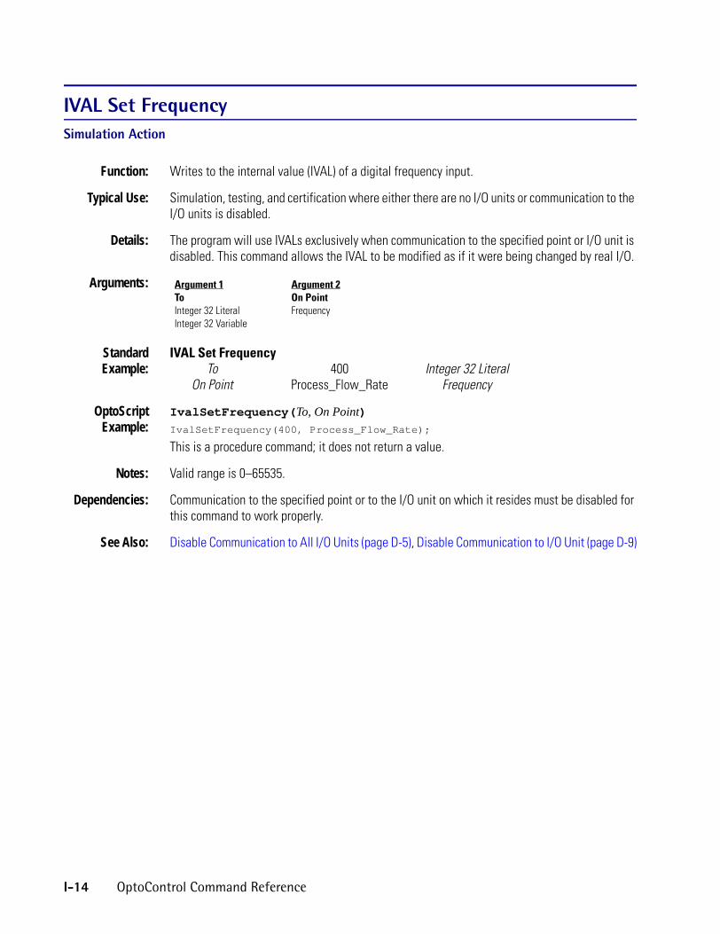
IVAL Set FrequencySimulation Action
Function: Writes to the internal value (IVAL) of a digital frequency input.
Typical Use: Simulation, testing, and certification where either there are no I/O units or communication to the I/O units is disabled.
Details: The program will use IVALs exclusively when communication to the specified point or I/O unit is disabled. This command allows the IVAL to be modified as if it were being changed by real I/O.
Arguments:
StandardExample:
IVAL Set FrequencyTo 400 Integer 32 Literal
On Point Process_Flow_Rate Frequency
OptoScriptExample:
IvalSetFrequency(To, On Point)IvalSetFrequency(400, Process_Flow_Rate);
This is a procedure command; it does not return a value.
Notes: Valid range is 0–65535.
Dependencies: Communication to the specified point or to the I/O unit on which it resides must be disabled for this command to work properly.
See Also: Disable Communication to All I/O Units (page D-5), Disable Communication to I/O Unit (page D-9)
Argument 1ToInteger 32 LiteralInteger 32 Variable
Argument 2On PointFrequency
I-14 OptoControl Command Reference

IIVAL Set Off-LatchSimulation Action
Function: Writes to the internal value (IVAL) of a digital latch input.
Typical Use: Simulation, testing, and certification where either there are no I/O units or communication to the I/O units is disabled.
Details: • The program will use IVALs exclusively when communication to the specified point or I/O unit is disabled. This command allows the IVAL to be modified as if it were being changed by real I/O.
• Any non-zero value sets the latch; zero clears the latch.
Arguments:
StandardExample:
IVAL Set Off-LatchTo -1 Integer 32 Literal
On Point Process_Stop_Button Digital Input
OptoScriptExample:
IvalSetOffLatch(To, On Point)IvalSetOffLatch(-1, Process_Stop_Button);
This is a procedure command; it does not return a value.
Dependencies: Communication to the specified point or to the I/O unit on which it resides must be disabled for this command to work properly.
See Also: Disable Communication to All I/O Units (page D-5), Disable Communication to I/O Unit (page D-9)
Argument 1ToInteger 32 LiteralInteger 32 Variable
Argument 2On PointDigital Input
OptoControl Command Reference I-15
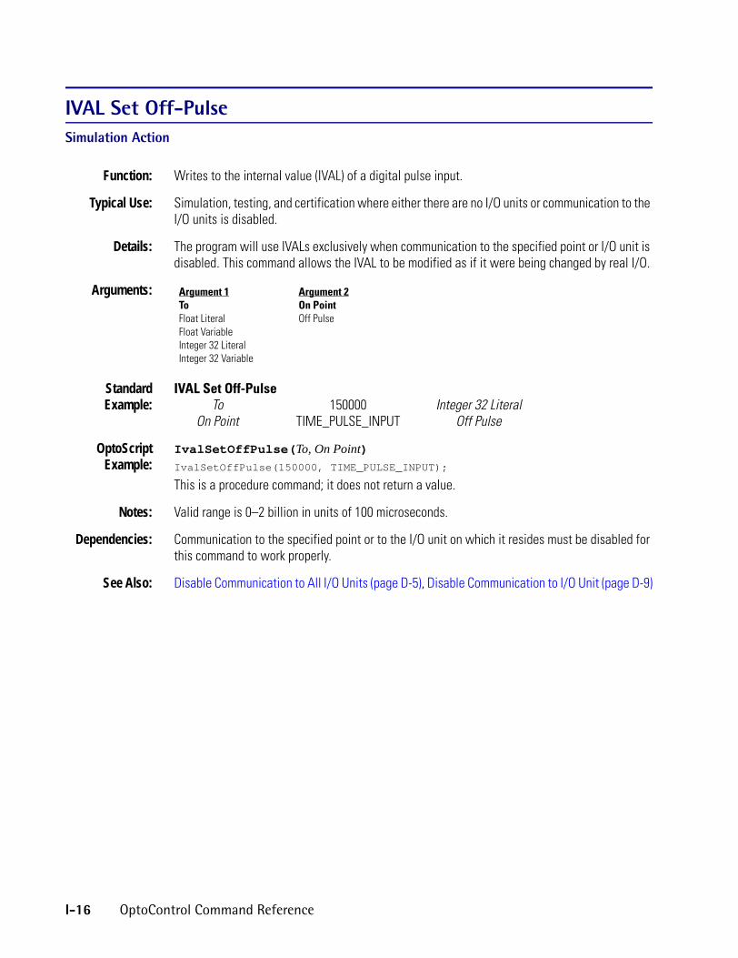
IVAL Set Off-PulseSimulation Action
Function: Writes to the internal value (IVAL) of a digital pulse input.
Typical Use: Simulation, testing, and certification where either there are no I/O units or communication to the I/O units is disabled.
Details: The program will use IVALs exclusively when communication to the specified point or I/O unit is disabled. This command allows the IVAL to be modified as if it were being changed by real I/O.
Arguments:
StandardExample:
IVAL Set Off-PulseTo 150000 Integer 32 Literal
On Point TIME_PULSE_INPUT Off Pulse
OptoScriptExample:
IvalSetOffPulse(To, On Point)IvalSetOffPulse(150000, TIME_PULSE_INPUT);
This is a procedure command; it does not return a value.
Notes: Valid range is 0–2 billion in units of 100 microseconds.
Dependencies: Communication to the specified point or to the I/O unit on which it resides must be disabled for this command to work properly.
See Also: Disable Communication to All I/O Units (page D-5), Disable Communication to I/O Unit (page D-9)
Argument 1ToFloat LiteralFloat VariableInteger 32 LiteralInteger 32 Variable
Argument 2On PointOff Pulse
I-16 OptoControl Command Reference

IIVAL Set Off-TotalizerSimulation Action
Function: Writes to the internal value (IVAL) of a digital totalizer input.
Typical Use: Simulation, testing, and certification where either there are no I/O units or communication to the I/O units is disabled.
Details: The program will use IVALs exclusively when communication to the specified point or I/O unit is disabled. This command allows the IVAL to be modified as if it were being changed by real I/O.
Arguments:
StandardExample:
IVAL Set Off-TotalizerTo 36000000 Integer 32 Literal
On Point PUMP_OFF_TIME Totalizer Off
OptoScriptExample:
IvalSetOffTotalizer(To, On Point)IvalSetOffTotalizer(36000000, PUMP_OFF_TIME);
This is a procedure command; it does not return a value.
Notes: Valid range is 0–2 billion in units of 100 microseconds.
Dependencies: Communication to the specified point or to the I/O unit on which it resides must be disabled for this command to work properly.
See Also: Disable Communication to All I/O Units (page D-5), Disable Communication to I/O Unit (page D-9)
Argument 1ToFloat LiteralFloat VariableInteger 32 LiteralInteger 32 Variable
Argument 2On PointOff Totalizer
OptoControl Command Reference I-17

IVAL Set On-LatchSimulation Action
Function: Writes to the internal value (IVAL) of a digital latch input.
Typical Use: Simulation, testing, and certification where either there are no I/O units or communication to the I/O units is disabled.
Details: • The program will use IVALs exclusively when communication to the specified point or I/O unit is disabled. This command allows the IVAL to be modified as if it were being changed by real I/O.
• Any non-zero value sets the latch; zero clears the latch.
Arguments:
StandardExample:
IVAL Set On-LatchTo 0 Integer 32 Literal
On Point Process_Start_Button Digital Input
OptoScriptExample:
IvalSetOnLatch(To, On Point)IvalSetOnLatch(0, Process_Start_Button);
This is a procedure command; it does not return a value.
Dependencies: Communication to the specified point or to the I/O unit on which it resides must be disabled for this command to work properly.
See Also: Disable Communication to All I/O Units (page D-5), Disable Communication to I/O Unit (page D-9)
Argument 1ToInteger 32 LiteralInteger 32 Variable
Argument 2On PointDigital Input
I-18 OptoControl Command Reference

IIVAL Set On-PulseSimulation Action
Function: Writes to the internal value (IVAL) of a digital pulse input.
Typical Use: Simulation, testing, and certification where either there are no I/O units or communication to the I/O units is disabled.
Details: The program will use IVALs exclusively when communication to the specified point or I/O unit is disabled. This command allows the IVAL to be modified as if it were being changed by real I/O.
Arguments:
StandardExample:
IVAL Set On-Pulse To 133300 Integer 32 Literal
On Point TIME_PULSE_INPUT On Pulse
OptoScriptExample:
IvalSetOnPulse(To, On Point)IvalSetOnPulse(133300, TIME_PULSE_INPUT);
This is a procedure command; it does not return a value.
Notes: Valid range is 0–2 billion in units of 100 microseconds.
Dependencies: Communication to the specified point or to the I/O unit on which it resides must be disabled for this command to work properly.
See Also: Disable Communication to All I/O Units (page D-5), Disable Communication to I/O Unit (page D-9)
Argument 1ToFloat LiteralFloat VariableInteger 32 LiteralInteger 32 Variable
Argument 2On PointOn Pulse
OptoControl Command Reference I-19

IVAL Set On-TotalizerSimulation Action
Function: Writes to the internal value (IVAL) of a digital totalizer input.
Typical Use: Simulation, testing, and certification where either there are no I/O units or communication to the I/O units is disabled.
Details: The program will use IVALs exclusively when communication to the specified point or I/O unit is disabled. This command allows the IVAL to be modified as if it were being changed by real I/O.
Arguments:
StandardExample:
IVAL Set On-TotalizerTo 72000000 Integer 32 Literal
On Point PUMP_ON_TIME On Totalizer
OptoScriptExample:
IvalSetOnTotalizer(To, On Point)IvalSetOnTotalizer(72000000, PUMP_ON_TIME);
This is a procedure command; it does not return a value.
Notes: Valid range is 0–2 billion in units of 100 microseconds.
Dependencies: Communication to the specified point or to the I/O unit on which it resides must be disabled for this command to work properly.
See Also: Disable Communication to All I/O Units (page D-5), Disable Communication to I/O Unit (page D-9)
Argument 1ToFloat LiteralFloat VariableInteger 32 LiteralInteger 32 Variable
Argument 2On PointOn Totalizer
I-20 OptoControl Command Reference

IIVAL Set PeriodSimulation Action
Function: Writes to the internal value (IVAL) of a digital input configured to measure a time period.
Typical Use: Simulation, testing, and certification where either there are no I/O units or communication to the I/O units is disabled.
Details: The program will use IVALs exclusively when communication to the specified point or I/O unit is disabled. This command allows the IVAL to be modified as if it were being changed by real I/O.
Arguments:
StandardExample:
IVAL Set PeriodTo 5.63 Float Literal
On Point Pump_On_Time Period
OptoScriptExample:
IvalSetPeriod(To, On Point)IvalSetPeriod(5.63, Pump_On_Time);
This is a procedure command; it does not return a value.
Notes: Value to write is in seconds.
Dependencies: Communication to the specified point or to the I/O unit on which it resides must be disabled for this command to work properly.
See Also: Get Period (page G-80), Disable Communication to All I/O Units (page D-5), Disable Communication to I/O Unit (page D-9)
Argument 1ToFloat LiteralFloat VariableInteger 32 LiteralInteger 32 Variable
Argument 2On PointPeriod
OptoControl Command Reference I-21

IVAL Set PID Control WordSimulation Action
Function: Writes to the internal value (IVAL) of the bits that represent the PID configuration.
Typical Use: Simulation, testing, and certification where either there are no I/O units or communication to the I/O units is disabled.
Details: Bit assignments:11 1 = Use SqRt value from input channel.10 1 = Setpoint was above high clamp. Write zero to clear.9 1 = Setpoint was below low clamp. Write zero to clear.8 1 = Input channel under-range. Write zero to clear.7 1 = Loop active. 0 = Loop stopped.6 1 = Loop in auto mode. 0 = Loop in manual mode.5 1 = Output active. 0 = Output disconnected.4 1 = Output tracks input in manual mode. 0 = no action.3 1 = Setpoint tracks input in manual mode. 0 = no action.2 1 = Input from host. 0 = Input from channel.1 1 = Setpoint from channel. 0 = Setpoint from host.0 1 = Use filtered value from input channel. Must have filtering active on the input channel.
0 = Use current value of input channel.To set any bit(s) put a 1 for each bit to set in the MOMO On parameter. To clear any bit(s) put a 1 for each bit to clear in the MOMO Off parameter. All MOMO bit positions with zeros will leave the corresponding PID control word bit unchanged.
Arguments:
StandardExample:
IVAL Set PID Control WordOn Mask PID_CTRL_SET Integer 32 VariableOff Mask PID_CTRL_CLEAR Integer 32 Variable
For PID Loop EXTRUDER_ZONE08 PID Loop
OptoScriptExample:
IvalSetPidControlWord(On Mask, Off Mask, For PID Loop)IvalSetPidControlWord(PID_CTRL_SET, PID_CTRL_CLEAR, EXTRUDER_ZONE08);
This is a procedure command; it does not return a value.
Dependencies: Communication to the specified point or to the I/O unit on which it resides must be disabled for this command to work properly.
See Also: Disable Communication to All I/O Units (page D-5), Disable Communication to I/O Unit (page D-9)
Argument 1On MaskInteger 32 LiteralInteger 32 Variable
Argument 2Off MaskInteger 32 LiteralInteger 32 Variable
Argument 3For PID LoopPID Loop
I-22 OptoControl Command Reference

IIVAL Set PID Process TermSimulation Action
Function: Writes to the internal value (IVAL) of a PID input.
Typical Use: Simulation, testing, and certification where either there are no I/O units or communication to the I/O units is disabled.
Details: The program will use IVALs exclusively when communication to the specified point or I/O unit is disabled. This command allows the IVAL to be modified as if it were being changed by real I/O.
Arguments:
StandardExample:
IVAL Set PID Process TermTo 1500 Integer 32 Literal
On PID Loop Influent_Flow_Controller PID Loop
OptoScriptExample:
IvalSetPidProcessTerm(To, On PID Loop)IvalSetPidProcessTerm(1500, Influent_Flow_Controller);
This is a procedure command; it does not return a value.
Notes: Valid range is equal to the scaling of the PID input channel.
Dependencies: Communication to the specified PID or to the I/O unit on which it resides must be disabled for this command to work properly.
See Also: Disable Communication to All I/O Units (page D-5), Disable Communication to I/O Unit (page D-9)
Argument 1ToFloat LiteralFloat VariableInteger 32 LiteralInteger 32 Variable
Argument 2On PID LoopPID Loop
OptoControl Command Reference I-23

IVAL Set Quadrature CounterSimulation Action
Function: Writes to the internal value (IVAL) of a digital quadrature counter input.
Typical Use: Simulation, testing, and certification where either there are no I/O units or communication to the I/O units is disabled.
Details: The program will use IVALs exclusively when communication to the specified point or I/O unit is disabled. This command allows the IVAL to be modified as if it were being changed by real I/O.
Arguments:
StandardExample:
IVAL Set Quadrature CounterTo 63489 Integer 32 Literal
On Point Process_Flow_Total Quadrature Counter
OptoScriptExample:
IvalSetQuadratureCounter(To, On Point)IvalSetQuadratureCounter(63489, Process_Flow_Total);
This is a procedure command; it does not return a value.
Notes: Valid range is 0 to ±2 billion.
Dependencies: Communication to the specified point or to the I/O unit on which it resides must be disabled for this command to work properly.
See Also: Disable Communication to All I/O Units (page D-5), Disable Communication to I/O Unit (page D-9)
Argument 1ToInteger 32 LiteralInteger 32 Variable
Argument 2On PointQuadrature Counter
I-24 OptoControl Command Reference

IIVAL Set TPO PercentSimulation Action
Function: Writes to the internal value (IVAL) of a digital TPO output.
Typical Use: Simulation, testing, and certification where either there are no I/O units or communication to the I/O units is disabled.
Details: The program will use IVALs exclusively when communication to the specified point or I/O unit is disabled. This command allows the IVAL to be modified as if it were being changed by real I/O.
Arguments:
StandardExample:
IVAL Set TPO PercentTo 43.66 Float Literal
On Point ZONE_3_HEATER TPO
OptoScriptExample:
IvalSetTpoPercent(To, On Point)IvalSetTpoPercent(43.66, ZONE_3_HEATER);
This is a procedure command; it does not return a value.
Notes: Valid range is 0.0 to 100.0.
Dependencies: Communication to the specified TPO or to the I/O unit on which it resides must be disabled for this command to work properly.
See Also: Disable Communication to All I/O Units (page D-5), Disable Communication to I/O Unit (page D-9)
Argument 1ToFloat LiteralFloat VariableInteger 32 LiteralInteger 32 Variable
Argument 2On PointTPO
OptoControl Command Reference I-25

IVAL Set TPO PeriodSimulation Action
Function: Writes to the internal value (IVAL) of a digital TPO period.
Typical Use: Simulation, testing, and certification where either there are no I/O units or communication to the I/O units is disabled.
Details: The program will use IVALs exclusively when communication to the specified point or I/O unit is disabled. This command allows the IVAL to be modified as if it were being changed by real I/O.
Arguments:
StandardExample:
IVAL Set TPO PeriodValue 1.00 Float Literal
To ZONE_3_HEATER TPO
OptoScriptExample:
IvalSetTpoPeriod(Value, On Point)IvalSetTpoPeriod(1.00, ZONE_3_HEATER);
This is a procedure command; it does not return a value.
Notes: Valid range is 0.1 to 429,496.7 seconds with resolution to 100 microseconds.
Dependencies: Communication to the specified TPO or to the I/O unit on which it resides must be disabled for this command to work properly.
See Also: Disable Communication to All I/O Units (page D-5), Disable Communication to I/O Unit (page D-9)
Argument 1ValueFloat LiteralFloat VariableInteger 32 LiteralInteger 32 Variable
Argument 2ToTPO
I-26 OptoControl Command Reference

IIVAL Turn OffSimulation Action
Function: Writes to the internal value (IVAL) of a digital input.
Typical Use: Simulation, testing, and certification where either there are no I/O units or communication to the I/O units is disabled.
Details: The program will use IVALs exclusively when communication to the specified point or I/O unit is disabled. This command allows the IVAL to be modified as if it were being changed by real I/O.
Arguments:
StandardExample:
IVAL Turn OffProcess_Start_Button Digital Input
OptoScriptExample:
IvalTurnOff(Point)IvalTurnOff(Process_Start_Button);
This is a procedure command; it does not return a value.
Notes: Turns Off the IVAL for the specified point.
Dependencies: Communication to the specified point or to the I/O unit on which it resides must be disabled for this command to work properly.
See Also: Disable Communication to All I/O Units (page D-5), Disable Communication to I/O Unit (page D-9)
Argument 1[Value]Digital InputDigital OutputLocal Simple Digital InputLocal Simple Digital Output
OptoControl Command Reference I-27

IVAL Turn OnSimulation Action
Function: Writes to the internal value (IVAL) of a digital input.
Typical Use: Simulation, testing, and certification where either there are no I/O units or communication to the I/O units is disabled.
Details: The program will use IVALs exclusively when communication to the specified point or I/O unit is disabled. This command allows the IVAL to be modified as if it were being changed by real I/O.
Arguments:
StandardExample:
IVAL Turn OnPROCESS_START_BUTTON Digital Input
OptoScriptExample:
IvalTurnOn(Point)IvalTurnOn(Process_Start_Button);
This is a procedure command; it does not return a value.
Notes: Turns On the IVAL for the specified point.
Dependencies: Communication to the specified point or to the I/O unit on which it resides must be disabled for this command to work properly.
See Also: Disable Communication to All I/O Units (page D-5), Disable Communication to I/O Unit (page D-9)
Argument 1[Value]Digital InputDigital OutputLocal Simple Digital InputLocal Simple Digital Output
I-28 OptoControl Command Reference

L
LLess?Logical ConditionFunction: To determine if one numeric value is less than another.
Typical Use: To determine if a value is too low.
Details: • Determines if Argument 1 is less than Argument 2. Examples:Argument 1 Argument 2 Result
0 0 False-1 0 True-1 -3 False
22.221 22.220 False
• Evaluates True if the first value is less than the second, False otherwise.
Arguments:
StandardExample:
Is TANK_LEVEL Analog InputLess?
Than FILL_SETPOINT Float Variable
OptoScriptExample:
OptoScript doesn’t use a command; the function is built in. Use the < operator. if (TANK_LEVEL < FILL_SETPOINT) then
Argument 1IsAnalog InputAnalog OutputCounterDigital InputDigital OutputDown Timer VariableFloat LiteralFloat VariableFrequencyInteger 32 LiteralInteger 32 VariableInteger 64 LiteralInteger 64 VariableLocal Simple Digital InputLocal Simple Digital OutputOff PulseOff TotalizerOn PulseOn TotalizerPeriodQuadrature CounterUp Timer Variable
Argument 2ThanAnalog InputAnalog OutputCounterDigital InputDigital OutputDown Timer VariableFloat LiteralFloat VariableFrequencyInteger 32 LiteralInteger 32 VariableInteger 64 LiteralInteger 64 VariableLocal Simple Digital InputLocal Simple Digital OutputOff PulseOff TotalizerOn PulseOn TotalizerPeriodQuadrature CounterUp Timer Variable
OptoControl Command Reference L-1

Notes: • See “Logical Commands” in Chapter 10 of the OptoControl User’s Guide. The example shown is only one of many ways to use the < operator. For more information on comparison operators in OptoScript code, see Chapter 11 of the OptoControl User’s Guide.
• Use Within Limits? to test for an approximate match.• To test for greater than or equal to, use either Greater Than or Equal? or the False exit.
See Also: Greater? (page G-106), Not Equal? (page N-4), Greater Than or Equal? (page G-107), Equal? (page E-16)
Less Than or Equal?Logical Condition
Function: To determine if one numeric value is less than or equal to another.
Typical Use: To determine if a value is too low.
Details: • Determines if Argument 1 is less than or equal to Argument 2. Examples:Argument 1 Argument 2 Result
0 0 True-1 0 True-1 -3 False
22.221 22.220 False
• Evaluates True if the first value is less than or equal to the second, False otherwise.
Arguments: Argument 1IsAnalog InputAnalog OutputCounterDigital InputDigital OutputDown Timer VariableFloat LiteralFloat VariableFrequencyInteger 32 LiteralInteger 32 VariableInteger 64 LiteralInteger 64 VariableLocal Simple Digital InputLocal Simple Digital OutputOff PulseOff TotalizerOn PulseOn TotalizerPeriodQuadrature CounterUp Timer Variable
Argument 2ToAnalog InputAnalog OutputCounterDigital InputDigital OutputDown Timer VariableFloat LiteralFloat VariableFrequencyInteger 32 LiteralInteger 32 VariableInteger 64 LiteralInteger 64 VariableLocal Simple Digital InputLocal Simple Digital OutputOff PulseOff TotalizerOn PulseOn TotalizerPeriodQuadrature CounterUp Timer Variable
L-2 OptoControl Command Reference

LStandardExample:
Is TEMPERATURE Float VariableLess Than or Equal?
To 98.60 Float Literal
OptoScriptExample:
OptoScript doesn’t use a command; the function is built in. Use the <= operator. if (TEMPERATURE <= 98.60) then
Notes: • See “Logical Commands” in Chapter 10 of the OptoControl User’s Guide. The example shown is only one of many ways to use the < operator. For more information on comparison operators in OptoScript code, see Chapter 11 of the OptoControl User’s Guide.
• Use Within Limits? to test for an approximate match.• To test for greater than, use either the Greater? condition or the False exit.
See Also: Greater? (page G-106), Not Equal? (page N-4), Greater Than or Equal? (page G-107), Within Limits? (page W-1)
Less Than or Equal to Table Element?Logical Condition
Function: To determine if a numeric value is less than or equal to a specified value in a float or integer table.
Typical Use: To store low values.
Details: • Determines if one value (Argument 1) is less than or equal to another (a value at index Argument 2 in float or integer table Argument 3). Examples:
Value 1 Value 2 Result0.0 0.0 True
0.0001 0.0 False22.22 22.222 True
-32768 -32767 True22221 2222 False
• Evaluates True if the first value is less than or equal to the second, False otherwise.
OptoControl Command Reference L-3

Arguments:
StandardExample:
Is THIS_READING Float VariableLess Than or Equal to Table Element?
At Index TABLE_INDEX Integer 32 VariableOf Table TABLE_OF_READINGS Float Table
OptoScriptExample:
OptoScript doesn’t use a command; the function is built in. Use the <= operator. if (THIS_READING <= TABLE_OF_READINGS[TABLE_INDEX]) then
Notes: • See “Logical Commands” in Chapter 10 of the OptoControl User’s Guide. The example shown is only one of many ways to use the <= operator. For more information on comparison operators in OptoScript code, see Chapter 11 of the OptoControl User’s Guide.
• To test for greater than, use either Greater Than Table Element? or the False exit.
Queue Errors: 32 = Bad table index value—index was negative or greater than or equal to the table size.
See Also: Greater Than Table Element? (page G-109), Not Equal to Table Element? (page N-5), Greater Than or Equal to Table Element? (page G-108), Equal to Table Element? (page E-18)
Argument 1IsAnalog InputAnalog OutputCounterDigital InputDigital OutputDown Timer VariableFloat LiteralFloat VariableFrequencyInteger 32 LiteralInteger 32 VariableInteger 64 LiteralInteger 64 VariableLocal Simple Digital InputLocal Simple Digital OutputOff PulseOff TotalizerOn PulseOn TotalizerPeriodQuadrature CounterUp Timer Variable
Argument 2At IndexInteger 32 LiteralInteger 32 Variable
Argument 3Of TableFloat TableInteger 32 TableInteger 64 Table
L-4 OptoControl Command Reference

LLess Than Table Element?Logical Condition
Function: To determine if a numeric value is less than a specified value in a float or integer table.
Typical Use: To store low values.
Details: • Determines if one value (Argument 1) is less than another (a value at index Argument 2 in float or integer table Argument 3). Examples:
Value 1 Value 2 Result0.0 0.0 False
0.0001 0.0 False-98.766 -98.765 True-32768 -32767 True22221 2222 False
• Evaluates True if the first value is less than the second, False otherwise.
Arguments:
StandardExample:
Is THIS_READING Float VariableLess Than Table Element?
At Index TABLE_INDEX Integer 32 VariableOf Table TABLE_OF_READINGS Float Table
OptoScriptExample:
OptoScript doesn’t use a command; the function is built in. Use the < operator.if (THIS_READING < TABLE_OF_READINGS[TABLE_INDEX]) then
Argument 1IsAnalog InputAnalog OutputCounterDigital InputDigital OutputDown Timer VariableFloat LiteralFloat VariableFrequencyInteger 32 LiteralInteger 32 VariableInteger 64 LiteralInteger 64 VariableLocal Simple Digital InputLocal Simple Digital OutputOff PulseOff TotalizerOn PulseOn TotalizerPeriodQuadrature CounterUp Timer Variable
Argument 2At IndexInteger 32 LiteralInteger 32 Variable
Argument 3Of TableFloat TableInteger 32 TableInteger 64 Table
OptoControl Command Reference L-5

Notes: • See “Logical Commands” in Chapter 10 of the OptoControl User’s Guide. The example shown is only one of many ways to use the < operator. For more information on comparison operators in OptoScript code, see Chapter 11 of the OptoControl User’s Guide.
To test for greater than or equal to, use either Greater Than or Equal to Table Element? or the False exit.
Queue Errors: 32 = Bad table index value—index was negative or greater than or equal to table size.
See Also: Greater Than Table Element? (page G-109), Not Equal to Table Element? (page N-5), Greater Than or Equal to Table Element? (page G-108), Equal to Table Element? (page E-18)
Low RAM Backup Battery?Controller Condition
Function: To determine if the battery backing up the static RAM on the controller is weak.
Typical Use: To determine if the battery needs to be replaced.
Details: Evaluates True if the voltage for the battery backing up static RAM is low, False otherwise.
Arguments: None.
StandardExample:
Low RAM Backup Battery?
OptoScriptExample:
IsRamBackupBatteryLow()if (IsRamBackupBatteryLow()) then
This is a function command; it returns a value of true (non-zero) or false (0). The returned value can be consumed by a control structure (as in the example shown) or by a variable, I/O point, etc. See Chapter 11 of the OptoControl User’s Guide for more information.
Notes: On the LC32, if the keypad (port 5) is in use by a chart, this condition will return False.
Queue Errors: 39 = Port already in use—LC32 keypad (port 5) is in use by another chart.29 = Timeout—LC32 keypad (port 5) does not respond.
See Also: Get RTU/M4IO Voltage (page G-97)
L-6 OptoControl Command Reference

M
MMake Integer 64Logical ActionFunction: To combine two 32-bit integers into a single 64-bit integer.
Typical Use: To put the two halves of a 64-bit integer back together after separating them for faster individual manipulation.
Details: • Places one 32-bit integer in the upper half of a 64-bit integer and the other 32-bit integer in the lower half.
• When the integer 64 is made, the least significant bit corresponds to point zero and the most significant bit corresponds to point 64 on a 64-point digital rack.
Arguments:
StandardExample:
Make Integer 64High Integer IN_BD2_HIGH Integer 32 VariableLow Integer IN_BD2_LOW Integer 32 Variable
Put in IN_BD2_STATUS Integer 64 Variable
OptoScriptExample:
MakeInt64(High Integer, Low Integer)IN_BD2_STATUS = MakeInt64(IN_BD2_HIGH, IN_BD2_LOW);
This is a function command; it returns the 64-bit integer. The returned value can be consumed by a variable (as shown) or by another item, such as a mathematical expression or a control structure. It cannot be consumed by an I/O unit, however. See Chapter 11 of the OptoControl User’s Guide for more information on OptoScript. Although the returned value cannot be consumed by an I/O unit, you can accomplish the same thing by using OptoScript code such as the following:nnTemp1 = MakeInt64(nHiPart, nLoPart);
SetDigital64IoUnitFromMomo(nnTemp1, bitnot nnTemp1, MyDig64);
Notes: This command is useful if you want to get information from a program that doesn’t directly support 64-bit integers, such as OptoDisplay, OptoServer, and third-party products, and use that information in a digital-only SNAP-ENET-D64 Ethernet I/O brain.
See Also: Get High Bits of Integer 64 (page G-58), Get Low Bits of Integer 64 (page G-63)
Argument 1High IntegerInteger 32 LiteralInteger 32 Variable
Argument 2Low IntegerInteger 32 LiteralInteger 32 Variable
Argument 3Put inInteger 64 VariableSNAP Digital 64*
* Standard commands only
OptoControl Command Reference M-1

MaximumMathematical Action
Function: To select the greater of two values.
Typical Use: To select the higher pressure or temperature reading.
Details: The greater of the two values is selected.
Arguments:
StandardExample:
MaximumCompare Pressure_A Analog Input
With Pressure_B Analog InputPut Maximum in Highest_Pressure Float Variable
OptoScriptExample:
Max(Compare, With)Highest_Pressure = Max(Pressure_A, Pressure_B);
This is a function command; it returns the greater of the two values. The returned value can be consumed by a variable (as shown) or by another item, such as a mathematical expression or a control structure. See Chapter 11 of the OptoControl User’s Guide for more information.
See Also: Minimum (page M-3)
Argument 1CompareAnalog InputAnalog OutputDown Timer VariableFloat LiteralFloat VariableInteger 32 LiteralInteger 32 VariableInteger 64 LiteralInteger 64 VariableUp Timer Variable
Argument 2WithAnalog InputAnalog OutputDown Timer VariableFloat LiteralFloat VariableInteger 32 LiteralInteger 32 VariableInteger 64 LiteralInteger 64 VariableUp Timer Variable
Argument 3Put Maximum inAnalog OutputDown Timer VariableFloat VariableInteger 32 VariableInteger 64 VariableUp Timer Variable
M-2 OptoControl Command Reference

MMinimumMathematical Action
Function: To select the lesser of two values.
Typical Use: To select the lower pressure or temperature reading.
Details: The lesser of the two values is selected.
Arguments:
StandardExample:
MinimumCompare Pressure_A Analog Input
With Pressure_B Analog InputPut Minimum in Lowest_Pressure Float Variable
OptoScriptExample:
Min(Compare, With)Lowest_Pressure = Min(Pressure_A, Pressure_B);
This is a function command; it returns the lesser value. The returned value can be consumed by a variable (as shown) or by another item, such as a mathematical expression or a control structure. See Chapter 11 of the OptoControl User’s Guide for more information.
See Also: Maximum (page M-2)
Argument 1CompareAnalog InputAnalog OutputDown Timer VariableFloat LiteralFloat VariableInteger 32 LiteralInteger 32 VariableInteger 64 LiteralInteger 64 VariableUp Timer Variable
Argument 2WithAnalog InputAnalog OutputDown Timer VariableFloat LiteralFloat VariableInteger 32 LiteralInteger 32 VariableInteger 64 LiteralInteger 64 VariableUp Timer Variable
Argument 3Put Minimum inAnalog OutputDown Timer VariableFloat VariableInteger 32 VariableInteger 64 VariableUp Timer Variable
OptoControl Command Reference M-3

ModuloMathematical Action
Function: To generate the remainder resulting from integer division.
Typical Use: To capture the remainder whenever integer modulo calculations are needed.
Details: • Always results in an integer value. Examples: 40 modulo 16 = 8, 8 modulo 8 = 0.• If any arguments are floats, they are rounded to integers before the division occurs.
Arguments:
StandardExample:
ModuloNum_Parts_Produced Integer 32 Variable
By Minutes_Elapsed Integer 32 VariablePut Result in Productivity_Remainder Integer 32 Variable
OptoScriptExample:
OptoScript doesn’t use a command; the function is built in. Use the % operator.Productivity_Remainder = Num_Parts_Produced % Minutes_Elapsed;
Notes: • See “Mathematical Commands” in Chapter 10 of the OptoControl User’s Guide. • In OptoScript code, the % operator can be used in several ways. For more information on
mathematical expressions in OptoScript code, see Chapter 11 of the OptoControl User’s Guide.
See Also: Divide (page D-21), Multiply (page M-27)
Argument 1[Value]Analog InputAnalog OutputDown Timer VariableFloat LiteralFloat VariableInteger 32 LiteralInteger 32 VariableInteger 64 LiteralInteger 64 VariableUp Timer Variable
Argument 2ByAnalog InputAnalog OutputDown Timer VariableFloat LiteralFloat VariableInteger 32 LiteralInteger 32 VariableInteger 64 LiteralInteger 64 VariableUp Timer Variable
Argument 3Put Result inAnalog OutputDown Timer VariableFloat VariableInteger 32 VariableInteger 64 VariableUp Timer Variable
M-4 OptoControl Command Reference

MMoveMiscellaneous Action
Function: To copy a digital, analog, or numeric value to another location.
Typical Use: To copy values between objects, even if they are dissimilar types.
Details: OptoControl automatically converts the type of Argument 1 to match that of Argument 2. The following rules are employed when copying values between objects of different types:• From Float to Integer: Floats are rounded up for fractions of 0.5 or greater, otherwise they
are rounded down.• From Integer to Float: Integer values are converted directly to floats.• From Digital Input or Output: A value of -1 is returned for on, 0 for off.• From Latch: A value of -1 is returned for set latches, 0 for latches that are not set.• To Digital Output: A value of 0 turns the output off. Any non-zero value turns the output on.• To Analog Output: Values are sent as is. Expect some rounding consistent with the analog
resolution of the I/O unit. If the value sent is outside the allowable range for the point, the output will go to the nearest range limit, either zero or full scale.
Arguments:
StandardExample:
MoveFrom DIG1 Digital Input
To DIG1_STATUS Integer 32 Variable
OptoScriptExample:
OptoScript doesn’t use a command; the function is built in. Use the = operator.DIG1_STATUS = DIG1;
Argument 1FromAnalog InputAnalog OutputCounterDigital InputDigital OutputDown Timer VariableFloat LiteralFloat VariableFrequencyInteger 32 LiteralInteger 32 VariableInteger 64 LiteralInteger 64 VariableLocal Simple Digital InputLocal Simple Digital OutputOff PulseOff TotalizerOn PulseOn TotalizerPeriodQuadrature CounterUp Timer Variable
Argument 2ToAnalog OutputDigital OutputDown Timer VariableFloat VariableInteger 32 VariableInteger 64 VariableLocal Simple Digital OutputTPOUp Timer Variable
OptoControl Command Reference M-5

Notes: • In OptoScript code, simply make assignments where you would use the Move command.• After you move a new value to an analog output, anywhere from 0–50 milliseconds will
elapse before the analog output is actually updated. Reading the output value during this period will show the previous value. This limitation may be improved in future versions of analog I/O units.
• You can use Move with timers as the equivalent of two other commands: – With up timers, Move is the same as using Set Up Timer Target Value and Start Timer.
The value moved is the target value, and it overwrites any target value already in place. The up timer starts immediately from zero.
– With down timers, Move is the same as using Set Down Timer Preset Value and Start Timer. The value moved is the preset value the timer will start from, and it overwrites any preset value previously set. The timer starts immediately from the preset value.
Queue Errors: 33 = Overflow error—integer or float value was too large.
See Also: Move String (page M-15), and all Move to or Move from Table commands.
Move 32 BitsLogical Action
Function: To move the internal bit pattern of an integer 32 into a float, or to move a float into an integer 32.
Typical Use: To help parse or create binary data when communicating with other devices.
Arguments:
StandardExample:
Move 32 BitsFrom Source_Data Integer 32 Variable
To Float Float Variable
OptoScriptExample:
Move32Bits(From, To)Move32Bits(Source_Data, Float);
This is a procedure command; it does not return a value.
Notes: See “Logical Commands” in Chapter 10 of the OptoControl User’s Guide.
Argument 1FromFloat LiteralFloat VariableInteger 32 LiteralInteger 32 Variable
Argument 2ToFloat VariableInteger 32 Variable
M-6 OptoControl Command Reference

MMove Analog I/O Unit to TableI/O Unit Action
Function: To read all 16 points of an analog I/O unit and move the returned values to a float table (of 16 elements or more).
Typical Use: To efficiently read all 16 points of analog data on a single I/O unit with one command.
Details: • This command is four times faster than using Move 16 times.• Reads both inputs and outputs.• Updates the IVALs and XVALs for all 16 points.• Transfers 16 points of float data (in engineering units) from the analog I/O unit to a float
table beginning at the index specified. If there are fewer than 16 elements of data from the specified index to the end of the table, no data will be written to the table and a 32 will be placed in the error queue.
• Points that are not configured will return a value of 0.0.• If a specific point is disabled or if the entire I/O unit is disabled, only the internal values
(IVALs) will be read.
Arguments:
StandardExample:
Move Analog I/O Unit to TableFrom ANALOG_UNIT_255 G4 Analog Multifunction I/O Unit
To Index 2 Integer 32 LiteralOf Table DATA_TABLE Float Table
OptoScriptExample:
MoveAnalogIoUnitToTable(I/O Unit, To Index, Of Table)MoveAnalogIoUnitToTable(ANALOG_UNIT_255, 2, DATA_TABLE);
This is a procedure command; it does not return a value.
Notes: To speed up analog logic execution, use Disable Communication to I/O Unit after this command. This forces all references to points on the I/O unit to use IVAL data rather than getting data from the I/O unit one point at a time. If this procedure is followed, use Enable Communication to I/O Unit before using this command again. See Notes under Move Table to Analog I/O Unit for more information.
Queue Errors: 32 = Bad table index value—index was negative or greater than or equal to the table size.
See Also: Move Table to Analog I/O Unit (page M-17)
Argument 1FromB200 Analog Multifunction I/O UnitB3000 SNAP AnalogG4 Analog Multifunction I/O UnitHRD Analog Current Output I/O UnitHRD Analog RTD Input I/O UnitHRD Analog Thermocouple/mV Input I/O UnitHRD Analog Voltage Output I/O UnitHRD Analog Voltage/Current Input I/O Unit
Argument 2To IndexInteger 32 LiteralInteger 32 Variable
Argument 3Of TableFloat Table
OptoControl Command Reference M-7

Move Digital I/O Unit to TableI/O Unit Action
Function: To read the current on/off status of all points on the specified digital I/O unit and to move the state of each point into consecutive indices of a table.
Typical Use: To efficiently read the status of all digital points on a single I/O unit with one command.
Details: • Reads the current on/off status of all 16 points on the digital I/O unit specified.• Updates the IVALs and XVALs for all 16 points.• Reads inputs as well as outputs.• If a point is on, there will be a “-1” in the respective table element.• If a point is off, there will be a “0” in the respective table element.• Point 0 corresponds to the beginning table element.• If a specific point is disabled, it will not be read.• If the entire I/O unit is disabled, none of the points will be read.• Returns status to the integer table beginning at the index specified. If there are fewer than
16 elements of data from the specified index to the end of the table, no data will be written to the table and a 32 will be placed in the error queue.
Arguments:
StandardExample:
Move Digital I/O Unit to TableFrom INLET_VALVE_CTRL G4 Digital Multifunction I/O Unit
Starting Index 1 Integer 32 LiteralOf Table IO_STATUS_TABLE Integer 32 Table
OptoScriptExample:
MoveDigitalIoUnitToTable(I/O Unit, Starting Index, Of Table)MoveDigitalIoUnitToTable(INLET_VALVE_CTRL, 1, IO_STATUS_TABLE);
This is a procedure command; it does not return a value.
Notes: In the above example, point 0 of the I/O unit will map to index 1 of the table, point 1 of the I/O unit will map to index 2 of the table, etc. (point 15 of the I/O unit will map to index 16 of the table).
Queue Errors: 32 = Bad table index value—index was negative or greater than the table size.
See Also: Get Digital I/O Unit as Binary Value (page G-48), Move Table to Digital I/O Unit (page M-19)
Argument 1FromB100 Digital Multifunction I/O UnitB3000 SNAP DigitalG4 Digital Local Simple I/O UnitG4 Digital Multifunction I/O UnitG4 Digital Remote Simple I/O UnitSNAP Remote Simple Digital
Argument 2Starting IndexInteger 32 LiteralInteger 32 Variable
Argument 3Of TableInteger 32 Table
M-8 OptoControl Command Reference
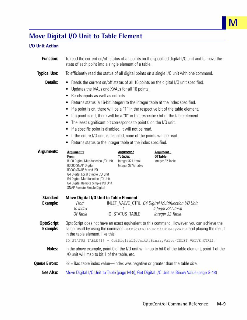
MMove Digital I/O Unit to Table ElementI/O Unit Action
Function: To read the current on/off status of all points on the specified digital I/O unit and to move the state of each point into a single element of a table.
Typical Use: To efficiently read the status of all digital points on a single I/O unit with one command.
Details: • Reads the current on/off status of all 16 points on the digital I/O unit specified.• Updates the IVALs and XVALs for all 16 points.• Reads inputs as well as outputs.• Returns status (a 16-bit integer) to the integer table at the index specified. • If a point is on, there will be a “1” in the respective bit of the table element.• If a point is off, there will be a “0” in the respective bit of the table element.• The least significant bit corresponds to point 0 on the I/O unit.• If a specific point is disabled, it will not be read.• If the entire I/O unit is disabled, none of the points will be read.• Returns status to the integer table at the index specified.
Arguments:
StandardExample:
Move Digital I/O Unit to Table ElementFrom INLET_VALVE_CTRL G4 Digital Multifunction I/O Unit
To Index 1 Integer 32 LiteralOf Table IO_STATUS_TABLE Integer 32 Table
OptoScriptExample:
OptoScript does not have an exact equivalent to this command. However, you can achieve the same result by using the command GetDigitalIoUnitAsBinaryValue and placing the result in the table element, like this:IO_STATUS_TABLE[1] = GetDigitalIoUnitAsBinaryValue(INLET_VALVE_CTRL);
Notes: In the above example, point 0 of the I/O unit will map to bit 0 of the table element, point 1 of the I/O unit will map to bit 1 of the table, etc.
Queue Errors: 32 = Bad table index value—index was negative or greater than the table size.
See Also: Move Digital I/O Unit to Table (page M-8), Get Digital I/O Unit as Binary Value (page G-48)
Argument 1FromB100 Digital Multifunction I/O UnitB3000 SNAP DigitalB3000 SNAP Mixed I/OG4 Digital Local Simple I/O UnitG4 Digital Multifunction I/O UnitG4 Digital Remote Simple I/O UnitSNAP Remote Simple Digital
Argument 2To IndexInteger 32 LiteralInteger 32 Variable
Argument 3Of TableInteger 32 Table
OptoControl Command Reference M-9

Move from Pointer Table ElementPointers Action
Function: To move an object from a pointer table to a pointer variable.
Typical Use: To retrieve objects from pointer tables.
Details: • This command allows you to retrieve objects from a pointer table and place them into pointer variables of the same type.
• Operations cannot be performed on objects from within a pointer table.
Arguments:
StandardExample:
Move From Pointer Table ElementIndex CURRENT_INDEX Integer 32 Variable
Of Table IO_POINTERS Pointer TableTo Pointer TANK_SWITCH Pointer Variable
OptoScriptExample:
OptoScript doesn’t use a command; the function is built in. Use the = operator.TANK_SWITCH = IO_POINTERS[CURRENT_INDEX];
Notes: • In OptoScript code, simply make an assignment from the table element. • Be sure to move the object from the table into a pointer of the same type. If the types are
different, an error will be posted to the error queue.
Queue Errors: 60 = Wrong object type.61 = NULL object error, caused by the table entry at that index being null. Use Move to Pointer Table to initialize the table entry.
See Also: Move to Pointer (page M-23)
Argument 1IndexInteger 32 LiteralInteger 32 Variable
Argument 2Of TablePointer Table
Argument 3To PointerPointer Variable
M-10 OptoControl Command Reference

MMove from String TableString Action
Function: To copy a string from a string table.
Typical Uses: • To create a numeric-to-string lookup table.• To retrieve strings from a table for further processing.
Details: • Quotes (“”) are used for readability only. They are not part of the string. Do not type them or expect to see them.
• Valid range for Index (Argument 1) is zero to the table length - 1 (size - 1).
Arguments:
StandardExample:
The following example performs a numeric-to-string-table lookup. Given the numeric value for the day of week, the command below gets the name of the day of week from a string table. Use Get Day of Week to get the value to use for From Index.
Move from String TableFrom Index INDEX Integer 32 Variable
Of Table STRING_TABLE String TableTo STRING String Variable
The results of this command are as follows:INDEX STRING
0 “SUN”1 “MON”2 “TUE”3 “WED”4 “THU”5 “FRI”6 “SAT”
OptoScriptExample:
OptoScript doesn’t use a command; the function is built in. Use the = operator.STRING = STRING_TABLE[INDEX];
Notes: • See “String Commands” in Chapter 10 of the OptoControl User’s Guide.• In OptoScript code, simply make an assignment to the string. • A string table is a good way to correlate a number to a string.• Use Move to String Table or the Init utility to load the table with data.• Multiple string tables can be used to create small databases of information. For example,
one string table could contain a product name and another could contain the product ID code or barcode. It is essential to keep all related information at the same Index in each table.
Queue Errors: 32 = Bad table index value—index was negative or greater than or equal to the table size.
See Also: Move to String Table (page M-25), String Equal to String Table Element? (page S-70), Get Substring (page G-103), Get Length of Table (page G-62)
Argument 1From IndexInteger 32 LiteralInteger 32 Variable
Argument 2Of TableString Table
Argument 3ToString Variable
OptoControl Command Reference M-11

Move from Table ElementMiscellaneous Action
Function: To copy one value from either an integer or float table.
Typical Use: To copy a numeric table value to an I/O point or another numeric variable.
Details: • All numeric type conversions are automatically handled according to the rules detailed for the Move command.
• The valid range for the index is zero to the table length - 1 (size - 1).
Arguments:
StandardExample:
Move from Table ElementFrom Index 0 Integer 32 Literal
Of Table LOOK_UP_TABLE Float TableTo PRESS_OUT Analog Output
OptoScriptExample:
OptoScript doesn’t use a command; the function is built in. Use the = operator.PRESS_OUT = LOOK_UP_TABLE[0];
Notes: In OptoScript code, simply make an assignment from the table element.
Queue Errors: 32 = Bad table index value—index was negative or greater than or equal to the table size.
See Also: Move Table Element to Table (page M-17), Move to Table Element (page M-26), Shift Table Elements (page S-50)
Argument 1From IndexInteger 32 LiteralInteger 32 Variable
Argument 2Of TableFloat TableInteger 32 TableInteger 64 Table
Argument 3ToAnalog OutputDigital OutputFloat VariableInteger 32 VariableInteger 64 VariableLocal Simple Digital OutputTPO
M-12 OptoControl Command Reference

MMove Mixed I/O Unit to TableI/O Unit Action
Function: To read the current status or value of all points on the specified mixed I/O unit and to move them into consecutive indices of a table.
Typical Use: To efficiently read the status or value of all analog and digital points on a single I/O unit with one command.
Details: • Reads the current status of all 64 points on the mixed I/O unit specified.• Updates the IVALs for all 64 points.• Reads inputs as well as outputs.• If a digital point is on, there will be a “-1” in the respective table element.• If a digital point is off, there will be a “0” in the respective table element.• For analog points, the analog value is written to the respective table element.• Point 0 corresponds to the beginning table element.• If a specific point is disabled, it will not be read.• If the entire I/O unit is disabled, none of the points will be read.• Returns status to the table beginning at the index specified. If there are fewer than 16
elements of data from the specified index to the end of the table, no data will be written to the table and a 32 will be placed in the error queue.
Arguments:
StandardExample:
Move Mixed I/O Unit to TableFrom VALVE_CTRL B3000 SNAP Mixed I/O
Starting Index 4 Integer 32 LiteralOf Table IO_STATUS_TABLE Integer 32 Table
OptoScriptExample:
MoveMixedIoUnitToTable(I/O Unit, Starting Index, Of Table)MoveMixedIoUnitToTable(VALVE_CTRL, 4, IO_STATUS_TABLE);
This is a procedure command; it does not return a value.
Notes: In the above example, point 0 of the I/O unit will map to index 4 of the table, point 1 of the I/O unit will map to index 5 of the table, and so on.
Queue Errors: 32 = Bad table index value—index was negative or greater than the table size.
See Also: Move Table to Mixed I/O Unit (page M-20)
Argument 1FromB3000 SNAP Mixed I/O
Argument 2Starting IndexInteger 32 LiteralInteger 32 Variable
Argument 3Of TableFloat TableInteger 32 Table
OptoControl Command Reference M-13

Move Simple-64 I/O Unit to TableI/O Unit Action
Function: To read the current status or value of all points on the specified SNAP Simple I/O unit and to move them into consecutive indices of a table.
Typical Use: To efficiently read the status or value of all analog and digital points on a single I/O unit with one command.
Details: • Reads the current status of all 64 points on the SNAP Simple I/O unit specified.• Updates the IVALs for all 64 points.• Reads inputs as well as outputs.• If a digital point is on, there will be a “-1” in the respective table element. If a digital point is
off, there will be a “0” in the respective table element.• For analog points, the analog value is written to the respective table element.• Point 0 corresponds to the beginning table element.• If a specific point is disabled, it will not be read. If the entire I/O unit is disabled, none of the
points will be read.• Returns status to the table beginning at the index specified. If there are fewer than 16
elements of data from the specified index to the end of the table, no data will be written to the table and a 32 will be placed in the error queue.
Arguments:
StandardExample:
Move Simple-64 I/O Unit to TableFrom VALVE_CTRL SNAP Simple 64
Starting Index 4 Integer 32 LiteralOf Table IO_STATUS_TABLE Integer 32 Table
OptoScriptExample:
MoveSimple64IoUnitToTable(I/O Unit, Starting Index, Of Table)MoveSimple64IoUnitToTable(VALVE_CTRL, 4, IO_STATUS_TABLE);
This is a procedure command; it does not return a value.
Notes: In the above example, point 0 of the I/O unit will map to index 4 of the table, point 1 of the I/O unit will map to index 5 of the table, and so on.
Queue Errors: 32 = Bad table index value—index was negative or greater than the table size.
See Also: Move Table to Simple-64 I/O Unit (page M-21)
Argument 1FromSNAP Simple 64
Argument 2Starting IndexInteger 32 LiteralInteger 32 Variable
Argument 3Of TableFloat TableInteger 32 Table
M-14 OptoControl Command Reference
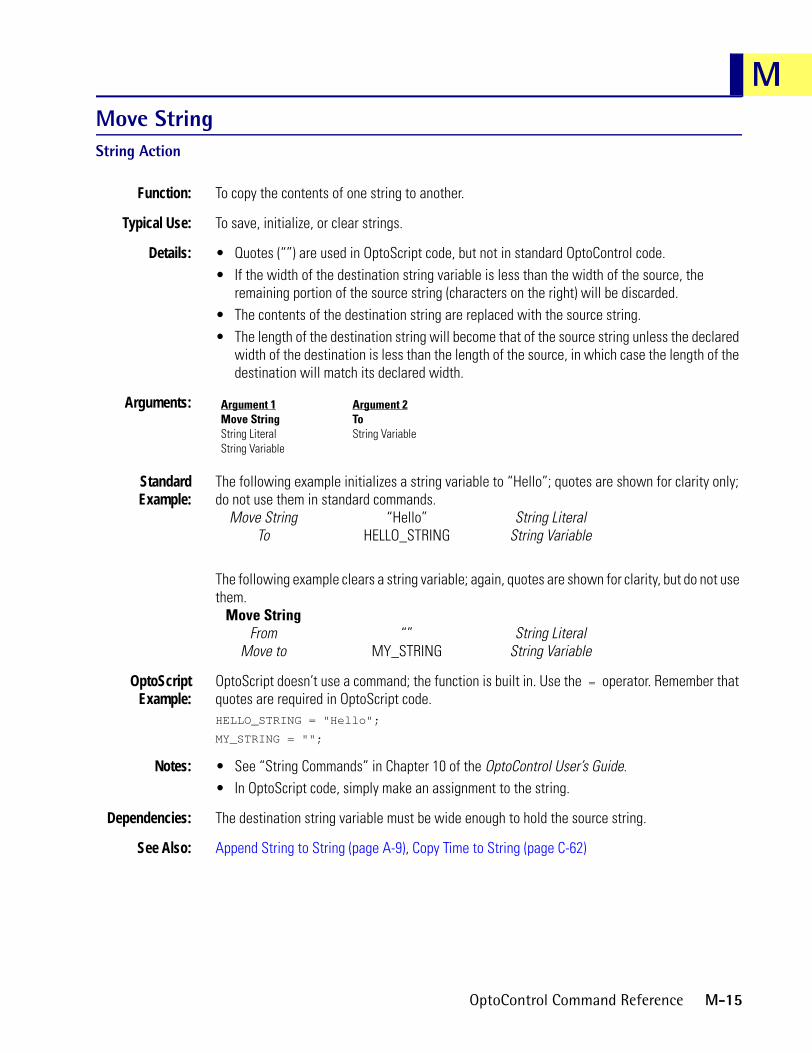
MMove StringString Action
Function: To copy the contents of one string to another.
Typical Use: To save, initialize, or clear strings.
Details: • Quotes (“”) are used in OptoScript code, but not in standard OptoControl code.• If the width of the destination string variable is less than the width of the source, the
remaining portion of the source string (characters on the right) will be discarded.• The contents of the destination string are replaced with the source string.• The length of the destination string will become that of the source string unless the declared
width of the destination is less than the length of the source, in which case the length of the destination will match its declared width.
Arguments:
StandardExample:
The following example initializes a string variable to “Hello”; quotes are shown for clarity only; do not use them in standard commands.
Move String “Hello” String LiteralTo HELLO_STRING String Variable
The following example clears a string variable; again, quotes are shown for clarity, but do not use them.
Move StringFrom “” String Literal
Move to MY_STRING String Variable
OptoScriptExample:
OptoScript doesn’t use a command; the function is built in. Use the = operator. Remember that quotes are required in OptoScript code.HELLO_STRING = "Hello";
MY_STRING = "";
Notes: • See “String Commands” in Chapter 10 of the OptoControl User’s Guide.• In OptoScript code, simply make an assignment to the string.
Dependencies: The destination string variable must be wide enough to hold the source string.
See Also: Append String to String (page A-9), Copy Time to String (page C-62)
Argument 1Move StringString LiteralString Variable
Argument 2ToString Variable
OptoControl Command Reference M-15

Move Table Element to Digital I/O UnitI/O Unit Action
Function: To control multiple digital output points on the same I/O unit simultaneously with a single command.
Typical Use: To efficiently control a selected group of digital outputs with one command.
Details: • This command is 16 times faster than using Turn On or Turn Off 16 times.• Updates the IVALs and XVALs for all 16 points. Affects all output points. Does not affect
input points.• Uses only the lowest (least significant) 16 bits of the table element. Point zero corresponds
to bit 0 (least significant bit) of the table element.• A point is selected for deactivation by setting the respective bit of the table element
to “0.” A point is selected for activation by setting the respective bit of the table element to “1.”
• If a specific point is disabled, only its internal value (IVAL) will be written to. If the entire I/O unit is disabled, only the internal values (IVALS) on all 16 points will be written to.
Arguments:
StandardExample:
Move Table Element to Digital I/O UnitFrom Index 17 Integer 32 Literal
Of Table IO_STATUS_TABLE Integer 32 TableMove to INLET_VALVE_CTRL G4 Digital Multifunction I/O Unit
OptoScriptExample:
MoveTableElementToDigitalIoUnit(From Index, Of Table, Move to)MoveTableElementToDigitalIoUnit(17, IO_STATUS_TABLE, INLET_VALVE_CTRL);
This is a procedure command; it does not return a value.
Notes: In the above example, bit 0 of the element at index 17 of the table will map to point 0 of the I/O unit, bit 1 of the element at index 17 will map to point 1 of the I/O unit, etc.
Queue Errors: 32 = Bad table index value—index was negative or greater than the table size.
See Also: Move Digital I/O Unit to Table Element (page M-9), Set Digital I/O Unit from MOMO Masks (page S-17)
Argument 1From IndexInteger 32 LiteralInteger 32 Variable
Argument 2Of TableInteger 32 Table
Argument 3Move toB100 Digital Multifunction I/O UnitB3000 SNAP DigitalB3000 SNAP Mixed I/OG4 Digital Local Simple I/O UnitG4 Digital Multifunction I/O UnitG4 Digital Remote Simple I/O UnitSNAP Remote Simple Digital
M-16 OptoControl Command Reference

MMove Table Element to TableMiscellaneous Action
Function: To copy a single value from one table to another or from one table element to another table element within the same table.
Typical Use: To reorder the way data are arranged or to copy temporary values to a final location.
Details: • The two tables can be the same table, different types, or the same type.• Any value sent to an invalid index is discarded, and an error 32 is added to the error queue.• The valid range for each index is zero to the table length - 1 (size - 1).
Arguments:
StandardExample:
Move Table Element to TableFrom Index 17 Integer 32 Literal
Of Table I/O_STATUS_TABLE Integer 32 TableTo Index 27 Integer 32 LiteralOf Table I/O_STATUS_TABLE Integer 32 Table
OptoScriptExample:
OptoScript doesn’t use a command; the function is built in. Use the = operator.I/O_STATUS_TABLE[27] = I/O_STATUS_TABLE[17];
Notes: • In OptoScript code, simply make an assignment to the table element. • To move several values, put this command in a loop using variables for both indexes.
Queue Errors: 32 = Bad table index value—index was negative or greater than or equal to the table size.
See Also: Move to Table Element (page M-26)
Move Table to Analog I/O UnitI/O Unit Action
Function: To write values in a float table to all 16 points of an analog I/O unit.
Typical Use: To efficiently write all 16 points of analog data on a single I/O unit with one command.
Details: • This command is four times faster than using Move 16 times.• Updates the IVALs and XVALs for all 16 points except XVALs for input points.• Transfers 16 points of data from the float table beginning at the index specified to the
analog I/O unit. If there are fewer than 16 elements of data from the specified index to the
Argument 1From IndexInteger 32 LiteralInteger 32 Variable
Argument 2Of TableFloat TableInteger 32 TableInteger 64 Table
Argument 3To IndexInteger 32 LiteralInteger 32 Variable
Argument 4Of TableFloat TableInteger 32 TableInteger 64 Table
OptoControl Command Reference M-17

end of the table, no data will be written to the I/O unit and a 32 will be placed in the error queue.
• If a specific point is disabled or if the entire I/O unit is disabled, only the internal values (IVALs) will be written.
• Caution: writes to IVALs of input points.
Arguments:
StandardExample:
Move Table to Analog I/O UnitStart at Index 16 Integer 32 Literal
Of Table DATA_TABLE Float Table (holds 16 values)Move to ANALOG_UNIT_255 G4 Analog Multifunction I/O Unit
OptoScriptExample:
MoveTableToAnalogIoUnit(Start at Index, Of Table, Move to)MoveTableToAnalogIoUnit(16, DATA_TABLE, ANALOG_UNIT_255);
This is a procedure command; it does not return a value.
Notes: If analog I/O units are disabled using Disable Communication to I/O Unit to speed up analog logic execution, perform the following in the order shown:
1. Move Analog I/O Unit to Table (with the I/O unit still disabled)—Copies output IVALs updated by program.
2. Enable Communication to I/O Unit—Re-establishes communications.
3. Move Table to Analog I/O Unit: Writes to the table Moved to above—Updates analog outputs.
4. Move Analog I/O Unit to Table—Updates analog input IVALs.
5. Disable Communication to I/O Unit—Disconnects communications.
6. Program logic . . . (not for use with commands that access MIN, MAX, AVERAGE, etc.)
7. Repeat 1 through 6.
Queue Errors: 32 = Bad table index value—index was negative or greater than the table size.
See Also: Move Analog I/O Unit to Table (page M-7)
Argument 1Start at IndexInteger 32 LiteralInteger 32 Variable
Argument 2Of TableFloat Table
Argument 3Move toB200 Analog Multifunction I/O UnitB3000 SNAP AnalogG4 Analog Multifunction I/O UnitHRD Analog Current Output I/O UnitHRD Analog RTD Input I/O UnitHRD Analog Thermocouple/mV Input I/O UnitHRD Analog Voltage Output I/O UnitHRD Analog Voltage/Current Input I/O Unit
M-18 OptoControl Command Reference

MMove Table to Digital I/O UnitI/O Unit Action
Function: To control multiple digital output points on the same I/O unit simultaneously with a single command.
Typical Use: To efficiently control a selected group of digital outputs with one command.
Details: • This command is 16 times faster than using Turn On or Turn Off 16 times.• Updates the IVALs and XVALs for all 16 points.• Affects all output points. Does not affect input points.• A point is selected for deactivation by setting the respective table element to 0. A point is
selected for activation by setting the respective table element to 1.• Point zero corresponds to the first specified table element.• If a specific point is disabled, only its internal value (IVAL) will be written to. If the entire I/O
unit is disabled, only the internal values (IVALS) on all 16 points will be written to.
Arguments:
StandardExample:
Move Table to Digital I/O UnitStart at Index 17 Integer 32 Literal
Of Table IO_STATUS_TABLE Integer 32 TableMove to INLET_VALVE_CTRL G4 Digital Multifunction I/O Unit
OptoScriptExample:
MoveTableToDigitalIoUnit(Start at Index, Of Table, Move to)MoveTableToDigitalIoUnit(17, IO_STATUS_TABLE, INLET_VALVE_CTRL);
This is a procedure command; it does not return a value.
Notes: In the above example, index 17 of the table will map to point 0 of the I/O unit, index 18 will map to point 1 of the I/O unit, etc.
Queue Errors: 32 = Bad table index value—index was negative or greater than or equal to the table size.
See Also: Set Digital I/O Unit from MOMO Masks (page S-17), Move Digital I/O Unit to Table (page M-8)
Argument 1Start at IndexInteger 32 LiteralInteger 32 Variable
Argument 2Of TableInteger 32 Table
Argument 3Move toB100 Digital Multifunction I/O UnitB3000 SNAP DigitalG4 Digital Local Simple I/O UnitG4 Digital Multifunction I/O UnitG4 Digital Remote Simple I/O UnitSNAP Remote Simple Digital
OptoControl Command Reference M-19

Move Table to Mixed I/O UnitI/O Unit Action
Function: To control multiple analog and digital output points on the same I/O unit simultaneously with a single command.
Typical Use: To efficiently control a selected group of analog and digital outputs with one command.
Details: • This command is much faster than using Turn On, Turn Off, or Move for each point.• Updates the IVALs and XVALs for all 64 points. Affects all output points. Does not affect
input points.• A digital point is turned off by setting the respective table element to 0. A digital point is
turned on by setting the respective table element to non-zero.• An analog point is set by the value in the respective table element.• Point zero corresponds to the first specified table element.• If a specific point is disabled, only its internal value (IVAL) will be written to. If the entire I/O
unit is disabled, only the internal values (IVALS) on all 64 points will be written to.
Arguments:
StandardExample:
Move Table to Mixed I/O UnitStart at Index 4 Integer 32 Variable
Of Table IO_STATUS_TABLE Integer 32 TableMove to VALVE_CONTROL B3000 SNAP Mixed I/O
OptoScriptExample:
MoveTableToMixedIoUnit(Start at Index, Of Table, Move to)MoveTableToMixedIoUnit(4, IO_STATUS_TABLE, VALVE_CONTROL);
This is a procedure command; it does not return a value.
Notes: In the above example, index 4 of the table will map to point 0 of the I/O unit, index 5 will map to point 1 of the I/O unit, and so on.
Queue Errors: 32 = Bad table index value—index was negative or greater than or equal to the table size.
See Also: Move Mixed I/O Unit to Table (page M-13)
Argument 1Start at IndexInteger 32 LiteralInteger 32 Variable
Argument 2Of TableFloat TableInteger 32 Table
Argument 3Move toB3000 SNAP Mixed I/O
M-20 OptoControl Command Reference

MMove Table to Simple-64 I/O UnitI/O Unit Action
Function: To control multiple analog and digital output points on the same SNAP Simple I/O unit simultaneously with a single command.
Typical Use: To efficiently control a selected group of analog and digital outputs with one command.
Details: • This command is much faster than using Turn On, Turn Off, or Move for each point.• Updates the IVALs and XVALs for all 64 points. Affects all output points. Does not affect
input points.• A digital point is turned off by setting the respective table element to 0. A digital point is
turned on by setting the respective table element to non-zero.• An analog point is set by the value in the respective table element.• Point zero corresponds to the first specified table element.• If a specific point is disabled, only its internal value (IVAL) will be written to. If the entire I/O
unit is disabled, only the internal values (IVALS) on all 64 points will be written to.
Arguments:
StandardExample:
Move Table to Simple-64 I/O UnitStart at Index 4 Integer 32 Variable
Of Table IO_STATUS_TABLE Integer 32 TableMove to VALVE_CONTROL SNAP Simple 64
OptoScriptExample:
MoveTableToSimple64IoUnit(Start at Index, Of Table, Move to)MoveTableToSimple64IoUnit(4, IO_STATUS_TABLE, VALVE_CONTROL);
This is a procedure command; it does not return a value.
Notes: In the above example, index 4 of the table will map to point 0 of the I/O unit, index 5 will map to point 1 of the I/O unit, and so on.
Queue Errors: 32 = Bad table index value—index was negative or greater than or equal to the table size.
See Also: Move Simple-64 I/O Unit to Table (page M-14)
Argument 1Start at IndexInteger 32 LiteralInteger 32 Variable
Argument 2Of TableFloat TableInteger 32 Table
Argument 3Move toSNAP Simple 64
OptoControl Command Reference M-21

Move Table to TableMiscellaneous Action
Function: To copy values from one table to another.
Typical Use: To copy temporary values to a final location.
Details: • The two tables must be of the same type and must be different tables. They can be different sizes, but make sure the Length parameter is not too long for either table.
• The valid range for each table index is zero to the table length minus 1 (size - 1).
Arguments:
StandardExample:
Move Table to TableFrom Table Temp_Table Integer 32 TableFrom Index 0 Integer 32 Literal
To Table Status_Table Integer 32 TableTo Index 16 Integer 32 LiteralLength 8 Integer 32 Literal
OptoScriptExample:
MoveTableToTable(From Table, From Index, To Table, To Index, Length)MoveTableToTable(Temp_Table, 0, Status_Table, 16, 8);
This is a procedure command; it does not return a value.
Queue Errors: -6 = Data field error. Source and destination tables must be different.-12 = Invalid table index or length-29 = Wrong object type. Arguments 1 and 3 must both be tables and of the same type.
See Also: Move to Table Element (page M-26)
Argument 1From TableFloat TableInteger 32 TableInteger 64 Table
Argument 2From IndexInteger 32 LiteralInteger 32 Variable
Argument 3To TableFloat TableInteger 32 TableInteger 64 Table
Argument 4To IndexInteger 32 LiteralInteger 32 Variable
Argument 5LengthInteger 32 LiteralInteger 32 Variable
M-22 OptoControl Command Reference

MMove to PointerPointers Action
Function: To assign an object to a pointer.
Typical Use: To initialize a pointer.
Details: The pointer will point to the object specified. Any operation that can be performed on the object can likewise be performed on the pointer. When you perform an operation on a pointer, you are actually performing the operation on the object.
Arguments:
StandardExample:
Move To PointerObject PUMP_VALVE Digital OutputPointer IO_POINTER Pointer Variable
OptoScriptExample:
OptoScript doesn’t use a command; the function is built in. Use the & operator to get the address of the object and use the = operator to make the assignment:IO_POINTER =& PUMP_VALVE;
Notes: • In OptoScript code, simply make an assignment to the pointer. • For standard commands, the Move To Pointer command will be validated when the OK
button in the Add Instruction dialog box is pressed. For OptoScript code, the type will be validated by the compiler.
See Also: Clear Pointer (page C-30), Pointer Equal to NULL? (page P-3)
Argument 1ObjectAnalog Event/ReactionAnalog InputAnalog OutputB100 Digital Multifunction I/O UnitB200 Analog Multifunction I/O UnitB3000 SNAP AnalogB3000 SNAP DigitalB3000 SNAP Mixed I/OChartCounterDigital Event/ReactionDigital InputDigital OutputDown Timer VariableEvent/Reaction GroupFloat TableFloat VariableFrequencyG4 Analog Multifunction I/O UnitG4 Digital Local Simple I/O UnitG4 Digital Multifunction I/O UnitG4 Digital Remote Simple I/O UnitHRD Analog Current Output I/O Unit
HRD Analog RTD Input I/O UnitHRD Analog Thermocouple/mV Input I/O UnitHRD Analog Voltage Output I/O UnitHRD Analog Voltage/Current Input I/O UnitInteger 32 TableInteger 32 VariableInteger 64 TableInteger 64 VariableLocal Simple Digital InputLocal Simple Digital OutputOff PulseOff TotalizerOn PulseOn TotalizerPeriodPID LoopPointer VariableQuadrature CounterSNAP Digital 64SNAP Remote Simple DigitalString TableString VariableTPOUp Timer Variable
Argument 2PointerPointer Variable
OptoControl Command Reference M-23

Move to Pointer TablePointers Action
Function: To assign an object to a pointer table element.
Typical Use: To initialize a pointer table with objects of various types.
Details: • This command takes the pointer for the object being pointed to and moves it to the table element.
• You cannot have pointers pointing to pointers. If you move a pointer to an element of a pointer table, the object being pointed to gets put in the table element.
Arguments:
StandardExample:
Move to Pointer TableObject Valve_One Integer 32 VariableIndex Current_Index Integer 32 Variable
Of Table Digital_Outputs Pointer Table
OptoScriptExample:
OptoScript doesn’t use a command; the function is built in. Use the & operator to get the address of the object and use the = operator to make the assignment:Digital_Outputs[Current_Index] =& Valve_One;
Notes: In OptoScript code, simply make an assignment to the pointer table.
See Also: Move from Pointer Table Element (page M-10), Pointer Table Element Equal to NULL? (page P-4)
Argument 1ObjectAnalog Event/ReactionAnalog InputAnalog OutputB100 Digital Multifunction I/O UnitB200 Analog Multifunction I/O UnitB3000 SNAP AnalogB3000 SNAP DigitalB3000 SNAP Mixed I/OChartCounterDigital Event/ReactionDigital InputDigital OutputDown Timer VariableEvent/Reaction GroupFloat TableFloat VariableFrequencyG4 Analog Multifunction I/O UnitG4 Digital Local Simple I/O UnitG4 Digital Multifunction I/O UnitG4 Digital Remote Simple I/O UnitHRD Analog Current Output I/O UnitHRD Analog RTD Input I/O Unit
HRD Analog Thermocouple/mV Input I/O Unit
HRD Analog Voltage Output I/O UnitHRD Analog Voltage/Current Input I/O Unit
Integer 32 TableInteger 32 VariableInteger 64 TableInteger 64 VariableLocal Simple Digital InputLocal Simple Digital OutputOff PulseOff TotalizerOn PulseOn TotalizerPeriodPID LoopQuadrature CounterSNAP Digital 64SNAP Remote Simple DigitalString TableString VariableTPOUp Timer Variable
Argument 2IndexInteger 32 LiteralInteger 32 Variable
Argument 3Of TablePointer Table
M-24 OptoControl Command Reference

MMove to String TableString Action
Function: To put a string into a string table.
Typical Use: To load strings into a table for later retrieval.
Details: • Quotes (“”) are used in OptoScript code, but not in standard OptoControl code.• Valid range for Index (Argument 2) is zero to the table length - 1 (size - 1).• Strings with a length greater than the width of the table will be truncated to fit.
Arguments:
StandardExample:
In the following example, quotes are shown for clarity only. Do not use them in standard commands.Move to String Table
From “MON” String LiteralTo Index INDEX Integer 32 VariableOf Table STRING_TABLE String Table
OptoScriptExample:
OptoScript doesn’t use a command; the function is built in. Use the = operator. Remember that quotes are required in OptoScript code.STRING_TABLE[INDEX] = "MON";
Notes: • See “String Commands” in Chapter 10 of the OptoControl User’s Guide.• In OptoScript code, simply make an assignment to the table element. • Use to log key events or application errors as if the string table were a “virtual line printer.”
For example, a string table called EVENT_LOG could be used as a circular buffer to store strings containing the time, the date, and a description such as “12-25-96, 1:00:00, Clogged chimney alarm.” An integer variable would also be required to “remember” the next available Index (where the next entry goes).
Queue Errors: 32 = Bad table index value—index was negative or greater than or equal to the table size.
See Also: Move from String Table (page M-11), Get Length of Table (page G-62)
Argument 1FromString LiteralString Variable
Argument 2To IndexInteger 32 LiteralInteger 32 Variable
Argument 3Of TableString Table
OptoControl Command Reference M-25

Move to Table ElementMiscellaneous Action
Function: To copy a value from virtually any source to a table element.
Typical Use: To create a list of various values in a table.
Details: • All numeric type conversions are automatically handled according to the rules detailed for the Move command.
• Any value sent to an invalid index is discarded, and an error 32 is added to the error queue.• The valid range for each index is zero to the table length - 1 (size - 1).
Arguments:
StandardExample:
Move to Table ElementFrom 0 Integer 32 Literal
To Index 27 Integer 32 LiteralOf Table IO_STATUS_TABLE Integer 32 Table
OptoScriptExample:
OptoScript doesn’t use a command; the function is built in. Use the = operator.IO_STATUS_TABLE[27] = 0;
Notes: • In OptoScript code, simply make an assignment to the table element. • To move the same value to several table elements, put this command in a loop using a
variable for the index.
Queue Errors: 32 = Bad table index value—index was negative or greater than or equal to the table size.33 = Overflow—integer or float value was too large.
See Also: Move from Table Element (page M-12)
Argument 1FromAnalog InputAnalog OutputCounterDigital InputDigital OutputFloat LiteralFloat VariableFrequencyInteger 32 LiteralInteger 32 VariableInteger 64 LiteralInteger 64 VariableLocal Simple Digital InputLocal Simple Digital OutputOff PulseOff TotalizerOn PulseOn TotalizerPeriodQuadrature Counter
Argument 2To IndexInteger 32 LiteralInteger 32 Variable
Argument 3Of TableFloat TableInteger 32 TableInteger 64 Table
M-26 OptoControl Command Reference

MMultiplyMathematical Action
Function: To multiply two numeric values.
Typical Use: To multiply two numbers to get a third number or to modify one of the original numbers.
Details: • Multiplies Argument 1 and Argument 2 and places the result in Argument 3.• Argument 3 can be the same as either of the first two arguments (unless they are read-only,
such as analog inputs), or it can be a completely different argument .
Arguments:
StandardExample:
MultiplyIngredient_1_Weight Analog Input
Times Temperature_Adjust Float VariablePut Result in Corrected_Weight Analog Output
OptoScriptExample:
OptoScript doesn’t use a command; the function is built in. Use the * operator.Corrected_Weight = Ingredient_1_Weight * Temperature_Adjust;
Notes: • See “Mathematical Commands” in Chapter 10 of the OptoControl User’s Guide.• In OptoScript code, the * operator can be used in many ways. For more information on
mathematical expressions in OptoScript code, see Chapter 11 of the OptoControl User’s Guide.
• Speed Tip: Use Bit Shift instead for integer math where the multiplier is 2, 4, 8, 16, 32, 64, and so on.
Queue Errors: 33 = Overflow error—result too large.
See Also: Divide (page D-21), Bit Shift (page B-15)
Argument 1[Value]Analog InputAnalog OutputDown Timer VariableFloat LiteralFloat VariableInteger 32 LiteralInteger 32 VariableInteger 64 LiteralInteger 64 VariableUp Timer Variable
Argument 2TimesAnalog InputAnalog OutputDown Timer VariableFloat LiteralFloat VariableInteger 32 LiteralInteger 32 VariableInteger 64 LiteralInteger 64 VariableUp Timer Variable
Argument 3Put Result inAnalog OutputDown Timer VariableFloat VariableInteger 32 VariableInteger 64 VariableUp Timer Variable
OptoControl Command Reference M-27

M-28 OptoControl Command Reference

N
NNatural LogMathematical ActionFunction: To calculate the natural log (base e) of a value.
Typical Use: To solve natural log calculations.
Details: Takes the natural log of Argument 1 and places the result in Argument 2.
Arguments:
StandardExample:
Natural LogOf Fermentation_Rate Float Variable
Put Result in Rate_Calculation Float Variable
OptoScriptExample:
NaturalLog(Of)Rate_Calculation = NaturalLog(Fermentation_Rate);
This is a function command; it returns the natural log of the value. The returned value can be consumed by a variable (as shown) or by another item, such as a mathematical expression or a control structure. See Chapter 11 of the OptoControl User’s Guide for more information.
Notes: OptoControl only implements a natural logarithm command. However, there is a simple way to compute logarithms for bases other than base e. Here’s how to compute a logarithm for base x using only the natural logarithm command:
Just remember that the range of the logarithm argument is a number greater than zero. A controller error will be flagged if the argument is less than or equal to zero.To get a log10, divide the result of this command by 2.302585, which is ln(10).
NUMBER LOGe LOG101 0 010 2.302585 1100 4.605170 2
1000 6.907755 3
Argument 1OfAnalog InputAnalog OutputDown Timer VariableFloat LiteralFloat VariableInteger 32 LiteralInteger 32 VariableUp Timer Variable
Argument 2Put Result inAnalog OutputDown Timer VariableFloat VariableInteger 32 VariableUp Timer Variable
Logbase(number) = ln(number)ln(base)
For example: Log10(100) = ln(100) = 2 ln(10)
OptoControl Command Reference N-1

Queue Errors: 33 = Overflow error—result too large.35 = Not a number—result invalid.
See Also: Raise to Power (page R-2)
NOTLogical Action
Function: To perform a logical NOT (True/False toggle) on any allowable value.
Typical Uses: • To invert the logical state of an integer variable.• To toggle the state of a digital output.• To have a digital output assume the inverse state of a digital input.
Details: • Performs a logical NOT on Argument 1 and puts result in Argument 2. Examples:Argument 1 Argument 2
0 -1-1 022 0
• Performs this action on a copy of Argument 1, then moves the copy to Argument 2.• If Argument 1 is True (non-zero), the result will be False (0). If Argument 1 is False (0), the
result will be True (-1).
Arguments:
StandardExample:
NOTCurrent_State Integer 32 Variable
Put Result in DOUT1 Digital Output
OptoScriptExample:
OptoScript doesn’t use a command; the function is built in. Use the not operator. DOUT1 = not Current_State;
Notes: • See “Logical Commands” in Chapter 10 of the OptoControl User’s Guide. The example shown is only one of many ways to use the not operator. For more information on logical operators in OptoScript code, see Chapter 11 of the OptoControl User’s Guide.
• It is advisable to use only integers or digital channels with this command.• To invert the True/False state of Argument 1, make both arguments the same.
Argument 1[Value]Digital InputDigital OutputFloat LiteralFloat VariableInteger 32 LiteralInteger 32 VariableInteger 64 LiteralInteger 64 VariableLocal Simple Digital InputLocal Simple Digital Output
Argument 2Put Result inDigital OutputFloat VariableInteger 32 VariableInteger 64 VariableLocal Simple Digital Output
N-2 OptoControl Command Reference

N• To toggle all 32 bits, use Bit NOT.
See Also: Bit NOT (page B-5)
NOT?Logical Condition
Function: To determine if a value is False (zero, off).
Typical Use: To perform False testing.
Details: • Determines if Argument 1 is False. Examples:Argument 1 Result
0 True-1 False22 False
• Evaluates True if Argument 1 is False (zero, off). Evaluates False if Argument 1 is True (non-zero, on).
• Functionally equivalent to Variable False?
Arguments:
StandardExample:
Is CURRENT_STATE Integer 32 VariableNOT?
OptoScriptExample:
OptoScript doesn’t use a command; the function is built in. Use the not operator. if (not Current_State) then
Notes: • See “Logical Commands” in Chapter 10 of the OptoControl User’s Guide. The example shown is only one of many ways to use the not operator. For more information on logical operators in OptoScript code, see Chapter 11 of the OptoControl User’s Guide.
• It is advisable to use only integers or digital channels with this command.• To determine whether a value is True (non-zero), use either Variable True? or the False exit.
See Also: AND? (page A-7), OR? (page O-8), XOR? (page X-3), Variable True? (page V-2)
Argument 1IsDigital InputDigital OutputFloat LiteralFloat VariableInteger 32 LiteralInteger 32 VariableInteger 64 LiteralInteger 64 VariableLocal Simple Digital InputLocal Simple Digital Output
OptoControl Command Reference N-3

Not Equal?Logical Condition
Function: To determine if two values are different.
Typical Use: To perform reverse logic.
Details: • Determines if Argument 1 is different from Argument 2. Evaluates True if the two values are different, False otherwise. Examples:
Argument 1 Argument 2 Result0 0 False-1 0 True
255 65280 True22.22 22.22 False
Arguments:
StandardExample:
Is BATCH_STEP Integer 32 VariableNot Equal?
To 4 Integer 32 Literal
OptoScriptExample:
OptoScript doesn’t use a command; the function is built in. Use the <> operator.if (BATCH_STEP <> 4) then
Notes: • See “Logical Commands” in Chapter 10 of the OptoControl User’s Guide. In OptoScript code, the <> operator can be used in several ways. For more information on comparison operators in OptoScript code, see Chapter 11 of the OptoControl User’s Guide.
• Use Within Limits? to test for an approximate match. To test for equality, use either Equal? or the False exit.
Argument 1IsAnalog InputAnalog OutputCounterDigital InputDigital OutputDown Timer VariableFloat LiteralFloat VariableFrequencyInteger 32 LiteralInteger 32 VariableInteger 64 LiteralInteger 64 VariableLocal Simple Digital InputLocal Simple Digital OutputOff PulseOff TotalizerOn PulseOn TotalizerPeriodQuadrature CounterUp Timer Variable
Argument 2ToAnalog InputAnalog OutputCounterDigital InputDigital OutputDown Timer VariableFloat LiteralFloat VariableFrequencyInteger 32 LiteralInteger 32 VariableInteger 64 LiteralInteger 64 VariableLocal Simple Digital InputLocal Simple Digital OutputOff PulseOff TotalizerOn PulseOn TotalizerPeriodQuadrature CounterUp Timer Variable
N-4 OptoControl Command Reference

NSee Also: Greater? (page G-106), Less? (page L-1), Less Than or Equal? (page L-2),
Greater Than or Equal? (page G-107), Equal? (page E-16), Within Limits? (page W-1)
Not Equal to Table Element?Logical Condition
Function: To determine if a numeric value is different from a specified value in a float or integer table.
Typical Use: To perform reverse logic.
Details: • Determines if one value (Argument 1) is different from another (a value at index Argument 2 in float or integer table Argument 3). Examples:
Value 1 Value 2 Result0.0 0.0 False
0.0001 0.0 True-98.765 -98.765 False-32768 -32768 False2222 2222 False
• Evaluates True if the two values are different, False otherwise.
Arguments:
StandardExample:
Is This_Reading Float VariableNot Equal to Table Element?
At Index Table_Index Integer 32 VariableOf Table Table_of_Readings Float Table
OptoScriptExample:
OptoScript doesn’t use a command; the function is built in. Use the <> operator.if (This_Reading <> Table_of_Readings[Table_Index]) then
Argument 1IsAnalog InputAnalog OutputCounterDigital InputDigital OutputDown Timer VariableFloat LiteralFloat VariableFrequencyInteger 32 LiteralInteger 32 VariableInteger 64 LiteralInteger 64 VariableLocal Simple Digital InputLocal Simple Digital OutputOff PulseOff TotalizerOn PulseOn TotalizerPeriodQuadrature CounterUp Timer Variable
Argument 2At IndexInteger 32 LiteralInteger 32 Variable
Argument 3Of TableFloat TableInteger 32 TableInteger 64 Table
OptoControl Command Reference N-5

Notes: • See “Logical Commands” in Chapter 10 of the OptoControl User’s Guide. • In OptoScript code, the <> operator can be used in several ways. For more information on
comparison operators in OptoScript code, see Chapter 11 of the OptoControl User’s Guide.• To test for equality, use either Equal to Table Element? or the False exit.
Queue Errors: 32 = Bad table index value—index was negative or greater than or equal to table size.
See Also: Greater Than Table Element? (page G-109), Less Than Table Element? (page L-5), Less Than or Equal to Table Element? (page L-3), Greater Than or Equal to Table Element? (page G-108), Equal to Table Element? (page E-18)
N-6 OptoControl Command Reference

O
OOff?Digital Point ConditionFunction: To determine if a digital input or output is off.
Typical Use: To determine the status of a digital input or output point.
Details: • Evaluates True if the specified point is off, False if the point is on.• Speed Tip: Use Get Digital I/O Unit as Binary Value to get the state of all 16 points at once.
Then use Bit Test to determine the state of individual points.
Arguments:
StandardExample:
Is Safety_Interlock Local Simple Digital InputOff?
OptoScriptExample:
IsOff(Point)if (IsOff(Safety_Interlock)) then
This is a function command; it returns a value of true (non-zero) or false (0). The returned value can be consumed by a control structure (as in the example shown) or by a variable, I/O point, etc. See Chapter 11 of the OptoControl User’s Guide for more information.
Notes: May be used with either input or output points.
Dependencies: Applies to all inputs and outputs on digital multifunction I/O units and local simple I/O units.
See Also: On? (page O-3)
Argument 1IsDigital InputDigital OutputLocal Simple Digital InputLocal Simple Digital Output
OptoControl Command Reference O-1

Off-Latch Set?Digital Point Condition
Function: Checks the status of the specified Off Latch.
Typical Use: To determine if a button was pressed or an object passed by a sensor.
Details: Evaluates True if the latch is set, which indicates that the specified input changed from On to Off.
Arguments:
StandardExample:
On Point PUMP3_STOP_BUTTONOff-Latch Set?
OptoScriptExample:
IsOffLatchSet(On Point)if (IsOffLatchSet(PUMP3_STOP_BUTTON)) then
This is a function command; it returns a value of true (non-zero) or false (0). The returned value can be consumed by a control structure (as in the example shown) or by a variable, I/O point, etc. See Chapter 11 of the OptoControl User’s Guide for more information.
Notes: Use Clear Off-Latch if True to reset the latch for next time.
See Also: On-Latch Set? (page O-4)
Argument 1On PointDigital Input
O-2 OptoControl Command Reference

OOn?Digital Point Condition
Function: To determine if a digital input or output is on.
Typical Use: To determine the status of a digital input or output point.
Details: Evaluates True if the specified point is on, False if the point is off.
Arguments:
StandardExample:
Is Motor_Power Local Simple Digital InputOn?
OptoScriptExample:
IsOn(Point)if (IsOn(Motor_Power)) then
This is a function command; it returns a value of true (non-zero) or false (0). The returned value can be consumed by a control structure (as in the example shown) or by a variable, I/O point, etc. See Chapter 11 of the OptoControl User’s Guide for more information.
Notes: • May be used with either input or output points.• Speed Tip: Use Get Digital I/O Unit as Binary Value to get the state of all 16 points at once.
Then use Bit Test to determine the state of individual points.
Dependencies: Applies to all inputs and outputs on digital multifunction I/O units and local simple I/O units.
See Also: Off? (page O-1)
Argument 1IsDigital InputDigital OutputLocal Simple Digital InputLocal Simple Digital Output
OptoControl Command Reference O-3
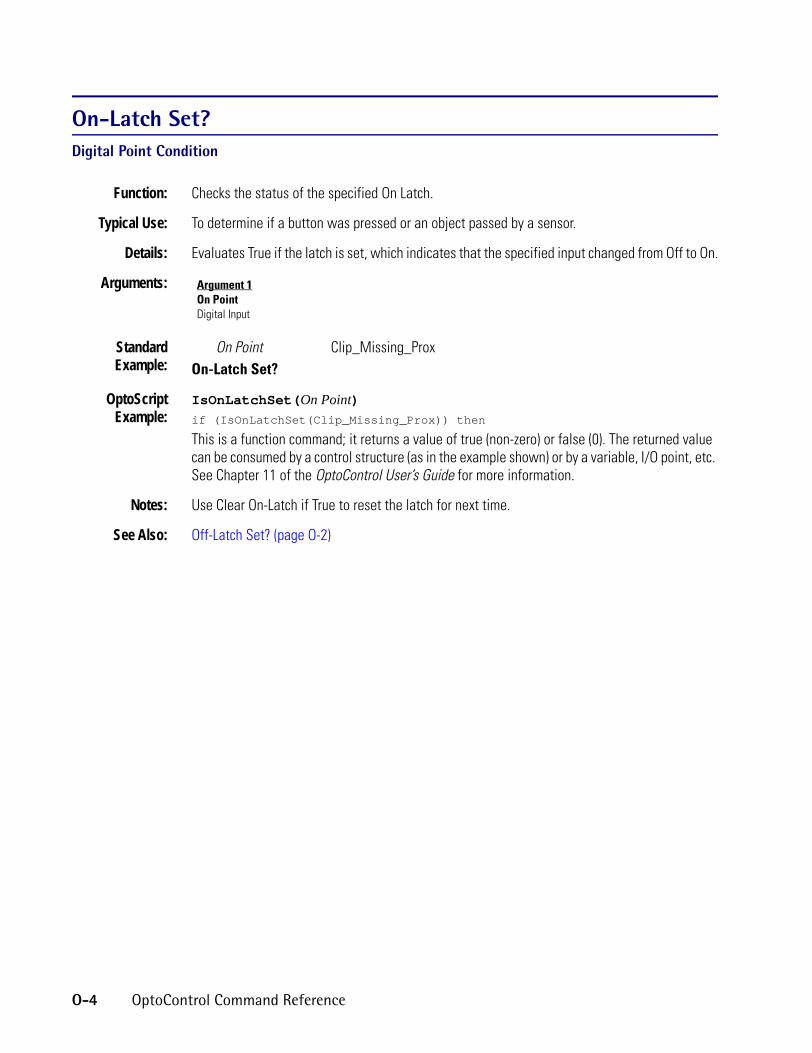
On-Latch Set?Digital Point Condition
Function: Checks the status of the specified On Latch.
Typical Use: To determine if a button was pressed or an object passed by a sensor.
Details: Evaluates True if the latch is set, which indicates that the specified input changed from Off to On.
Arguments:
StandardExample:
On Point Clip_Missing_ProxOn-Latch Set?
OptoScriptExample:
IsOnLatchSet(On Point)if (IsOnLatchSet(Clip_Missing_Prox)) then
This is a function command; it returns a value of true (non-zero) or false (0). The returned value can be consumed by a control structure (as in the example shown) or by a variable, I/O point, etc. See Chapter 11 of the OptoControl User’s Guide for more information.
Notes: Use Clear On-Latch if True to reset the latch for next time.
See Also: Off-Latch Set? (page O-2)
Argument 1On PointDigital Input
O-4 OptoControl Command Reference

OOpen Ethernet SessionCommunication—Network Action
Function: To establish a dedicated link with another Ethernet node.
Typical Use: To communicate to other devices via Ethernet or to establish peer-to-peer communication between two or more controllers using Ethernet.
Details: • The full address (also called session name) of the other node must be known. Aliases can be used if supported by the network.
• You must prefix the address with [T:].• Valid ports are 8, 9, and 10. If the host port is Ethernet, do not use port 8 for peer-to-peer
communication, since it is the host port.
Arguments:
StandardExample:
Open Ethernet SessionSession Name MIS_LINK String Literal
On Port 9 Integer 32 LiteralPut Result in PEER3_SESSION_NUMBER Integer 32 Variable
OptoScriptExample:
OpenEthernetSession(Session Name, On Port)PEER3_SESSION_NUMBER = OpenEthernetSession(MIS_LINK, 9);
This is a function command; it returns either the session number (0–127) or a status code as defined below.
Notes: • An Ethernet session is a logical link (a virtual dedicated cable) between two nodes. Up to 32 sessions total can be concurrently established on the three logical Ethernet ports 8, 9, and 10 to talk peer-to-peer or host. These three ports use the same Ethernet card.Controller Port # Typical Use TCP/IP Port #
8 Host Port 20019 Peer Port 2002
10 Peer Port 2003
• The remaining sessions (up to a total of 128) are used for I/O units. Up to 100 Ethernet I/O unit sessions are supported per controller.
• Upon success, a session number of 0-127 is returned as a local alias for the session name. The session number is used thereafter. Assigning the number may take as long as 15 seconds for a local node, much longer for a distant node. A negative value indicates failure (see Status Codes, below).
• Initialize the result variable with a negative number to avoid confusion with a successful returned value (zero is a valid session number).
• When connecting over a busy network or through switches, make sure the session is open by adding a delay (for example, 10 milliseconds) to the chart and checking the status of the session using Get Number of Characters Waiting on Ethernet Session. The amount of delay
Argument 1Session NameString LiteralString Variable
Argument 2On PortInteger 32 LiteralInteger 32 Variable
Argument 3Put Result inInteger 32 Variable
OptoControl Command Reference O-5

needed depends on your network. See additional suggestions in the section on Ethernet peer-to-peer communication in the OptoControl User’s Guide, Chapter 10.
• It can take up to two minutes for the controller’s Ethernet adapter card to finish built-in TCP/IP communication retries, depending on how retries are set for the card. (See Opto 22 form 1156, the M4SENET-100 Installation Guide, for more information.) If you use Open Ethernet Session again too soon, the resulting multiple attempts to open the session can completely clog the queue. In your strategy, put in a delay between attempts to open an Ethernet session.
• To open a session with a specific port of another device (for example, to establish peer-to-peer communications with the Ethernet peer port of another Opto 22 controller), the port number must be appended to the session name string. For example, if the TCP/IP address is 10.192.53.85 and the peer port is 2002, then the session name string would be T:10.192.53.85:2002.
• To find out a session number when another controller has initiated the link, use the command Accept Session on TCP Port.
Result Data: 0-127 = Session number, which is assigned as a local alias for the session name.
Status Codes: -40 = Timeout—specified port already in use.-51 = Invalid port number—use 8, 9, or 10.-70 = No Ethernet card present.-71 = All 32 sessions are in use.-72 = Timeout—Couldn’t open the session.-77 = This controller doesn’t support Ethernet. -79 = Open request has timed out. Make sure IP address is correct and cables are connected.
See Also: Close Ethernet Session (page C-34), Accept Session on TCP Port (page A-2)
ORLogical Action
Function: To perform a logical OR on any two allowable values.
Typical Use: To use the True state of either value to control an output or set an alarm.
Details: • Performs a logical OR on Argument 1 and Argument 2 and puts result in Argument 3. The result is -1 (True) if either value is non-zero, 0 (False) otherwise.Examples:
Argument 1 Argument 2 Argument30 0 0-1 0 -10 -1 -1-1 -1 -1
• The result can be sent directly to a digital output if desired.
O-6 OptoControl Command Reference

OArguments:
StandardExample:
ORLIMIT_SWITCH1 Local Simple Digital Input
With LIMIT_SWITCH2 Local Simple Digital OutputPut Result in MOTOR1_OUTPUT Digital Output
OptoScriptExample:
OptoScript doesn’t use a command; the function is built in. Use the or operator. MOTOR1_OUTPUT = LIMIT_SWITCH1 or LIMIT_SWITCH2;
Notes: • See “Logical Commands” in Chapter 10 of the OptoControl User’s Guide. The example shown is only one of many ways to use the or operator. For more information on logical operators in OptoScript code, see Chapter 11 of the OptoControl User’s Guide.
• It is advisable to use only integers or digital points with this command.• In OptoScript code, you can combine logical operators and OR multiple variables, for
example: x = a or b or c or d; • In standard OptoControl code, to OR multiple variables (such as A, B, C, and D) into one
variable (such as RESULT), do the following:
1. OR A with B, Move To RESULT.
2. OR C with RESULT, Move To RESULT.
3. OR D with RESULT, Move To RESULT.• To test or manipulate individual bits, use Bit OR.
See Also: Bit OR (page B-10)
Argument 1[Value]Digital InputDigital OutputFloat LiteralFloat VariableInteger 32 LiteralInteger 32 VariableInteger 64 LiteralInteger 64 VariableLocal Simple Digital InputLocal Simple Digital Output
Argument 2WithDigital InputDigital OutputFloat LiteralFloat VariableInteger 32 LiteralInteger 32 VariableInteger 64 LiteralInteger 64 VariableLocal Simple Digital InputLocal Simple Digital Output
Argument 3Put Result inDigital OutputFloat VariableInteger 32 VariableInteger 64 VariableLocal Simple Digital Output
OptoControl Command Reference O-7

OR?Logical Condition
Function: To determine if either or both of two values are True.
Typical Use: To OR? two values within an AND? type condition block.
Details: • Determines if Argument 1 or Argument 2 is non-zero. Examples:Argument 1 Argument 2 Result
0 0 False-1 0 True0 -1 True-1 -1 True
• Evaluates True if either argument is True (non-zero, on). Evaluates False if both arguments are False (zero, off).
Arguments:
StandardExample:
Is LIMIT_SWITCH1 Local Simple Digital InputOR?
LIMIT_SWITCH2 Digital Input
OptoScriptExample:
OptoScript doesn’t use a command; the function is built in. Use the or operator. if (LIMIT_SWITCH1 or LIMIT_SWITCH2) then
Notes: • See “Logical Commands” in Chapter 10 of the OptoControl User’s Guide. The example shown is only one of many ways to use the or operator. For more information on logical operators in OptoScript code, see Chapter 11 of the OptoControl User’s Guide.
• It is advisable to use only integers or digital points with this command.• To determine whether both values are False (zero, off), use either Variable False? or the
False exit.• Multiple uses of OR? within a condition block result in the OR? pairs being AND?ed.
See Also: NOT (page N-2), AND? (page A-7) XOR? (page X-3)
Argument 1IsDigital InputDigital OutputFloat LiteralFloat VariableInteger 32 LiteralInteger 32 VariableInteger 64 LiteralInteger 64 VariableLocal Simple Digital InputLocal Simple Digital Output
Argument 2[Value]Digital InputDigital OutputFloat LiteralFloat VariableInteger 32 LiteralInteger 32 VariableInteger 64 LiteralInteger 64 VariableLocal Simple Digital InputLocal Simple Digital Output
O-8 OptoControl Command Reference

P
PPause TimerMiscellaneous ActionFunction: To pause a timer variable.
Typical Use: Used with the Continue Timer command to trade on or off time of a variable or I/O point.
Details: • The timer must have been started with either the Start Timer or Move commands.• To continue a paused timer from the value it was paused at, use the command Continue
Timer.
Arguments:
StandardExample:
Pause TimerTimer OVEN_TIMER Down Timer Variable
OptoScriptExample:
PauseTimer(Timer)PauseTimer(OVEN_TIMER);
This is a procedure command; it does not return a value.
Notes: See “Miscellaneous Commands” in Chapter 10 of the OptoControl User’s Guide for more information on using timers.
See Also: Start Timer (page S-62), Stop Timer (page S-68), Continue Timer (page C-45), Set Down Timer Preset Value (page S-19), Set Up Timer Target Value (page S-46)
Argument 1TimerDown Timer VariableUp Timer Variable
OptoControl Command Reference P-1

PID Loop Communication Enabled?Simulation Condition
Function: Checks a flag internal to the controller to determine if communication to the specified PID loop is enabled.
Typical Use: Primarily used in factory QA testing and simulation.
Details: Evaluates True if communication is enabled.
Arguments:
StandardExample:
PID Loop FACTORY_HEAT_2BAPID Loop Communication Enabled?
OptoScriptExample:
IsPidLoopCommEnabled(PID Loop)if (IsPidLoopCommEnabled(FACTORY_HEAT_2BA)) then
This is a function command; it returns a value of true (non-zero) or false (0). The returned value can be consumed by a control structure (as in the example shown) or by a variable, I/O point, etc. See Chapter 11 of the OptoControl User’s Guide for more information.
See Also: I/O Point Communication Enabled? (page I-7)
Argument 1PID LoopPID Loop
P-2 OptoControl Command Reference

PPointer Equal to NULL?Pointers Condition
Function: To determine if a pointer is pointing to an object.
Typical Use: To verify that a pointer is pointing to an object (to prevent an undefined pointer).
Details: Evaluates False if the pointer is pointing to an object, True otherwise.
Arguments:
StandardExample:
Pointer IO_Pointer Pointer VariablePointer Equal to NULL?
OptoScriptExample:
OptoScript doesn’t use a command; the function is built in. Use the == and null operators.if (IO_Pointer == null) then
Notes: • The example shown is only one way to use these operators. For more information on operators in OptoScript code, see Chapter 11 of the OptoControl User’s Guide.
• If you try to perform an operation on a NULL pointer, an error 61 will be posted in the error queue.
See Also: Clear Pointer (page C-30), Move to Pointer (page M-23)
Argument 1PointerPointer Variable
OptoControl Command Reference P-3

Pointer Table Element Equal to NULL?Pointers Condition
Function: To determine if a specific element of a pointer table contains an object.
Typical Use: To verify that an element in a pointer table is pointing to an object (to prevent an undefined pointer).
Details: Evaluates False if the specified element is pointing to an object, True otherwise.
Arguments:
StandardExample:
Index Current_Index Integer 32 VariablePointer Table Element Equal to NULL?
Of Table IO_Table Pointer Table
OptoScriptExample:
OptoScript doesn’t use a command; the function is built in. Use the == and null operators.if (IO_Table[Current_Index] == null) then
Notes: • The example shown is only one way to use these operators. For more information on operators in OptoScript code, see Chapter 11 of the OptoControl User’s Guide.
• If you try to perform an operation on a NULL pointer, an error 61 will be posted in the error queue.
See Also: Clear Pointer Table Element (page C-31), Move to Pointer Table (page M-24)
Argument 1IndexInteger 32 LiteralInteger 32 Variable
Argument 2Of TablePointer Table
P-4 OptoControl Command Reference

R
RRaise e to PowerMathematical ActionFunction: To raise the constant e to a specified power.
Typical Use: To solve mathematical equations where the constant e is required.
Details: • Raises e to the power specified in Argument 1.• The constant e, the base of the natural system of logarithms, has a value of 2.7182818.• The power (Argument 1) must be between -88.33654 and 88.72283.
Arguments:
StandardExample:
Raise e to PowerExponent Gas_Pressure Analog Input
Put Result in Pressure_Calculation Float Variable
OptoScriptExample:
RaiseEToPower(Exponent)Pressure_Calculation = RaiseEToPower(Gas_Pressure);
This is a function command; it returns the result of the mathematical computation. The returned value can be consumed by a variable (as shown) or by another item, such as a math expression or a control structure. See Chapter 11 of the OptoControl User’s Guide for more information.
Notes: See “Mathematical Commands” in Chapter 10 of the OptoControl User’s Guide.
Queue Errors: 33 = Overflow error—result too large.
See Also: Natural Log (page N-1), Raise to Power (page R-2)
Argument 1ExponentAnalog InputAnalog OutputDown Timer VariableFloat LiteralFloat VariableInteger 32 LiteralInteger 32 VariableUp Timer Variable
Argument 2Put Result inAnalog OutputDown Timer VariableFloat VariableInteger 32 VariableUp Timer Variable
OptoControl Command Reference R-1

Raise to PowerMathematical Action
Function: To raise a value to a specified power.
Typical Use: To solve exponentiation calculations.
Details: • Raises Argument 1 to the power specified by Argument 2 and places the result in Argument 3.
• For use with positive numbers only.
Arguments:
StandardExample:
Raise to PowerRaise 10 Integer 32 LiteralTo the 2 Integer 32 Literal
Put Result in TEN_SQUARED Integer 32 Variable
OptoScriptExample:
Power(Raise, To the)TEN_SQUARED = Power(10, 2);
This is a function command; it returns the result of the mathematical computation. The returned value can be consumed by a variable (as shown) or by another item, such as a math expression or a control structure. See Chapter 11 of the OptoControl User’s Guide for more information.
Notes: • See “Mathematical Commands” in Chapter 10 of the OptoControl User’s Guide.• Multiplying a number by itself is faster than raising a number to the power of 2.
Queue Errors: 33 = Overflow error—result too large.35 = Not a number—result invalid.
See Also: Raise e to Power (page R-1), Square Root (page S-52)
Argument 1RaiseAnalog InputAnalog OutputDown Timer VariableFloat LiteralFloat VariableInteger 32 LiteralInteger 32 VariableUp Timer Variable
Argument 2To theAnalog InputAnalog OutputDown Timer VariableFloat LiteralFloat VariableInteger 32 LiteralInteger 32 VariableUp Timer Variable
Argument 3Put Result inAnalog OutputDown Timer VariableFloat VariableInteger 32 VariableUp Timer Variable
R-2 OptoControl Command Reference

RRamp Analog OutputAnalog Point Action
Function: To change an analog output value to a new value at a constant rate.
Typical Use: To raise or lower oven temperature from point A to point B at a specified rate.
Details: • When the I/O unit receives this command, it will assume control of the analog output channel.
• Ramping starts from the current output value and proceeds toward the specified endpoint value.
• The ramp rate is specified in engineering units per second. A rate of zero is illegal (returns a queue error 7).
• Updates to the current output value will be made at 50-millisecond intervals.• If this command is executed while the output is ramping, the ramp rate will be changed. If
this command is executed too frequently, the output will not get a chance to ramp at all.• Not available on SNAP Ethernet brains.
Arguments:
StandardExample:
Ramp Analog OutputRamp Endpoint SOAK_TEMP Float Variable
Units/Sec RAMP_RATE Float VariablePoint to Ramp TEMP_CONTROL Analog Output
OptoScriptExample:
RampAnalogOutput(Ramp Endpoint, Units/Sec, Point to Ramp)RampAnalogOutput(SOAK_TEMP, RAMP_RATE, TEMP_CONTROL);
This is a procedure command; it does not return a value.
Notes: • To stop the ramp at any time, use Move (or an assignment in OptoScript code) to send the desired “static” value to the analog output channel.
• Use this command only to change or start the ramp.• Be sure the analog output value is at the desired starting point before using this command.• If the output value must be changed, wait at least 50 milliseconds before using this
command.
Queue Errors: 7 = Value sent to I/O unit is out of range.
Argument 1Ramp EndpointFloat LiteralFloat VariableInteger 32 LiteralInteger 32 Variable
Argument 2Units/SecFloat LiteralFloat VariableInteger 32 LiteralInteger 32 Variable
Argument 3Point to RampAnalog Output
OptoControl Command Reference R-3

Read Byte from PC Memory (ISA only)Controller Action
Function: Read one byte from memory on another card in the PC.
Typical Use: To get eight-bit data from other cards plugged into the PC bus via the assigned memory address for the card.
Details: • When the ISA controller is used in a typical PC, this command must first get permission from the DMA controller in the PC to talk over the bus. This is a relatively slow process.
• When the ISA controller is used in a passive backplane as the bus master, this command executes immediately.
• The value read is treated as an unsigned short.
Arguments:
StandardExample:
Read Byte from PC Memory (ISA only)From Address 851968 Integer 32 Literal
Put in Byte_Read Integer 32 Variable
OptoScriptExample:
ReadByteFromPcMemory(From Address)Byte_Read = ReadByteFromPcMemory(851968);
This is a function command; it returns the byte read from the other card. The returned value can be consumed by a variable (as shown) or by another item, such as a math expression or a control structure. See Chapter 11 of the OptoControl User’s Guide for more information.
Notes: • Utilities Set DMA0, Set DMA5, Set DMA6, and Set DMA7 can be used to set up DMA channels.
• Memory on the PC motherboard cannot be accessed.• A -1 is returned if the DMA channel in the PC has not been configured.• A value of 255 is returned when there is no card present at the address specified.
Dependencies: When the ISA controller is used in a typical PC, one of the unused DMA channels in the PC must be configured for use by the ISA controller. Likewise, the ISA controller must be configured to use the chosen DMA channel. See the ISA controller manual for details.
See Also: Read Word from PC Memory (ISA only) (page R-12), Read Byte from PC Port (ISA only) (page R-5)
Argument 1From AddressInteger 32 LiteralInteger 32 Variable
Argument 2Put inInteger 32 Variable
R-4 OptoControl Command Reference

RRead Byte from PC Port (ISA only)Controller Action
Function: Read one byte from a port in the PC.
Typical Use: To get eight-bit data from other cards plugged into the PC bus via the assigned port address for the card.
Details: • When the ISA controller is used in a typical PC, this command must first get permission from the DMA controller in the PC to talk over the bus. This is a relatively slow process.
• When the ISA controller is used in a passive backplane as the bus master, this command executes immediately.
• The value read is treated as an unsigned short.
Arguments:
StandardExample:
Read Byte from PC Port (ISA only)From Address 744 Integer 32 Literal
Put in BYTE_READ Integer 32 Variable
OptoScriptExample:
ReadByteFromPcPort(From Address)BYTE_READ = ReadByteFromPcPort(744);
This is a function command; it returns the byte read from the PC port. The returned value can be consumed by a variable (as shown) or by another item, such as a math expression or a control structure. See Chapter 11 of the OptoControl User’s Guide for more information.
Notes: • Utilities Set DMA0, Set DMA5, Set DMA6, and Set DMA7 can be used to set up DMA channels.
• PC port addresses range from 000 to 3FF hex.• A -1 is returned if the DMA channel in the PC has not been configured and must be entered
in decimal.• A value of 255 is returned when there is no card present at the port address specified.
Dependencies: When the ISA controller is used in a typical PC, one of the unused DMA channels in the PC must be configured for use by the ISA controller. Likewise, the ISA controller must be configured to use the chosen DMA channel. See the ISA controller manual for details.
See Also: Read Word from PC Port (ISA only) (page R-13), Read Byte from PC Memory (ISA only) (page R-4)
Argument 1From AddressInteger 32 LiteralInteger 32 Variable
Argument 2Put inInteger 32 Variable
OptoControl Command Reference R-5

Read Event/Reaction Hold BufferEvent/Reaction Action
Function: To get a value that was stored at the I/O unit as a reaction to a specific event.
Typical Use: To capture a counter value at the moment a digital input turned on (or off).
Details: • There are 256 32-bit holding buffers, one for each event/reaction. If a channel is configured as a counter and the reaction is to send its value to the hold buffer, the counts will be in the hold buffer for the specified event/reaction.
• Other values, such as period measurements and analog inputs, may also be captured.
Arguments:
StandardExample:
Read Event/Reaction Hold BufferEvent/Reaction Sequence_Finished Analog Event/Reaction
Put in Counter_Value Integer 32 Variable
OptoScriptExample:
ReadEventReactionHoldBuffer(Event/Reaction)Counter_Value = ReadEventReactionHoldBuffer(Sequence_Finished);
This is a function command; it returns the value in the event/reaction hold buffer. The returned value can be consumed by a variable (as shown) or by another item, such as a math expression or a control structure. See Chapter 11 of the OptoControl User’s Guide for more information.
Notes: • See “Event/Reaction Commands” in Chapter 10 of the OptoControl User’s Guide.• Use Event Occurred? to determine if there is a value to be read.
Dependencies: • Event/reactions must be named and configured on the I/O unit before they can be referenced.
• Event/reactions are not supported on local simple I/O units.
Read Numeric Table from I/O Memory MapCommunication—I/O Action
Function: Read a range of values from an Opto 22 SNAP Ethernet I/O memory map and store them into an integer 32 or float table.
Typical Use: To access areas of the memory map not directly supported by OptoControl.
Details: • This command works with SNAP Ethernet I/O units that have been configured in OptoControl. The controller must be connected to the I/O unit for this command to work.
Argument 1Event/ReactionAnalog Event/ReactionDigital Event/Reaction
Argument 2Put inFloat VariableInteger 32 Variable
R-6 OptoControl Command Reference

R• Argument 1, Length, is the length of data in the memory map in quads (groups of four
bytes) and also the number of table elements. Maximum length is 64 quadlets (256 bytes).• Argument 4, Mem address, includes only the last eight digits of the memory map address
(the lower 32 bits).
Arguments:
StandardExample:
Read Numeric Table from I/O Memory MapLength 0x10 Integer 32 Literal
Start Index 0x5 Integer 32 LiteralI/O Unit MYIOUNIT B3000 SNAP Mixed I/O
Mem address 0xFFFFFFFF Integer 32 LiteralTo MYINTTABLE Integer 32 Table
Put Status in STATUS Integer 32 Variable
OptoScriptExample:
ReadNumTableFromIoMemMap(Length, Start Index, I/O Unit, Mem address, To)STATUS = ReadNumTableFromIoMemMap(0x10, 0x5, MYIOUNIT, OxFFFFFFFF,
MYINTTABLE);
This is a function command; it returns a status code as listed below. In OptoScript code, you can use hex in some arguments and another format in others, for example:STATUS = ReadNumTableFromIoMemMap(16, 5, MYIOUNIT, OxFFFFFFFF,
MYINTTABLE);
Notes: • In Action blocks, use hex integer display for easy entering of memory map addresses. When you display integers in hex, note that the length of data and start index arguments are also in hex.
• The controller does not convert the table type to match the area of the memory map being read. The controller has no knowledge of which memory map areas are integers and which are floats. You must write the correct type of data to the specified memory map address.
For example, unpredictable results would occur if you try to read an integer 32 table from the analog bank area of the memory map. A float table should be used instead. See the SNAP Ethernet-Based I/O Units Programming & Protocols Guide (Opto 22 form 1465) to determine the data types for specific areas of the memory map.
Status Codes: 32 = Bad table index value—index was negative or greater than the table size.-47 = Received a NAK from the I/O unit.-74 = Session not open.
See Also: Read Numeric Variable from I/O Memory Map (page R-8), Write Numeric Table to I/O Memory Map (page W-6), Write Numeric Variable to I/O Memory Map (page W-8)
Argument 1LengthInteger 32 LiteralInteger 32 Variable
Argument 2Start IndexInteger 32 LiteralInteger 32 Variable
Argument 3I/O UnitB3000 SNAP Mixed I/OSNAP Digital 64
Argument 4Mem addressInteger 32 LiteralInteger 32 Variable
Argument 5ToFloat TableInteger 32 Table
Argument 6Put Status inInteger 32 Variable
OptoControl Command Reference R-7

Read Numeric Variable from I/O Memory MapCommunication—I/O Action
Function: Read a value from an Opto 22 SNAP Ethernet I/O memory map and store that value in an integer 32 or float variable.
Typical Use: To access areas of the memory map not directly supported by OptoControl.
Details: This command works with SNAP Ethernet I/O units that have been configured in OptoControl. The controller must be connected to the I/O unit for this command to work.
Arguments:
StandardExample:
Read Numeric Variable from I/O Memory MapI/O Unit MYIOUNIT B3000 SNAP Mixed I/O
Mem address 0xFFFFFFFF Integer 32 LiteralTo MYINTVAR Integer 32 Variable
Put Status In STATUS Integer 32 Variable
OptoScriptExample:
ReadNumVarFromIoMemMap(I/O Unit, Mem address, To)STATUS = ReadNumVarFromIoMemMap(MYIOUNIT, OxFFFFFFFF, MYINTVAR);
This is a function command; it returns a status code as listed below.
Notes: • In Action blocks, use hex integer display for easy entering of memory map addresses. • The controller does not convert the variable type to match the area of memory map being
read. The controller has no knowledge of which memory map areas are integers and which are floats. You must write the correct type of data to the specified memory map address.
For example, unpredictable results would occur if you try to read an integer 32 variable from the analog point area of the memory map. A float variable should be used instead. See the SNAP Ethernet-Based I/O Units Programming & Protocols Guide (Opto 22 form 1465) to determine the data types for specific areas of the memory map.
Status Codes: -47 = Received a NAK from the I/O unit.-74 = Session not open.
See Also: Read Numeric Table from I/O Memory Map (page R-6), Write Numeric Table to I/O Memory Map (page W-6), Write Numeric Variable to I/O Memory Map (page W-8)
Argument 1I/O UnitB3000 SNAP Mixed I/OSNAP Digital 64
Argument 2Mem addressInteger 32 LiteralInteger 32 Variable
Argument 3ToFloat VariableInteger 32 Variable
Argument 4Put Status inInteger 32 Variable
R-8 OptoControl Command Reference

RRead String Table from I/O Memory MapCommunication—I/O Action
Function: Read a range of values from an Opto 22 SNAP Ethernet I/O memory map and store them in a string table.
Typical Use: To access areas of the memory map not directly supported by OptoControl.
Details: • This command works with SNAP Ethernet I/O units that have been configured in OptoControl. The controller must be connected to the I/O unit for this command to work.
• Argument 1, Length, is the number of bytes to read in the memory map. Data is read in block sizes that are multiples of four.
• Argument 4, Mem address, includes only the last eight digits of the memory map address (the lower 32 bits).
Arguments:
StandardExample:
Read String Table from I/O Memory MapLength 0x10 Integer 32 Literal
Start Index 0x5 Integer 32 LiteralI/O Unit MYIOUNIT B3000 SNAP Mixed I/O
Mem address 0xFFFFFFFF Integer 32 LiteralTo MYSTRINGTABLE String Table
Put Status in STATUS Integer 32 Variable
OptoScriptExample:
ReadStrTableFromIoMemMap(Length, Start Index, I/O Unit, Mem address, To)STATUS = ReadStrTableFromIoMemMap(0x10, 0x5, MYIOUNIT, 0xFFFFFFFF,
MYSTRINGTABLE);
This is a function command; it returns a status code as listed below.In OptoScript, you can use hex in some arguments and another format in others, for example:STATUS = ReadStrTableFromIoMemMap(16, 5, MYIOUNIT, OxFFFFFFFF,
MYSTRINGTABLE);
Notes: • In Action blocks, use hex integer display for easy entering of memory map addresses. When you display integers in hex, note that the length of data and start index arguments are also in hex.
• The controller does not convert the table type to match the area of the memory map being read. The controller has no knowledge of which memory map areas are strings and which are other formats. You must read the correct type of data from the specified memory map address.
Argument 1LengthInteger 32 LiteralInteger 32 Variable
Argument 2Start IndexInteger 32 LiteralInteger 32 Variable
Argument 3I/O UnitB3000 SNAP Mixed I/OSNAP Digital 64
Argument 4Mem addressInteger 32 LiteralInteger 32 Variable
Argument 5ToString Table
Argument 6Put Status inInteger 32 Variable
OptoControl Command Reference R-9

For example, unpredictable results would occur if you try to read a string table from the analog bank area of the memory map. A float table should be used instead. See the SNAP Ethernet-Based I/O Units Programming & Protocols Guide (Opto 22 form 1465) to determine the data types for specific areas of the memory map.
• The string table width needs to be at least 4. Since the command reads in quads (4-byte elements), the width of the string table is rounded down to even quads to make sure data will fit. You can read a total number of bytes not divisible by four; the remainder goes into the last table element. For example, to read 35 bytes into a table that’s 7 bytes wide and 10 elements long, 4 bytes are read into each of the elements 0–7 (width is rounded down from 7 to 4 bytes), and the remaining 3 bytes go into element 8.
Status Codes: 32 = Bad table index value—index was negative or greater than the table size.-47 = Received a NAK from the I/O unit.-74 = Session not open.
See Also: Read String Variable from I/O Memory Map (page R-11), Write String Table to I/O Memory Map (page W-9), Write String Variable to I/O Memory Map (page W-11)
R-10 OptoControl Command Reference

RRead String Variable from I/O Memory MapCommunication—I/O Action
Function: Read a value from an Opto 22 SNAP Ethernet I/O memory map and store that value in a string variable.
Typical Use: To access areas of the memory map not directly supported by OptoControl.
Details: This command works with SNAP Ethernet I/O units that have been configured in OptoControl. The controller must be connected to the I/O unit for this command to work.
Arguments:
StandardExample:
Read String Variable from I/O Memory MapLength 20 Integer 32 LiteralI/O Unit MYIOUNIT B3000 SNAP Mixed I/O
Mem address 0xFFFFFFFF Integer 32 LiteralTo MYSTRINGVAR String Variable
Put Status In STATUS Integer 32 Variable
OptoScriptExample:
ReadStrVarFromIoMemMap(Length, I/O Unit, Mem address, To)STATUS = ReadStrVarFromIoMemMap(20, MYIOUNIT, 0xFFFFFFFF, MYSTRINGVAR);
This is a function command; it returns a status code as listed below.
Notes: • In Action blocks, use hex integer display for easy entering of memory map addresses. • The controller does not convert the variable type to match the area of memory map being
read. The controller doesn’t know which memory map areas are strings and which are other formats. You must read the correct type of data from the specified memory map address.
For example, unpredictable results would occur if you try to read a string variable from the analog point area of the memory map. A float variable should be used instead. See the SNAP Ethernet-Based I/O Units Programming & Protocols Guide (Opto 22 form 1465) to determine the data types for specific areas of the memory map.
Status Codes: -47 = Received a NAK from the I/O unit.-74 = Session not open.
See Also: Read String Table from I/O Memory Map (page R-9), Write String Table to I/O Memory Map (page W-9), Write String Variable to I/O Memory Map (page W-11)
Argument 1LengthInteger 32 LiteralInteger 32 Variable
Argument 2I/O UnitB3000 SNAP Mixed I/OSNAP Digital 64
Argument 3Mem addressInteger 32 LiteralInteger 32 Variable
Argument 4ToString Variable
Argument 5Put Status inInteger 32 Variable
OptoControl Command Reference R-11

Read Word from PC Memory (ISA only)Controller Action
Function: Read two bytes from memory on another card in the PC.
Typical Use: To get 16-bit data from other cards plugged into the PC bus via the assigned memory address for the card.
Details: • When the ISA controller is used in a typical PC, this command must first get permission from the DMA controller in the PC to talk over the bus. This is a relatively slow process.
• When the ISA controller is used in a passive backplane as the bus master, this command executes immediately.
• The value read is treated as an unsigned word.
Arguments:
StandardExample:
Read Word from PC Memory (ISA only)From Address 851968 Integer 32 Literal
Put in WORD_READ Integer 32 Variable
OptoScriptExample:
ReadWordFromPcMemory(From Address)WORD_READ = ReadWordFromPcMemory(851968);
This is a function command; it returns the two bytes read from the other card. The returned value can be consumed by a variable (as shown) or by another item, such as a math expression or a control structure. See Chapter 11 of the OptoControl User’s Guide for more information.
Notes: • Utilities Set DMA0, Set DMA5, Set DMA6, and Set DMA7 can be used to set up DMA channels.
• Memory on the PC motherboard cannot be accessed.• A -1 is returned if the DMA channel in the PC has not been configured.• A value of 65535 is returned when there is no card present at the address specified.
Dependencies: When the ISA controller is used in a typical PC, one of the unused DMA channels in the PC must be configured for use by the ISA controller. Likewise, the ISA controller must be configured to use the chosen DMA channel. See the ISA controller manual for details.
See Also: Read Byte from PC Memory (ISA only) (page R-4), Read Word from PC Port (ISA only) (page R-13))
Argument 1From AddressInteger 32 LiteralInteger 32 Variable
Argument 2Put inInteger 32 Variable
R-12 OptoControl Command Reference

RRead Word from PC Port (ISA only)Controller Action
Function: Reads two bytes from a port in the PC.
Typical Use: To get 16-bit data from other cards plugged into the PC bus via the assigned port address for the card.
Details: • When the ISA controller is used in a typical PC, this command must first get permission from the DMA controller in the PC to talk over the bus. This is a relatively slow process.
• When the ISA controller is used in a passive backplane as the bus master, this command executes immediately.
• The value read is treated as an unsigned word.
Arguments:
StandardExample:
Read Word from PC Port (ISA only)From Address 744 Integer 32 Literal
Put in WORD_READ Integer 32 Variable
OptoScriptExample:
ReadWordFromPcPort(From Address)WORD_READ = ReadWordFromPcPort(744);
This is a function command; it returns the two bytes read from the PC port. The returned value can be consumed by a variable (as shown) or by another item, such as a math expression or a control structure. See Chapter 11 of the OptoControl User’s Guide for more information.
Notes: • Utilities Set DMA0, Set DMA5, Set DMA6, and Set DMA7 can be used to set up DMA channels.
• PC port addresses range from 000 to 3FF hex.• A -1 is returned if the DMA channel in the PC has not been configured.• A value of 65535 is returned when there is no card present at the port address specified.
Dependencies: When the ISA controller is used in a typical PC, one of the unused DMA channels in the PC must be configured for use by the ISA controller. Likewise, the ISA controller must be configured to use the chosen DMA channel. See the ISA controller manual for details.
See Also: Read Byte from PC Port (ISA only) (page R-5), Read Word from PC Memory (ISA only) (page R-12))
Argument 1From AddressInteger 32 LiteralInteger 32 Variable
Argument 2Put inInteger 32 Variable
OptoControl Command Reference R-13

Receive Character via Serial PortCommunication—Serial Action
Function: To get a single character from the receive buffer of a communication port and move it to a numeric variable.
Typical Use: To get a message from another device one character at a time. Use Append Character to String to append these characters (selectively if desired) to a string variable.
Details: • Removes the oldest character from the receive buffer. Character values will be 0–255.• If there are no characters in the receive buffer, a timeout error (-42) will eventually occur.• A character 0 (ASCII null) will have a value of zero; a character 48 (ASCII zero) will have a
value of 48. These values will appear in the numeric variable. When appending a character 48 to a string variable, the number 0 will appear in the string.
Arguments:
StandardExample:
Receive Character via Serial PortFrom Port 1 Integer 32 Literal
Put in CHAR Integer 32 Variable
OptoScriptExample:
ReceiveCharViaSerialPort(From Port)CHAR = ReceiveCharViaSerialPort(1);
This is a function command; it returns the oldest character in the receive buffer. The returned value can be consumed by a variable (as shown) or by another item, such as a math expression or a control structure. See Chapter 11 of the OptoControl User’s Guide for more information.
Notes: • See “Communication—Serial Commands” in Chapter 10 of the OptoControl User’s Guide.• Always use command Get Number of Characters Waiting on Serial or ARCNET Port before
this command to avoid unnecessary timeout errors.
Dependencies: Ports 0–3: baud rate, parity, number of data bits, number of stop bits.
Queue Errors: 0 = No error.-40 = Timeout—specified port already in use.-42 = Timeout—probably didn’t use the command Get Number of Characters Waiting on Serial or ARCNET Port before this command (see Configure Port Timeout Delay also).-51 = Invalid port number—use ports 0–10.
See Also: Configure Port (page C-41), Append Character to String (page A-8)
Argument 1From PortInteger 32 LiteralInteger 32 Variable
Argument 2Put inFloat VariableInteger 32 Variable
R-14 OptoControl Command Reference

RReceive N Characters via ARCNETCommunication—Network Action
Function: Gets a specified number of characters from the ARCNET receive buffer.
Typical Use: To move an entire message from the receive buffer to a string when the message contains multiple carriage returns. Can also be used to receive the message a piece at a time, especially when the message is longer than a single string can hold.
Details: • If N is greater than the number of characters in the receive buffer, all the characters will be returned along with a substring (-42).
• If N is greater than the string length, as many characters as will fit will be returned along with a String Too Short error (-48).
Arguments:
StandardExample:
Receive N Characters via ARCNETPut in RECV_MSG String Variable
Number of Characters QTY_CHARS Integer 32 VariableFrom Port 4 Integer 32 Literal
Put Status in RECV_STATUS Integer 32 Variable
OptoScriptExample:
ReceiveNCharsViaArcnet(Put in, Number of Characters, From Port)RECV_STATUS = ReceiveNCharsViaArcnet(RECV_MSG, QTY_CHARS, 4);
This is a function command; it returns one of the status codes listed below.
Notes: • To avoid losing additional incoming messages, “receive” the entire message as quickly as possible. This makes the receive buffer available for the next message. The receive buffer only holds four messages, regardless of their length. The length of the string variable should be greater than the longest expected string by at least 2.
• Use Receive String via ARCNET to get carriage return delimited pieces of the message in the receive buffer. Use Configure Port Timeout Delay to change the timeout time.
• Valid ports are 4 (also called ARCNET port) and 7 (also called peer port), as well as 12–19, which are twisted-pair ARCNET ports.
• All messages in the ARCNET receive buffer are 16-bit CRC error checked.
Status Codes: 0 = No error.-40 = Timeout—specified port already in use.-42 = Timeout—response not received with allotted time (see Configure Port Timeout Delay).-48 = String too short to hold response.-51 = Invalid port number—use 4 or 7.
See Also: Receive String via ARCNET (page R-19), Transmit String via ARCNET (page T-19), Transmit Table via ARCNET (page T-23)
Argument 1Put inString Variable
Argument 2Number of CharactersInteger 32 LiteralInteger 32 Variable
Argument 3From PortInteger 32 LiteralInteger 32 Variable
Argument 4Put Status inFloat VariableInteger 32 Variable
OptoControl Command Reference R-15

Receive N Characters via EthernetCommunication—Network Action
Function: Gets a specified number of characters from the Ethernet receive buffer.
Typical Use: To move an entire message from the receive buffer to a string when the message contains multiple carriage returns. Can also be used to receive the message one piece at a time, especially when the message is longer than a single string can hold.
Details: • If N is greater than the number of characters in the receive buffer, all the characters will be returned along with a substring (-42).
• If N is greater than the string length, as many characters as will fit will be returned along with a String Too Short error (-48).
Arguments:
StandardExample:
Receive N Characters via EthernetPut in RECV_MSG String Variable
Number of Characters QTY_CHARS Integer 32 VariableFrom Session SESSION_NUMBER Integer 32 VariablePut Status in RECV_STATUS Integer 32 Variable
OptoScriptExample:
ReceiveNCharsViaEthernet(Put in, Num. Characters, From Session)RECV_STATUS = ReceiveNCharsViaEthernet(RECV_MSG, QTY_CHARS,
SESSION_NUMBER);
This is a function command; it returns one of the status codes listed below.
Notes: • The length of the string variable should be greater than the longest expected string by at least 2.
• Use Receive String via Ethernet to get carriage return delimited pieces of the message in the receive buffer. Use Configure Port Timeout Delay to change the timeout time.
• All messages in the Ethernet receive buffer are 16-bit CRC error checked.
Dependencies: • Must have previously used Open Ethernet Session to establish a session, or Accept Session on TCP Port to accept a session initiated by a peer.
• Before using this command, use Get Number of Characters Waiting on Ethernet Session to see if there is a message.
Status Codes: 0 = No error.-40 = Timeout—specified port already in use.-42 = Timeout—insufficient characters available within allotted time (see Configure Port Timeout Delay).-48 = String too short to hold response.-70 = No Ethernet card present.
Argument 1Put inString Variable
Argument 2Number of CharactersInteger 32 LiteralInteger 32 Variable
Argument 3From SessionInteger 32 LiteralInteger 32 Variable
Argument 4Put Status inInteger 32 Variable
R-16 OptoControl Command Reference

R-74 = Session wasn’t open.-75 = Invalid session number—use 0–127.-77 = This controller doesn’t support Ethernet.
See Also: Receive String via Ethernet (page R-20), Transmit String via Ethernet (page T-20), Transmit Table via Ethernet (page T-24)
OptoControl Command Reference R-17

Receive N Characters via Serial PortCommunication—Serial Action
Function: Gets a specific number of characters from the receive buffer of the specified serial port.
Typical Use: To move an entire message from the receive buffer to a string when the message contains multiple carriage returns. Can also be used to receive the message a piece at a time, especially when the message is longer than a single string can hold.
Details: • If N is greater than the number of characters in the receive buffer, all the characters will be returned along with a timeout error (-42).
• If N is greater than the string length, as many characters as will fit will be returned along with a String Too Short error (-48).
Arguments:
StandardExample:
Receive N Characters via Serial PortPut in RECV_MSG String Variable
Number of Characters QTY_CHARS Integer 32 VariableFrom Port 4 Integer 32 Literal
Put Status in RECV_STATUS Integer 32 Variable
OptoScriptExample:
ReceiveNCharsViaSerialPort(Put in, Num. Characters, From Port)RECV_STATUS = ReceiveNCharsViaSerialPort(RECV_MSG, QTY_CHARS, 4);
This is a function command; it returns one of the status codes listed below.
Notes: • Valid ports are 0-3. The length of the string variable should be greater than the longest expected string by at least 2. Use Receive String via Serial Port to get carriage return delimited pieces of the message in the receive buffer.
• Messages in the serial receive buffer are not error checked.
Status Codes: 0 = No error.-40 = Timeout—specified port already in use.-42 = Timeout—insufficient characters available within allotted time (see Configure Port Timeout Delay).-48 = String too short to hold response.-51 = Invalid port number—use 0–3.
See Also: Receive String via Serial Port (page R-21), Receive Character via Serial Port (page R-14), Transmit String via Serial Port (page T-22)
Argument 1Put inString Variable
Argument 2Number of CharactersInteger 32 LiteralInteger 32 Variable
Argument 3From PortInteger 32 LiteralInteger 32 Variable
Argument 4Put Status inFloat VariableInteger 32 Variable
R-18 OptoControl Command Reference

RReceive String via ARCNETCommunication—Network Action
Function: Gets the first carriage return delimited string found in the ARCNET receive buffer.
Typical Use: To parse the message in the receive buffer when the message contains multiple carriage return delimited strings.
Details: • All characters up to the first carriage return are moved from the receive buffer to the string. The carriage return is discarded. If there is no carriage return in the receive buffer, all the characters that will fit in the string will be returned along with a substring (-42). The characters remaining in the receive buffer will be discarded.
• If the carriage return delimited string is longer than the destination string length, as many characters as will fit will be returned along with a String Too Short error (-48). The characters remaining in the receive buffer up to the next carriage return will be discarded.
Arguments:
StandardExample:
Receive String via ARCNETPut in RECV_MSG String Variable
From Port 7 Integer 32 LiteralPut Status in RECV_STATUS Integer 32 Variable
OptoScriptExample:
ReceiveStringViaArcnet(Put in, From Port)RECV_STATUS = ReceiveStringViaArcnet(RECV_MSG, 7);
This is a function command; it returns one of the status codes listed below.
Notes: • To avoid losing additional incoming messages, “receive” the entire message as quickly as possible to make the receive buffer available for the next message. The receive buffer only holds one message regardless of length. Do not use to receive binary messages since there may be random carriage returns within the message. Use Receive N Characters via ARCNET instead.
• The string variable should be longer than the longest expected string by at least 2.• Use Configure Port Timeout Delay to change the timeout time.• Valid ports are 4 (also called ARCNET port) and 7 (also called peer port). When port 4 is not
used as a host port, it is available for use as a standard ARCNET port.• All messages in the ARCNET receive buffer are 16-bit CRC error checked.
Status Codes: 0 = No error.-40 = Timeout—specified port already in use.-42 = Timeout—no carriage return found in the receive buffer with allotted time (see Configure Port Timeout Delay).-48 = String too short to hold response.
Argument 1Put inString Variable
Argument 2From PortInteger 32 LiteralInteger 32 Variable
Argument 3Put Status inFloat VariableInteger 32 Variable
OptoControl Command Reference R-19

-51 = Invalid port number—use 4 or 7.
See Also: Receive Table via ARCNET (page R-23), Transmit String via ARCNET (page T-19), Transmit Table via ARCNET (page T-23)
Receive String via EthernetCommunication—Network Action
Function: Gets the first carriage return delimited string found in the Ethernet receive buffer.
Typical Use: To parse the message in the receive buffer when the message contains multiple carriage return delimited strings.
Details: • All characters up to the first carriage return are moved from the receive buffer to the string. The carriage return is discarded. If there is no carriage return in the receive buffer, all the characters that will fit in the string will be returned and error code - 42 will be put in the status variable. The characters remaining in the receive buffer will be discarded.
• If the carriage return delimited string is longer than the destination string length, as many characters as will fit will be returned, and error code - 48 will be put in the status variable. The characters remaining in the receive buffer up to and including the first carriage return will be discarded.
Arguments:
StandardExample:
Receive String via EthernetPut in RECV_MSG String Variable
From Session SESSION_NUMBER Integer 32 VariablePut Status in RECV_STATUS Integer 32 Variable
OptoScriptExample:
ReceiveStringViaEthernet(Put in, From Session)RECV_STATUS = ReceiveStringViaEthernet(RECV_MSG, SESSION_NUMBER);
This is a function command; it returns one of the status codes listed below.
Notes: • Do not use to receive binary messages, since there may be random carriage returns within the message. Use Receive N Characters via Ethernet instead.
• The string variable should be longer than the longest expected string by at least 2.• Use Configure Port Timeout Delay to change the timeout time.• All messages in the Ethernet receive buffer are 16-bit CRC error checked.
Dependencies: • Must have previously used Open Ethernet Session to establish a session, or Accept Session on TCP Port to accept a session initiated by a peer.
• Before using this command, use Get Number of Characters Waiting on Ethernet Session to see if there is a message.
Argument 1Put inString Variable
Argument 2From SessionInteger 32 LiteralInteger 32 Variable
Argument 3Put Status inFloat VariableInteger 32 Variable
R-20 OptoControl Command Reference

RStatus Codes: 0 = No error.
-40 = Timeout—specified port already in use.-42 = Timeout—no carriage return received within allotted time (see Configure Port Timeout Delay).-48 = String too short to hold response.-70 = No Ethernet card present.-74 = Session not open.-75 = Invalid session number—use 0–127.-77 = This controller doesn’t support Ethernet.
See Also: Receive Table via Ethernet (page R-24), Transmit String via Ethernet (page T-20), Transmit Table via Ethernet (page T-24)
Receive String via Serial PortCommunication—Serial Action
Function: To get a message from the receive buffer of a communication port and move it to a string variable.
Typical Use: To get ASCII messages from weigh scales, barcode readers, data entry terminals, and other controllers.
Details: • The message is expected to end with a carriage return (character 13).• The string variable length must be at least two characters longer than the length of the
longest message expected.• The carriage return in the receive buffer is deleted as the message is moved to the string
variable.• For ports 0–3, multiple messages can be in the receive buffer as long as each is delimited by
a carriage return.• The status is an error code that indicates how successful this command was. A zero
indicates OK; any negative value indicates an error.• If the first set of characters in the receive buffer that is equal in length to the string variable
does not contain a carriage return, these characters will be moved to the string variable without error. In addition, all remaining characters up to and including the first carriage return encountered (if any) will be deleted from the receive buffer.
• If the number of characters in the receive buffer is less than the length of the string variable and none of the characters is a carriage return, a timeout error (-42) will eventually occur. When this happens, all characters in the receive buffer will be moved to the string variable. If this happens frequently, use Configure Port Timeout Delay to increase the timeout value. See Notes below.
• If the communication port is already in use, this command will wait for it to become available until a port-in-use timeout error (-40) occurs.
OptoControl Command Reference R-21

Arguments:
StandardExample:
Receive String via Serial PortPut in RECEIVED_MESSAGE String Variable
From Port 1 Integer 32 LiteralPut Status in ERROR_CODE Integer 32 Variable
OptoScriptExample:
ReceiveStringViaSerialPort(Put in, From Port)ERROR_CODE = ReceiveStringViaSerialPort(RECEIVED_MESSAGE, 1);
This is a function command; it returns one of the status codes listed below.
Notes: • See “Communication—Serial Commands” in Chapter 10 of the OptoControl User’s Guide.• Always use Clear Receive Buffer once before using this command for the first time.• Always use Configure Port Timeout Delay once before using this command. As a minimum,
use the result of this formula: (longest message length/baud rate) * 40. For example, a 24-character message at 9600 baud results in a delay of 0.1 seconds.
• Always use the command Get Number of Characters Waiting on Serial or ARCNET Port before this command to avoid an unnecessary timeout error (-42).
• When there is a single response terminated by a carriage return and a line feed (character 10), use Clear Receive Buffer after this command to drop the line feed character.
• When there are multiple responses terminated by a carriage return and a line feed (character 10), all responses received starting with the second response will have a line feed as the first character in the string variable. To remove it, get the first character of the string variable using Get Nth Character where n=1. If the nth character is equal to 10, use Get Substring with Start At set to 2 and Number Of set greater than or equal to the number of characters expected.
• If a timeout error (-42) occurs and a partial string is received and this was unexpected, delay for one second or so, then use Clear Receive Buffer. This puts the receive buffer back to a known state.
• Do not use this command for binary messages, since they may contain numerous carriage returns at unpredictable locations.
Dependencies: Ports 0–3: baud rate, parity, number of data bits, number of stop bits.
Status Codes: 0 = No error.-40 = Timeout—specified port already in use.-42 = Timeout—no carriage return found in the receive buffer within allotted time (see Configure Port Timeout Delay).-48 = String variable is too short. The length of the string variable must be longer than the received string by two characters.-51 = Invalid port number—use port 0–3.
See Also: Receive Character via Serial Port (page R-14), Configure Port (page C-41)
Argument 1Put inString Variable
Argument 2From PortInteger 32 LiteralInteger 32 Variable
Argument 3Put Status inFloat VariableInteger 32 Variable
R-22 OptoControl Command Reference

RReceive Table via ARCNETCommunication—Network Action
Function: Moves the first 128 bytes in the receive buffer to an integer numeric table.
Typical Use: Efficient method of numeric data transfer from one controller to another.
Details: The 128 bytes represent 32 consecutive integer numeric table values sent by another controller. These values can be put in any integer numeric table starting at any index. If the table will not hold all 32 values, the remaining values are discarded.
Arguments:
StandardExample:
Receive Table via ARCNETStart at Index 0 Integer 32 Literal
Of Table PEER_DATA_TABLE Float TableFrom Port 7 Integer 32 Literal
Put Status in RECV_STATUS Integer 32 Variable
OptoScriptExample:
ReceiveTableViaArcnet(Start at Index, Of Table, From Port)RECV_STATUS = ReceiveTableViaArcnet(0, PEER_DATA_TABLE, 7);
This is a function command; it returns one of the status codes listed below.
Notes: • To avoid losing additional incoming messages, “receive” the entire message as quickly as possible. This makes the receive buffer available for the next message. The receive buffer only holds four messages, regardless of their length.
• Valid ports are 4 (also called ARCNET port) and 7 (also called ARCNET peer port), as well as 12–19, which are twisted-pair ARCNET ports.
• All messages in the ARCNET receive buffer are 16-bit CRC error checked.
Status Codes: 0 = No error.-40 = Timeout—specified port already in use.-42 = Timeout—no carriage return found in the receive buffer with allotted time (see Configure Port Timeout Delay).-51 = Invalid port number—use 4 or 7.
Queue Errors: 32 = Bad table index value—index was negative or greater than or equal to the table size.
See Also: Receive String via ARCNET (page R-19), Transmit String via ARCNET (page T-19), Transmit Table via ARCNET (page T-23)
Argument 1Start at IndexInteger 32 LiteralInteger 32 Variable
Argument 2Of TableFloat TableInteger 32 Table
Argument 3From PortInteger 32 LiteralInteger 32 Variable
Argument 4Put Status inFloat VariableInteger 32 Variable
OptoControl Command Reference R-23

Receive Table via EthernetCommunication—Network Action
Function: Moves the first 128 bytes in the receive buffer to an integer numeric table.
Typical Use: Efficient method of numeric data transfer from one controller to another.
Details: The 128 bytes represent 32 consecutive integer numeric table values sent by another controller. These values can be put in any integer numeric table starting at any index. If the table will not hold all 32 values, the remaining values are discarded.
Arguments:
StandardExample:
Receive Table via EthernetStart at Index 0 Integer 32 Literal
Of Table PEER_DATA_TABLE Float TableFrom Session SESSION_NUMBER Integer 32 VariablePut Status in ETHERNET_RECV_STATUS Integer 32 Variable
OptoScriptExample:
ReceiveTableViaEthernet(Start at Index, Of Table, From Session)ETHERNET_RECV_STATUS = ReceiveTableViaEthernet(0, PEER_DATA_TABLE,
SESSION_NUMBER);
This is a function command; it returns one of the status codes listed below.
Notes: All messages in the Ethernet receive buffer are 16-bit CRC error checked.
Dependencies: • Must have previously used Open Ethernet Session to establish a session, or Accept Session on TCP Port to accept a session initiated by a peer.
• Before using this command, use Get Number of Characters Waiting on Ethernet Session to see if there is a message.
Status Codes: 0 = No error.-40 = Timeout—specified port already in use.-42 = Timeout—insufficient characters available within allotted time (see Configure Port Timeout Delay).-70 = No Ethernet card present.-74 = Session not open.-75 = Invalid session number—use 0–127.-77 = This controller doesn’t support Ethernet.
Queue Error: 32 = Bad table index value—index was negative or greater than or equal to the table size.
See Also: Receive String via Ethernet (page R-20)
Argument 1Start at IndexInteger 32 LiteralInteger 32 Variable
Argument 2Of TableFloat TableInteger 32 Table
Argument 3From SessionInteger 32 LiteralInteger 32 Variable
Argument 4Put Status inInteger 32 Variable
R-24 OptoControl Command Reference

RReceive Table via Serial PortCommunication—Serial Action
Function: To get 32 numeric table values from a communication port.
Typical Uses: • To receive shared numeric table data from another controller.• To get large amounts of numeric table data efficiently.
Details: • Gets 128 bytes from the receive buffer and puts them directly in memory.• If the table does not have at least 32 elements starting from the specified index, only a
portion of the 128 bytes will be written to memory. Remaining bytes will be discarded.• Valid table indices range from 0 to the declared table length.• All remaining characters in the receive buffer will be discarded.
Arguments:
StandardExample:
Receive Table via Serial PortStart at Index INDEX Integer 32 Variable
Of Table MY_TABLE Integer 32 FloatFrom Port 1 Integer 32 Literal
Put Status in ERROR_CODE Integer 32 Variable
OptoScriptExample:
ReceiveTableViaSerialPort(Start at Index, Of Table, From Port)ERROR_CODE = ReceiveTableViaSerialPort(INDEX, MY_TABLE, 1);
This is a function command; it returns one of the status codes listed below.
Notes: • See “Communication—Serial Commands” in Chapter 10 of the OptoControl User’s Guide.• Always use Get Number of Characters Waiting on Serial or ARCNET Port to determine if the
entire 128-byte packet is in the receive buffer. This number will be higher if an index or other data is sent as well. For example, if an index of 32 followed by a carriage return (character 13) was sent along with the 128 bytes, the total number of characters will be at least 131 (128+2+1).
• Do not use this command unless there are at least 128 bytes in the receive buffer, as the command will result in a timeout error (-42).
• If the data received must be put in the table at a different index each time, the index must be sent by the other controller before the data is sent. An easy way to do this is to send the index as an integer followed by a carriage return (character 13), then send the 128 bytes. Use Receive String via Serial Port to get the index. Then use Convert String to Integer 32 to put the index into an integer variable. Finally, get the table data.
• Be sure to put float data into a float table, integer data into an integer table. Otherwise, data values will be interpreted incorrectly.
Argument 1Start at IndexInteger 32 LiteralInteger 32 Variable
Argument 2Of TableFloat TableInteger 32 Table
Argument 3From PortInteger 32 LiteralInteger 32 Variable
Argument 4Put Status inFloat VariableInteger 32 Variable
OptoControl Command Reference R-25

• Use error-checked communications or calculate the CRC on the data to ensure the integrity of the 128-byte packet before putting it in the destination table. Since it must be received first, put it into a “holding table,” check the CRC, then copy it to the final destination table.
• Use Transmit Table via Serial Port in the other controller to send this data.
Dependencies: Ports 0–3: baud rate, parity, number of data bits, number of stop bits.
Status Codes: 0 = No error.-40 = Timeout—specified port already in use.-42 = Timeout—probably didn’t use the command Get Number of Characters Waiting on Serial or ARCNET Port before this command (see Configure Port Timeout Delay also).-51 = Invalid port number— use ports 0–3.
See Also: Receive Table via Serial Port (page R-25), Configure Port (page C-41)
Remove Current Error and Point to Next ErrorController Action
Function: To drop the oldest error from the queue and bring the next error to the top of the queue.
Typical Use: To access items in the error queue during error handling within the OptoControl strategy.
Details: • Must use before the next error in the queue can be evaluated.• Once this command is executed, the previous error can no longer be accessed.• Commands that have the word Error in their name always evaluate the top (oldest) error in
the queue.
Arguments: None.
StandardExample:
Remove Current Error and Point to Next Error
OptoScriptExample:
RemoveCurrentError()RemoveCurrentError();
This is a procedure command; it does not return a value.
Notes: • Always use the condition Error? to determine if there are errors in the queue before using this command.
• Use Debug mode to view the error queue for detailed information.
Dependencies: At least one error must exist in the error queue.
See Also: Error? (page E-19), Get Error Count (page G-53), Get Error Code of Current Error (page G-52), Get Name of Chart Causing Current Error (page G-67), Get Name of I/O Unit Causing Current Error (page G-68)
R-26 OptoControl Command Reference

RReset ControllerController Action
Function: Causes an immediate reboot of the controller.
Typical Use: In an error handler when the program CRC has been found to be compromised and the controller is configured to run from ROM.
Details: If the program integrity is suspect and the controller is configured to run from ROM, rebooting will cause a fresh copy of the program to be loaded from ROM to RAM.
Arguments: None.
StandardExample:
Reset Controller
OptoScriptExample:
ResetController()ResetController();
This is a procedure command; it does not return a value.
Notes: The controller should be configured for Autoboot and a new strategy download.
See Also: Calculate Strategy CRC (page C-5), Retrieve Strategy CRC (page R-28)
OptoControl Command Reference R-27

Retrieve Strategy CRCController Action
Function: Returns the 16-bit CRC originally calculated on the program in RAM during the last download.
Typical Use: Periodically used in an error handler to check the integrity of the running program.
Details: Use the returned value to compare with a newly calculated CRC that was obtained by using Calculate Strategy CRC. These two values should match exactly.
Arguments:
StandardExample:
Retrieve Strategy CRCPut in ORIGINAL_CRC Integer 32 Variable
OptoScriptExample:
RetrieveStrategyCrc()ORIGINAL_CRC = RetrieveStrategyCrc();
This is a function command; it returns the CRC. The returned value can be consumed by a variable (as shown) or by another item, such as a mathematical expression or a control structure. See Chapter 11 of the OptoControl User’s Guide for more information.
See Also: Calculate Strategy CRC (page C-5), Reset Controller (page R-27)
Argument 1Put inInteger 32 Variable
R-28 OptoControl Command Reference
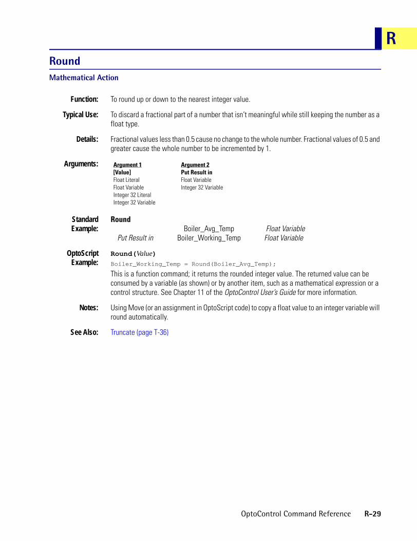
RRoundMathematical Action
Function: To round up or down to the nearest integer value.
Typical Use: To discard a fractional part of a number that isn’t meaningful while still keeping the number as a float type.
Details: Fractional values less than 0.5 cause no change to the whole number. Fractional values of 0.5 and greater cause the whole number to be incremented by 1.
Arguments:
StandardExample:
RoundBoiler_Avg_Temp Float Variable
Put Result in Boiler_Working_Temp Float Variable
OptoScriptExample:
Round(Value)Boiler_Working_Temp = Round(Boiler_Avg_Temp);
This is a function command; it returns the rounded integer value. The returned value can be consumed by a variable (as shown) or by another item, such as a mathematical expression or a control structure. See Chapter 11 of the OptoControl User’s Guide for more information.
Notes: Using Move (or an assignment in OptoScript code) to copy a float value to an integer variable will round automatically.
See Also: Truncate (page T-36)
Argument 1[Value]Float LiteralFloat VariableInteger 32 LiteralInteger 32 Variable
Argument 2Put Result inFloat VariableInteger 32 Variable
OptoControl Command Reference R-29

R-30 OptoControl Command Reference

S
SSeed Random NumberMathematical ActionFunction: To set a random starting point for the random number generator.
Typical Use: • To ensure the random number generator does not generate the same sequence of numbers each time it is started.
• To switch random number sequences on-the-fly by “re-seeding” the random number generator.
Details: This command seeds the random number generator with a millisecond time value which will be unique each time the command is issued.
Arguments: None.
StandardExample:
Seed Random Number
OptoScriptExample:
SeedRandomNumber()SeedRandomNumber();
This is a procedure command; it does not return a value.
See Also: Generate Random Number (page G-5)
OptoControl Command Reference S-1

Set Analog Filter WeightAnalog Point Action
Function: To activate digital filtering and set the amount of filtering to use on an analog input point.
Typical Use: To smooth noisy or erratic input signals.
Details: • Not available on SNAP Ethernet brains.• When issued, this command copies the current input value to the filtered value to initialize
it. Thereafter, a percentage of the difference between the current input value and the last filtered value is added to the last filtered value at the rate of 10 times per second.
• To read the filtered value, use Get Analog Filtered Value, Get & Clear Analog Filtered Value, or Get Analog Square Root Filtered Value. All other commands will read the unfiltered value!
• The digital filtering algorithm is an implementation of a first-order lag filter: New Filtered Value = ( ( Current Reading - Old Filter Value ) / Filter Weight ) + Old Filter Value.
• To calculate the filter weight value that will result in a particular time constant value, use: Filter Weight = (Time Constant [in seconds] + 0.1 ) * 10.A one-second time constant requires a filter weight of 11.
• To calculate the time constant that a particular filter weight will result in, use: Time Constant (in seconds) = (Filter Weight / 10) - 0.1.
• With a filter weight of 11, an input value that suddenly changes from 0 percent to 100 percent (a 100 percent step change) will take over five seconds to be fully recognized. This is considered to be a time constant of one second (which is the time it takes for the input to reach 63.21 percent of its final value), as shown below:
100% Step Change, Filter Weight Of 11Input Value Time In Seconds Value Read
100% 0 0%100% 1 63.21%100% 2 86.47%100% 3 95.02%100% 4 98.17%100% 5 99.33%
• A filter weight value of zero specifies digital filtering is to be discontinued.• The filter weight will be used until power is removed from the I/O unit, or it will always be
used if it is stored in permanent memory at the I/O unit.
Arguments:
StandardExample:
Set Analog Filter WeightTo FILTER_WEIGHT Integer 32 Variable
On Point TEMP_IN1 Analog Input
Argument 1ToFloat LiteralFloat VariableInteger 32 LiteralInteger 32 Variable
Argument 2On PointAnalog Input
S-2 OptoControl Command Reference
SOptoScript
Example:SetAnalogFilterWeight(To, On Point)SetAnalogFilterWeight(FILTER_WEIGHT, TEMP_IN1);
This is a procedure command; it does not return a value.
Notes: • Do not continually issue this command, since it resets the filtered value to the current value.• To ensure that digital filtering will always be active, store this and other changeable I/O unit
values in permanent memory at the I/O unit. (You can do so through Debug mode.)
See Also: Get Analog Filtered Value (page G-30), Get & Clear Analog Filtered Value (page G-10), Get Analog Square Root Filtered Value (page G-34)
OptoControl Command Reference S-3

Set Analog GainAnalog Point Action
Function: To improve accuracy of an analog input signal.
Typical Uses: To improve calibration on a temperature input
Details: • For help in setting offset and gain, see Opto 22 form #1359, Using Offset and Gain Technical Note, available on our Web site at www.opto22.com.
• Always use Set Analog Offset before using this command.• The default gain value is 1.0. The valid range for gain is 0.0003 to 16.0. For example, for a G4
analog input, a gain of 4.0 will cause a 25 percent input value to read 100 percent (full scale).
• The calculated gain will be used until power is removed from the I/O unit, or it will always be used if the gain is stored in permanent memory at the I/O unit.
Arguments:
StandardExample:
Set Analog GainTo GAIN_COEFFICIENT Float Variable
On Point PRESS_IN Analog Input
OptoScriptExample:
SetAnalogGain(To, On Point)SetAnalogGain(GAIN_COEFFICIENT, PRESS_IN);
This is a procedure command; it does not return a value.
Notes: • This procedure should only have to be performed once.• To ensure that the gain will always be used, store this and other changeable I/O unit values
in permanent memory at the I/O unit. (You can do so through Debug mode.)
Dependencies: Must use Set Analog Offset first.
See Also: Set Analog Offset (page S-5), Calculate & Set Analog Gain (page C-1)
Argument 1ToFloat LiteralFloat VariableInteger 32 LiteralInteger 32 Variable
Argument 2On PointAnalog Input
S-4 OptoControl Command Reference

SSet Analog OffsetAnalog Point Action
Function: To improve the accuracy of an analog input signal.
Typical Uses: To improve calibration on a temperature input.
Details: • For help in setting offset and gain, see Opto 22 form #1359, Using Offset and Gain Technical Note, available on our Web site at www.opto22.com.
• Always use Set Analog Gain after using this command.• The default offset value is 0. The valid range for offset varies by type, as shown below:
• For non-Ethernet brains, offset and gain are in units of raw counts. For example, for a G4 analog input, an offset of -1,024 causes a 25 percent input value to read 0 percent (zero scale).
• For Ethernet brains, offset and gain are in engineering units. For example, an offset of 1 affects actual input by one degree F. or C.
• The calculated offset will be used until power is removed from the I/O unit, or it will always be used if the offset is stored in permanent memory at the I/O unit.
Arguments:
StandardExample:
Set Analog OffsetTo OFFSET Integer 32 Variable
On Point PRESS_IN Analog Input
OptoScriptExample:
SetAnalogOffset(To, On Point)SetAnalogOffset(OFFSET, PRESS_IN);
This is a procedure command; it does not return a value.
Notes: • This procedure should only have to be performed once.• To ensure that the offset will always be used, store this and other changeable I/O unit
values in permanent memory at the I/O unit. (You can do so through Debug mode.)
See Also: Set Analog Gain (page S-4), Calculate & Set Analog Offset (page C-3)
G4 analog (not high density) -4,095 to 4,095 (integer values only)
G4 high density (such as G4HDAR) 0 to 65,535
Serial SNAP brains -25,000 to +25,000
SNAP Ethernet brains Any floating point number
Argument 1ToFloat LiteralFloat VariableInteger 32 LiteralInteger 32 Variable
Argument 2On PointAnalog Input
OptoControl Command Reference S-5
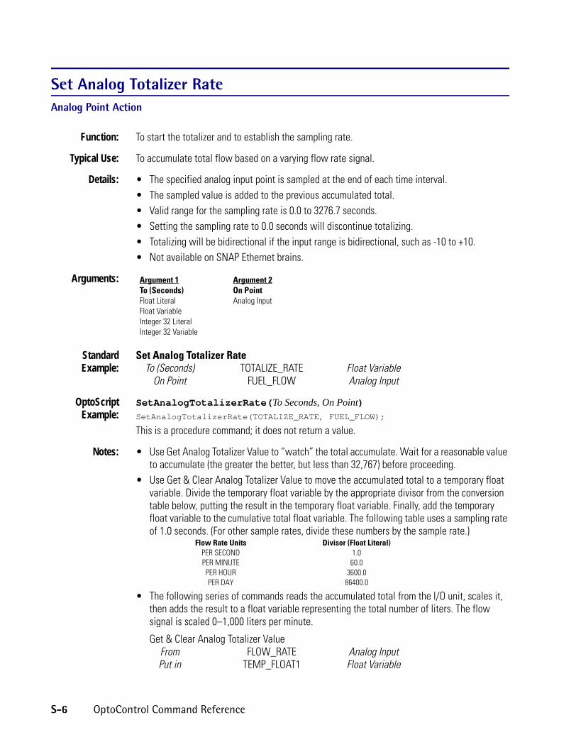
Set Analog Totalizer RateAnalog Point Action
Function: To start the totalizer and to establish the sampling rate.
Typical Use: To accumulate total flow based on a varying flow rate signal.
Details: • The specified analog input point is sampled at the end of each time interval.• The sampled value is added to the previous accumulated total.• Valid range for the sampling rate is 0.0 to 3276.7 seconds.• Setting the sampling rate to 0.0 seconds will discontinue totalizing.• Totalizing will be bidirectional if the input range is bidirectional, such as -10 to +10.• Not available on SNAP Ethernet brains.
Arguments:
StandardExample:
Set Analog Totalizer RateTo (Seconds) TOTALIZE_RATE Float Variable
On Point FUEL_FLOW Analog Input
OptoScriptExample:
SetAnalogTotalizerRate(To Seconds, On Point)SetAnalogTotalizerRate(TOTALIZE_RATE, FUEL_FLOW);
This is a procedure command; it does not return a value.
Notes: • Use Get Analog Totalizer Value to “watch” the total accumulate. Wait for a reasonable value to accumulate (the greater the better, but less than 32,767) before proceeding.
• Use Get & Clear Analog Totalizer Value to move the accumulated total to a temporary float variable. Divide the temporary float variable by the appropriate divisor from the conversion table below, putting the result in the temporary float variable. Finally, add the temporary float variable to the cumulative total float variable. The following table uses a sampling rate of 1.0 seconds. (For other sample rates, divide these numbers by the sample rate.)
Flow Rate Units Divisor (Float Literal)PER SECOND 1.0PER MINUTE 60.0PER HOUR 3600.0PER DAY 86400.0
• The following series of commands reads the accumulated total from the I/O unit, scales it, then adds the result to a float variable representing the total number of liters. The flow signal is scaled 0–1,000 liters per minute.
Get & Clear Analog Totalizer ValueFrom FLOW_RATE Analog InputPut in TEMP_FLOAT1 Float Variable
Argument 1To (Seconds)Float LiteralFloat VariableInteger 32 LiteralInteger 32 Variable
Argument 2On PointAnalog Input
S-6 OptoControl Command Reference

SDivide Temp_Float1
By 60.0Put Result in TEMP_FLOAT1 Float Variable
Do Add Temp_Float1Plus LITERS
Put Result in LITERS Float Variable
See Also: Get Analog Totalizer Value (page G-36), Get & Clear Analog Totalizer Value (page G-13)
OptoControl Command Reference S-7

Set Analog TPO PeriodAnalog Point Action
Function: To set the time proportional output period of an analog point where the analog TPO module is used.
Typical Use: To control the duty cycle of resistive heating elements used for temperature control.
Details: • Analog points will not function as TPOs until this command is issued.• For a G4DA9 module, TPO periods are multiples of 2.048 seconds (for example, 2.048, 4.096,
6.144,) ranging from 2.048 to 522.2 seconds. If the value entered is not an exact multiple of 2.048 seconds, it is rounded to the nearest period value.
• For a SNAP-AOD-29 module, TPO periods are multiples of 0.251 seconds, ranging from 0.251 to 64.25 seconds. If the value entered is not an exact multiple, it is rounded to the nearest period value.
• The time proportion period specifies the total time the output is varied.• Use Move to set the percent of on time by moving a value from 0–100 to the analog
output point.• Always use 0–100 for the analog TPO scaling.• PID outputs can be analog TPO points.
Arguments:
StandardExample:
This example sets the period for the TPO point named TPO OUTPUT to 6.144 seconds (the value 6.0 is rounded automatically to the nearest period value, 6.144). If Move is used to set a 50 percent duty cycle (by Moving 50.0 to TPO OUTPUT), then the analog output will repeatedly cycle on for 3.072 seconds and off for 3.072 seconds.
Set Analog TPO PeriodTo (Seconds) 6.0 Float Literal
On Point TPO_OUTPUT Analog Input
OptoScriptExample:
SetAnalogTpoPeriod(To, On Point)SetAnalogTpoPeriod(6.0, TPO_OUTPUT);
This is a procedure command; it does not return a value.
Notes: • To ensure that the TPO period will always be correct, store this and other changeable I/O unit values in permanent memory at the I/O unit. (You can do so through Debug mode.)
• If the TPO period is not stored in permanent memory at the I/O unit, use Set Analog TPO Period immediately before Moving a new value to the TPO every time. This ensures that the TPO period will be configured properly if the I/O unit has experienced loss of power. Do not,
Argument 1To (Seconds)Float LiteralFloat VariableInteger 32 LiteralInteger 32 Variable
Argument 2On PointAnalog Output
S-8 OptoControl Command Reference

Showever, issue these commands more frequently than necessary since this can be counterproductive.
Dependencies: This command is valid only when used on a properly configured time proportional output module.
Set ARCNET Host Destination AddressCommunication—Network Action
Function: To set the destination address of the next ARCNET message to be sent to the host.NOTE: The newer command Set ARCNET Destination Address on Port is preferred, as it provides the option to use other ports. This command is still supported for older strategies.
Typical Use: To direct an ARCNET host message to an address other than the address of the last ARCNET host message received.
Details: • No need to use this command when the destination is the same as the last ARCNET host message received.
• All references to ARCNET host use port 4.
Arguments:
StandardExample:
Set ARCNET Host Destination AddressTo ARCNET_HOST Integer 32 Variable
OptoScriptExample:
SetArcnetHostDestAddress(To)SetArcnetHostDestAddress(ARCNET_HOST);
This is a procedure command; it does not return a value.
Notes: • See “Communication—Network Commands” in Chapter 10 of the OptoControl User’s Guide.• Always use this command after receiving an ARCNET host message unless responding to
the source of the message.
See Also: Get ARCNET Host Destination Address (page G-38)
Argument 1ToInteger 32 LiteralInteger 32 Variable
OptoControl Command Reference S-9

Set ARCNET Destination Address on PortCommunication—Network Action
Function: On the specified port, to set the destination address of the next ARCNET message to be sent.
Typical Use: To direct an ARCNET message to an address other than the address of the last ARCNET message received.
Details: No need to use this command when the destination is the same as the last ARCNET message received.
Arguments:
StandardExample:
Set ARCNET Destination Address on PortTo Address ARCNET_DEST Integer 32 Variable
On Port ARCNET_PORT Integer 32 Variable
OptoScriptExample:
SetArcnetDestAddressOnPort(To Address, On Port)SetArcnetDestAddressOnPort(ARCNET_DEST, ARCNET_PORT);
This is a procedure command; it does not return a value.
Notes: • See “Communication—Network Commands” in Chapter 10 of the OptoControl User’s Guide.• Always use this command after receiving an ARCNET message unless responding to the
source of the message.
See Also: Get ARCNET Destination Address on Port (page G-39)
Argument 1To AddressInteger 32 LiteralInteger 32 Variable
Argument 2On PortInteger 32 LiteralInteger 32 Variable
S-10 OptoControl Command Reference

SSet ARCNET Mode RawCommunication—Network Action
Function: Switches to a lower-level mode where the user has full access to the ARCNET packet header bytes.
Typical Use: To enable the controller to act as a network master or as an ARCNET pass-through device.
Details: While in raw mode, you must send the following bytes. Also, these bytes will be in any message received on either port 4 or port 7. • First byte is the Opto 22 vendor ID. It must be DA hex (218 decimal).• Second byte is:
0 = normal. Use when originating or responding to a PC or to port 4 on another controller.
1 = normal with packet ID numbers. Use when sending to a PC or to port 4 on another controller. Not for use with peer mode.
7 = peer. Use when sending to the peer port on another controller.
-x = normal response error code. Type is a signed short integer. Not for use with peer.• Third byte is the packet ID only if the second byte = 1.
Arguments:
StandardExample:
Set ARCNET Mode RawPut Result in MODE_STATUS Integer 32 Variable
OptoScriptExample:
SetArcnetModeRaw()MODE_STATUS = SerArcnetModeRaw();
This is a function command; it returns one of the status codes listed below.
Notes: Use Set ARCNET Mode Standard to switch modes.
Status Codes: 0 = No error-40 = Lock Port Timeout-82 = No ARCNET card
See Also: Set ARCNET Mode Standard (page S-12)
Argument 1Put Result inFloat VariableInteger 32 Variable
OptoControl Command Reference S-11

Set ARCNET Mode StandardCommunication—Network Action
Function: Switches to the normal higher-level mode where the ARCNET packet header bytes are handled automatically.
Typical Use: This is the factory default mode.
Details: Under normal conditions this mode is the desired mode since all the details are handled automatically.
Arguments:
StandardExample:
Set ARCNET Mode StandardPut Result in MODE_STATUS Integer 32 Variable
OptoScriptExample:
SetArcnetModeStandard()MODE_STATUS = SetArcnetModeStandard();
This is a function command; it returns one of the status codes listed below.
Status Codes: 0 = No error-40 = Lock Port Timeout-82 = No ARCNET card
Notes: Use Set ARCNET Mode Raw to switch modes.
See Also: Set ARCNET Mode Raw (page S-11)
Argument 1Put Result inFloat VariableInteger 32 Variable
S-12 OptoControl Command Reference

SSet ARCNET Peer Destination AddressCommunication—Network Action
Function: To set the destination address of the next peer message to be sent.
Typical Use: To direct a peer message to an address other than the address of the last peer message received.
Details: • No need to use this command when the destination is the same as the last peer message received.
• All references to peer use port 7, which is a special gateway to the ARCNET cable.
Arguments:
StandardExample:
Set ARCNET Peer Destination AddressTo PEER_DEST Integer 32 Variable
OptoScriptExample:
SetArcnetPeerDestAddress(To)SetArcnetPeerDestAddress(PEER_DEST);
This is a procedure command; it does not return a value.
Notes: • See “Communication—Network Commands” in Chapter 10 of the OptoControl User’s Guide.• Always use this command after receiving a peer message unless responding to the source of
the message.
See Also: Get ARCNET Peer Destination Address (page G-40)
Argument 1ToInteger 32 LiteralInteger 32 Variable
OptoControl Command Reference S-13

Set DateTime/Date Action
Function: To set the date in the controller’s real-time clock/calendar to the value contained in a string variable, using the standard United States format mm/dd/yy, where mm = month (01–12), dd = day (01–31), and yy = year (00–99).
Typical Use: To set the date from an OptoControl program.
Details: • The destination can be a string variable or a string literal.• If the desired date to set is March 1, 2000, the To parameter (Argument 1) should contain the
string “03/01/00.”• Executing this command would set the controller’s real-time clock/calendar to March 1,
2000.• Updates day of week also.• All erroneous date strings are ignored.
Arguments:
StandardExample:
Set DateTo US_DATE_STRING String Variable
OptoScriptExample:
SetDate(To)SetDate(US_DATE_STRING);
This is a procedure command; it does not return a value.
Notes: • In Debug mode OptoControl always sets the date, time, and day of week to the PC clock at the end of a download.
• To change the date, use an integer variable as a change trigger. Set the trigger variable True after the date string has the desired value. When the trigger is True, the program executes this command, then sets the trigger variable False.
• The controller’s real-time clock/calendar will automatically increment the time and date after they are set.
• Do not issue this command continuously.
See Also: Copy Date to String (DD/MM/YY) (page C-60), Copy Date to String (MM/DD/YY) (page C-61), Copy Time to String (page C-62)
Argument 1ToString LiteralString Variable
S-14 OptoControl Command Reference

SSet DayTime/Date Action
Function: To set the day of the month (1 through 31) in the controller’s real-time clock/calendar.
Typical Use: To set the day of the month from an OptoControl program.
Details: • The To parameter (Argument 1) can be an integer or a float, although an integer is preferred.• If the desired day of the month to set is March 2, 1999, the To parameter (Argument 1)
should contain the value 2.• Executing this command would then set the day of the month in the controller’s real-time
clock/calendar.• Updates day of week also.• All erroneous day values are ignored.
Arguments:
StandardExample:
Set DayTo DAY_OF_MONTH Integer 32 Variable
OptoScriptExample:
SetDay(To)SetDay(DAY_OF_MONTH);
This is a procedure command; it does not return a value.
Notes: • Use to change the DAY to test program logic. Use an integer variable as a change trigger. Set the trigger variable True after the DAY_OF_MONTH variable has the desired value. When the trigger is True, the program executes this command, then sets the trigger variable False.
• Do not issue this command continuously.
See Also: Get Day (page G-45), Get Day of Week (page G-46), Get Hours (page G-59), Get Minutes (page G-64), Get Month (page G-66), Get Seconds (page G-98), Get Year (page G-105), Set Day of Week (page S-16), Set Hours (page S-21), Set Minutes (page S-23), Set Month (page S-25), Set Seconds (page S-41) Set Year (page S-49)
Argument 1ToFloat LiteralFloat VariableInteger 32 LiteralInteger 32 Variable
OptoControl Command Reference S-15

Set Day of WeekTime/Date Action
Function: To set the day of the week value (0 through 6) in the controller’s real-time clock/calendar. (This command does not work with OptoRuntimePC.)
Typical Use: To set the day of the week from an OptoControl program.
Details: • The To parameter (Argument 1) can be an integer or a float, although an integer is preferred.• Days are numbered as follows:
• If the desired day of week to set is Wednesday, then the To parameter (Argument 1) should contain the value 3.
• Executing this command would set the day of the week in the controller’s real-time clock/calendar.
• All erroneous day-of-week values are ignored.
Arguments:
StandardExample:
Set Day of WeekTo DAY_OF_WEEK Integer 32 Variable
OptoScriptExample:
SetDayOfWeek(To)SetDayOfWeek(DAY_OF_WEEK);
This is a procedure command; it does not return a value.
Notes: • Use to change the day of the week to test program logic. Use an integer variable as a change trigger. Set the trigger variable True after the To parameter (DAY_OF_WEEK, in the example above) has the desired value. When the trigger is True, the program executes this command, then sets the trigger variable False.
• Do not issue this command continuously.• Use this command with extreme care and only for testing. When finished testing, make sure
the day of the week matches what it should be for the actual date.
See Also: Get Day (page G-45), Get Day of Week (page G-46), Get Hours (page G-59), Get Minutes (page G-64), Get Month (page G-66), Get Seconds (page G-98), Get Year (page G-105), Set Day (page S-15), Set Hours (page S-21), Set Minutes (page S-23), Set Month (page S-25), Set Seconds (page S-41) Set Year (page S-49)
Sunday = 0Monday = 1Tuesday = 2Wednesday = 3
Thursday = 4Friday = 5Saturday = 6
Argument 1ToFloat LiteralFloat VariableInteger 32 LiteralInteger 32 Variable
S-16 OptoControl Command Reference

SSet Digital I/O Unit from MOMO MasksI/O Unit Action
Function: To control multiple digital output points on the same I/O unit simultaneously with a single command.
Typical Use: To efficiently control a selected group of digital outputs with one command.
Details: • This command is 16 times faster than using Turn On or Turn Off 16 times.• Updates the IVALs and XVALs for all 16 points. Affects only selected output points. Does not
affect input points.• Uses only the lowest (least significant) 16 bits of the integer. The least significant bit
corresponds to point zero.• A point is selected for activation by setting the respective bit in the 16-bit data field of
argument 1 (the must-on bit mask) to a value of “1.” A point is selected for deactivation by setting the respective bit in the 16-bit data field of argument 2 (the must-off bit mask) to a value of “1.” Any bits set to a value of 0 in both arguments 1 and 2 will leave those points unaffected.
• If a specific point is disabled or if the entire I/O unit is disabled, only the internal values (IVALs) will be written.
Arguments:
StandardExample:
Set Digital I/O Unit from MOMO MasksMust On Mask PUMPS_ON_MASK Integer 32 VariableMust Off Mask 3840 Integer 32 LiteralDigital I/O Unit PUMP_CTRL B3000 SNAP Digital
The effect of this command is illustrated below:
In this example, points 4, 5, 6, and 7 will be turned on. Points 8, 9, 10, and 11 will be turned off. Points 0, 1, 2, 3, 12, 13, 14, and 15 are not changed.
OptoScriptExample:
SetDigitalIoUnitFromMomo(Must-On Mask, Must-Off Mask, Digital I/O Unit)SetDigitalIoUnitFromMomo(PUMPS_ON_MASK, 3840, PUMP_CTRL);
Argument 1Must On MaskInteger 32 LiteralInteger 32 Variable
Argument 2Must Off MaskInteger 32 LiteralInteger 32 Variable
Argument 3Digital I/O UnitB100 Digital Multifunction I/O UnitB3000 SNAP DigitalB3000 SNAP Mixed I/OG4 Digital Local Simple I/O UnitG4 Digital Multifunction I/O UnitG4 Digital Remote Simple I/O UnitSNAP Remote Simple Digital
Point Number 15 14 13 12 11 10 9 8 7 6 5 4 3 2 1 0
Must-on Bit Mask
Binary 0 0 0 0 0 0 0 0 1 1 1 1 0 0 0 0
Hex 0 0 F 0
Must-off Bit Mask
Binary 0 0 0 0 1 1 1 1 0 0 0 0 0 0 0 0
Hex 0 F 0 0
OptoControl Command Reference S-17

This is a procedure command; it does not return a value.
Notes: • For a 64-point digital-only rack, use the command Set Digital-64 I/O Unit from MOMO Masks.
• Use Bit Set or Bit Clear to change individual bits in an integer variable.
See Also: Get Digital I/O Unit as Binary Value (page G-48)
Set Digital-64 I/O Unit from MOMO MasksI/O Unit Action
Function: To control multiple digital output points on the same 64-point digital-only I/O unit simultaneously with a single command.
Typical Use: To efficiently control all digital outputs on a 64-point digital rack with one command.
Details: • This command is 64 times faster than using Turn On or Turn Off 64 times.• Updates the IVALs and XVALs for all 64 points. Affects only selected output points. Does not
affect input points.• A point is selected for activation by setting the respective bit in the 64-bit data field of
argument 1 (the must-on bit mask) to a value of “1.” A point is selected for deactivation by setting the respective bit in the 64-bit data field of argument 2 (the must-off bit mask) to a value of “1.” Any bits set to a value of 0 in both arguments 1 and 2 will leave those points unaffected.
• The least significant bit corresponds to point zero.• If a specific point is disabled or if the entire I/O unit is disabled, only the internal values
(IVALs) will be written.
Arguments:
StandardExample:
Set Digital-64 I/O Unit from MOMO MasksMust On Mask PUMPS_ON_MASK Integer 64 VariableMust Off Mask 0xB0F240010308A020 Integer 64 Literal
Digital-64 I/O Unit PUMP_CTRL_UNIT SNAP Digital 64The effect of this command is illustrated below:
Argument 1Must On MaskInteger 64 LiteralInteger 64 Variable
Argument 2Must Off MaskInteger 64 LiteralInteger 64 Variable
Argument 3Digital-64 I/O UnitSNAP Digital 64
Point Number 63 62 61 60 59 58 57 56 7 6 5 4 3 2 1 0
Must-on Bit Mask
Binary 0 0 0 0 0 1 1 0 1 1 0 0 0 0 1 0
Hex 0 6 C 2
Must-off Bit Mask
Binary 1 0 1 1 0 0 0 0 0 0 1 0 0 0 0 0
Hex B 0 2 0
S-18 OptoControl Command Reference

STo save space, the example shows only the first eight points and the last eight points on the rack. For the points shown, points 58, 57, 7, 6, and 1 will be turned on. Points 63, 61, 60, and 5 will be turned off. Other points shown are not changed.
OptoScriptExample:
SetDigital64IoUnitFromMomo(Must-On Mask, Must-Off Mask, Digital-64 I/O Unit)SetDigital64IoUnitFromMomo(PUMPS_ON_MASK, 0xB0F240010308A020i64,
PUMP_CTRL_UNIT);
This is a procedure command; it does not return a value. (Note that Integer 64 literals in OptoScript code take an i64 suffix.
Notes: Use Bit Set or Bit Clear to change individual bits in an integer variable.
See Also: Get Digital-64 I/O Unit as Binary Value (page G-49)
Set Down Timer Preset ValueMiscellaneous Action
Function: To set the value from which a down timer counts down.
Typical Use: To initialize a down timer.
Details: • This command sets the value from which a down timer counts down, but it does not start the timer. To start the timer counting down, use the command Start Timer.
• The preset value will be persistent between calls to Start Timer.• Argument 1 must be a positive number in seconds.
Arguments:
StandardExample:
Set Down Timer Preset ValueTarget Value 60.0 Float LiteralDown Timer OVEN_TIMER Down Timer Variable
OptoScriptExample:
SetDownTimerPreset(Target Value, Down Timer)SetDownTimerPreset(60.0, OVEN_TIMER);
This is a procedure command; it does not return a value.
Notes: • See “Miscellaneous Commands” in Chapter 10 of the OptoControl User’s Guide for more information on using timers.
• To set the preset value and start the timer in one step, use the Move command to move the preset value to the timer. The timer will immediately start counting down from the value moved to it. Using Move overwrites any preset value previously set, so subsequent Start Timer commands will start from the value most recently moved.
See Also: Start Timer (page S-62), Stop Timer (page S-68), Continue Timer (page C-45), Pause Timer (page P-1), Down Timer Expired? (page D-22)
Argument 1Target ValueFloat LiteralFloat Variable
Argument 2Down TimerDown Timer Variable
OptoControl Command Reference S-19

Set End-of-Message TerminatorCommunication—Serial Action
Function: Defines the character that will be used to determine end-of-message for a specific chart.
Typical Use: Used by Receive String via Serial Port and Transmit/Receive String via Serial Port to determine end-of-message.
Details: • A carriage return (character 13) is the factory default end-of-message terminator. If the equipment you use requires a different terminator, use this command to change it. Valid range is 0–255.
• The end-of-message terminator is discarded as the message is removed from the receive buffer.
• This command only needs to be used once in the specified chart that contains the serial commands Receive String via Serial Port and Transmit/Receive String via Serial Port. The command applies to the whole chart, not to a specific piece of equipment.
Arguments:
StandardExample:
Set End-of-Message TerminatorTo Character 10 Integer 32 Literal
OptoScriptExample:
SetEndOfMessageTerminator(To Character)SetEndOfessageTerminator(10);
This is a procedure command; it does not return a value.
Notes: • When receiving messages that are terminated with a carriage return (character 13) and a line feed (character 10), use 10 for the terminator.
• This command is NOT global to the entire program. Typically, this command is used in Block 0 of the appropriate chart or charts. It applies to the whole chart in which it is used, not to an individual piece of equipment. If necessary, use one chart or a subroutine for one piece of equipment.
• The host task always uses a carriage return as a terminator. You cannot change the terminator for a host task.
See Also: Receive String via Serial Port (page R-21), Transmit/Receive String via Serial Port (page T-34)
Argument 1To CharacterInteger 32 LiteralInteger 32 Variable
S-20 OptoControl Command Reference

SSet HoursTime/Date Action
Function: To set the hours value (0 through 23) in the controller’s real-time clock/calendar.
Typical Use: To set the hours value from an OptoControl program.
Details: • The To parameter (Argument 1) can be an integer or a float, although an integer is preferred.• Time is in 24-hour format. For example, 8 a.m. = 08:00:00, 1 p.m. = 13:00:00, and
11:59:00 p.m. = 23:59:00.• If the desired hour to set is 2 p.m. (14:00:00), the To parameter (Argument 1) should contain
the value 14.• Executing this command would set the hours value in the controller’s real-time
clock/calendar.• The controller’s real-time clock/calendar will automatically increment the time and date
after they are set.• All erroneous hour values are ignored.
Arguments:
StandardExample:
Set HoursTo HOURS Integer 32 Variable
OptoScriptExample:
SetHours(To)SetHour(HOURS);
This is a procedure command; it does not return a value.
Notes: • Use to change the HOUR to test program logic. Use an integer variable as a change trigger. Set the trigger variable True after the HOURS variable has the desired value. When the trigger is True, the program executes this command, then sets the trigger variable False.
• Do not issue this command continuously.
See Also: Get Day (page G-45), Get Day of Week (page G-46), Get Hours (page G-59), Get Minutes (page G-64), Get Month (page G-66), Get Seconds (page G-98), Get Year (page G-105), Set Day of Week (page S-16), Set Day (page S-15), Set Minutes (page S-23), Set Month (page S-25), Set Seconds (page S-41) Set Year (page S-49)
Argument 1ToFloat LiteralFloat VariableInteger 32 LiteralInteger 32 Variable
OptoControl Command Reference S-21

Set I/O Unit Configured FlagI/O Unit Action
Function: Sets a flag internal to the controller to indicate that the I/O unit has been initialized by the controller.
Typical Use: Where there is a standby controller configured to take over communication to the I/O units in the event of a primary controller failure.
Details: • This command should be issued for each I/O unit, preferably in the Powerup chart. Use it in both the primary and standby controller programs to keep them the same.
• By default, the controller assumes it is the only controller attached to the I/O and therefore must configure each I/O unit. This command makes the standby controller think it has already configured all the I/O units, which allows it to begin communicating with the I/O units immediately and without disrupting any control being performed by the I/O units (assuming it has just taken over as the primary). This command has no effect in a controller that has already established communication with the I/O units.
Arguments:
StandardExample:
Set I/O Unit Configured FlagFor I/O Unit FURNACE_PID G4 Digital Remote Simple I/O Unit
OptoScriptExample:
SetIoUnitConfiguredFlag(For I/O Unit)SetIOUnitConfiguredFlag(FURNACE_PID);
This is a procedure command; it does not return a value.
Notes: Any I/O units that actually need configuring will still be configured since they notify the controller of the need.
See Also: Configure I/O Unit (page C-40)
Argument 1For I/O UnitB100 Digital Multifunction I/O UnitB200 Analog Multifunction I/O UnitB3000 SNAP AnalogB3000 SNAP DigitalB3000 SNAP Mixed I/OG4 Analog Multifunction I/O UnitG4 Digital Local Simple I/O UnitG4 Digital Multifunction I/O UnitG4 Digital Remote Simple I/O UnitHRD Analog Current Output I/O UnitHRD Analog RTD Input I/O UnitHRD Analog Thermocouple/mV Input I/O UnitHRD Analog Voltage Output I/O UnitHRD Analog Voltage/Current Input I/O UnitSNAP Digital 64SNAP Remote Simple Digital
S-22 OptoControl Command Reference

SSet MinutesTime/Date Action
Function: To set the minutes value (0 through 59) in the controller’s real-time clock/calendar.
Typical Use: To set the minutes value from an OptoControl program.
Detail: • The To parameter (Argument 1) can be an integer or a float, although an integer is preferred.• Time is in 24-hour format. For example, 8 a.m. = 08:00:00, 1 p.m. = 13:00:00, and 11:59:00
p.m. = 23:59:00.• If the desired time to set is 2:35 p.m. (14:35:00), the To parameter (Argument 1) should
contain the value 35.• Executing this command would set the minutes value in the controller’s real-time
clock/calendar.• The controller’s real-time clock/calendar will automatically increment the time and date
after they are set.• All erroneous values for minutes are ignored.
Arguments:
StandardExample:
Set MinutesTo MINUTES Integer 32 Variable
OptoScriptExample:
SetMinutes(To)SetMinutes(MINUTES);
This is a procedure command; it does not return a value.
Notes: • Use to change the MINUTES to test program logic. Use an integer variable as a change trigger. Set the trigger variable True after the MINUTES variable has the desired value. When the trigger is True, the program executes this command, then sets the trigger variable False.
• Do not issue this command continuously.
See Also: Get Day (page G-45), Get Day of Week (page G-46), Get Hours (page G-59), Get Minutes (page G-64), Get Month (page G-66), Get Seconds (page G-98), Get Year (page G-105), Set Day of Week (page S-16), Set Hours (page S-21), Set Day (page S-15), Set Month (page S-25), Set Seconds (page S-41) Set Year (page S-49)
Argument 1ToFloat LiteralFloat VariableInteger 32 LiteralInteger 32 Variable
OptoControl Command Reference S-23

Set Mixed I/O Unit from MOMO MasksI/O Unit Action
Function: To control multiple digital output points on the same mixed I/O unit simultaneously with a single command.
Typical Use: To efficiently control all digital outputs on a mixed I/O rack with one command.
Details: • This command is 32 times faster than using Turn On or Turn Off 32 times.• Updates the IVALs and XVALs for all 32 digital points. Affects only selected digital output
points. Does not affect digital input points. Does not affect analog points in any position on the rack.
• A point is selected for activation by setting the respective bit in the 32-bit data field of Argument 1 (the must-on bit mask) to a value of “1.” A point is selected for deactivation by setting the respective bit in the 32-bit data field of Argument 2 (the must-off bit mask) to a value of “1.” Any bits set to a value of 0 in both arguments 1 and 2 will leave those points unaffected.
• The least significant bit corresponds to point zero.• If a specific point is disabled or if the entire I/O unit is disabled, only the internal values
(IVALs) will be written.
Arguments:
StandardExample:
Set Mixed I/O Unit from MOMO MasksMust On Mask PUMPS_ON_MASK Integer 32 VariableMust Off Mask 0xB001A020 Integer 32 LiteralMixed I/O Unit PUMP_CTRL_UNIT B3000 SNAP Mixed I/O
The effect of this command is illustrated below:
To save space, the example shows only the first eight and the last eight digital points on the rack. For the points shown, points 26, 25, 7, 6, and 1 will be turned on. Points 31, 29, 28, and 5 will be turned off. Other points shown are not changed.
OptoScriptExample:
SetMixedIoUnitFromMomo(Must-On Mask, Must-Off Mask, Mixed I/O Unit)SetMixedIoUnitFromMomo(PUMPS_ON_MASK, 0xB001A020, PUMP_CTRL_UNIT);
This is a procedure command; it does not return a value.
Argument 1Must On MaskInteger 32 LiteralInteger 32 Variable
Argument 2Must Off MaskInteger 32 LiteralInteger 32 Variable
Argument 3Mixed I/O UnitB3000 SNAP Mixed I/O
Point Number 31 30 29 28 27 26 25 24 7 6 5 4 3 2 1 0
Must-on Bit Mask
Binary 0 0 0 0 0 1 1 0 1 1 0 0 0 0 1 0
Hex 0 6 C 2
Must-off Bit Mask
Binary 1 0 1 1 0 0 0 0 0 0 1 0 0 0 0 0
Hex B 0 2 0
S-24 OptoControl Command Reference
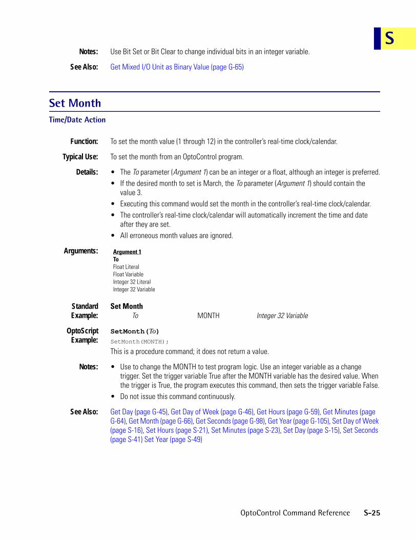
SNotes: Use Bit Set or Bit Clear to change individual bits in an integer variable.
See Also: Get Mixed I/O Unit as Binary Value (page G-65)
Set MonthTime/Date Action
Function: To set the month value (1 through 12) in the controller’s real-time clock/calendar.
Typical Use: To set the month from an OptoControl program.
Details: • The To parameter (Argument 1) can be an integer or a float, although an integer is preferred.• If the desired month to set is March, the To parameter (Argument 1) should contain the
value 3.• Executing this command would set the month in the controller’s real-time clock/calendar.• The controller’s real-time clock/calendar will automatically increment the time and date
after they are set.• All erroneous month values are ignored.
Arguments:
StandardExample:
Set MonthTo MONTH Integer 32 Variable
OptoScriptExample:
SetMonth(To)SetMonth(MONTH);
This is a procedure command; it does not return a value.
Notes: • Use to change the MONTH to test program logic. Use an integer variable as a change trigger. Set the trigger variable True after the MONTH variable has the desired value. When the trigger is True, the program executes this command, then sets the trigger variable False.
• Do not issue this command continuously.
See Also: Get Day (page G-45), Get Day of Week (page G-46), Get Hours (page G-59), Get Minutes (page G-64), Get Month (page G-66), Get Seconds (page G-98), Get Year (page G-105), Set Day of Week (page S-16), Set Hours (page S-21), Set Minutes (page S-23), Set Day (page S-15), Set Seconds (page S-41) Set Year (page S-49)
Argument 1ToFloat LiteralFloat VariableInteger 32 LiteralInteger 32 Variable
OptoControl Command Reference S-25

Set Nth CharacterString Action
Function: Changes a character within a string.
Typical Use: When building communication strings prior to sending.
Details: • The character can be written to any position from 1 up to the current string length.• Valid range for the character is 0–255.
Arguments:
StandardExample:
Set Nth CharacterTo 62 Integer 32 Literal
In String MSG_RECEIVED String VariableAt Index POSITION Integer 32 Variable
Put Status In STATUS Integer 32 Variable
OptoScriptExample:
SetNthCharacter(To, In String, At Index)STATUS = SetNthCharacter(62, MSG_RECEIVED, POSITION);
This is a function command; it returns one of the status codes listed below.
Notes: • A status of zero indicates success.• The string could initially be filled with nulls or spaces up to its declared length to avoid
“string too short” errors.
Status Codes: 0 = Command successful-46 = Incorrect limit
See Also: Find Character in String (page F-1), Get Nth Character (page G-69)
Argument 1ToInteger 32 LiteralInteger 32 Variable
Argument 2In StringString Variable
Argument 3At IndexInteger 32 LiteralInteger 32 Variable
Argument 4Put Status InFloat VariableInteger 32 Variable
S-26 OptoControl Command Reference

SSet Number of Retries to All I/O UnitsI/O Unit Action
Function: To change the factory default retry setting.
Typical Use: To change the number of retries performed when there is a communication error.
Details: • The factory default is two retries, which results in a total of three attempts in succession before reporting an error.
• This setting affects all communication ports simultaneously.• This setting has no effect on Ethernet I/O units. Retries are built into Ethernet TCP/IP.
Arguments:
StandardExample:
Set Number of Retries to All I/O UnitsTo 3 Integer 32 Literal
OptoScriptExample:
SetNumberOfRetriesToAllIoUnits(To)SetNumberOfRetriesToAllIoUnits(3);
This is a procedure command; it does not return a value.
Notes: • See “I/O Unit Commands” in Chapter 10 of the OptoControl User’s Guide.• The default number of retries (two) is more than adequate for most situations.• Before using this command, make sure the timeout value is long enough. See Notes under
Configure Port Timeout Delay for details.
See Also: Configure Port Timeout Delay (page C-42)
Argument 1ToInteger 32 LiteralInteger 32 Variable
OptoControl Command Reference S-27

Set PC Byte Swap Mode (ISA only)Controller Action
Function: Changes the mode of the ISA controller PC bus driver to accommodate certain PC bus peculiarities.
Typical Use: The need for this command will present itself when it is discovered that writes to odd addresses over the PC bus don’t work properly, while writes to even addresses work OK.
Details: Issuing this command once at the start of the user program will alleviate the problem. For PCs that don’t require any modification to the bus driver, use Clear PC Byte Swap Mode (ISA only) or use nothing at all.
Arguments: None.
StandardExample:
Set PC Byte Swap Mode (ISA only)
OptoScriptExample:
SetPcByteSwapMode()SetPcByteSwapMode();
This is a procedure command; it does not return a value.
See Also: Clear PC Byte Swap Mode (ISA only) (page C-30)
S-28 OptoControl Command Reference

SSet PID Control WordPID Action
Function: Change the bits that control the PID operation.
Typical Use: To alter the PID configuration.
Details: • Bit assignments:
11 1 = Use SqRt value from input point.
10 1 = Setpoint was above high clamp. Write zero to clear.
9 1 = Setpoint was below low clamp. Write zero to clear.
8 1 = Input point under-range. Write zero to clear.
7 1 = Loop active. 0 = Loop stopped.
6 1 = Loop in auto mode. 0 = Loop in manual mode.
5 1 = Output active. 0 = Output disconnected.
4 1 = Output tracks input in manual mode. 0 = no action.
3 1 = Setpoint tracks input in manual mode. 0 = no action.
2 1 = Input from host. 0 = Input from point.
1 1 = Setpoint from point. 0 = Setpoint from host.
0 1 = Use filtered value from input point. Must have filtering active on the input point.
0 = Use current value of input point.• To set any bit(s) put a 1 for each bit to set in the On Mask parameter. To clear any bit(s) put a
1 for each bit to clear in the Off Mask parameter. All mask bit positions with zeros will leave the corresponding PID control word bit unchanged.
• This command is not for use with SNAP Ethernet I/O units or SNAP-PID-V modules.
Arguments:
StandardExample:
Set PID Control WordOn Mask PID_CTRL_SET Integer 32 VariableOff Mask PID_CTRL_CLEAR Integer 32 Variable
For PID Loop EXTRUDER_ZONE08 PID Loop
OptoScriptExample:
SetPidControlWord(On-Mask, Off-Mask, For PID Loop)SetPidControlWord(PID_CTRL_SET, PID_CTRL_CLEAR, EXTRUDER_ZONE08);
This is a procedure command; it does not return a value.
Note: The PID Control Word is actually a 16-bit number. The four most significant bits are reserved.
See Also: Get PID Control Word (page G-82)
Argument 1On MaskInteger 32 LiteralInteger 32 Variable
Argument 2Off MaskInteger 32 LiteralInteger 32 Variable
Argument 3For PID LoopPID Loop
OptoControl Command Reference S-29

Set PID D TermPID Action
Function: To change the derivative value of the PID.
Typical Use: To improve PID performance in systems with long delays.
Details: • The derivative is used to determine how much effect the change-in-slope of the PID input should have on the PID output.
• Derivative is useful in predicting the future value of the PID input based on the change in trend of the PID input as recorded during the last three scan periods.
• Derivative is used in systems with long delays between the time that the PID output changes and the time that the PID input responds to the change.
• Too much derivative results in excessive amounts of PID output change.• Too little derivative results in a PID output that is always out of phase with the PID input in
systems with long delays.• This command is not for use with SNAP Ethernet I/O units or SNAP-PID-V modules.
Arguments:
StandardExample:
Set PID D TermTo D_TERM_VALUE Float Variable
On PID Loop HEATER_3 PID Loop
OptoScriptExample:
SetPidDTerm(To, On PID Loop)SetPidDTerm(D_TERM_VALUE, HEATER_3);
This is a procedure command; it does not return a value.
Notes: • See “PID Commands” in Chapter 10 of the OptoControl User’s Guide.• Leave the derivative at zero unless you are sure you need it and until the gain and integral
have been determined.• The derivative is multiplied by the gain. Hence, for example, if the gain is doubled, you may
wish to cut the derivative in half to keep its effect the same.• Typical derivative values range from 0.001 to 20.• Use sparingly. A little derivative goes a long way!
Dependencies: • The P term (gain) must not be zero.• Communication to the PID must be enabled for this command to send the value to the PID.• Requires an analog multifunction I/O unit (HRD I/O units are not supported).
See Also: Enable Communication to PID Loop (page E-7)
Argument 1ToFloat LiteralFloat VariableInteger 32 LiteralInteger 32 Variable
Argument 2On PID LoopPID Loop
S-30 OptoControl Command Reference

SSet PID I TermPID Action
Function: To change the integral value of the PID.
Typical Use: To improve PID performance in systems with steady-state errors.
Details: • The integral is used to reduce the error between the PID setpoint and the PID input to zero under steady-state conditions. Its value determines how much the error affects the PID output.
• Always use a positive integral value. Do not use zero.• Too much integral results in excessive amounts of PID output change.• Too little integral results in long lasting errors between the PID input and the PID setpoint.• This command is not for use with SNAP Ethernet I/O units or SNAP-PID-V modules.
Arguments:
StandardExample:
Set PID I TermTo I_TERM_VALUE Float Variable
On PID Loop HEATER_3 PID Loop
OptoScriptExample:
SetPidITerm(To, On PID Loop)SetPidITerm(I_TERM_VALUE, HEATER_3);
This is a procedure command; it does not return a value.
Notes: • See “PID Commands” in Chapter 10 of the OptoControl User’s Guide.• Use an initial value of 1.0 until a better value is determined.• The integral is multiplied by the gain. Hence, for example, if the gain is doubled, you may
wish to cut the integral in half to keep its effect the same.• Typical integral values range from 0.1 to 20.
Dependencies: • P term (gain) must not be zero.• Communication to the PID must be enabled for this command to send the value to the PID.• Requires an analog multifunction I/O unit (HRD I/O units are not supported).
See Also: Enable Communication to PID Loop (page E-7)
Argument 1ToFloat LiteralFloat VariableInteger 32 LiteralInteger 32 Variable
Argument 2On PID LoopPID Loop
OptoControl Command Reference S-31

Set PID InputPID Action
Function: To send an input value (also known as the process variable) to the PID when its input does not come from an analog input point on the same I/O unit.
Typical Use: To get an input from another I/O unit and forward it to the PID.
Details: • Use this command based on a timed interval. For example, if the PID scan rate is 1 second, send the input value to the PID approximately every second (anywhere from 0.9 seconds to 1.0 seconds would be adequate).
• This command is not for use with SNAP Ethernet I/O units or SNAP-PID-V modules.
Arguments:
StandardExample:
Set PID InputTo INPUT_VALUE Float Variable
On PID Loop HEATER_3 PID Loop
OptoScriptExample:
SetPidInput(To, On PID Loop)SetPidInput(IMPUT_VALUE, HEATER_3);
This is a procedure command; it does not return a value.
Notes: • See “PID Commands” in Chapter 10 of the OptoControl User’s Guide.• Do not send the input value to the PID any slower than the PID scan rate, since this will
adversely affect the PID performance.• Sending the input value to the PID more than 10 times per second can slow the performance
of event/reactions on the I/O unit.
Dependencies: • Must configure the PID input to be From Host.• Communication to the PID must be enabled for this command to send the value to the PID.• Requires an analog multifunction I/O unit (HRD I/O units are not supported).
See Also: Enable Communication to PID Loop (page E-7), Set PID Scan Rate (page S-37)
Argument 1ToAnalog InputAnalog OutputFloat LiteralFloat VariableInteger 32 LiteralInteger 32 Variable
Argument 2On PID LoopPID Loop
S-32 OptoControl Command Reference

SSet PID Mode to AutoPID Action
Function: To change the mode of the PID to auto.
Typical Use: To put the PID in auto mode from manual mode.
Details: • While in auto mode, the PID output functions normally.• This command is not for use with SNAP Ethernet I/O units or SNAP-PID-V modules.
Arguments:
StandardExample:
Set PID Mode to AutoOn PID Loop HEATER_3 PID Loop
OptoScriptExample:
SetPidModeToAuto(On PID Loop)SetPidModeToAuto(HEATER_3);
This is a procedure command; it does not return a value.
Notes: • Use Set PID Setpoint after using this command to restore the PID setpoint to its original value. This assumes that “setpoint tracking” is enabled (as it is by factory default) and that the original setpoint was saved prior to switching to manual mode.
• Even when the PID is in auto mode, the PID output can be changed manually. Use the Move command, Debug mode, or OptoDisplay to write directly to the PID output analog point. The new PID output value will be the starting value used at the end of the next PID scan period. This procedure can be helpful in presetting the PID output where it needs to be.
Dependencies: • Communication to the PID must be enabled for this command to send the value to the PID.• Requires an analog multifunction I/O unit (HRD I/O units are not supported).
See Also: Enable Communication to PID Loop (page E-7), Set PID Mode to Manual (page S-34)
Argument 1On PID LoopPID Loop
OptoControl Command Reference S-33

Set PID Mode to ManualPID Action
Function: To change the mode of the PID to manual.
Typical Use: To put the PID in manual mode for maintenance, for testing, or simply to turn it off.
Details: • While in manual mode, the PID output is not updated by the PID calculation. Instead, it retains its last value.
• To change the PID output value, wait at least 10 milliseconds; then use the Move command, Debug mode, or OptoDisplay to write directly to the PID output analog point. The new PID output value will be the starting value when the PID is changed to auto mode.
• While in manual mode, the PID setpoint is changed to match the PID input value. Although this provides for a “bumpless transfer” when switching back to auto mode, the original PID setpoint is lost. This feature can be disabled by changing the PID control word. See the Mistic Analog and Digital Commands Manual (Opto 22 form 270) or consult Opto 22 Product Support.
• This command is not for use with SNAP Ethernet I/O units or SNAP-PID-V modules.
Arguments:
StandardExample:
Set PID Mode to ManualOn PID Loop HEATER_3 PID Loop
OptoScriptExample:
SetPidModeToManual(On PID Loop)SetPidModeToManual(HEATER_3);
This is a procedure command; it does not return a value.
Notes: Use Get PID Setpoint first to save the PID setpoint to a float variable.
Dependencies: • Communication to the PID must be enabled for this command to send the value to the PID.• Requires an analog multifunction I/O unit (HRD I/O units are not supported).
See Also: Enable Communication to PID Loop (page E-7), Set PID Mode to Auto (page S-33)
Argument 1On PID LoopPID Loop
S-34 OptoControl Command Reference
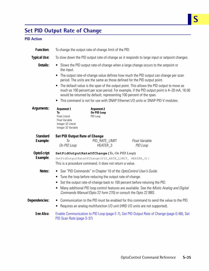
SSet PID Output Rate of ChangePID Action
Function: To change the output rate-of-change limit of the PID.
Typical Use: To slow down the PID output rate-of-change as it responds to large input or setpoint changes.
Details: • Slows the PID output rate-of-change when a large change occurs to the setpoint or the input.
• The output rate-of-change value defines how much the PID output can change per scan period. The units are the same as those defined for the PID output point.
• The default value is the span of the output point. This allows the PID output to move as much as 100 percent per scan period. For example, if the PID output point is 4–20 mA, 16.00 would be returned by default, representing 100 percent of the span.
• This command is not for use with SNAP Ethernet I/O units or SNAP-PID-V modules.
Arguments:
StandardExample:
Set PID Output Rate of ChangeTo PID_RATE_LIMIT Float Variable
On PID Loop HEATER_3 PID Loop
OptoScriptExample:
SetPidOutputRateOfChange(To, On PID Loop)SetPidOutputRateOfChange(PID_RATE_LIMIT, HEATER_3);
This is a procedure command; it does not return a value.
Notes: • See “PID Commands” in Chapter 10 of the OptoControl User’s Guide.• Tune the loop before reducing the output rate-of-change.• Set the output rate-of-change back to 100 percent before retuning the PID.• Many additional PID loop control features are available. See the Mistic Analog and Digital
Commands Manual (Opto 22 form 270) or consult the Opto 22 BBS.
Dependencies: • Communication to the PID must be enabled for this command to send the value to the PID.• Requires an analog multifunction I/O unit (HRD I/O units are not supported).
See Also: Enable Communication to PID Loop (page E-7), Get PID Output Rate of Change (page G-88), Set PID Scan Rate (page S-37)
Argument 1ToFloat LiteralFloat VariableInteger 32 LiteralInteger 32 Variable
Argument 2On PID LoopPID Loop
OptoControl Command Reference S-35
Set PID P TermPID Action
Function: To change the gain value of the PID.
Typical Use: To tune the PID for more or less aggressive performance.
Details: • Gain is the inverse of “proportional band,” a term used in many PID applications.• Gain is used to determine the amount of PID output response to a change in PID input or
PID setpoint.• Always use a non-zero gain value.• Gain has a direct multiplying effect on the integral and derivative values.• Use a negative gain to reverse the direction of the PID output
(typical for cooling applications).• Too much gain results in excessive amounts of PID output change.• Too little gain results in long lasting errors between the PID input and the PID setpoint.• This command is not for use with SNAP Ethernet I/O units or SNAP-PID-V modules.
Arguments:
StandardExample:
Set PID P TermTo GAIN Float Variable
On PID Loop HEATER_3 PID Loop
OptoScriptExample:
SetPidPTerm(To, On PID Loop)SetPidPTerm(GAIN, HEATER_3);
This is a procedure command; it does not return a value.
Notes: • See “PID Commands” in Chapter 10 of the OptoControl User’s Guide.• Use an initial value of 1.0 or -1.0 until a better value is determined.• Typical gain values range from 1 to 40 and -1 to -40.• Use more gain to improve response to step changes.• Use less gain to improve stability.
Dependencies: • Communication to the PID must be enabled for this command to send the value to the PID.• Requires an analog multifunction I/O unit (HRD I/O units are not supported).
See Also: Enable Communication to PID Loop (page E-7)
Argument 1ToFloat LiteralFloat VariableInteger 32 LiteralInteger 32 Variable
Argument 2On PID LoopPID Loop
S-36 OptoControl Command Reference

SSet PID Scan RatePID Action
Function: To change the scan rate (update period) for a PID calculation.
Typical Use: To adapt a PID to the characteristics of the closed-loop control system under program control.
Details: • This is the most important parameter of all the configurable PID parameters. Note that the loop may be impossible to tune if the scan rate is significantly different from the loop dead time.
• The value to send is in seconds. Values range from 0.1 to 6553.5 seconds in 0.1 second increments. The default is 0.1 seconds.
• This command is useful for adapting a PID to work for either heating or cooling when the heat mode has a different loop dead time than the cool mode.
• This command is not for use with SNAP Ethernet I/O units or SNAP-PID-V modules.
Arguments:
StandardExample:
Set PID Scan RateTo Scan_Rate Float Variable
On PID Loop Heater_3 PID Loop
OptoScriptExample:
SetPidScanRate(To, On PID Loop)SetPidScanRate(Scan_Rate, Heater_3);
This is a procedure command; it does not return a value.
Notes: • See “PID Commands” in Chapter 10 of the OptoControl User’s Guide.• Do not use frequently since this will adversely affect the PID performance.• This command will reinitialize the PID loop.
Dependencies: • Communication to the PID must be enabled for this command to send the value to the PID.• Requires an analog multifunction I/O unit (HRD I/O units are not supported).
See Also: Enable Communication to PID Loop (page E-7)
Argument 1ToFloat LiteralFloat VariableInteger 32 LiteralInteger 32 Variable
Argument 2On PID LoopPID Loop
OptoControl Command Reference S-37

Set PID SetpointPID Action
Function: To change the setpoint value of the PID.
Typical Use: To raise or lower the setpoint or to restore it to its original value.
Details: • The value to send has the same engineering units as the specified PID input.• Values are the same as those for the PID input.• This command is not for use with SNAP Ethernet I/O units or SNAP-PID-V modules.
Arguments:
StandardExample:
Set PID SetpointTo PID_Setpoint_Value Float Variable
PID Loop Heater_3 PID Loop
OptoScriptExample:
SetPidSetpoint(To, On PID Loop)SetPidSetpoint(PID_Setpoint_Value, Heater_3);
This is a procedure command; it does not return a value.
Notes: • See “PID Commands” in Chapter 10 of the OptoControl User’s Guide.• Sending the setpoint value to the PID more than 10 times per second can slow the
performance of event/reactions on the I/O unit.• Send a new setpoint value only when necessary.
Dependencies: • Communication to the PID must be enabled for this command to read the actual value from the PID.
• Requires an analog multifunction I/O unit (HRD I/O units are not supported).
See Also: Enable Communication to PID Loop (page E-7), Set PID Setpoint (page S-38)
Argument 1ToAnalog InputAnalog OutputFloat LiteralFloat VariableInteger 32 LiteralInteger 32 Variable
Argument 2PID LoopPID Loop
S-38 OptoControl Command Reference

SSet PriorityChart Action
Function: To increase the relative percentage of execution time for the chart using this command.
Typical Use: To improve performance of the Interrupt chart or any time-sensitive task.
Details: • The new priority takes effect immediately.• Valid priority settings range from 1 to 255.• The priority can be changed on-the-fly to instantly adjust allocated time to a specific portion
of a chart.• Increasing a chart’s priority will give it more time to execute while giving all other charts less
time to execute.
Arguments:
StandardExample:
Set PriorityTo Priority Integer 32 Variable
OptoScriptExample:
SetPriority(To)SetPriority(Priority);
This is a procedure command; it does not return a value.
Notes: • See “Chart Commands” in Chapter 10 of the OptoControl User’s Guide.• Unless you have a specific timing problem to resolve, there is no benefit to changing the
priority from its default value of 1.• Warning: Setting the priority too high in a chart that runs in a loop will severely limit the
capability of the host task to communicate with OptoControl in Debug mode or with OptoDisplay. It is advisable to use priority values of 5 or less for charts that run continuously.
• Interrupt chart usage: Put in Block 0 to give it increased priority (if needed) when it runs. The suggested value is 50.
• Host task usage: See Set Priority of Host Task.
See Also: Set Priority of Host Task (page S-40)
Argument 1ToFloat LiteralFloat VariableInteger 32 LiteralInteger 32 Variable
OptoControl Command Reference S-39
Set Priority of Host TaskChart Action
Function: To increase the relative percentage of execution time for the host task.
Typical Use: To improve communication performance to anything connected to a host port.
Details: • The new priority takes effect at the next scheduled time in the 32-task queue for the host task.
• Valid priority settings range from 1 to 255.• Increasing the host task priority will give it more time to execute while giving all other charts
less time to execute.• Valid range for the On Port parameter (Argument 2) is 0, 1, 2, 3, 4, 5, or 8, to be used as
follows: 0, 1, 2, or 3 = serial COM ports4 = ARCNET host port5 = ISA bus port for G4LC32ISA and G4LC32ISA-LT controllers8 = Ethernet. Due to the way Ethernet is processed, however, this command has little effect on Ethernet host ports.
Arguments:
StandardExample:
Set Priority of Host TaskTo 5 Integer 32 Literal
On Port 4 Integer 32 Literal
OptoScriptExample:
SetPriorityOfHostTask(To, On Port)SetPriorityOfHostTask(5, 4);
This is a procedure command; it does not return a value.
Notes: • See “Chart Commands” in Chapter 10 of the OptoControl User’s Guide.• Increase the host task priority to 5 to improve communication performance to an HMI.• Warning: Setting the host task priority too high will severely limit the capability of all other
charts. It is advisable to use priority values of 10 or less.
See Also: Set Priority (page S-39)
Argument 1ToFloat LiteralFloat VariableInteger 32 LiteralInteger 32 Variable
Argument 2On PortInteger 32 LiteralInteger 32 Variable
S-40 OptoControl Command Reference

SSet SecondsTime/Date Action
Function: To set the seconds value (0 through 59) in the controller’s real-time clock/calendar.
Typical Use: To set the seconds from an OptoControl program.
Details: • The To parameter (Argument 1) can be an integer or a float, although an integer is preferred.• Time is in 24-hour format. For example, 8 a.m. = 08:00:00, 1 p.m. = 13:00:00, and 11:59:00
p.m. = 23:59:00.• If the desired time to set is 2:35:26 p.m., then the To parameter (Argument 1) should contain
the value 26.• Executing this command would set the seconds value in the controller’s real-time
clock/calendar.• The controller’s real-time clock/calendar will automatically increment the time and date
after they are set.• All erroneous values for seconds are ignored.
Arguments:
StandardExample:
Set SecondsTo SECONDS Integer 32 Variable
OptoScriptExample:
SetSeconds(To)SetSeconds(SECONDS);
This is a procedure command; it does not return a value.
Notes: • Use to change the SECONDS to test program logic. Use an integer variable as a change trigger. Set the trigger variable True after the SECONDS variable has the desired value. When the trigger is True, the program executes this command, then sets the trigger variable False.
• Do not issue this command continuously.
See Also: Get Day (page G-45), Get Day of Week (page G-46), Get Hours (page G-59), Get Minutes (page G-64), Get Month (page G-66), Get Seconds (page G-98), Get Year (page G-105), Set Day of Week (page S-16), Set Hours (page S-21), Set Minutes (page S-23), Set Month (page S-25), Set Day (page S-15) Set Year (page S-49)
Argument 1ToFloat LiteralFloat VariableInteger 32 LiteralInteger 32 Variable
OptoControl Command Reference S-41

Set Simple-64 I/O Unit from MOMO MasksI/O Unit Action
Function: To control multiple digital output points on the same 64-point SNAP Simple I/O unit simultaneously with a single command.
Typical Use: To efficiently control all digital outputs on a 64-point rack with one command.
Details: • This command is 64 times faster than using Turn On or Turn Off 64 times.• Updates the IVALs and XVALs for all digital points. Affects only selected digital output
points. Does not affect digital input points. Does not affect analog points in any position on the rack.
• A point is selected for activation by setting the respective bit in the 64-bit data field of argument 1 (the must-on bit mask) to a value of “1.” A point is selected for deactivation by setting the respective bit in the 64-bit data field of argument 2 (the must-off bit mask) to a value of “1.” Any bits set to a value of 0 in both arguments 1 and 2 will leave those points unaffected.
• The least significant bit corresponds to point zero.• If a specific point is disabled or if the entire I/O unit is disabled, only the internal values
(IVALs) will be written.
Arguments:
StandardExample:
Set Simple-64 I/O Unit from MOMO MasksMust On Mask PUMPS_ON_MASK Integer 64 VariableMust Off Mask 0xB0F240010308A020 Integer 64 Literal
Simple-64 I/O Unit PUMP_CTRL_UNIT SNAP Simple 64The effect of this command is illustrated below:
To save space, the example shows only the first eight points and the last eight points on the rack. For the points shown, points 58, 57, 7, 6, and 1 will be turned on. Points 63, 61, 60, and 5 will be turned off. Other points shown are not changed.
OptoScriptExample:
SetSimple64IoUnitFromMomo(Must-On Mask, Must-Off Mask, Simple-64 I/O Unit)SetSimple64IoUnitFromMomo(PUMPS_ON_MASK, 0xB0F240010308A020i64,
PUMP_CTRL_UNIT);
This is a procedure command; it does not return a value. (Note that Integer 64 literals in OptoScript code take an i64 suffix.
Argument 1Must On MaskInteger 64 LiteralInteger 64 Variable
Argument 2Must Off MaskInteger 64 LiteralInteger 64 Variable
Argument 3Simple-64 I/O UnitSNAP Simple 64
Point Number 63 62 61 60 59 58 57 56 7 6 5 4 3 2 1 0
Must-on Bit Mask
Binary 0 0 0 0 0 1 1 0 1 1 0 0 0 0 1 0
Hex 0 6 C 2
Must-off Bit Mask
Binary 1 0 1 1 0 0 0 0 0 0 1 0 0 0 0 0
Hex B 0 2 0
S-42 OptoControl Command Reference

SNotes: Use Bit Set or Bit Clear to change individual bits in an integer variable.
See Also: Get Simple-64 I/O Unit as Binary Value (page G-100)
Set TimeTime/Date Action
Function: To set the time in the controller’s real-time clock/calendar from a string variable.
Typical Use: To set the time from an OptoControl program.
Details: • The From parameter (Argument 1) can be a constant or string variable, although a string variable is preferred.
• Time is in 24-hour format. For example, 8 a.m. = 08:00:00, 1 p.m. = 13:00:00, and 11:59:00 p.m. = 23:59:00.
• If the desired time to set is 2:35:00 p.m., the From parameter (Argument 1) should contain the string “14:35:00.”
• Executing this command would set the time value in the controller’s real-time clock/calendar.
• The controller’s real-time clock/calendar will automatically increment the time and date after they are set.
• All erroneous time strings are ignored.
Arguments:
StandardExample:
Set TimeFrom TIME_STRING String Variable
OptoScriptExample:
SetTime(To)SetTime(TIME_STRING);
This is a procedure command; it does not return a value.
Notes: • In Debug mode OptoControl always sets the date, time, and day of week to the PC clock at the end of a download.
• To change the time, use an integer variable as a change trigger. Set the trigger variable True after the time string has the desired value. When the trigger is True, the program executes this command, then sets the trigger variable False.
• The controller’s real-time clock/calendar will automatically increment the time and date after they are set.
• Do not issue this command continuously.
See Also: Copy Date to String (DD/MM/YY) (page C-60), Copy Date to String (MM/DD/YY) (page C-61), Copy Time to String (page C-62), Set Date (page S-14).
Argument 1FromString LiteralString Variable
OptoControl Command Reference S-43

Set TPO PercentDigital Point Action
Function: To set the on time of an output point as a percentage.
Typical Use: To vary the net output percentage over time. Commonly used to control heater outputs in a pseudo-analog fashion.
Details: • Sets the percentage of on time for an output configured as a TPO.• Valid range is 0 (always off) to 100 (always on).• A TPO period of 10 seconds and an output of 20 percent will cause the output point to go on
for 2.0 seconds (10 seconds x .20) and off for 8.0 seconds at 10-second intervals.
Arguments:
StandardExample:
Set TPO PercentTo (Percent) New_Output Integer 32 Literal
On Point Heater_Output Time Proportional Output
OptoScriptExample:
SetTpoPercent(To Percent, On Point)SetTpoPercent(New_Output, Heater_Output);
This is a procedure command; it does not return a value.
Notes: • When using the output of a PID to drive a digital TPO, scale the analog output point (for the PID) to 0–100. (This analog point does not have to exist physically, but must be one of the 16 points on the I/O unit.) Use Move to copy the PID analog output value to the digital TPO point periodically.
• At low percentages, the output module’s minimum turn-on and turn-off times may affect the accuracy of control. Check the specifications for the module to be used.
• Setting the value of a digital TPO overrides any prior Turn On or Turn Off command for the digital point.
Dependencies: • A Set TPO Period command must be used at least once before this command to define the time period.
• Applies only to output points configured with the TPO feature on digital multifunction I/O units.
See Also: Set TPO Period (page S-45)
Argument 1To (Percent)Float LiteralFloat VariableInteger 32 LiteralInteger 32 Variable
Argument 2On PointTPO
S-44 OptoControl Command Reference

SSet TPO PeriodDigital Point Action
Function: To set the time proportional output (TPO) period of an output point.
Typical Use: To vary the percentage of on time (duty cycle). Commonly used to control heater outputs in a pseudo-analog fashion.
Details: • Sets the period of a TPO to the specified value.• The period is specified from 0.1 to 429,496.7000 seconds (4.97 days), with a resolution of
100 microseconds.• This command must be used before the Set TPO Percent command.• Not available on SNAP Ethernet brains.
Arguments:
StandardExample:
Set TPO PeriodTo (Seconds) 60.0 Float Literal
On Point Heater_Output Time Proportional Output
OptoScriptExample:
SetTpoPeriod(To Seconds, On Point)setTpoPeriod(60.0, Heater_Output);
This is a procedure command; it does not return a value.
Notes: • The time proportion period specifies only the total time over which the output is varied. Set TPO Percent sets the on and off time within this period. For example, a TPO period of 30 seconds and an output of 25 percent will cause the output point to go on for 7.5 seconds (30 seconds x .25) and off for 22.5 seconds at 30-second intervals.
• Although the minimum TPO period is 0.1 seconds (and the resolution is 100 microseconds), at low percentages the minimum turn-on and turn-off times of the digital output module may be greater. Check the specifications for the module to be used.
• To ensure that the TPO period will always be correct, store this and other changeable I/O unit values in permanent memory at the I/O unit. (You can do so through Debug mode.)
• If the TPO period is not stored in permanent memory at the I/O unit, use this command immediately before Set TPO Percent every time. This ensures that the TPO period will be configured properly if the I/O unit has experienced loss of power. However, do not issue these commands more frequently than necessary, since this can be counterproductive.
Dependencies: Applies only to output points configured with the TPO feature on digital multifunction I/O units.
See Also: Set TPO Percent (page S-44)
Argument 1To (Seconds)Float LiteralFloat VariableInteger 32 LiteralInteger 32 Variable
Argument 2On PointTPO
OptoControl Command Reference S-45

Set Up Timer Target ValueMiscellaneous Action
Function: To set the target value of an up timer.
Typical Use: Used to compare actual elapsed time with a target time for sequential control.
Details: • This command sets the target value but does not start the timer. All up timers automatically start from zero as soon as the strategy begins to run.
• Up timers do not stop timing when they reach their target value. Use the Up Timer Target Time Reached? command to determine if the target time has been reached.
• The target value must be a positive number.
Arguments:
StandardExample:
Set Up Timer Target ValueTarget Value 60.0 Float Literal
Up Timer OVEN_TIMER Up Timer Variable
OptoScriptExample:
SetUpTimerTarget(Target Value, Up Timer)SetUpTimerTarget(60.0, Oven_Timer);
This is a procedure command; it does not return a value.
Notes: • See “Miscellaneous Commands” in Chapter 10 of the OptoControl User’s Guide for more information on timers.
• To set the target value and start the timer in one step, use the Move command to move the target value to the timer. The timer will immediately start from zero. Using the Move command overwrites any target value previously set.
See Also: Start Timer (page S-62), Stop Timer (page S-68), Pause Timer (page P-1), Continue Timer (page C-45), Up Timer Target Time Reached? (page U-1)
Argument 1Target ValueFloat LiteralFloat Variable
Argument 2Up TimerUp Timer Variable
S-46 OptoControl Command Reference
SSet Variable FalseLogical Action
Function: To move a False (0) value into an allowable value.
Typical Use: To clear a variable after it has been used for program logic.
Details: All numeric variables are False by default unless initialized by the user to a non-zero value.
Arguments:
StandardExample:
Set Variable FalseFlag_Hopper_Full Integer 32 Variable
OptoScriptExample:
SetVariableFalse(Variable)SetVariableFalse(Flag_Hopper_Full);
This is a procedure command; it does not return a value.
Notes: • See “Logical Commands” in Chapter 10 of the OptoControl User’s Guide.• Speed Tip: This command is faster than Move for moving a zero to a variable.
See Also: Set Variable True (page S-48)
Argument 1[Value]Float VariableInteger 32 Variable
OptoControl Command Reference S-47

Set Variable TrueLogical Action
Function: To move a True (-1) value into an allowable value.
Typical Use: To set a variable to -1.
Details: All numeric variables are False by default unless initialized to a non-zero value.
Arguments:
StandardExample:
Set Variable TrueFLAG_JOB_DONE Integer 32 Variable
OptoScriptExample:
SetVariableTrue(Variable)SetVariableTrue(FLAG_JOB_DONE);
This is a procedure command; it does not return a value.
Notes: • See “Logical Commands” in Chapter 10 of the OptoControl User’s Guide.• Speed Tip: This command is faster than Move for moving a -1 to a variable.
See Also: Set Variable False (page S-47)
Argument 1[Value]Float VariableInteger 32 Variable
S-48 OptoControl Command Reference

SSet YearTime/Date Action
Function: To set the year value (00 through 99) in the controller’s real-time clock/calendar.
Typical Use: To set the year from an OptoControl program.
Details: • The To parameter (Argument 1) can be an integer or a float, although an integer is preferred.• If the desired year to set is 2000, the To parameter (Argument 1) should contain the value 00.• Executing this command would set the year (00 through 99) in the controller’s real-time
clock/calendar.• The controller’s real-time clock/calendar will automatically increment the time and date
after they are set.• All erroneous month values are ignored.
Arguments:
StandardExample:
Set YearTo YEAR Integer 32 Variable
OptoScriptExample:
SetYear(To)SetYear(YEAR);
This is a procedure command; it does not return a value.
Notes: • In Debug mode OptoControl always sets the date, time, and day of week to the PC clock at the end of a download.
• To change the year, use an integer variable as a change trigger. Set the trigger variable True after the year variable has the desired value. When the trigger is True, the program executes this command, then sets the trigger variable False.
• The controller’s real-time clock/calendar will automatically increment the time and date after they are set.
• Do not issue this command continuously.
See Also: Get Day (page G-45), Get Day of Week (page G-46), Get Hours (page G-59), Get Minutes (page G-64), Get Month (page G-66), Get Seconds (page G-98), Get Year (page G-105), Set Day of Week (page S-16), Set Hours (page S-21), Set Minutes (page S-23), Set Month (page S-25), Set Seconds (page S-41) Set Day (page S-15)
Argument 1ToFloat LiteralFloat VariableInteger 32 LiteralInteger 32 Variable
OptoControl Command Reference S-49

Shift Table ElementsMiscellanous Action
Function: To shift numeric table elements up or down.
Typical Use: To follow items on a conveyor.
Details: • For positive shift counts, entries shift toward the end of the table. For negative shift counts, entries shift toward the beginning (index zero) of the table.
• Entries at the beginning or end of the table are lost when shifted beyond those limits.• Zeros are written to entries left empty by shifting.
Arguments:
StandardExample:
Shift Table ElementsShift Count -5 Integer 32 Literal
Table MY_TABLE Float Table
OptoScriptExample:
ShiftTableElements(Shift Count, Table)ShiftTableElements(-5, MY_TABLE);
This is a procedure command; it does not return a value.
Notes: • Use Move from Table Element before this command to capture values that will be shifted out of the table, if they need to be used.
• Use Move to Table Element (for example) after this command to fill vacated entries, if desired.
See Also: Move Table Element to Table (page M-17), Move from Table Element (page M-12), Move to Table Element (page M-26)
Argument 1Shift CountInteger 32 LiteralInteger 32 Variable
Argument 2TableFloat TableInteger 32 Table
S-50 OptoControl Command Reference

SSineMathematical Action
Function: To derive the sine of an angle.
Typical Use: Trigonometric function for computing triangular height of the angle.
Details: • Calculates the sine of Argument 1 and places the result in Argument 2.• Argument 1 has a range of -infinity to +infinity.• The range of Argument 2 is -1.0 to 1.0, inclusive.• The following are examples of sine calculations:
Radians Degrees Result0.0 0.0 0.0
0.785398 45 0.7071061.570796 90 1.02.356194 135 0.7071063.141592 180 0.03.926991 225 -0.7071064.712388 270 -1.05.497787 315 -0.7071066.283185 360 0.0
Arguments:
StandardExample:
SineOf Radians Float Variable
Put Result in SINE Float Variable
OptoScriptExample:
Sine(Of)SINE = Sine(Radians);
This is a function command; it returns the sine of the angle. The returned value can be consumed by a variable (as in the example shown) or by a control structure, mathematical expression, etc. See Chapter 11 of the OptoControl User’s Guide for more information.
Notes: • See “Mathematical Commands” in Chapter 10 of the OptoControl User’s Guide.• To convert units of degrees to units of radians, divide degrees by 57.29578.• Use Arcsine if the sine is known and the angle is desired.
Queue Errors: 35 = Not a number—result invalid.
See Also: Arccosine (page A-13), Cosine (page C-63), Tangent (page T-4)
Argument 1OfAnalog InputAnalog OutputDown Timer VariableFloat LiteralFloat VariableInteger 32 LiteralInteger 32 VariableUp Timer Variable
Argument 2Put Result inAnalog OutputDown Timer VariableFloat VariableInteger 32 VariableUp Timer Variable
OptoControl Command Reference S-51

Square RootMathematical Action
Function: To calculate the square root of a value.
Typical Use: To solve square root calculations.
Details: Takes the square root of Argument 1 and places the result in Argument 2.
Arguments:
StandardExample:
Square RootOf 4 Integer 32 Literal
Put Result in TWO Integer 32 Variable
OptoScriptExample:
SquareRoot(Of)TWO = SquareRoot(4);
This is a function command; it returns square root of the value. The returned value can be consumed by a variable (as in the example shown) or by a control structure, mathematical expression, etc. See Chapter 11 of the OptoControl User’s Guide for more information.
Notes: • See “Mathematical Commands” in Chapter 10 of the OptoControl User’s Guide.• Executes faster than raising a number to the 0.5 power.• Taking the square root of a negative value will result in zero.• To convert a differential pressure value representing flow to the proper engineering units,
convert its current value to a number between 0 and 1, take the square root of this number, then convert it to the desired engineering units. For example: A 0–100" flow signal that represents 0–50,000 CFH has a value of 50. 50/100 = 0.5. The square root of 0.5 is 0.7071. 0.7071 times 50,000 = 35355 CFH.
Queue Errors: 33 = Overflow error—result too large.35 = Not a number—result invalid.
See Also: Raise to Power (page R-2)
Argument 1OfAnalog InputAnalog OutputDown Timer VariableFloat LiteralFloat VariableInteger 32 LiteralInteger 32 VariableUp Timer Variable
Argument 2Put Result inAnalog OutputDown Timer VariableFloat VariableInteger 32 VariableUp Timer Variable
S-52 OptoControl Command Reference

SStart ChartChart Action
Function: To request that a stopped chart begin executing at Block 0 or to request that a suspended chart continue executing from the point at which it was suspended.
Typical Use: In the Powerup chart, to start all other charts that need to run. Also used by a main chart to start event-driven charts.
Details: • This command is only a request.• If the chart is stopped and fewer than 32 tasks are running, then this chart will be added to
the 32-task queue and this command will succeed. Otherwise, it has no effect. If the chart is suspended, then the chart is already part of the 32-task queue and this command will continue the chart from the point at which it is suspended.
• Upon success, the chart will start at its next scheduled time in the 32-task queue.
Arguments:
StandardExample:
Start ChartChart CHART_B Chart
Put Status in STATUS Integer 32 Variable
OptoScriptExample:
StartChart(Chart)STATUS = StartChart(CHART_B);
This is a function command; it returns one of the status codes listed below.
Notes: • See “Chart Commands” in Chapter 10 of the OptoControl User’s Guide.• Normally the status does not need to be checked, since the command will succeed in most
cases. If there are any doubt or concerns, check the STATUS variable.• Use Stop Chart to stop the Interrupt chart (if it’s not in use) to free up a task in the 32-task
queue, if desired.
Dependencies: If the chart is stopped, then a task must be available in the 32-task queue.
Status Codes: -1 = success0 = failure
See Also: Continue Chart (page C-44), Stop Chart (page S-63), Start Default Host Task (page S-56)
Argument 1ChartChart
Argument 2Put Status inFloat VariableInteger 32 Variable
OptoControl Command Reference S-53

Start Continuous Square WaveDigital Point Action
Function: To generate a square wave on an output point.
Typical Use: To drive stepper motor controllers, pulse indicator lamps, or horns or counters connected to digital outputs.
Details: • Generates a digital waveform on the specified digital output point. On Time specifies the amount of time in seconds that the point will remain on during each pulse; Off Time specifies the amount of time the point will remain off.
• The minimum On Time and Off Time is 0.001 second with a resolution of 0.0001 second, making the maximum frequency 500 Hertz.
• The maximum On Time and Off Time is 429,496.7000 seconds (4.97 days on, 4.97 days off).• Timing begins with the off state. If a square wave is already running when this command is
used, the new timing will become effective on the next transition (on-to-off or off-to-on).• Not available on SNAP Ethernet brains.
Arguments:
StandardExample:
Start Continuous Square WaveOn Time (Seconds) 0.100 Integer 32 LiteralOff Time (Seconds) 0.500 Integer 32 LiteralOn Point BLINKING_LAMP Digital Output
StandardExample:
StartContinuousSquareWave(On Time (Seconds), Off Time (Seconds), On Point)StartContinuousSquareWave(0.100, 0.500, BLINKING_LAMP);
This is a procedure command; it does not return a value.
Notes: • Once the pulse train has started, the digital I/O unit maintains the waveform indefinitely.• Use only to start or change the square wave.• To stop a currently executing pulse train, use Turn Off.• The minimum on or off time is 0.001 second; however, the digital output module’s minimum
turn-on and turn-off times may be greater. Check the specifications for the module to be used.
Dependencies: Applies only to outputs on digital multifunction I/O units.
See Also: Turn Off (page T-37), Generate N Pulses (page G-4)
Argument 1On Time (Seconds)Float LiteralFloat VariableInteger 32 LiteralInteger 32 Variable
Argument 2Off Time (Seconds)Float LiteralFloat VariableInteger 32 LiteralInteger 32 Variable
Argument 3On PointDigital Output
S-54 OptoControl Command Reference

SStart CounterDigital Point Action
Function: To activate a digital input counter.
Typical Use: Once at the beginning of a program to activate a digital input counter.
Details: • Must be used to activate counter inputs on all I/O units except SNAP Ethernet I/O units. On SNAP Ethernet I/O units, counters start as soon as they are configured. (Start Counter is only used after you have used the command Stop Counter.)
• Does not reset the counter to zero.• Retains any previously accumulated counts.
Arguments:
StandardExample:
Start CounterOn Point BAGGAGE_COUNTER Counter
OptoScriptExample:
StartCounter(On Point)StartCounter(BAGGAGE_COUNTER);
This is a procedure command; it does not return a value.
Notes: • To keep a counter active after a power failure at the I/O unit, use Debug mode to write or “burn” the current I/O unit configuration to EEPROM after the counter is started.
• Use Clear Counter to clear a counter to zero.
Dependencies: Applies only to inputs configured with the counter feature on digital multifunction I/O units.
See Also: Get Counter (page G-44), Get & Clear Counter (page G-14), Stop Counter (page S-65), Clear Counter (page C-25)
Argument 1On PointCounter
OptoControl Command Reference S-55

Start Default Host TaskChart Action
Function: To request that the default host task leave the suspended state and continue executing.
Typical Use: To resume use of the host task protocol on the default host port after the default host task was suspended to allow the port to be used for something else.
Details: • This command is only a request.• If the default host task is suspended, this command will succeed. Otherwise, it has no
effect.• Upon success, the host task will run at its next scheduled time.
Arguments:
StandardExample:
Start Default Host TaskPut Status in STATUS Integer 32 Variable
OptoScriptExample:
StartDefaultHostTask()STATUS = StartDefaultHostTask();
This is a function command; it returns one of the status codes listed below.
Notes: • See “Chart Commands” in Chapter 10 of the OptoControl User’s Guide.• Normally the status does not need to be checked, since the command will succeed in
most cases.• The default host task cannot be stopped, but it can be suspended so the port can be used for
other purposes and protocols. While it is suspended, no debugging can be done unless another host task is running on another port.
Dependencies: A task must be available in the 32-task queue.
Status Codes: -1 = success0 = failure
See Also: Suspend Default Host Task (page S-74), Stop Host Task (page S-66), Start Host Task (ASCII) (page S-57), Start Host Task (Binary) (page S-58)
Argument 1Put Status inFloat VariableInteger 32 Variable
S-56 OptoControl Command Reference

SStart Host Task (ASCII)Chart Action
Function: To request an additional host task on a port other than that of the default host task.
Typical Use: To connect a modem or radio to a host port for remote debugging or for use with the HMI.
Details: • Starts an additional host task that uses ASCII mode rather than binary mode.• This command is only a request.• If the task is stopped or suspended and fewer than 32 tasks are running, this command will
succeed. Otherwise, it has no effect.• Upon success, the host task is put into the 32-task queue and will start at its next scheduled
time.• The host task cannot be suspended; it can only be stopped using Stop Host Task.• For Ethernet or ARCNET communication, you can use either this command or Start Host Task
(Binary).
Arguments:
StandardExample:
Start Host Task (ASCII)On Port 1 Integer 32 Literal
Put Status in STATUS Integer 32 Variable
OptoScriptExample:
StartHostTaskAscii(On Port)STATUS = StartHostTaskAscii(1);
This is a function command; it returns one of the status codes listed below.
Notes: • See “Chart Commands” in Chapter 10 of the OptoControl User’s Guide.• Normally the status does not need to be checked, since the command will succeed in most
cases. If there are any doubts or concerns, check the STATUS variable.• If a PC running OptoControl in Debug mode or a PC running OptoDisplay is connected via
modem or radio, it must also be in ASCII mode.
Dependencies: A task must be available in the 32-task queue.
Status Codes: -1 = success.0 = failure.
See Also: Start Chart (page S-53), Set Priority (page S-39), Stop Host Task (page S-66), , Start Host Task (Binary) (page S-58)
Argument 1On PortInteger 32 LiteralInteger 32 Variable
Argument 2Put Status inFloat VariableInteger 32 Variable
OptoControl Command Reference S-57

Start Host Task (Binary)Chart Action
Function: To request an additional host task on a port other than that of the default host task.
Typical Use: To connect a PC running OptoControl in Debug mode via a serial port while a PC running OptoDisplay is connected via ARCNET.
Details: • Starts an additional host task that uses binary mode rather than ASCII mode.• This command is only a request.• If the task is stopped or suspended and fewer than 32 tasks are running, this command will
succeed. Otherwise, it has no effect.• Upon success, the task is put into the 32-task queue and will start at its next
scheduled time.• This task cannot be suspended; it can only be stopped using Stop Host Task.• For Ethernet or ARCNET communication, you can use either this command or Start Host Task
(ASCII). Ethernet and ARCNET always use binary mode; serial can use either binary or ASCII.
Arguments:
StandardExample:
Start Host Task (Binary)On Port 1 Integer 32 Literal
Put Status in STATUS Integer 32 Variable
OptoScriptExample:
StartHostTaskBinary(On Port)STATUS = StartHostTaskBinary(1);
This is a function command; it returns one of the status codes listed below.
Notes: • See “Chart Commands” in Chapter 10 of the OptoControl User’s Guide.• Normally the status does not need to be checked, since the command will succeed in most
cases. If there are any doubts or concerns, check the STATUS variable.• Debug mode must also be in binary mode.
Dependencies: A task must be available in the 32-task queue.
Status Codes: -1 = success.0 = failure.
See Also: Start Chart (page S-53), Set Priority (page S-39), Stop Host Task (page S-66), , Start Host Task (ASCII) (page S-57)
Argument 1On PortInteger 32 LiteralInteger 32 Variable
Argument 2Put Status inFloat VariableInteger 32 Variable
S-58 OptoControl Command Reference

SStart Off-PulseDigital Point Action
Function: To turn off a digital output for a specified time or to delay turning it on.
Typical Uses: • To serve as an alternative to the Turn On command.• To “reset” another device.
Details: • Same as using Turn Off followed by a delay followed by Turn On, or if the output was off already, same as a delay followed by Turn On.
• After the off time expires, this command leaves the point on.• The time may be specified from 0.0005 to 429,496.7000 seconds (4.97 days), with a
resolution of 100 microseconds.• During the execution of this command, if another Start Off-Pulse is performed, the current
off-pulse is canceled and the new off-pulse is generated.• The output does not have to be configured with a feature to use this command.• Not available on SNAP Ethernet brains.
Arguments:
StandardExample:
Start Off-PulseOff Time (Seconds) RESET_TIME Float LiteralOn Point PUMP_2_STOP Digital Output
OptoScriptExample:
StartOffPulse(Off Time (Seconds), On Point)StartOffPulse(RESET_TIME, PUMP_2_STOP);
This is a procedure command; it does not return a value.
Notes: • A Turn On command may be used to abort an off-pulse before the end of the off time.• The minimum off time is 0.0005 seconds; however, the digital output module’s minimum
turn-on and turn-off times may be greater. Check the specifications for the module to be used.
• Caution: If this command is used more frequently than the specified delay, the output will remain off.
Dependencies: Applies only to outputs on digital multifunction I/O units.
See Also: Start On-Pulse (page S-60), Turn Off (page T-37), Turn On (page T-40)
Argument 1Off Time (Seconds)Float LiteralFloat VariableInteger 32 LiteralInteger 32 Variable
Argument 2On PointDigital Output
OptoControl Command Reference S-59

Start On-PulseDigital Point Action
Function: To turn on a digital output for a specified period or to delay turning it off.
Typical Uses: • As an alternative to the Turn Off command.• To “reset” another device.• To increment a counter.• To latch devices connected to digital outputs that require a minimum pulse duration to latch,
such as motor starters and latching relays.
Details: • Same as using Turn On followed by a delay followed by Turn Off, or if the output was on already, same as a delay followed by Turn Off.
• After the on time expires, this command leaves the point off.• The time may be specified from 0.0005 to 429,496.7000 seconds (4.97 days), with a
resolution of 100 microseconds.• During the execution of this command, if another Start On-Pulse is performed, the current
on-pulse is cancelled and the new On-pulse is generated.• The output does not have to be configured with a feature to use this command.• Not available on SNAP Ethernet brains.
Arguments:
StandardExample:
Start On-PulseOn Time (Seconds) MIN_LATCH_TIME Float Variable
On Point PUMP_2_RUN Digital Output
OptoScriptExample:
StartOnPulse(On Time (Seconds), On Point)StartOnPulse(MIN_LATCH_TIME, PUMP_2_RUN);
This is a procedure command; it does not return a value.
Notes: • A Turn Off command may be used to abort an on-pulse before the end of the on time.• The minimum on time is 0.0005 seconds; however, the digital output module’s minimum
turn-on and turn-off times may be greater. Check the specifications for the module to be used.
• Caution: If this command is used more frequently than the specified delay, the output will remain on.
Dependencies: Applies only to outputs on digital multifunction I/O units.
See Also: Start Off-Pulse (page S-59), Turn Off (page T-37), Turn On (page T-40)
Argument 1On Time (Seconds)Float LiteralFloat VariableInteger 32 LiteralInteger 32 Variable
Argument 2On PointDigital Output
S-60 OptoControl Command Reference

SStart Quadrature CounterDigital Point Action
Function: To activate a digital input quadrature counter.
Typical Use: Once at the beginning of a program to activate a quadrature counter.
Details: • Must be used to activate quadrature counter inputs on all I/O units except SNAP Ethernet I/O units. On SNAP Ethernet I/O units, counters start as soon as they are configured. (Start Quadrature Counter is only used after you have used the command Stop Quadrature Counter.)
• Does not reset the quadrature counter to zero.• Retains any previously accumulated counts.• A quadrature counter occupies two adjacent points. Input module pairs specifically made for
quadrature counting must be used. The first point must be an even point number on the digital multifunction I/O unit. For example, positions 0 and 1, 4 and 5 are valid, but 1 and 2, 3 and 4 are not.
Arguments:
StandardExample:
Start Quadrature CounterOn Point Encoder_1 Quadrature Counter
OptoScriptExample:
StartQuadratureCounter(On Point)StartQuadratureCounter(Encoder_1);
This is a procedure command; it does not return a value.
Notes: • Before using a quadrature counter, you must activate it with the Start Quadrature Counter command or no additional counts will accumulate.
• Use Clear Quadrature Counter to set the counts to zero.
Dependencies: Applies only to input points configured with the quadrature feature on digital multifunction I/O units.
See Also: Get Quadrature Counter (page G-95), Get & Clear Quadrature Counter (page G-21), Clear Quadrature Counter (page C-32), Stop Quadrature Counter (page S-67)
Argument 1On PointQuadrature Counter
OptoControl Command Reference S-61
Start TimerMiscellaneous Action
Function: To start a timer variable.
Typical Use: To measure time elapsed since an event occurred.
Details: • When you use this command, up timer variables start from 0 and count up.• Down timer variables start from their preset value and count down to 0. Since the default
preset value for a down timer is zero, nothing will happen if you start the timer without first using the Set Down Timer Preset Value command.
Arguments:
StandardExample:
Start TimerTimer Oven_Timer Down Timer Variable
OptoScriptExample:
StartTimer(Timer)StartTimer(Oven_Timer);
This is a procedure command; it does not return a value.
Notes: • See “Miscellaneous Commands” in Chapter 10 of the OptoControl User’s Guide for more information on timers.
• To set the target value (for an up timer) or the preset value (for a down timer) and start the timer at the same time, use the Move command.
• Start Timer always starts up timers from zero and down timers from their preset value. To restart a timer from the value where it was paused, use the command Continue Timer instead.
See Also: Continue Timer (page C-45), Stop Timer (page S-68), Pause Timer (page P-1), Set Down Timer Preset Value (page S-19), Set Up Timer Target Value (page S-46)
Argument 1TimerDown Timer VariableUp Timer Variable
S-62 OptoControl Command Reference

SStop ChartChart Action
Function: To stop a specified chart.
Typical Use: To stop another chart or the chart in which the command appears.
Details: • Unconditionally stops any chart that is either running or suspended.• Removes the stopped chart from the 32-task queue, making another task available.• A chart can stop itself or any other chart.• A chart that stops itself will immediately give up the remaining time allocated in its
time slice(s).• Stopping another chart won’t take effect immediately but will take effect at the beginning of
that chart’s scheduled time in the queue.• Charts that are stopped or suspended cannot start or continue themselves (nor can they do
anything else).• Stopped charts cannot be continued; they can only be started again (that is, their execution
will begin again at Block 0, not at the point at which they were stopped).
Arguments:
StandardExample:
Stop ChartChart CHART_B Chart
OptoScriptExample:
StopChart(Chart)StopChart(CHART_B);
This is a procedure command; it does not return a value.
Notes: • See “Chart Commands” in Chapter 10 of the OptoControl User’s Guide.• Use Suspend Chart if you want to continue a chart from where it left off.
See Also: Chart Stopped? (page C-14), Start Chart (page S-53), Suspend Chart (page S-72)
Argument 1ChartChart
OptoControl Command Reference S-63

Stop Chart on ErrorChart Action
Function: To stop the chart that caused the error at the top of the error queue.
Typical Use: To include in an error handler chart that runs with the other charts in a strategy. This chart monitors the error queue and takes appropriate action. Utilizing this command, the error handler chart can stop any chart that causes an error.
Details: • Since OptoControl is a multitasking environment in the controller, an error handler chart cannot stop another chart instantaneously with this command (since the error handler chart itself only executes periodically). The actual time required depends on how many charts are running simultaneously as well as on the priority of each.
• See the Errors Appendix in the OptoControl User’s Guide for a list of errors that may appear in the Error Queue.
Arguments: None.
StandardExample:
Stop Chart on Error
OptoScriptExample:
StopChartOnError()StopChartOnError();
This is a procedure command; it does not return a value.
Notes: • See “Chart Commands” in Chapter 10 of the OptoControl User’s Guide.• To get to each error in the error queue, the top error must be discarded, bringing the next
error to the top. Use Remove Current Error and Point to Next Error to do this.
See Also: Remove Current Error and Point to Next Error (page R-26), Get Error Count (page G-53), Suspend Chart on Error (page S-73)
S-64 OptoControl Command Reference

SStop CounterDigital Point Action
Function: To deactivate a digital input counter.
Typical Use: To inhibit a counter until further notice.
Details: • Deactivates the specified counter.• Stops counting incoming pulses to the digital input point until Start Counter is used.• Does not reset the counter to zero.• Retains any previously accumulated counts.
Arguments:
StandardExample:
Stop CounterOn Point BEAN_COUNTER Counter
OptoScriptExample:
StopCounter(On Point)StopCounter(BEAN_COUNTER);
This is a procedure command; it does not return a value.
Notes: Use Clear Counter to set counts to zero.
Dependencies: Applies only to inputs configured with the counter feature on digital multifunction I/O units.
See Also: Get Counter (page G-44), Get & Clear Counter (page G-14), Start Counter (page S-55), Clear Counter (page C-25)
Argument 1On PointCounter
OptoControl Command Reference S-65
Stop Host TaskChart Action
Function: To stop any additional host task or suspend the default host task.
Typical Use: To temporarily use the default host port to communicate with a non-host protocol device, such as a hand-held terminal.
Details: • The default host task can only be suspended, not stopped, so it will never lose its place in the 32-task queue.
• A non-default host task will be removed from the 32-task queue, making another task available.
• Unconditionally suspends the default host task or stops a non-default host task.• Does not take effect immediately, but takes effect at the beginning of the task’s scheduled
time in the queue.
Arguments:
StandardExample:
Stop Host TaskOn Port 4 Integer 32 Literal
OptoScriptExample:
StopHostTask(On Port)StopHostTask(4);
This is a procedure command; it does not return a value.
Notes: See “Chart Commands” in Chapter 10 of the OptoControl User’s Guide.
See Also: Start Chart (page S-53), Start Default Host Task (page S-56), Start Host Task (ASCII) (page S-57), Start Host Task (Binary) (page S-58)
Argument 1On PortInteger 32 LiteralInteger 32 Variable
S-66 OptoControl Command Reference

SStop Quadrature CounterDigital Point Action
Function: To deactivate a quadrature counter.
Typical Use: To inhibit a quadrature counter until further notice.
Details: • Stops the specified quadrature counter.• Stops counting incoming quadrature pulses until Start Quadrature Counter is used.• Does not reset the quadrature counter to zero.• Retains any previously accumulated counts.• A quadrature counter occupies two adjacent points. Input module pairs specifically made for
quadrature counting must be used. The first point must be an even point number on the digital multifunction I/O unit. For example, positions 0 and 1, 4 and 5 are valid, but 1 and 2, 3 and 4 are not.
Arguments:
StandardExample:
Stop Quadrature CounterOn Point TABLE_POSITION Quadrature Counter
OptoScriptExample:
StopQuadratureCounter(On Point)StopQuadratureCounter(TABLE_POSITION);
This is a procedure command; it does not return a value.
Notes: Use Clear Quadrature Counter to set quadrature counts to zero.
Dependencies: Applies only to input points configured with the quadrature feature on digital multifunction I/O units.
See Also: Get Quadrature Counter (page G-95), Get & Clear Quadrature Counter (page G-21), Clear Quadrature Counter (page C-32), Start Quadrature Counter (page S-61)
Argument 1On PointQuadrature Counter
OptoControl Command Reference S-67

Stop TimerMiscellaneous Action
Function: To stop a timer variable.
Typical Use: To stop timing an event.
Details: • Once an up timer or a down timer has been stopped, it is at zero. If you stop a timer and move the value to a variable, you will always get 0.0.
• To store the timer’s value at the time it was stopped, or to be able to continue a timer, use the command Pause Timer instead.
Arguments:
StandardExample:
Stop TimerTimer OVEN_TIMER Down Timer Variable
OptoScriptExample:
StopTimer(Timer)StopTimer(OVEN_TIMER);
This is a procedure command; it does not return a value.
Notes: See “Miscellaneous Commands” in Chapter 10 of the OptoControl User’s Guide for more information on timers.
See Also: Start Timer (page S-62), Continue Timer (page C-45), Pause Timer (page P-1), Set Down Timer Preset Value (page S-19), Set Up Timer Target Value (page S-46)
Argument 1TimerDown Timer VariableUp Timer Variable
S-68 OptoControl Command Reference

SString Equal?String Condition
Function: To compare two strings for equality.
Typical Use: To check passwords or barcodes for an exact match.
Details: • Determines if strings in Argument 1 and Argument 2 are equal. Examples:Argument 1 Argument 2 Result
“OPTO” “OPTO” True“OPTO” “Opto” False
“22” “22” True“2 2” “22” False
• Evaluates True if both strings are exactly the same, False otherwise.• Only an exact match on all characters (including leading or trailing spaces) will return a True.• This test is case-sensitive. For example, a “T” does not equal a “t.”• Quotes (“”) are used in OptoScript code, but not in standard OptoControl code.• Functionally equivalent to the Test Equal Strings action.• Quotes (“”) are used in OptoScript code, but not in standard OptoControl code.
Arguments:
StandardExample:
Is NEW_ENTRY String VariableString Equal?
To PASSWORD String Variable
OptoScriptExample:
OptoScript doesn’t use a command; the function is built in. Use the == operator. if (NEW_ENTRY == PASSWORD) then
Notes: • See “String Commands” in Chapter 10 of the OptoControl User’s Guide.• The example shown is only one way to use the == operator. For more information on using
comparison operators and strings in OptoScript code, see Chapter 11 of the OptoControl User’s Guide
• Use String Equal to String Table Element? to compare with strings in a table.
See Also: Test Equal Strings (page T-7), String Equal to String Table Element? (page S-70)
Argument 1IsString LiteralString Variable
Argument 2ToString LiteralString Variable
OptoControl Command Reference S-69

String Equal to String Table Element?String Condition
Function: To compare two strings for equality.
Typical Use: To check passwords or barcodes for an exact match with an entry in a string table.
Details: • Determines if one string (Argument 1) is equal to another (a string at index Argument 2 in string table Argument 3). Examples:
String 1 String 2 Result“OPTO” “OPTO” True“OPTO” “Opto” False
“22” “22” True“2 2” “22” False
• Evaluates True if both strings are exactly the same, False otherwise.• Only an exact match on all characters (including leading or trailing spaces) will return a True.• This test is case-sensitive. For example, a “T” does not equal a “t.”• Quotes (“”) are used in OptoScript code, but not in standard OptoControl code.• A valid range for the At Index parameter (Argument 2) is zero to the table length (size).• Functionally equivalent to the Test Equal Strings action.• Quotes (“”) are used in OptoScript code, but not in standard OptoControl code.
Arguments:
StandardExample:
The following example compares a new barcode to a string in a string table. This could be done in a loop to see if the new barcode exists in a table.
Is NEW_BARCODE String Variable with BarcodeString Equal to String Table Element?
At Index Loop_Index Integer 32 VariableOf Table Current_Products String Table
OptoScriptExample:
OptoScript doesn’t use a command; the function is built in. Use the == operator. if (NEW_BARCODE == Current_Products[Loop_Index]) then
Notes: • See “String Commands” in Chapter 10 of the OptoControl User’s Guide.• The example shown is only one way to use the == operator. For more information on using
comparison operators and strings in OptoScript code, see Chapter 11 of the OptoControl User’s Guide
Queue Errors: 32 = Bad table index value—index was negative or greater than or equal to the table size.
See Also: Test Equal Strings (page T-7), String Equal? (page S-69)
Argument 1IsString LiteralString Variable
Argument 2At IndexInteger 32 LiteralInteger 32 Variable
Argument 3Of TableString Table
S-70 OptoControl Command Reference

SSubtractMathematical Action
Function: To find the difference between two numeric values.
Typical Use: To subtract two numbers to get a third number, or to reduce the first number by the amount of the second.
Details: • Subtracts Argument 2 from Argument 1 and places the result in Argument 3.• Argument 3 can be the same as either of the first two arguments (unless they are read-only,
such as analog inputs), or it can be a completely different argument.
Arguments:
StandardExample:
SubtractNum_Widgets_to_Produce Integer 32 Variable
Minus Num_Widgets_Produced Integer 32 VariablePut Result in Num_Widgets_Left_to_Make Integer 32 Variable
OptoScriptExample:
OptoScript doesn’t use a command; the function is built in. Use the – operator. Num_Widgets_Left_to_Make = Num_Widgets_to_Produce – Num_Widgets_Produced;
Notes: • See “Mathematical Commands” in Chapter 10 of the OptoControl User’s Guide.• In OptoScript code, the – operator has many uses. For more information on mathematical
expressions in OptoScript code, see Chapter 11 of the OptoControl User’s Guide.
Queue Errors: 33 = Overflow error—result too large.
See Also: Decrement Variable (page D-1), Add (page A-3)
Argument 1[Value]Analog InputAnalog OutputDown Timer VariableFloat LiteralFloat VariableInteger 32 LiteralInteger 32 VariableInteger 64 LiteralInteger 64 VariableUp Timer Variable
Argument 2MinusAnalog InputAnalog OutputDown Timer VariableFloat LiteralFloat VariableInteger 32 LiteralInteger 32 VariableInteger 64 LiteralInteger 64 VariableUp Timer Variable
Argument 3Put Result inAnalog OutputDown Timer VariableFloat VariableInteger 32 VariableInteger 64 VariableUp Timer Variable
OptoControl Command Reference S-71

Suspend ChartChart Action
Function: To suspend a specified chart.
Typical Use: To suspend another chart or the chart in which the command appears.
Details: • Unconditionally suspends any chart that is running.• Does not remove the suspended chart from the 32-task queue.• A chart can suspend itself or any other chart.• A chart that suspends itself will immediately give up the remaining time allocated in its time
slice(s) and will no longer use a time slice. • Suspending another chart won’t take effect immediately but will take effect at the beginning
of that chart’s scheduled time in the queue.• Charts that are suspended cannot start or continue themselves (nor can they do
anything else).• Suspended charts can be continued from the point at which they were suspended (using
either Start Chart or Continue Chart), or they can be stopped (using Stop Chart).
Arguments:
StandardExample:
Suspend ChartChart CHART_B Chart
Put Status in STATUS Integer 32 Variable
OptoScriptExample:
SuspendChart(Chart)STATUS = SuspendChart(CHART_B);
This is a function command; it returns one of the status codes listed below.
Notes: See “Chart Commands” in Chapter 10 of the OptoControl User’s Guide.
Status Codes: -1 = success.0 = failure.
See Also: Chart Suspended? (page C-15), Start Chart (page S-53), Continue Chart (page C-44)
Argument 1ChartChart
Argument 2Put Status inFloat VariableInteger 32 Variable
S-72 OptoControl Command Reference

SSuspend Chart on ErrorChart Action
Function: To suspend the chart that caused the error at the top of the error queue.
Typical Use: To include in an error handler chart that runs with the other charts in a strategy. This chart monitors the error queue and takes appropriate action. Utilizing this command, the error handler chart can suspend any chart that causes an error.
Details: • Since OptoControl is a multitasking environment in the controller, an error handler chart cannot suspend another chart instantaneously with this command (since the error handler chart itself only executes periodically). The actual time required depends on how many charts are running simultaneously as well as on the priority of each.
• See the Errors Appendix in the OptoControl User’s Guide for a list of errors that may appear in the Error Queue.
Arguments:
StandardExample:
Suspend Chart on ErrorPut Status in STATUS Integer 32 Variable
OptoScriptExample:
SuspendChartOnError()STATUS = SuspendChartOnError();
This is a function command; it returns one of the status codes listed below.
Notes: • See “Chart Commands” in Chapter 10 of the OptoControl User’s Guide.• To get to each error in the error queue, the top error must be discarded, which brings the
next error to the top. Use Remove Current Error and Point to Next Error to do this.
Status Codes: -1 = success0 = failure
See Also: Remove Current Error and Point to Next Error (page R-26), Get Error Count (page G-53), Stop Chart on Error (page S-64)
Argument 1Put Status inFloat VariableInteger 32 Variable
OptoControl Command Reference S-73
Suspend Default Host TaskChart Action
Function: To suspend the default host task.
Typical Use: To temporarily use the default host port to communicate with a non-host protocol device, such as a hand-held terminal.
Details: • Unconditionally suspends the default host task. This does not take effect immediately, but takes effect at the beginning of the task’s scheduled time in the queue.
• The STATUS variable indicates success (-1) or failure (0).• A failure indicates only that the default host task is already suspended.• After this command has executed, the port that the default host task was using will become
available for general use.
Arguments:
StandardExample:
Suspend Default Host TaskPut Status in STATUS Integer 32 Variable
OptoScriptExample:
SuspendDefaultHostTask()STATUS = SuspendDefaultHostTask();
This is a function command; it returns a -1 indicating success or a 0 indicating failure.
Notes: • See “Chart Commands” in Chapter 10 of the OptoControl User’s Guide.• Normally the status does not need to be checked, since the command will succeed in
most cases.• If the port configuration (baud rate, etc.) is changed, be sure to return to the original
configuration before executing the Start Default Host Task command.
See Also: Start Default Host Task (page S-56), Start Host Task (ASCII) (page S-57), Start Host Task (Binary) (page S-58)
Argument 1Put Status inFloat VariableInteger 32 Variable
S-74 OptoControl Command Reference

T
TTable Element Bit ClearLogical ActionFunction: To clear a specific bit (set it to 0) at the specified index in an integer table.
Typical Use: To clear a bit in an integer table that is used as a flag.
Details: Valid range for the bit to clear is 0–31.
Arguments:
StandardExample:
Table Element Bit ClearElement Index 4 Integer 32 Literal
Of Integer Table PUMP_CTRL_BITS Integer 32 TableBit To Clear 15 Integer 32 Literal
OptoScriptExample:
TableElementBitClear(Element Index, Of Integer Table, Bit to Clear)TableElementBitClear(4, PUMP_CTRL_BITS, 15);
This is a procedure command; it does not return a value.
Queue Errors: 32 = Bad table index value—index was negative or greater than the table size.
See Also: Bit Clear (page B-4), Table Element Bit Set (page T-2), Table Element Bit Test (page T-3)
Argument 1Element IndexInteger 32 LiteralInteger 32 Variable
Argument 2Of Integer TableInteger 32 Table
Argument 3Bit To ClearInteger 32 LiteralInteger 32 Variable
OptoControl Command Reference T-1

Table Element Bit SetLogical Action
Function: To set a specific bit (set it to 1) at the specified index in an integer table.
Typical Use: To set a bit in an integer table that is used as a flag.
Details: Valid range for the bit to set is 0–31.
Arguments:
StandardExample:
Table Element Bit SetElement Index 4 Integer 32 Literal
Of Integer Table PUMP_CTRL_BITS Integer 32 TableBit to Set 15 Integer 32 Literal
OptoScriptExample:
TableElementBitSet(Element Index, Of Integer Table, Bit to Set)TableElementBitSet(4, PUMP_CTRL_BITS, 15);
This is a procedure command; it does not return a value.
Queue Errors: 32 = Bad table index value—index was negative or greater than the table size.
See Also: Bit Set (page B-14), Table Element Bit Clear (page T-1), Table Element Bit Test (page T-3)
Argument 1Element IndexInteger 32 LiteralInteger 32 Variable
Argument 2Of Integer TableInteger 32 Table
Argument 3Bit to SetInteger 32 LiteralInteger 32 Variable
T-2 OptoControl Command Reference

TTable Element Bit TestLogical Action
Function: To test a specific bit at the specified index in an integer table to see if it is set or not.
Typical Use: To test a bit in an integer table that is used as a flag.
Details: • A logical True (-1) is returned if the bit is set, otherwise a logical False (0) is returned.• Valid range for the bit to test is 0–31.
Arguments:
StandardExample:
Table Element Bit TestElement Index 4 Integer 32 Literal
Of Integer Table Pump_Ctrl_Bits Integer 32 TableBit to Test 15 Integer 32 Literal
Put Result in RESULT Integer 32 Variable
OptoScriptExample:
TableElementBitTest(Element Index, Of Integer Table, Bit to Test)RESULT = TableElementBitTest(4, Pump_Ctrl_Bits, 15);
This is a function command; it returns the status of the bit, either set (-1) or not set (0). The returned value can be consumed by a variable (as in the example shown) or by a control structure, I/O point, etc. See Chapter 11 of the OptoControl User’s Guide for more information.
Notes: The value returned is the bit status.
Queue Errors: 32 = Bad table index value—index was negative or greater than the table size.
See Also: Table Element Bit Set (page T-2), Table Element Bit Clear (page T-1)
Argument 1Element IndexInteger 32 LiteralInteger 32 Variable
Argument 2Of Integer TableInteger 32 Table
Argument 3Bit to TestInteger 32 LiteralInteger 32 Variable
Argument 4Put Result inDigital OutputFloat VariableInteger 32 VariableLocal Simple Digital Output
OptoControl Command Reference T-3

TangentMathematical Action
Function: To derive the tangent of an angle.
Typical Use: Trigonometric function for computing angular rise.
Details: • Computes the tangent (in radians) of Argument 1 and places the result in Argument 2.• Tangent produces a result ranging from zero to two times pi, or 6.283185.• Range of Argument 1 is -infinity to +infinity.• Range of Argument 2 is from -infinity to +infinity.• Computing a tangent at pi / 2 ± n * pi intervals results in an error 33 (result too large).• Tangent is sin (angle) / cos (angle).
Arguments:
StandardExample:
TangentOf RADIANS Float Variable
Put Result in TANGENT Float Variable
OptoScriptExample:
Tangent(Of)TANGENT = Tangent(RADIANS);
This is a function command; it returns the tangent of the angle. The returned value can be consumed by a control structure (as in the example shown) or by a variable, I/O point, etc. See Chapter 11 of the OptoControl User’s Guide for more information.
Notes: • See “Mathematical Commands” in Chapter 10 of the OptoControl User’s Guide.• To convert units of degrees to units of radians, divide degrees by 57.29578.• Use Arctangent if the tangent is known and the angle is desired.
Queue Errors: 33 = Overflow error—result too large.35 = Not a number—result invalid.
See Also: Arctangent (page A-15), Cosine (page C-63), Sine (page S-51)
Argument 1OfAnalog InputAnalog OutputDown Timer VariableFloat LiteralFloat VariableInteger 32 LiteralInteger 32 VariableUp Timer Variable
Argument 2Put Result inAnalog OutputDown Timer VariableFloat VariableInteger 32 VariableUp Timer Variable
T-4 OptoControl Command Reference

TTest EqualLogical Action
Function: To determine if two values are equal.
Typical Use: To perform logic branching based on whether an argument equals a set value.
Details: • Determines if Argument 1 is equal to Argument 2 and puts result in Argument 3. The result is -1 (True) if both values are the same, 0 (False) otherwise. Examples:
Argument 1 Argument 2 Argument 30 0 -1-1 0 0
255 65280 022.22 22.22 -1
• The result can be sent directly to a digital output if desired.
Arguments:
StandardExample:
Test EqualTOP_LEVEL Integer 32 Variable
With 1000 Integer 32 LiteralPut Result in FLAG_AT_THE_TOP Integer 32 Variable
OptoScriptExample:
For an OptoScript equivalent, see the Equal? command.
Notes: • See “Logical Commands” in Chapter 10 of the OptoControl User’s Guide.
Argument 1[Value]Analog InputAnalog OutputCounterDigital InputDigital OutputDown Timer VariableFloat LiteralFloat VariableFrequencyInteger 32 LiteralInteger 32 VariableInteger 64 LiteralInteger 64 VariableLocal Simple Digital InputLocal Simple Digital OutputOff PulseOff TotalizerOn PulseOn TotalizerPeriodQuadrature CounterUp Timer Variable
Argument 2WithAnalog InputAnalog OutputCounterDigital InputDigital OutputDown Timer VariableFloat LiteralFloat VariableFrequencyInteger 32 LiteralInteger 32 VariableInteger 64 LiteralInteger 64 VariableLocal Simple Digital InputLocal Simple Digital OutputOff PulseOff TotalizerOn PulseOn TotalizerPeriodQuadrature CounterUp Timer Variable
Argument 3Put Result inDigital OutputFloat VariableInteger 32 VariableLocal Simple Digital OutputUp Timer Variable
OptoControl Command Reference T-5

• When working with floats, this command is useful for determining if two numeric values are exactly the same. However, in many cases it may be safer to use Test Greater or Equal or Test Less or Equal instead, since exact matches of non-integer types are rare.
See Also: Test Greater (page T-8), Test Greater or Equal (page T-9), Test Less (page T-10), Test Less or Equal (page T-12), Test Not Equal (page T-13), Test Within Limits (page T-14)
T-6 OptoControl Command Reference

TTest Equal StringsString Action
Function: To compare two strings for equality.
Typical Use: To check passwords or barcodes for an exact match.
Details: • Determines if Argument 1 and Argument 2 are equal and puts result in Argument 3. The result is -1 (True) if both strings are exactly the same, 0 (False) otherwise. Examples:
Argument 1 Argument 2 Argument 3“OPTO” “OPTO” -1“OPTO” “Opto” 0
“22” “22” -1“2 2” “22” 0
• Only an exact match on all characters (including leading or trailing spaces) will return a True.• This test is case-sensitive. For example, a “T” does not equal a “t.”• The result can be sent directly to a digital output if desired.• This action is functionally equivalent to the String Equal? condition.• Quotes (“”) are used in OptoScript code, but not in standard OptoControl code.
Arguments:
StandardExample:
The following example compares a password variable to a string constant. The resulting value in IS_AUTHORIZED could be used at several points in the program to determine if the user has sufficient authorization. Quotes are shown for clarity only; do not use them in standard commands.Test Equal Strings
Compare Password String VariableWith “LISA” String Literal
Put Result in IS_AUTHORIZED Integer 32 VariableThe following example compares a barcode to a string retrieved from a string table. This instruction would be in a loop that retrieves each entry from a string table and compares it.Test Equal Strings
Compare BARCODE String VariableWith BARCODE_FROM_LIST String Variable
Put Result In IS_IN_LIST Integer 32 Variable
OptoScript: For an OptoScript equivalent, see the String Equal? command.
Notes: • See “String Commands” in Chapter 10 of the OptoControl User’s Guide.• Use String Equal to String Table Element? to compare with strings in a table.
See Also: String Equal? (page S-69) String Equal to String Table Element? (page S-70)
Argument 1CompareString LiteralString Variable
Argument 2WithString LiteralString Variable
Argument 3Put Result inDigital OutputFloat VariableInteger 32 VariableLocal Simple Digital Output
OptoControl Command Reference T-7

Test GreaterLogical Action
Function: To determine if one value is greater than another.
Typical Use: To determine if a counter has reached an upper limit or if an analog value is too high.
Details: • Determines if Argument 1 is greater than Argument 2 and puts result in Argument 3. The result is -1 (True) if Argument 1 is greater than Argument 2, 0 (False) otherwise. Examples:
Argument 1 Argument 2 Argument 30 0 0-1 0 0-1 -3 -1
22.221 22.220 -1
• The result can be sent directly to a digital output if desired.
Arguments:
StandardExample:
Test GreaterIs MY_DATA_COUNT Counter
Greater than 1000 Integer 32 LiteralPut Result in FLAG_MY_DATA_IS_DONE Integer 32 Variable
OptoScriptExample:
For an OptoScript equivalent, see the Greater? command.
Notes: • See “Logical Commands” in Chapter 10 of the OptoControl User’s Guide.• Consider using Test Greater or Equal instead.
See Also: Test Equal (page T-5), Test Greater or Equal (page T-9), Test Less (page T-10), Test Less or Equal (page T-12), Test Not Equal (page T-13), Test Within Limits (page T-14)
Argument 1IsAnalog InputAnalog OutputCounterDigital InputDigital OutputDown Timer VariableFloat LiteralFloat VariableFrequencyInteger 32 LiteralInteger 32 VariableInteger 64 LiteralInteger 64 VariableLocal Simple Digital InputLocal Simple Digital OutputOff PulseOff TotalizerOn PulseOn TotalizerPeriodQuadrature CounterUp Timer Variable
Argument 2Greater thanAnalog InputAnalog OutputCounterDigital InputDigital OutputDown Timer VariableFloat LiteralFloat VariableFrequencyInteger 32 LiteralInteger 32 VariableInteger 64 LiteralInteger 64 VariableLocal Simple Digital InputLocal Simple Digital OutputOff PulseOff TotalizerOn PulseOn TotalizerPeriodQuadrature CounterUp Timer Variable
Argument 3Put Result inDigital OutputFloat VariableInteger 32 VariableLocal Simple Digital OutputUp Timer Variable
T-8 OptoControl Command Reference

TTest Greater or EqualLogical Action
Function: To determine if one value is greater than or equal to another.
Typical Use: To determine if an analog value has reached a maximum allowable value.
Details: • Determines if Argument 1 is greater than or equal to Argument 2 and puts result in Argument 3. The result is -1 (True) if Argument 1 is greater than or equal to Argument 2, 0 (False) otherwise. Examples:
Argument 1 Argument 2 Argument 30 0 -11 0 -1
-32768 -32767 022221 2222 -1
• The result can be sent directly to a digital output if desired.
Arguments:
StandardExample:
Test Greater or EqualIs ROOM_TEMP Analog Input
> or = 78.5000 Float LiteralPut Result in FLAG_ROOM_TEMP_OK Integer 32 Variable
OptoScriptExample:
For an OptoScript equivalent, see the Greater Than or Equal? command.
Notes: • See “Logical Commands” in Chapter 10 of the OptoControl User’s Guide.
Argument 1IsAnalog InputAnalog OutputCounterDigital InputDigital OutputDown Timer VariableFloat LiteralFloat VariableFrequencyInteger 32 LiteralInteger 32 VariableInteger 64 LiteralInteger 64 VariableLocal Simple Digital InputLocal Simple Digital OutputOff PulseOff TotalizerOn PulseOn TotalizerPeriodQuadrature CounterUp Timer Variable
Argument 2> or =Analog InputAnalog OutputCounterDigital InputDigital OutputDown Timer VariableFloat LiteralFloat VariableFrequencyInteger 32 LiteralInteger 32 VariableInteger 64 LiteralInteger 64 VariableLocal Simple Digital InputLocal Simple Digital OutputOff PulseOff TotalizerOn PulseOn TotalizerPeriodQuadrature CounterUp Timer Variable
Argument 3Put Result inDigital OutputFloat VariableInteger 32 VariableLocal Simple Digital OutputUp Timer Variable
OptoControl Command Reference T-9

• When using analog values or digital features in this command, be sure to take into consideration the units that the value is read in and adjust the test values accordingly.
See Also: Test Greater (page T-8), Test Equal (page T-5), Test Less (page T-10), Test Less or Equal (page T-12), Test Not Equal (page T-13), Test Within Limits (page T-14)
Test LessLogical Action
Function: To determine if one value is less than another.
Typical Use: To determine if a tank needs to be filled.
Details: • Determines if Argument 1 is less than Argument 2 and puts result in Argument 3. The result is -1 (True) if Argument 1 is less than Argument 2, 0 (False) otherwise. Examples:
Argument 1 Argument 2 Argument 30 0 0-1 0 -1-1 -3 0
22.221 22.220 0
• The result can be sent directly to a digital output if desired.
Arguments:
StandardExample:
Test LessIs TANK_LEVEL Analog Input
Less than FULL_TANK_LEVEL Integer 32 VariablePut Result in FLAG_TANK_FILL_VALVELocal Simple Digital Output
Argument 1IsAnalog InputAnalog OutputCounterDigital InputDigital OutputDown Timer VariableFloat LiteralFloat VariableFrequencyInteger 32 LiteralInteger 32 VariableInteger 64 LiteralInteger 64 VariableLocal Simple Digital InputLocal Simple Digital OutputOff PulseOff TotalizerOn PulseOn TotalizerPeriodQuadrature CounterUp Timer Variable
Argument 2Less thanAnalog InputAnalog OutputCounterDigital InputDigital OutputDown Timer VariableFloat LiteralFloat VariableFrequencyInteger 32 LiteralInteger 32 VariableInteger 64 LiteralInteger 64 VariableLocal Simple Digital InputLocal Simple Digital OutputOff PulseOff TotalizerOn PulseOn TotalizerPeriodQuadrature CounterUp Timer Variable
Argument 3Put Result inDigital OutputFloat VariableInteger 32 VariableLocal Simple Digital OutputUp Timer Variable
T-10 OptoControl Command Reference

TOptoScript
Example:For an OptoScript equivalent, see the Less? command.
Notes: • See “Logical Commands” in Chapter 10 of the OptoControl User’s Guide.• Consider using Test Less or Equal instead.
See Also: Test Greater (page T-8), Test Greater or Equal (page T-9), Test Equal (page T-5), Test Less or Equal (page T-12), Test Not Equal (page T-13), Test Within Limits (page T-14)
OptoControl Command Reference T-11

Test Less or EqualLogical Action
Function: To determine if one value is less than or equal to another.
Typical Use: To determine if a temperature is below or the same as a certain value.
Details: • Determines if Argument 1 is less than or equal to Argument 2 and puts result in Argument 3. The result is -1 (True) if Argument 1 is less than or equal to Argument 2, 0 (False) otherwise. Examples:
Argument 1 Argument 2 Argument 30 0 -1-1 0 -1-1 -3 0
22.221 22.220 0
• The result can be sent directly to a digital output if desired.
Arguments:
StandardExample:
Test Less or EqualIs TEMPERATURE Float Variable
< or = 98.6 Float LiteralPut Result in FLAG_TEMP_OK Integer 32 Variable
OptoScriptExample:
For an OptoScript equivalent, see the Less Than or Equal? command.
Notes: • See “Logical Commands” in Chapter 10 of the OptoControl User’s Guide.
Argument 1IsAnalog InputAnalog OutputCounterDigital InputDigital OutputDown Timer VariableFloat LiteralFloat VariableFrequencyInteger 32 LiteralInteger 32 VariableInteger 64 LiteralInteger 64 VariableLocal Simple Digital InputLocal Simple Digital OutputOff PulseOff TotalizerOn PulseOn TotalizerPeriodQuadrature CounterUp Timer Variable
Argument 2< or =Analog InputAnalog OutputCounterDigital InputDigital OutputDown Timer VariableFloat LiteralFloat VariableFrequencyInteger 32 LiteralInteger 32 VariableInteger 64 LiteralInteger 64 VariableLocal Simple Digital InputLocal Simple Digital OutputOff PulseOff TotalizerOn PulseOn TotalizerPeriodQuadrature CounterUp Timer Variable
Argument 3Put Result inDigital OutputFloat VariableInteger 32 VariableLocal Simple Digital OutputUp Timer Variable
T-12 OptoControl Command Reference

T• When using analog values or digital features in this command, be sure to take into
consideration the units that the value is read in and adjust the test values accordingly.
See Also: Test Greater (page T-8), Test Greater or Equal (page T-9), Test Less (page T-10), Test Equal (page T-5), Test Not Equal (page T-13), Test Within Limits (page T-14)
Test Not EqualLogical Action
Function: To determine if two values are different.
Typical Use: To check a counter.
Details: • Determines if Argument 1 is different from Argument 2 and puts result in Argument 3. The result is -1 (True) if both values are not the same, 0 (False) otherwise. Examples:
Argument 1 Argument 2 Argument 30 0 0-1 0 -1
255 65280 -122.22 22.22 0
• The result can be sent directly to a digital output if desired.
Arguments:
StandardExample:
Test Not EqualIs COUNTER_VALUE Integer 32 Variable
Not Equal to 100 Integer 32 LiteralPut Result in FLAG_NOT_DONE Integer 32 Variable
Argument 1IsAnalog InputAnalog OutputCounterDigital InputDigital OutputDown Timer VariableFloat LiteralFloat VariableFrequencyInteger 32 LiteralInteger 32 VariableInteger 64 LiteralInteger 64 VariableLocal Simple Digital InputLocal Simple Digital OutputOff PulseOff TotalizerOn PulseOn TotalizerPeriodQuadrature CounterUp Timer Variable
Argument 2Not Equal toAnalog InputAnalog OutputCounterDigital InputDigital OutputDown Timer VariableFloat LiteralFloat VariableFrequencyInteger 32 LiteralInteger 32 VariableInteger 64 LiteralInteger 64 VariableLocal Simple Digital InputLocal Simple Digital OutputOff PulseOff TotalizerOn PulseOn TotalizerPeriodQuadrature CounterUp Timer Variable
Argument 3Put Result inDigital OutputFloat VariableInteger 32 VariableLocal Simple Digital OutputUp Timer Variable
OptoControl Command Reference T-13

OptoScriptExample:
For an OptoScript equivalent, see the Not Equal? command.
Notes: See “Logical Commands” in Chapter 10 of the OptoControl User’s Guide.
See Also: Test Greater (page T-8), Test Greater or Equal (page T-9), Test Less (page T-10), Test Less or Equal (page T-12), Test Equal (page T-5), Test Within Limits (page T-14)
Test Within LimitsLogical Action
Function: To determine if a value is greater than or equal to a low limit and less than or equal to a high limit.
Typical Use: To check if a temperature is within an acceptable range.
Details: A logical True (-1) is returned if within limits, otherwise a logical False (0) is returned.
Arguments:
StandardExample:
Test Within LimitsIs CURRENT_TEMP Float Variable>= COLDEST_TEMP Float Variable
And <= HOTTEST_TEMP Float VariablePut Result in RESULT Integer 32 Variable
OptoScriptExample:
For an OptoScript equivalent, see the Within Limits? command.
See Also: Test Greater (page T-8), Test Greater or Equal (page T-9), Test Less (page T-10), Test Less or Equal (page T-12), Test Not Equal (page T-13), Test Equal (page T-5)
Argument 1IsAnalog InputAnalog OutputCounterDown Timer VariableFloat LiteralFloat VariableFrequencyInteger 32 LiteralInteger 32 VariableInteger 64 LiteralInteger 64 VariableOff PulseOn PulsePeriodTPOUp Timer Variable
Argument 2>=Float LiteralFloat VariableInteger 32 LiteralInteger 32 VariableInteger 64 LiteralInteger 64 Variable
Argument 3And <=Float LiteralFloat VariableInteger 32 LiteralInteger 32 VariableInteger 64 LiteralInteger 64 Variable
Argument 4Put Result inFloat VariableInteger 32 Variable
T-14 OptoControl Command Reference

TTimer Expired?Miscellaneous Condition
Function: To determine if the specified timer has reached its target value. For down timers, the target value is zero. For up timers, it is the value set by the command Set Up Timer Target Value.
Typical Use: To determine if it is time to take an appropriate action.
Details: Evaluates True if the specified timer has reached its target value, False otherwise.
Arguments:
StandardExample:
Is EGG_TIMER Down Timer VariableTimer Expired?
OptoScriptExample:
HasTimerExpired(Timer)if (HasTimerExpired(EGG_TIMER)) then
This is a function command; it returns a -1 (True) if the timer has expired, 0 (False) if not. The returned value can be consumed by a control structure (as in the example shown) or by a variable, I/O point, etc. See Chapter 11 of the OptoControl User’s Guide for more information.
Notes: • Although the timer resolution is 1 millisecond, the accuracy of a time period is limited by the number of charts running concurrently as well as by the priorities of the charts.
• See “Miscellaneous Commands” in Chapter 10 of the OptoControl User’s Guide for more information on using timers.
• This command can be used the same as Down Timer Expired? and Up Timer Target Time Reached?
See Also: Set Down Timer Preset Value (page S-19), Set Up Timer Target Value (page S-46), Start Timer (page S-62), Up Timer Target Time Reached? (page U-1), Down Timer Expired? (page D-22)
Argument 1IsDown Timer VariableUp Timer Variable
OptoControl Command Reference T-15

Transmit Character via Serial PortCommunication—Serial Action
Function: To send a single character to a communication port.
Typical Uses: • To send a message to another device one character at a time. • To send a line feed (character 10) to a serial printer.
Details: • Character values sent will be 0–255 (decimal). Only the last eight bits are sent when thevalue is >255.
• A value of 256 will be sent as a zero. A value of 257 will be sent as a 1.• To send an ASCII null, use zero. To send an ASCII zero, use 48.• Ports 0–3 (RS-232 mode only): Turns RTS on and leaves it on. CTS is on by default except for
COM0 of the M4RTU or M4IO. If CTS is off or the timeout is too short (see Configure Port Timeout Delay), one character will be moved to the transmit buffer. When CTS turns on, the character will be sent. Sending more than one character with CTS off will eventually result in a -41 error. If CTS is enabled, the command does not transmit until CTS is raised high.
Arguments:
StandardExample:
Transmit Character via Serial PortFrom 10 Integer 32 Literal
On Port 1 Integer 32 LiteralPut Status in ERROR_CODE Integer 32 Variable
OptoScriptExample:
TransCharViaSerialPort(Character, On Port)ERROR_CODE = TransCharViaSerialPort(10, 1);
This is a function command; it returns one of the status codes listed below.In OptoScript code, you can also use a character literal for Argument 1. For example, you could use TransCharViaSerialPort('a', 1); rather than having to use TransCharViaSerialPort(97, 1); making the code more readable. Unprintable character codes would still require a number, however.
Notes: • See “Communication—Serial Commands” in Chapter 10 of the OptoControl User’s Guide.• Ports 0–3 (RS-232 mode only): Always connect RTS to CTS on COM0 of the M4RTU or M4IO
unless RTS and CTS must be connected to a modem, printer, or other device. Never connect anything to CTS unless it must be used to handshake with another device.
• Use Transmit String via Serial Port instead when there are a lot of characters to send or when using modems that require RTS-CTS handshaking.
• If sending an eight-bit checksum, no need to Bit AND the checksum value with 255.
Argument 1FromFloat LiteralFloat VariableInteger 32 LiteralInteger 32 Variable
Argument 2On PortInteger 32 LiteralInteger 32 Variable
Argument 3Put Status inFloat VariableInteger 32 Variable
T-16 OptoControl Command Reference

T• Use Turn Off RTS After Next Character before this command to automatically lower RTS
after the character is sent. When wiring RS-485 in 2-wire mode, this is necessary in order to be able to receive again after this command. This is also true if using RS-232 and the 2w/4w is inadvertently set to 2w.
• If talking to devices such as radio modems that require a delay between receiving a message and lowering RTS, use Turn Off RTS when necessary. You can also use Turn On RTS before this command.
Dependencies: • Ports 0–3: baud rate, parity, number of data bits, number of stop bits.• Ports 4, 6, and 7: Must use Transmit NewLine via Serial Port to actually send the message.• Ports 8–10: Use either Transmit NewLine via Serial Port or Transmit String via Ethernet to
send the message.
Status Codes: 0 = No error.-40 = Timeout—specified port already in use.-41 = Send timeout—CTS is off or timeout is too short (see Configure Port Timeout Delay). For ports 4 and 7–10, this error indicates the transmit buffer is full.-51 = Invalid port number—use port 0–10.
See Also: Configure Port (page C-41), Turn On RTS (page T-41), Turn Off RTS (page T-38)
Transmit NewLine via Serial PortCommunication—Serial Action
Function: This command has two context-sensitive functions:• Ports 0–3: To send a carriage return (character 13) and a line feed (character 10) to a port.• Ports 4 and 6–10: To send the message in the transmit buffer of the ARCNET port (port 4),
the local port (port 6), or the peer port (port 7). For ports 4 and 7, a carriage return (character 13) is appended to the message sent. For 8–10, no carriage return is appended.
Typical Uses: • To send a carriage return/line feed to a serial printer.• To send anything to ports 4 and 6–10.
Details: • Ports 0–3: Sends two ASCII characters (13 and 10) to the specified port.• Ports 0–3 (RS-232 mode only): Turns RTS on. Turns RTS off when finished. If CTS is not
connected, it is on by default except on COM0 of the M4RTU or M4IO. If CTS is off or the timeout is too short (see Configure Port Timeout Delay), this command will eventually time out and return a -41 error.
• Ports 4, 6, and 7: Must use this command to actually send what was “sent” by any other command. Anything “sent” to one of these ports is held in the transmit buffer of the port until this command is used. An acknowledgment is expected from the destination. For ports 4 and 7, this acknowledgment is an automatic feature of ARCNET. This command will wait up to the port timeout value for the acknowledgment. Retries will also be performed up to
OptoControl Command Reference T-17

the retry limit. If no acknowledgment is received, this command will eventually time out and return a -41 error.
• Ports 4 and 7–10: All communications are 16-bit CRC error checked.• Ports 8–10: This command can be used to send what is in the transmit buffer.• Caution: The message could be sent and acknowledged but discarded by the destination
with no error if a message is already held in its receive buffer.
Arguments:
StandardExample:
Transmit NewLine via Serial PortOn Port 1 Integer 32 Variable
Put Status in ERROR_CODE Integer 32 Variable
OptoScriptExample:
TransNewLineViaSerialPort(On Port)ERROR_CODE = TransNewLineViaSerialPort(1);
This is a function command; it returns one of the status codes listed below.
Notes: • See “Communication—Serial Commands” in Chapter 10 of the OptoControl User’s Guide.• Ports 0–3 (RS-232 mode only): Always connect RTS to CTS on COM0 of the M4RTU or M4IO
unless RTS and CTS must be connected to a modem, printer, or other device. Never connect anything to CTS unless it must be used to handshake with another device.
• Ports 4 and 7: To be sure that a message sent was actually received, configure the destination device to reply with an “ACK” or an empty string immediately after receiving the message. Wait for this “ACK” for a second or so to verify receipt of the message.
Dependencies: • Ports 0–3: baud rate, parity, number of data bits, number of stop bits.• Ports 4 and 7: Must use Set ARCNET Destination Address for port 4 or Set ARCNET Peer
Destination Address for port 7 before using this command.
Status Codes: 0 = No error.-40 = Timeout—specified port already in use.-41 = Send timeout—CTS is off (ports 0–3), timeout is too short (see Configure Port Timeout Delay), or there is no response from peer. For ports 4 and 7, this error indicates the transmit buffer is full.-51 = Invalid port number—use port 0–7.
See Also: Configure Port (page C-41)
Argument 1On PortInteger 32 LiteralInteger 32 Variable
Argument 2Put Status inFloat VariableInteger 32 Variable
T-18 OptoControl Command Reference
TTransmit String via ARCNETCommunication—Network Action
Function: Sends a message to another ARCNET device.
Typical Use: Sending messages and data to other controllers via the peer port.
Details: • If the transmit buffer of the specified port has any characters in it (previously placed there by Transmit Character via Serial Port), they will be sent first, followed by any characters that may be in the string, for a total of 251 characters.
• If the string is empty, the transmit buffer contents will be sent. Transmit NewLine via Serial Port can also be used to send the transmit buffer contents.
• If both the string and the transmit buffer are empty, an empty message will be sent, which is useful as a user-generated “ACK.”
• Consider using a carriage return as a delimiter between data sets or types when appropriate. Sending one long packet is more efficient than sending several short packets.
• The message sent will have a carriage return automatically appended.
Arguments:
StandardExample:
Transmit String via ARCNETFrom XMIT_MSG String Variable
On Port 7 Integer 32 LiteralPut Status in XMIT_STATUS Integer 32 Variable
OptoScriptExample:
TransStringViaArcnet(String, On Port)XMIT_STATUS = TransStringViaArcnet(XMIT_MSG, 7);
This is a function command; it returns one of the status codes listed below.
Notes: • An ARCNET level acknowledgment is expected from the destination. This is an automatic feature of ARCNET. This command will wait up to the port timeout value for the acknowledgment. Retries will also be performed up to the retry limit. If no acknowledgment is received, this command will eventually time out and return a -41 error. CAUTION: The message could be sent and acknowledged at the ARCNET level but discarded by the receiving controller without notification if its receive buffer is full.
• The ARCNET receive buffer can hold four messages of up to 251 characters each. After this message has been completely “received” by the user program, another message will be accepted into the receive buffer. To avoid message loss by the intended receiver, send one message at a time, waiting for a user generated “ACK” from the receiver before sending another message to the same receiver.
• Valid ports are 4 (also called ARCNET port) and 7 (also called peer port), as well as 12–19, which are twisted-pair ARCNET ports.
• Use Configure Port Timeout Delay to change the timeout time.
Argument 1FromString LiteralString Variable
Argument 2On PortInteger 32 LiteralInteger 32 Variable
Argument 3Put Status inFloat VariableInteger 32 Variable
OptoControl Command Reference T-19

• All messages sent via ARCNET are 16-bit CRC error checked.
Status Codes: 0 = No error.-40 = Timeout—specified port already in use.-41 = Send timeout—timeout is too short (use Configure Port Timeout Delay), or there is no response from the receiver, or the transmit buffer is full.-51 = Invalid port number—use 4 or 7.
See Also: Receive String via ARCNET (page R-19), Transmit Character via Serial Port (page T-16)
Transmit String via EthernetCommunication—Network Action
Function: Sends a message to another device via Ethernet.
Typical Use: Sending messages and data to other controllers via Ethernet ports 9 and 10 (peer ports).
Details: • If the transmit buffer of the specified port has any characters in it (previously placed there by Transmit Character via Serial Port), they will be sent first, followed by any characters that may be in the string, for a total of 1500 characters.
• If the string is empty, the transmit buffer contents will be sent.• If both the string and the transmit buffer are empty, the Ethernet packet will not be sent.• Consider using a carriage return as a delimiter between data sets or types when
appropriate. Sending one long packet is more efficient than sending several short packets.• Terminate the message with a carriage return when sending it to another controller.
Arguments:
StandardExample:
Transmit String via EthernetFrom XMIT_MSG String Variable
Via Session SESSION_NUMBER Integer 32 VariableOn Port 9 Integer 32 Literal
Put Status in ETHERNET_STATUS Integer 32 Variable
OptoScriptExample:
TransStringViaEthernet(String, Via Session, On Port)ETHERNET_STATUS = TransStringViaEthernet(XMIT_MSG, SESSION_NUMBER, 9);
This is a function command; it returns one of the status codes listed below.
Notes: • An Ethernet level acknowledgment is expected from the destination. This is an automatic feature of Ethernet. This command will wait up to the port timeout value for the acknowledgment. Retries will also be performed up to the retry limit. If no acknowledgment is received, this command will eventually time out and return a -41 error. CAUTION: The message could be sent and acknowledged at the Ethernet level but never processed by the
Argument 1FromString LiteralString Variable
Argument 2Via SessionInteger 32 LiteralInteger 32 Variable
Argument 3On PortInteger 32 LiteralInteger 32 Variable
Argument 4Put Status inInteger 32 Variable
T-20 OptoControl Command Reference
Tapplication program in the receiving controller. Therefore, the receiving application program should acknowledge receipt of the message.
• The Ethernet receive buffer can hold up to 1,500 characters.• An Ethernet session is a logical link (a virtual dedicated cable) between two nodes. Up to 32
sessions total can be concurrently established on the three logical Ethernet ports—8, 9, and 10. These three ports use the same Ethernet card.Controller Port # Typical Use TCP/IP Port #
8 Host Port 20019 Peer Port 2002
10 Peer Port 2003
• Use Configure Port Timeout Delay to change the timeout time.• All messages sent via Ethernet are 16-bit CRC error checked.
Dependencies: Must first use Open Ethernet Session to establish a session, or Accept Session on TCP Port to accept a session initiated by a peer.
Status Codes: 0 = No error.-40 = Timeout—specified port already in use.-41 = Send timeout—timeout is too short (use Configure Port Timeout Delay), or there is no response from the receiver or the transmit buffer is full.-51 = Invalid port number—use 8, 9, or 10.-70 = No Ethernet card present.-72 = Timeout—Couldn’t open the session.-74 = Session not open.-75 = Invalid session number—Use 0–127.-77 = This controller doesn’t support Ethernet.
See Also: Receive String via Ethernet (page R-20)
OptoControl Command Reference T-21

Transmit String via Serial PortCommunication—Serial Action
Function: To send a message to a communication port.
Typical Uses: • To send data to another device or to send an alarm message to a serial printer.
Details: • If you have any controller except the G4 series, COM0 is set up by default to use CTS. If the CTS signal is not received or the timeout is too short (see Configure Port Timeout Delay), this command will eventually time out and return a -41 error. A partial message may be sent if the timeout is too short. If the CTS signal is not received, however, no message will be sent.
• If you are using ports 0–3 in RS-232 mode, this command turns RTS on, and then turns RTS off when finished. If CTS is enabled, the command does not transmit until CTS is raised high.
Arguments:
StandardExample:
Transmit String via Serial PortFrom Message1 String Variable
On Port 1 Integer 32 LiteralPut Status in Error_Code Integer 32 Variable
OptoScriptExample:
TransStringViaSerialPort(String, On Port)Error_Code = TransStringViaSerialPort(Message1, 1);
This is a function command; it returns one of the status codes listed below.
Notes: • See “Communication—Serial Commands” in Chapter 10 of the OptoControl User’s Guide.• Ports 0–3 (RS-232 mode only): If you are using any controller (except the G4 series) with a
modem, printer, or other device that requires RTS/CTS flow control, make sure RTS and CTS are connected between the controller and the device. Otherwise, connect RTS to CTS on COM0 of the controller. Never connect RTS and CTS to a device unless the device requires RTS/CTS flow control.
• If you are communicating from one Opto 22 controller to another, you can optimize communications by adding a message delimiter before sending the message. First use the Append Character to String command to append a carriage return (character 13) to the message. Then transmit the message using this command. On the other controller, use Receive String via Serial Port to receive the message.
Dependencies: Ports 0–3: baud rate, parity, number of data bits, number of stop bits.
Status Codes: 0 = No error.-40 = Timeout—specified port already in use.-41 = Send timeout—CTS is off or timeout is too short (see Configure Port Timeout Delay).-51 = Invalid port number—use port 0–3.
See Also: Transmit Character via Serial Port (page T-16), Configure Port (page C-41)
Argument 1FromString LiteralString Variable
Argument 2On PortInteger 32 LiteralInteger 32 Variable
Argument 3Put Status inFloat VariableInteger 32 Variable
T-22 OptoControl Command Reference

TTransmit Table via ARCNETCommunication—Network Action
Function: Sends 32 consecutive numeric table values (128 bytes) to another controller.
Typical Use: Efficient method of numeric data transfer from one controller to another.
Details: • If the table does not have 32 consecutive values starting with the specified index, 128 characters are still sent. Nulls are used as fill characters.
• The message sent will have a carriage return automatically appended.
Arguments:
StandardExample:
Transmit Table via ARCNETStart at Index 0 Integer 32 Literal
Of Table PEER_DATA_TABLE Float TableOn Port 7 Integer 32 Literal
Put Status in XMIT_STATUS Integer 32 Variable
OptoScriptExample:
TransTableViaArcnet(Start at Index, Of Table, On Port)XMIT_STATUS = TransTableViaArcnet(0, PEER_DATA_TABLE, 7);
This is a function command; it returns one of the status codes listed below.
Notes: • Use Transmit Character via Serial Port first to add a destination index, table ID, etc. if desired. These values could be sent as fixed length or carriage return delimited.
• An ARCNET level acknowledgment is expected from the destination. This is an automatic feature of ARCNET. This command will wait up to the port timeout value for the acknowledgment. Retries will also be performed up to the retry limit. If no acknowledgment is received, this command will eventually time out and return a -41 error. CAUTION: The message could be sent and acknowledged at the ARCNET level but discarded by the receiving controller without notification if too many messages are already held in its receive buffer.
• The ARCNET receive buffer can hold four messages of up to 251 characters each. After this message has been completely “received” by the user program, another message will be accepted into the receive buffer. To avoid message loss by the intended receiver, send one message at a time waiting for a user-generated “ACK” from the receiver before sending another message to the same receiver.
• Valid ports are 4 (also called ARCNET port) and 7 (also called ARCNET peer port), as well as ports 12–19, which are twisted-pair ARCNET ports.
• All messages sent via ARCNET are 16-bit CRC error checked.
Status Codes: 0 = No error.-40 = Timeout—specified port already in use.
Argument 1Start at IndexInteger 32 LiteralInteger 32 Variable
Argument 2Of TableFloat TableInteger 32 Table
Argument 3On PortInteger 32 LiteralInteger 32 Variable
Argument 4Put Status inFloat VariableInteger 32 Variable
OptoControl Command Reference T-23

-41 = Send timeout—timeout is too short (use Configure Port Timeout Delay), or there is no response from the receiver, or the transmit buffer is full.-51 = Invalid port number—use 4 or 7.
Queue Errors: 32 = Bad table index value—index was negative or greater than or equal to the table size.
See Also: Receive Table via ARCNET (page R-23), Transmit String via ARCNET (page T-19)
Transmit Table via EthernetCommunication—Network Action
Function: Sends 32 consecutive numeric table values (128 bytes) to another controller.
Typical Use: Efficient method of numeric data transfer from one controller to another.
Details: If the table does not have 32 consecutive values starting with the specified index, 128 characters are still sent. Nulls are used as fill characters.
Arguments:
StandardExample:
Transmit Table via EthernetStart at Index 0 Integer 32 Literal
Of Table Peer_data_table Float TableVia Session Session_num Integer 32 Variable
On Port 9 Integer 32 LiteralPut Status in Xmit_status Integer 32 Variable
OptoScriptExample:
TransTableViaEthernet(Start at Index, Of Table, Via Session, On Port)Xmit_status = TransTableViaEthernet(0, Peer_data_table, Session_num, 9);
This is a function command; it returns one of the status codes listed below.
Notes: • An Ethernet session is a logical link (a virtual dedicated cable) between two nodes. Up to 32 sessions total can be concurrently established on the three logical Ethernet ports—8, 9, and 10. These three ports use the same Ethernet card.Controller Port# Typical Use TCP/IP Port #
8 Host Port 20019 Peer Port 2002
10 Peer Port 2003
• Use Transmit Character via Serial Port first to send a destination index, table ID, etc. if desired. These values could be sent as fixed length or carriage return delimited.
• An Ethernet level acknowledgment is expected from the destination. This is an automatic feature of Ethernet. This command will wait for the Ethernet TCP/IP acknowledgment. If no acknowledgment is received, this command will eventually time out and return a -41 error. Because of standard TCP/IP settings, this process could take about one minute. CAUTION:
Argument 1Start at IndexInteger 32 LiteralInteger 32 Variable
Argument 2Of TableFloat TableInteger 32 Table
Argument 3Via SessionInteger 32 LiteralInteger 32 Variable
Argument 4On PortInteger 32 LiteralInteger 32 Variable
Argument 5Put Status isFloat VariableInteger 32 Variable
T-24 OptoControl Command Reference
TThe message could be sent and acknowledged at the Ethernet level but never processed by the application program in the receiving controller. Therefore, the receiving application program should acknowledge receipt of the message.
• The Ethernet receive buffer can hold up to 1500 characters.• All messages sent via Ethernet are 16-bit CRC error checked.
Dependencies: Must first use Open Ethernet Session to establish a session, or Accept Session on TCP Port to accept a session initiated by a peer.
Status Codes: 0 = No error.30 = Invalid port number for this session. Port number may be different from the open port, or the receiving end may have closed the session. -40 = Timeout—specified port already in use.-41 = Send timeout—timeout is too short (use Configure Port Timeout Delay), or there is no response from the receiver, or the transmit buffer is full.-51 = Invalid port number—use 8, 9, or 10.-70 = No Ethernet card present.-72 = Timeout—Couldn’t open the session.-74 = Session not open.-75 = Invalid session number—Use 0–127.-77 = This controller doesn’t support Ethernet.
See Also: Receive Table via Ethernet (page R-24), Transmit String via Ethernet (page T-20)
Transmit Table via Serial PortCommunication—Serial Action
Function: Sends 32 numeric table values to a communication port.
Typical Use: To share numeric table data with another controller. To send large amounts of numeric table data efficiently.
Details: • Sends up to 32 table values directly from memory.• If the table does not have at least 32 elements starting from the specified index, zeros will
be sent for the missing elements.• 128 bytes will be sent, four bytes per value. Since the values are sent directly from memory,
it doesn’t matter if the data is integer or float.• Valid table indices range from 0 to the declared table length.• Ports 0–3 (RS-232 mode only): Turns RTS on. Turns RTS off when finished. If CTS is not
connected, it is on by default except on COM0 of the M4RTU or M4IO. If CTS is off or the timeout is too short (see Configure Port Timeout Delay), this command will eventually time out and return a -41 error. No message will be sent if CTS is off. A partial message may be sent if the timeout is too short.
OptoControl Command Reference T-25

Arguments:
StandardExample:
Transmit Table via Serial PortStart at Index INDEX Integer 32 Variable
Of Table My_table Integer 32 TableOn Port 1 Integer 32 Literal
Put Status in Error_Code Integer 32 Variable
OptoScriptExample:
TransTableViaSerialPort(Start at Index, Of Table, On Port)Error_Code = TransTableViaSerialPort(Index, My_table, 1);
This is a function command; it returns one of the status codes listed below.
Notes: • See “Communication—Serial Commands” in Chapter 10 of the OptoControl User’s Guide.• Ports 0–3 (NRS-232 mode only): Always connect RTS to CTS on COM0 of the M4RTU or
M4IO unless RTS and CTS must be connected to a modem, printer, or other device. Never connect anything to CTS unless it must be used to handshake with another device.
• Use Move Analog I/O Unit to Table to read all 16 points of an I/O unit and put the result in a float table.
• Use Receive Table via Serial Port to receive this data in the other controller.• Always send the starting table index before sending the values so that the receiving
controller will know where to put the data. If there is only one block of data that always has the same starting index, there is no need to send the starting index separately.
• If sending both integer and float values, be sure to send a type code first so that the receiving controller will know what type of table to store the values in. If the values are stored in the wrong type of table, their value will be interpreted incorrectly.
• Use error-checked communications or calculate and send a CRC first to ensure the integrity of the 128-byte packet.
Dependencies: Ports 0–3: baud rate, parity, number of data bits, number of stop bits.
Status Codes: 0 = No error.-40 = Timeout—specified port already in use.-41 = Send timeout—CTS is off or timeout is too short (see Configure Port Timeout Delay).-51 = Invalid port number—use port 0, 1, 2, 3, or 6.
See Also: Configure Port (page C-41)
Argument 1Start at IndexInteger 32 LiteralInteger 32 Variable
Argument 2Of TableFloat TableInteger 32 Table
Argument 3On PortInteger 32 LiteralInteger 32 Variable
Argument 4Put Status inFloat VariableInteger 32 Variable
T-26 OptoControl Command Reference

TTransmit/Receive Mistic I/O Hex String with ChecksumCommunication—I/O Action
Function: Sends a binary string with checksum to a local simple I/O unit. Waits for and verifies the response.
Typical Use: Functional testing of local simple I/O units.
Details: • A zero result indicates the message was sent and the reply was received with no errors.• Use Get Nth Character and/or Get Substring to parse the response.
Arguments:
StandardExample:
Transmit/Receive Mistic I/O Hex String with ChecksumFrom IO_Command String Variable
On Port 2 Integer 32 LiteralPut Result in Response String VariablePut Status in RECV_STATUS Integer 32 Variable
OptoScriptExample:
TransReceMisticIoHexStringWithChecksum(Hex String, On Port, Put Result in)RECV_STATUS = TransReceMisticIoHexStringWithChecksum(IO_Command, 2,
Response);
This is a function command; it returns one of the status codes listed below.
Notes: For use with local simple I/O units only.
Status Codes: 0 = No error.-40 = Timeout—specified port already in use.-42 = Timeout—response not received within the allotted time (see Configure Port Timeout Delay).-43 = Too few characters received.-45 = Checksum verification failed.-48 = String too short to hold response.-51 = Invalid port number—use port 0–3.
See Also: Transmit/Receive Mistic I/O Hex String with CRC (page T-28)
Argument 1FromString LiteralString Variable
Argument 2On PortInteger 32 LiteralInteger 32 Variable
Argument 3Put Result inString Variable
Argument 4Put Status inFloat VariableInteger 32 Variable
OptoControl Command Reference T-27

Transmit/Receive Mistic I/O Hex String with CRCCommunication—I/O Action
Function: Aids in sending custom commands using hex to an I/O unit configured for binary CRC mode.
Typical Use: Reading a group of 16 event latches from a multifunction I/O unit.
Details: • This command sends a hex string in mistic I/O format. The string is sent in Argument 1. The Argument 1 string must start with the address field and include everything up to the CRC (DVF) field. Do NOT include the CRC (DVF) field. Example: 000341 sends a powerup clear command to the brain at address 00. For details, see Opto 22 form #270. Look for the command you want to send, and then review the binary example of that command.
• This comand automatically calculates and appends the CRC to the command being transmitted, so you don’t have to include it. The command sends the command string, gets the response, and verifies the CRC. A zero result indicates the response was received and verified.
• Hex is used to make the command string and the response string more readable. Communication to and from the I/O unit is binary CRC.
Arguments:
StandadExample:
Transmit/Receive Mistic I/O Hex String with CRCFrom IO_Command String Variable
On Port 2 Integer 32 LiteralPut Result in Response String VariablePut Status in RECV_STATUS Integer 32 Variable
OptoScriptExample:
TransReceMisticIoHexStringWithCrc(Hex String, On Port, Put Result in)RECV_STATUS = TransReceMisticIoHexStringWithCrc(IO_Command, 2, Response);
This is a function command; it returns one of the status codes listed below.
Notes: • For use only with I/O units in binary CRC mode.• Use Convert Hex String to Number when the response represents a count or bit pattern.
Status Codes: 0 = No error.-40 = Timeout—specified port already in use.-42 = Timeout—response not received within allotted time (see Configure Port Timeout Delay).-43 = Too few characters received.-45 = CRC verification failed.-48 = String too short to hold response.-51 = Invalid port number—use port 0–3.
See Also: Transmit/Receive Mistic I/O Hex String with Checksum (page T-27)
Argument 1FromString LiteralString Variable
Argument 2On PortInteger 32 LiteralInteger 32 Variable
Argument 3Put Result inString Variable
Argument 4Put Status inFloat VariableInteger 32 Variable
T-28 OptoControl Command Reference
TTransmit/Receive OPTOMUX StringCommunication—I/O Action
Function: To communicate as a master with an OPTOMUX device using a communication port.
Typical Use: To communicate with OPTOMUX I/O.
Details: • For use with ports 0–3 only.• Adds a leading “>“ (character 62) to the OPTOMUX message.• Calculates an eight-bit checksum and appends it to the end of the OPTOMUX message as
two hex bytes.• Appends a carriage return (character 13) to the end of the OPTOMUX message.• The OPTOMUX response is expected to start with either an A or an N and is expected to end
with a carriage return.• The two characters preceding the carriage return are expected to be the checksum when
data is returned.• The checksum is calculated and compared with what was sent. If there is a checksum error,
or if “?” was substituted for the checksum characters, a -45 error will be returned. The checksum is not stripped from the message.
• Some valid responses are: N03, AB2EB9.• The string variable length for the OPTOMUX response must be greater than the length of the
longest response expected.• The carriage return in the receive buffer is deleted as the response is moved to the string
variable.• The status is an error code that indicates how successful this command was. A zero
indicates OK; any negative value indicates an error.• If the number of characters in the receive buffer is less than the length of the string variable
and none of the characters is a carriage return, a timeout error (-42) will eventually occur. When this happens, all characters in the receive buffer will be moved to the string variable. If this happens frequently, use Configure Port Timeout Delay to increase the timeout value. See Notes below.
• If the communications port is already in use, this command will wait for it to become available until a port-in-use timeout error (-40) occurs.
• RS-232 mode only: Turns RTS on. Turns RTS off when finished. If CTS is not connected, it is on by default except on COM0 of the M4RTU or M4IO. If CTS is off or the timeout is too short (see Configure Port Timeout Delay), this command will eventually time out and return a -41 error. No message will be sent if CTS is off. A partial message may be sent if the timeout is too short.
Arguments: Argument 1FromString LiteralString Variable
Argument 2On PortInteger 32 LiteralInteger 32 Variable
Argument 3Put Result inString Variable
Argument 4Put Status inFloat VariableInteger 32 Variable
OptoControl Command Reference T-29

StandardExample:
Transmit/Receive OPTOMUX StringFrom Optomux_Command String Variable
On Port 1 Integer 32 LiteralPut Result in Optomux_Response String VariablePut Status in Error_Code Integer 32 Variable
OptoScriptExample:
TransReceOptomuxString(String, On Port, Put Result in)Error_Code = TransReceOptomuxString(Optomux_Command, 1,
Optomux_Response);
This is a function command; it returns one of the status codes listed below.
Notes: • See “Communication—Serial Commands” in Chapter 10 of the OptoControl User’s Guide.• Always use Clear Receive Buffer before using this command each time.• Always use Configure Port Timeout Delay once before using this command . As a minimum,
use the result of this formula: (longest message length / baud rate) * 40. For example, a 24-character message at 9600 baud results in a delay of 0.1 seconds.
• RS-232 mode only: Always connect RTS to CTS on COM0 of the M4RTU or M4IO unless RTS and CTS must be connected to a modem, printer, or other device. Never connect anything to CTS unless it must be used to handshake with another device.
Dependencies: • Baud rate, parity, number of data bits, number of stop bits: Parity must be N; number of data bits must be 8; number of stop bits must be 1.
• Must use OPTOMUX protocol.
Status Codes: 0 = No error.-40 = Timeout—specified port already in use.-41 = Send timeout—CTS is off or timeout is too short (see Configure Port Timeout Delay). For ports 4 and 7, this error indicates the transmit buffer is full.-42 = Timeout—no carriage return found in the receive buffer within allotted time (see Configure Port Timeout Delay).-43 = Too few characters received.-44 = Response not formatted correctly (illegal first character).-45 = CRC or checksum failed.-47 = Received a NAK (this is OK—not an error).-51 = Invalid port number—use port 0–3.
See Also: Configure Port (page C-41)
T-30 OptoControl Command Reference

TTransmit/Receive String via ARCNETCommunication—Network Action
Function: Sends a message, and then waits for the response.
Typical Use: Sending messages and data to other controllers via the peer port where a response is expected before continuing.
Details: • See the Details section for Transmit String via ARCNET and Receive String via ARCNET.• If the response has embedded carriage returns, use Receive String via ARCNET to get each
additional carriage return delimited section.
Arguments:
StandardExample:
Transmit/Receive String via ARCNETFrom XMIT_MSG String Variable
On Port 7 Integer 32 LiteralPut Result in RECV_MSG String VariablePut Status in TR_STATUS Integer 32 Variable
OptoScriptExample:
TransReceStringViaArcnet(String, On Port, Put Result in)TR_STATUS = TransReceStringViaArcnet(XMIT_MSG, 7, RECV_MSG);
This is a function command; it returns one of the status codes listed below.
Notes: • Use Move String, Append String to String, or Append Character to String to build the string to send. Consider using a carriage return as a delimiter between data sets or types when appropriate. Sending one long packet is more efficient than sending several short packets.
• Use Receive String via ARCNET or Receive N Characters via ARCNET in the destination controller followed by Transmit String via ARCNET for the reply.
• See the Notes section for Transmit String via ARCNET and Receive String via ARCNET.
Status Codes: 0 = No error.-40 = Timeout—specified port already in use.-41 = Send timeout—timeout is too short (use Configure Port Timeout Delay), or there is no response from the receiver, or the transmit buffer is full.-42 = Timeout—no carriage return found in the receive buffer with allotted time (see Configure Port Timeout Delay).-45 = CRC verification failed.-51 = Invalid port number—use 4 or 7.
See Also: Receive String via ARCNET (page R-19), Transmit String via ARCNET (page T-19)
Argument 1FromString LiteralString Variable
Argument 2On PortInteger 32 LiteralInteger 32 Variable
Argument 3Put Result inString Variable
Argument 4Put Status inFloat VariableInteger 32 Variable
OptoControl Command Reference T-31

Transmit/Receive String via EthernetCommunication—Network Action
Function: Sends a message, and then waits for the response.
Typical Use: Sending messages and data to other controllers via Ethernet ports 9 and 10 (peer ports) and to MIS systems via Ethernet port 8.
Details: • See the Details section for Transmit String via Ethernet and Receive String via Ethernet.• If the response has embedded carriage returns, use Receive String via Ethernet to get each
additional carriage return delimited section.
Arguments:
StandardExample:
Transmit/Receive String via EthernetFrom XMIT_MSG String Variable
Via Session SESSION_NUMBER Integer 32 VariableOn Port 9 Integer 32 Literal
Put Result in RECV_MSG String VariablePut Status in TR_STATUS Integer 32 Variable
OptoScriptExample:
TransReceStringViaEthernet(String, Via Session, On Port, Put Result in)TR_STATUS = TransReceStringViaEtheret(XMIT_MSG, SESSION_NUMBER, 9,
RECV_MSG);
This is a function command; it returns one of the status codes listed below.
Notes: • An Ethernet session is a logical link (a virtual dedicated cable) between two nodes. Up to 32 sessions total can be concurrently established on the three logical Ethernet ports—8, 9, and 10. These three ports use the same Ethernet card.Controller Port # Typical Use TCP/IP Port #
8 Host Port 20019 Peer Port 2002
10 Peer Port 2003
• Use Move String, Append String to String or Append Character to String to build the string to send. Consider using a carriage return as a delimiter between data sets or types when appropriate. Sending one long packet is more efficient than sending several short packets.
• Use Receive String via Ethernet or Receive N Characters via Ethernet in the destination controller followed by Transmit String via Ethernet for the reply.
• See the Notes section for Transmit String via Ethernet and Receive String via Ethernet.
Dependencies: Must first use Open Ethernet Session to establish a session, or Accept Session on TCP Port to accept a session initiated by a peer.
Status Codes: 0 = No error.-40 = Timeout—specified port already in use.
Argument 1FromString LiteralString Variable
Argument 2Via SessionInteger 32 LiteralInteger 32 Variable
Argument 3On PortInteger 32 LiteralInteger 32 Variable
Argument 4Put Result inString Variable
Argument 5Put Status inInteger 32 Variable
T-32 OptoControl Command Reference

OptoControl Command Reference T-33
T-41 = Send timeout—timeout is too short (see Configure Port Timeout Delay), or there is no response from the receiver, or the transmit buffer is full.-42 = Timeout—response not received within allotted time (see Configure Port Timeout Delay).-48 = String too short to hold response.-51 = Invalid port number—use 8, 9, or 10.-70 = No Ethernet card present.-72 = Timeout—Couldn’t open the session.-74 = Session not open.-75 = Invalid session number—Use 0–127.-77 = This controller doesn’t support Ethernet.
Queue Errors: 32 = Bad table index value—index was negative or greater than or equal to the table size.
See Also: Receive String via Ethernet (page R-20), Transmit String via Ethernet (page T-20)Transmit String via Ethernet, Receive String via Ethernet

Transmit/Receive String via Serial PortCommunication—Serial Action
Function: Sends an ASCII message and gets an ASCII response, using a communication port.
Typical Uses: • To poll for ASCII messages from weigh scales, barcode readers, data entry terminals, and other controllers.
• To send data to other devices where an immediate response is expected.
Details: • For use with ports 0–3 only.• Appends a carriage return (character 13) to the end of the message sent. The response is
expected to end with a carriage return (character 13). The carriage return in the receive buffer is deleted as the response is moved to the string variable.
• The string variable length for the response must be at least two greater than the length of the longest message expected.
• The status is an error code that indicates how successful this command was. A zero indicates OK; any negative value indicates an error.
• If the first set of characters in the receive buffer that is equal to the length of the string variable does not contain a carriage return, these characters will be moved to the string variable without error and all remaining characters in the receive buffer will be discarded.
• If the number of characters in the receive buffer is less than the length of the string variable and none of the characters is a carriage return, a timeout error (-42) will eventually occur. When this happens, all characters in the receive buffer will be moved to the string variable. If this happens frequently, use Configure Port Timeout Delay to increase the timeout value. See Notes below.
• If the communication port is already in use, this command will wait for it to become available until a port-in-use timeout error (-40) occurs. If the receive buffer is empty, no message will be sent and an error -42 will be returned.
• RS-232 mode only: Turns RTS on. Turns RTS off when finished. If CTS is not connected, it is on by default except on COM0 of the M4RTU or M4IO. If CTS is off or the timeout is too short (see Configure Port Timeout Delay), this command will eventually time out and return a -41 error. No message will be sent if CTS is off. A partial message may be sent if the timeout is too short.
• No error checking is performed on any data passed.
Arguments:
StandardExample:
Transmit/Receive String via Serial PortFrom Command String Variable
On Port 1 Integer 32 LiteralPut Result in Response String VariablePut Status in Error_Code Integer 32 Variable
Argument 1FromString LiteralString Variable
Argument 2On PortInteger 32 LiteralInteger 32 Variable
Argument 3Put Result inString Variable
Argument 4Put Status inFloat VariableInteger 32 Variable
T-34 OptoControl Command Reference

TOptoScript
Example:TransReceStringViaSerialPort(String, On Port, Put Result in)Error_Code = TransReceStringViaSerialPort(Command, 1, Response);
This is a function command; it returns one of the status codes listed below.
Notes: • See “Communication—Serial Commands” in Chapter 10 of the OptoControl User’s Guide.• Always use Clear Receive Buffer before using this command each time.• Always use Configure Port Timeout Delay once before using this command . As a minimum,
use the result of this formula: (longest message length / baud rate) * 40. For example, a 24-character message at 9600 baud results in a delay of 0.1 seconds.
• When there are multiple responses terminated by a carriage return and a line feed (character 10), all responses received starting with the second response will have a line feed as the first character in the string variable. To remove it, get the first character of the string variable using Get Nth Character where n=1. If the nth character is equal to 10, use Get Substring with Start At set to 2 and Number Of set greater than or equal to the number of characters expected.
• Do not use this command for binary messages, since they may contain numerous carriage returns at unpredictable locations.
• When using this command to communicate with another controller, use Receive String via Serial Port in the other controller.
• RS-232 mode only: Always connect RTS to CTS on COM0 of the M4RTU or M4IO unless RTS and CTS must be connected to a modem, printer, or other device. Never connect anything to CTS unless it must be used to handshake with another device.
Dependencies: Baud rate, parity, number of data bits, number of stop bits.
Status Codes: 0 = No error.-40 = Timeout—specified port already in use.-41 = Send timeout—CTS is off or timeout is too short (see Configure Port Timeout Delay).-42 = Timeout—no carriage return found in the receive buffer within allotted time (see Configure Port Timeout Delay).-51 = Invalid port number—use port 0–3.
See Also: Transmit String via Serial Port (page T-22), Receive Character via Serial Port (page R-14), Configure Port (page C-41)
OptoControl Command Reference T-35

TruncateMathematical Action
Function: Discards the fractional part of a number without changing the whole part.
Typical Use: In totalizing, to separate the whole part of a number from the fractional part to increase overall accuracy.
Details: Separating the whole part from the fractional part allows significantly greater accuracy on the fractional part since more significant digits are made available for the fractional part to use. This technique is especially useful when the total value is greater than 9999.
Arguments:
StandardExample:
TruncateFlow_Total_Raw Float Variable
Put Result in Flow_Total_Integer Integer 32 Variable
OptoScriptExample:
Truncate(Value)Flow_Total_Integer = Truncate(Flow_Total_Raw);
This is a function command; it returns the whole part of the truncated number.
Notes: Subtracting the resulting integer from the float will remove the whole part from thefractional part.
See Also: Round (page R-29)
Argument 1[Value]Down Timer VariableFloat LiteralFloat VariableUp Timer Variable
Argument 2Put Result inDown Timer VariableFloat VariableInteger 32 VariableInteger 64 VariableUp Timer Variable
T-36 OptoControl Command Reference

TTurn OffDigital Point Action
Function: To turn off a digital output point.
Typical Use: To deactivate devices connected to digital outputs, such as motors, pumps, lights, etc.
Details: • Turns off the specified output.• Discontinues any previously executing pulse, square wave, or TPO command immediately.• The output will remain off until directed otherwise.
Arguments:
StandardExample:
Turn OffThe_Lights Local Simple Digital Output
OptoScriptExample:
TurnOff(Output)TurnOff(The_Lights);
This is a procedure command; it does not return a value.In OptoScript code, you could also assign the output a zero value to turn it off:The_Lights = 0;
Notes: • To cause an output on one I/O unit to assume the state of an input on another I/O unit, use Move in standard commands or an assignment in OptoScript code.
• Use NOT to cause an output on one I/O unit to assume the opposite state of an input on another I/O unit.
• Use event/reactions to cause an output to track an input on the same digital multifunction I/O unit.
• Turning off a digital TPO will forcefully turn off the point. The last TPO percent written can still be read.
• Speed Tip: Use Set Digital I/O Unit from MOMO Masks (with a value of 0) to turn off all 16 outputs at once.
Dependencies: • If the output point or the I/O unit is disabled, no action will occur at the output point (XVAL). The IVAL, however, will be updated.
See Also: Set Digital I/O Unit from MOMO Masks (page S-17), Start On-Pulse (page S-60), Start Off-Pulse (page S-59), Turn On (page T-40)
Argument 1[Value]Digital OutputLocal Simple Digital Output
OptoControl Command Reference T-37

Turn Off RTSCommunication—Serial Action
Function: Lowers the RTS output on the specified serial port.
Typical Use: In half-duplex applications that require flow control, such as radio links.
Details: • Use after Transmit Character via Serial Port to lower RTS.• RTS will automatically turn on the next time a character or string is transmitted.
Arguments:
StandardExample:
Turn Off RTSOn Port 3 Integer 32 Literal
Put Status in COMM_STATUS Integer 32 Variable
OptoScriptExample:
TurnOffRts(On Port)COMM_STATUS = TurnOffRts(3);
This is a function command; it returns one of the status codes listed below.
Notes: No need to use when transmitting strings, since RTS is automatically turned off after the last character is sent.
Status Codes: 0 = Success-51 = Invalid port
See Also: Turn On RTS (page T-41)
Argument 1On PortInteger 32 LiteralInteger 32 Variable
Argument 2Put Status inFloat VariableInteger 32 Variable
T-38 OptoControl Command Reference

TTurn Off RTS After Next CharacterCommunication—Serial Action
Function: To inform the communication hardware that the next character sent will be the last in this message.
Typical Use: To turn off RTS after a complete message is sent.
Details: • For use with ports 0–3 only.• Must use when the last character of a message is sent as a single character and RTS must
be turned off to receive a response (as when using half-duplex radio with RS-232 or 2-wire RS-485/422 communication).
• When messages are sent as a string, RTS turns off automatically after the last character in the string is sent.
Arguments: None.
StandardExample:
Turn Off RTS After Next Character
OptoScriptExample:
TurnOffRtsAfterNextChar()TurnOffRtsAfterNextChar();
This is a procedure command; it does not return a value.
Notes: • See “Communication—Serial Commands” in Chapter 10 of the OptoControl User’s Guide.• Always use this command immediately prior to sending the final character of a message if
you want RTS to turn off.
Dependencies: Must be used prior to a command that sends a single character such as Transmit Character via Serial Port.
OptoControl Command Reference T-39

Turn OnDigital Point Action
Function: To turn on a digital output point.
Typical Use: To activate devices connected to digital outputs, such as motors, pumps, lights, etc.
Details: • Turns on the specified output.• Discontinues any previously executing pulse, square wave, or TPO command immediately.• The output will remain on until directed otherwise.
Arguments:
StandardExample:
Turn OnINLET_VALVE Digital Output
OptoScriptExample:
TurnOn(Output)TurnOn(INLET_VALVE);
This is a procedure command; it does not return a value.In OptoScript code, you could also assign the output any non-zero value to turn it on:INLET_VALVE = -1;
Notes: • To cause an output on one I/O unit to assume the state of an input on another I/O unit, use Move in standard commands or an assignment in OptoScript code.
• Use NOT to cause an output on one I/O unit to assume the opposite state of an input on another I/O unit.
• Use event/reactions to cause an output to track an input on the same digital multifunction I/O unit.
• Turning on a digital TPO will forcefully turn on the point. The last TPO percent written can still be read.
• Speed Tip: Use Set Digital I/O Unit from MOMO Masks (with a value of -1) to turn on all 16 outputs at once.
Dependencies: • If the output point or the I/O unit is disabled, no action will occur at the output point (XVAL). The IVAL, however, will be updated.
See Also: Set Digital I/O Unit from MOMO Masks (page S-17), Start On-Pulse (page S-60), Start Off-Pulse (page S-59), Turn Off (page T-37)
Argument 1[Value]Digital OutputLocal Simple Digital Output
T-40 OptoControl Command Reference

TTurn On RTSCommunication—Serial Action
Function: Raises the RTS output on the specified serial port.
Typical Use: To “warm-up” the radio in half-duplex applications that require flow control.
Details: • Use before Transmit Character via Serial Port or Transmit String via Serial Port to raise the RTS output in advance. This allows the radio transmitter time to turn on before it gets any characters to send.
• RTS will automatically turn off right after using Transmit String via Serial Port.
Arguments:
StandardExample:
Turn On RTSOn Port 3 Integer 32 Literal
Put Status in COMM_STATUS Integer 32 Variable
OptoScriptExample:
TurnOnRts(On Port)COMM_STATUS = TurnOnRts(3);
This is a function command; it returns one of the status codes listed below.
Notes: Use Delay (mSec) immediately after this command to give the radio time to turn on. Twenty to 100 milliseconds is usually enough time.
Status Codes: 0 = Success-51 = Invalid port
See Also: Turn Off RTS (page T-38)
Argument 1On PortInteger 32 LiteralInteger 32 Variable
Argument 2Put Status inFloat VariableInteger 32 Variable
OptoControl Command Reference T-41

T-42 OptoControl Command Reference

U
UUp Timer Target Time Reached?Miscellaneous ConditionFunction: To check if an up timer has reached its target time.
Typical Use: Used to go to the next step in a sequential process.
Details: • Up timers do not stop timing when they reach their target value. • Use the Set Up Timer Target Value command to set the target time.
Arguments:
StandardExample:
Up Timer Target Time Reached?Up Timer OVEN_TIMER Up Timer Variable
OptoScriptExample:
HasUpTimerReachedTargetTime(Up Timer)if (HasUpTimerReachedTargetTime(OVEN_TIMER)) then
This is a function command; it returns a value of true (non-zero) or false (0). The returned value can be consumed by a control structure (as in the example shown) or by a variable, I/O point, etc. See Chapter 11 of the OptoControl User’s Guide for more information.
Notes: See “Miscellaneous Commands” in Chapter 10 of the OptoControl User’s Guide for more information on using timers.
See Also: Start Timer (page S-62), Continue Timer (page C-45), Pause Timer (page P-1), Stop Timer (page S-68), Set Up Timer Target Value (page S-46)
Argument 1Up TimerUp Timer Variable
OptoControl Command Reference U-1

U-2 OptoControl Command Reference

V
VVariable False?Logical ConditionFunction: To determine if the specified variable is zero.
Typical Use: To determine if further processing should take place.
Details: Evaluates True if the specified variable has a value of zero, False otherwise.
Arguments:
StandardExample:
Is Pressure_Difference Integer 32 VariableVariable False?
OptoScriptExample:
IsVariableFalse(Variable)if (IsVariableFalse(Pressure_Difference)) then
This is a function command; it returns a value of true (non-zero) or false (0). The returned value can be consumed by a control structure (as in the example shown) or by a variable, I/O point, etc. See Chapter 11 of the OptoControl User’s Guide for more information.A shorter way to achieve the same result in OptoScript code is to use the following:if (not Pressure_Difference) then
See Also: Variable True? (page V-2)
Argument 1IsFloat VariableInteger 32 VariableInteger 64 Variable
OptoControl Command Reference V-1

Variable True?Logical Condition
Function: To determine if the specified variable is non-zero.
Typical Use: To determine if further processing should take place.
Details: Evaluates True if the specified variable has a non-zero value, False otherwise.
Arguments:
StandardExample:
Is Pressure_Difference Integer 32 VariableVariable True?
OptoScriptExample:
VariableTrue(Variable)if (IsVariableTrue(Pressure_Difference)) then
This is a function command; it returns a value of true (non-zero) or false (0). The returned value can be consumed by a control structure (as in the example shown) or by a variable, I/O point, etc. See Chapter 11 of the OptoControl User’s Guide for more information.A shorter way to achieve the same result in OptoScript code is to use the following:if (Pressure_Difference) then
See Also: Variable False? (page V-1)
Argument 1IsFloat VariableInteger 32 VariableInteger 64 Variable
V-2 OptoControl Command Reference

VVerify Checksum on StringString Action
Function: Checks the validity of a message received via serial port.
Typical Use: Ensuring the integrity of the data in a message prior to using it.
Details: • Checksum type is eight-bit.• The Start Value is also known as the “seed.” It is usually zero.• All characters except the last one are included in the verification.• The last character must be the checksum.
Arguments:
StandardExample:
Verify Checksum on StringStart Value 0 Integer 32 LiteralOn String RESPONSE_MSG String Variable
Put Status In CKSUM_STATUS Integer 32 Variable
OptoScriptExample:
VerifyChecksumOnString(Start Value, On String)CKSUM_STATUS = VerifyChecksumOnString(0, RESPONSE_MSG);
This is a function command; it returns one of the status codes listed below.
Status Codes: 0 = No error.-45 = Checksum verification failed.-49 = String was empty.
See Also: Generate Checksum on String (page G-1)
Argument 1Start ValueInteger 32 LiteralInteger 32 Variable
Argument 2On StringString LiteralString Variable
Argument 3Put Status inInteger 32 Variable
OptoControl Command Reference V-3

Verify Forward CCITT on StringString Action
Function: Checks the validity of a message received via serial port.
Typical Use: Ensuring the integrity of the data in a message prior to using it.
Details: • CRC type is 16-bit forward CCITT.• The Start Value is also known as the “seed.” It is usually zero or -1.• All characters except the last two are included in the verification.• The last two characters must be the CRC.
Arguments:
StandardExample:
Verify Forward CCITT on StringStart Value -1 Integer 32 LiteralOn String RESPONSE_MSG String Variable
Put Status In CRC_STATUS Integer 32 Variable
OptoScriptExample:
VerifyForwardCcittOnString(Start Value, On String)CRC_STATUS = VerifyForwardCcittOnString(-1, RESPONSE_MSG);
This is a function command; it returns one of the status codes listed below.
Status Codes: 0 = No error.-45 = CRC verification failed.-49 = String was empty.
See Also: Verify Reverse CCITT on String (page V-6), Generate Forward CCITT on String (page G-2)
Argument 1Start ValueInteger 32 LiteralInteger 32 Variable
Argument 2On StringString LiteralString Variable
Argument 3Put Status inInteger 32 Variable
V-4 OptoControl Command Reference

VVerify Forward CRC-16 on StringString Action
Function: Checks the validity of a message received via serial port.
Typical Use: Ensuring the integrity of the data in a message prior to using it.
Details: • CRC type is 16-bit forward.• The Start Value is also known as the “seed.” It is usually zero or -1.• All characters except the last two are included in the verification.• The last two characters must be the CRC.
Arguments:
StandardExample:
Verify Forward CRC-16 on StringStart Value -1 Integer 32 LiteralOn String RESPONSE_VSS String Variable
Put Status in CRC_STATUS Integer 32 Variable
OptoScriptExample:
VerifyForwardCrc16OnString(Start Value, On String)CRC_STATUS = VerifyForwardCrc16OnString(-1, RESPONSE_VSS);
This is a function command; it returns one of the status codes listed below.
Status Codes: 0 = No error.-45 = CRC verification failed.-49 = String was empty.
See Also: Verify Reverse CRC-16 on String (page V-7), Generate Forward CRC-16 on String (page G-3)
Argument 1Start ValueInteger 32 LiteralInteger 32 Variable
Argument 2On StringString LiteralString Variable
Argument 3Put Status inInteger 32 Variable
OptoControl Command Reference V-5

Verify Reverse CCITT on StringString Action
Function: Checks the validity of a message received via serial port.
Typical Use: Ensuring the integrity of the data in a message prior to using it.
Details: • CRC type is 16-bit reverse CCITT.• The Start Value is also known as the “seed.” It is usually zero or -1.• All characters except the last two are included in the verification.• The last two characters must be the CRC.
Arguments:
StandardExample:
Verify Reverse CCITT on StringStart Value -1 Integer 32 LiteralOn String RESPONSE_MSG String Variable
Put Status in CRC_STATUS Integer 32 Variable
OptoScriptExample:
VerifyReverseCcittOnString(Start Value, On String)CRC_STATUS = VerifyReverseCcittOnString(-1, RESPONSE_MSG);
This is a function command; it returns one of the status codes listed below.
Status Codes: 0 = No error.-45 = CRC verification failed.-49 = String was empty.
See Also: Verify Forward CCITT on String (page V-4), Generate Reverse CCITT on String (page G-6)
Argument 1Start ValueInteger 32 LiteralInteger 32 Variable
Argument 2On StringString LiteralString Variable
Argument 3Put Status inInteger 32 Variable
V-6 OptoControl Command Reference

VVerify Reverse CRC-16 on StringString Action
Function: Checks the validity of a message received via serial port.
Typical Use: Ensuring the integrity of the data in a message prior to using it.
Details: • CRC type is 16-bit reverse.• The Start Value is also known as the “seed.” It is usually zero or -1.• All characters except the last two are included in the verification.• The last two characters must be the CRC.
Arguments:
StandardExample:
Verify Reverse CRC-16 on StringStart Value -1 Integer 32 LiteralOn String RESPONSE_MSG String Variable
Put Status in CRC_STATUS Integer 32 Variable
OptoScriptExample:
VerifyReverseCrc16OnString(Start Value, On String)CRC_STATUS = VerifyReverseCrc16OnString(-1, RESPONSE_MSG);
This is a function command; it returns one of the status codes listed below.
Status Codes: 0 = No error.-45 = CRC verification failed.-49 = String was empty.
See Also: Verify Forward CRC-16 on String (page V-5), Generate Reverse CRC-16 on Table (32 bit) (page G-8)
Argument 1Start ValueInteger 32 LiteralInteger 32 Variable
Argument 2On StringString LiteralString Variable
Argument 3Put Status inInteger 32 Variable
OptoControl Command Reference V-7

V-8 OptoControl Command Reference

W
WWithin Limits?Logical ConditionFunction: To determine if a value is greater than or equal to a low limit and less than or equal to a high limit.
Typical Use: To check if a temperature is within an acceptable range.
Details: • Determines if Argument 1 is no less than Argument 2 and no greater than Argument 3. Evaluates True if Argument 1 falls between Argument 2 and Argument 3 or equals either value. Evaluates False if Argument 1 is less than Argument 2 or greater than Argument 3. Examples:
Argument 1 Argument 2 Argument 3 Result0.0 0.0 100.0 True
-32768 0.0 100.0 False72.1 68.0 72.0 False-1.0 -45.0 45.0 True
Arguments:
StandardExample:
This example evaluates True if Current_Temp is greater than or equal to Coldest_Temp and less than or equal to Hottest_Temp. It evaluates False otherwise.
Is Current_Temp Float VariableWithin Limits?
>= Coldest_Temp Float VariableAnd <= Hottest_Temp Float Variable
OptoScriptExample:
IsWithinLimits(Value, Low Limit, High Limit)if IsWithinLimits(Current_Temp, Coldest_Temp, Hottest_Temp) then
Argument 1IsAnalog InputAnalog OutputCounterDown Timer VariableFloat LiteralFloat VariableFrequencyInteger 32 LiteralInteger 32 VariableInteger 64 LiteralInteger 64 VariableOff PulseOff TotalizerOn PulseOn TotalizerPeriodTPOUp Timer Variable
Argument 2> =Float LiteralFloat VariableInteger 32 LiteralInteger 32 VariableInteger 64 LiteralInteger 64 Variable
Argument 3And < =Float LiteralFloat VariableInteger 32 LiteralInteger 32 VariableInteger 64 LiteralInteger 64 Variable
OptoControl Command Reference W-1

This is a function command; it returns a value of true (non-zero) or false (0). The returned value can be consumed by a control structure (as in the example shown) or by a variable, I/O point, etc. See Chapter 11 of the OptoControl User’s Guide for more information.
Notes: • See “Logical Commands” in Chapter 10 of the OptoControl User’s Guide.• Use to replace two conditions: Less Than or Equal? and Greater Than or Equal?
See Also: Less Than or Equal? (page L-2) Greater Than or Equal? (page G-107)
W-2 OptoControl Command Reference

WWrite Byte to PC Memory (ISA only)Controller Action
Function: Writes one byte to memory on another card in the PC.
Typical Use: To send eight-bit data to other cards plugged into the PC bus via the assigned memory address for the card.
Details: • When the ISA controller is used in a typical PC, this command must first get permission from the DMA controller in the PC to talk over the bus. This is a relatively slow process.
• When the ISA controller is used in a passive backplane as the bus master, this command is executed immediately.
• The value sent is treated as an unsigned short.
Arguments:
StandardExample:
Write Byte to PC Memory (ISA only)From 0x22 Integer 32 Literal
To Address 0xD0000 Integer 32 LiteralPut Status in Write_Status Integer 32 Variable
OptoScriptExample:
WriteByteToPcMemory(Byte, To Address)Write_Status = WriteByteToPcMemory(0x22, 0xD0000);
This is a function command; it returns one of the status codes listed below.
Notes: • The numeric mode was changed to hex before entering the address of the port in the above example. (D0000 hex = 851968.)
• Memory on the PC motherboard cannot be accessed.• The status returned is the error code. If the DMA channel in the PC wasn’t configured
properly, a bus error may be posted to the error queue, the chart will stop, and the PC may hang.
Dependencies: When the ISA controller is used in a typical PC, one of the unused DMA channels in the PC must be configured for use by the ISA controller. Likewise, the ISA controller must be configured to use the chosen DMA channel. See the ISA controller manual for details.
Status Codes: 0 = No error.-77 = This is not an ISA controller.-78 = Illegal memory address.
Queue Errors: 38 = Bus error—DMA not configured.
See Also: Write Word to PC Memory (ISA only) (page W-12), Write Byte to PC Port (ISA only) (page W-4)
Argument 1FromInteger 32 LiteralInteger 32 Variable
Argument 2To AddressInteger 32 LiteralInteger 32 Variable
Argument 3Put Status inFloat VariableInteger 32 Variable
OptoControl Command Reference W-3

Write Byte to PC Port (ISA only)Controller Action
Function: Writes one byte to a port on another card in the PC.
Typical Use: To send eight-bit data to other cards plugged into the PC bus via the assigned port address for the card.
Details: • When the ISA controller is used in a typical PC, this command must first get permission from the DMA controller in the PC to talk over the bus. This is a relatively slow process.
• When the ISA controller is used in a passive backplane as the bus master, this command executes immediately.
• The value sent is treated as an unsigned short.
Arguments:
StandardExample:
Write Byte to PC Port (ISA only)From 22 Integer 32 Literal
To Address 851968 Integer 32 LiteralPut Status in Write_Status Integer 32 Variable
OptoScriptExample:
WriteByteToPcPort(Byte, To Address)Write_Status = WriteByteToPcPort(22, 851968);
This is a function command; it returns one of the status codes listed below.
Notes: • Utilities Set DMA0, Set DMA5, Set DMA6, and Set DMA7 can be used to set up DMA channels.
• PC port addresses range from 000 to 3FF hex and must be entered in decimal.• The status returned is the error code. If the DMA channel in the PC wasn’t configured
properly, a bus error may be posted to the error queue, the chart will stop, and the PC may hang.
Dependencies: When the ISA controller is used in a typical PC, one of the unused DMA channels in the PC must be configured for use by the ISA controller. Likewise, the ISA controller must be configured to use the chosen DMA channel. See the ISA controller manual for details.
Status Codes: 0 = No error.-77 = This is not an ISA controller.-78 = Illegal memory address.
Queue Errors: 38 = Bus error—DMA not configured.
See Also: Write Word to PC Port (ISA only) (page W-13), Write Byte to PC Memory (ISA only) (page W-3)
Argument 1FromInteger 32 LiteralInteger 32 Variable
Argument 2To AddressInteger 32 LiteralInteger 32 Variable
Argument 3Put Status inFloat VariableInteger 32 Variable
W-4 OptoControl Command Reference

WWrite I/O Unit Configuration to EEPROMI/O Unit Action
Function: Stores all channel parameters, watchdog settings, PID parameters, and event/reactions to EEPROM at the I/O unit.
Typical Use: Allows the I/O unit to be fully functional at powerup. No further configuration by a controller is needed.
Details: This command takes about one second to complete. During this time, no other communication to the I/O unit port is permitted. It should only be used where it will execute just once each time the program runs—typically in the Powerup chart after all special configuration commands are sent to the I/O unit.
Arguments:
StandardExample:
Write I/O Unit Configuration to EEPROMOn I/O Unit FURNACE_PID G4 Analog Multifunction I/O Unit
OptoScriptExample:
WriteIoUnitConfigToEeprom(On I/O Unit)WriteIoUnitConfigToEeprom(FURNACE_PID);
This is a procedure command; it does not return a value.
Argument 1On I/O UnitB100 Digital Multifunction I/O UnitB200 Analog Multifunction I/O UnitB3000 SNAP AnalogB3000 SNAP DigitalB3000 SNAP Mixed I/OG4 Analog Multifunction I/O UnitG4 Digital Local Simple I/O UnitG4 Digital Multifunction I/O UnitG4 Digital Remote Simple I/O UnitHRD Analog Current Output I/O UnitHRD Analog RTD Input I/O UnitHRD Analog Thermocouple/mV Input I/O UnitHRD Analog Voltage Output I/O UnitHRD Analog Voltage/Current Input I/O UnitSNAP Digital 64SNAP Remote Simple Digital
OptoControl Command Reference W-5

Write Numeric Table to I/O Memory MapCommunication—I/O Action
Function: Write a range of values from an integer 32 or float table into an Opto 22 SNAP Ethernet I/O memory map address.
Typical Use: To access areas of the memory map not directly supported by OptoControl.
Details: • This command works with SNAP Ethernet I/O units that have been configured in OptoControl. The controller must be connected to the I/O unit for this command to work.
• Argument 1, Length, is the number of table elements and also the length of data in the memory map in quads (groups of four bytes).
• Argument 4, Mem address, includes only the last eight digits of the memory map address (the lower 32 bits).
Arguments:
StandardExample:
Write Numeric Table to I/O Memory MapLength 0x10 Integer 32 Literal
Start Index 0x5 Integer 32 LiteralI/O Unit MYIOUNIT B3000 SNAP Mixed I/O
Mem Address 0xFFFFFFFF Integer 32 LiteralFrom MYINTTABLE Integer 32 Table
Put Status in STATUS Integer 32 Variable
OptoScriptExample:
WriteNumTableToIoMemMap(Length, Start Index, I/O Unit, Mem Address, Table)STATUS = WriteNumTableToIoMemMap(0x10, 0x5, MYIOUNIT, OxFFFFFFFF,
MYINTTABLE);
This is a function command; it returns one of the status codes listed below. In OptoScript, you can use hex in one argument while not using it in others, for example:STATUS = WriteNumTableToIoMemMap(16, 5, MYIOUNIT, OxFFFFFFFF, MYINTTABLE);
Notes: • Use hex integer display for easy entering of memory map addresses. When you display integers in hex, note that the length of data and start index arguments are also in hex.
• The controller does not convert the table type to match the area of the memory map being written to. The controller has no knowledge of which memory map areas are integers and which are floats. You must write the correct type of data to the specified memory map address.
Argument 1LengthInteger 32 LiteralInteger 32 Variable
Argument 2Start IndexInteger 32 LiteralInteger 32 Variable
Argument 3I/O UnitB3000 SNAP Mixed I/OSNAP Digital 64
Argument 4Mem AddressInteger 32 LiteralInteger 32 Variable
Argument 5FromFloat TableInteger 32 Table
Argument 6Put Status inInteger 32 Variable
W-6 OptoControl Command Reference

WFor example, unpredictable results would occur if you try to write an integer 32 table to the analog bank area of the memory map. A float table should be used instead. See the SNAP Ethernet-Based I/O Units Programming & Protocols Guide (Opto 22 form 1465) to determine the data types for specific areas of the memory map.
Status Codes: 0 = Success-32 = Bad table index value—index was negative or greater than the table size.-47 = Received a NAK from the I/O unit.-74 = Session not open.
See Also: Read Numeric Variable from I/O Memory Map (page R-8), Read Numeric Table from I/O Memory Map (page R-6), Write Numeric Variable to I/O Memory Map (page W-8)
OptoControl Command Reference W-7

Write Numeric Variable to I/O Memory MapCommunication—I/O Action
Function: Write a value from an integer 32 or float variable into an Opto 22 SNAP Ethernet I/O memory map address.
Typical Use: To access areas of the memory map not directly supported by OptoControl.
Details: This command works with SNAP Ethernet I/O units that have been configured in OptoControl. The controller must be connected to the I/O unit for this command to work.
Arguments:
StandardExample:
Write Numeric Variable to I/O Memory MapI/O Unit MYIOUNIT B3000 SNAP Mixed I/O
Mem Address 0xFFFFFFFF Integer 32 LiteralFrom MYINTVAR Integer 32 Variable
Put Status in STATUS Integer 32 Variable
OptoScriptExample:
WriteNumVarToIoMemMap(I/O Unit, Mem Address, Variable)STATUS = WriteNumVarToIoMemMap(MYIOUNIT, OxFFFFFFFF, MYINTVAR);
This is a function command; it returns one of the status codes listed below.
Notes: • Use hex integer display in OptoControl for easy entering of memory map addresses. If you copy a memory map address from the SNAP Ethernet brain’s built-in Web pages, be sure you delete any spaces within the address.
• The controller does not convert the variable type to match the area of memory map being written to. The controller has no knowledge of which memory map areas are integers and which are floats. You must write the correct type of data to the specified memory map address.
For example, if you are using the SNAP PID module (SNAP-PID-V), use an integer to write the setpoint, which is in counts, and use a float to write the analog output.
As another example, unpredictable results would occur if you try to write an integer 32 variable to the analog point area of the memory map. Use a float variable instead.
See the SNAP Ethernet-Based I/O Units Programming & Protocols Guide (Opto 22 form 1465) to determine the data types for specific areas of the memory map.
Status Codes: 0 = Success-47 = Received a NAK from the I/O unit.-74 = Session not open.
See Also: Read Numeric Variable from I/O Memory Map (page R-8), Read Numeric Table from I/O Memory Map (page R-6), Write Numeric Table to I/O Memory Map (page W-6)
Argument 1I/O UnitB3000 SNAP Mixed I/OSNAP Digital 64
Argument 2Mem AddressInteger 32 LiteralInteger 32 Variable
Argument 3FromFloat VariableInteger 32 Variable
Argument 4Put Status inInteger 32 Variable
W-8 OptoControl Command Reference

WWrite String Table to I/O Memory MapCommunication—I/O Action
Function: Write a range of values from a string table into the Opto 22 SNAP Ethernet I/O memory map.
Typical Use: To access areas of the memory map not directly supported by OptoControl.
Details: • This command works with SNAP Ethernet I/O units that have been configured in OptoControl. The controller must be connected to the I/O unit for this command to work.
• Argument 1, Length, is the number of bytes you want to send, up to a maximum of 255.• Argument 4, Mem address, includes only the last eight digits of the memory map address
(the lower 32 bits).
Arguments:
StandardExample:
Write String Table to I/O Memory MapLength 0x10 Integer 32 Literal
Start Index 0x5 Integer 32 LiteralI/O Unit MYIOUNIT B3000 SNAP Mixed I/O
Mem Address 0xFFFFFFFF Integer 32 LiteralFrom MYSTRINGTABLE String Table
Put Status in STATUS Integer 32 Variable
OptoScriptExample:
WriteStrTableToIoMemMap(Length, Start Index, I/O Unit, Mem Address, Table)STATUS = WriteStrTableToIoMemMap(0x10, 0x5, MYIOUNIT, OxFFFFFFFF,
MYSTRINGTABLE);
This is a function command; it returns one of the status codes listed below. In OptoScript, you can use hex in one argument while not using it in others, for example:STATUS = WriteStrTableToIoMemMap(16, 5, MYIOUNIT, OxFFFFFFFF,
MYSTRINGTABLE);
Notes: • Use hex integer display for easy entering of memory map addresses. When you display integers in hex, note that the length of data and start index arguments are also in hex.
• The controller does not convert the table type to match the area of the memory map being written to. The controller has no knowledge of which memory map areas are strings and which are other formats. You must write the correct type of data to the specified memory map address.
For example, unpredictable results would occur if you try to write a string table to the analog bank area of the memory map. A float table should be used instead. See the SNAP
Argument 1LengthInteger 32 LiteralInteger 32 Variable
Argument 2Start IndexInteger 32 LiteralInteger 32 Variable
Argument 3I/O UnitB3000 SNAP Mixed I/OSNAP Digital 64
Argument 4Mem AddressInteger 32 LiteralInteger 32 Variable
Argument 5FromString Table
Argument 6Put Status inInteger 32 Variable
OptoControl Command Reference W-9

Ethernet-Based I/O Units Programming & Protocols Guide (Opto 22 form 1465) to determine the data types for specific areas of the memory map.
Status Codes: 0 = Success3 = Bad length error. Length cannot be more than 255 bytes.-32 = Bad table index value—index was negative or greater than the table size.-47 = Received a NAK from the I/O unit.-74 = Session not open.
See Also: Read String Table from I/O Memory Map (page R-9), Read String Variable from I/O Memory Map (page R-11), Write String Variable to I/O Memory Map (page W-11)
W-10 OptoControl Command Reference
WWrite String Variable to I/O Memory MapCommunication—I/O Action
Function: Write a value from a string variable into an Opto 22 SNAP Ethernet I/O memory map address.
Typical Use: To access areas of the memory map not directly supported by OptoControl.
Details: This command works with SNAP Ethernet I/O units that have been configured in OptoControl. The controller must be connected to the I/O unit for this command to work.
Arguments:
StandardExample:
Write String Variable to I/O Memory MapI/O Unit MYIOUNIT B3000 SNAP Mixed I/O
Mem Address 0xFFFFFFFF Integer 32 LiteralFrom MYSTRINGVAR String Variable
Put Status in STATUS Integer 32 Variable
OptoScriptExample:
WriteStrVarToIoMemMap(I/O Unit, Mem Address, Variable)STATUS = WriteStrVarToIoMemMap(MYIOUNIT, OxFFFFFFFF, MYSTRINGVAR);
This is a function command; it returns a status code as listed below.
Notes: • Use hex integer display for easy entering of memory map addresses. • The controller does not convert the variable type to match the area of memory map being
written to. The controller has no knowledge of which memory map areas are strings and which are other formats. You must write the correct type of data to the specified memory map address.
For example, unpredictable results would occur if you try to write a string variable to the analog point area of the memory map. A float variable should be used instead. See the SNAP Ethernet-Based I/O Units Programming & Protocols Guide (Opto 22 form 1465) to determine the data types for specific areas of the memory map.
Status Codes: 0 = Success-47 = Received a NAK from the I/O unit.-74 = Session not open.
See Also: Read String Table from I/O Memory Map (page R-9), Read String Variable from I/O Memory Map (page R-11), Write String Table to I/O Memory Map (page W-9)
Argument 1I/O UnitB3000 SNAP Mixed I/OSNAP Digital 64
Argument 2Mem AddressInteger 32 LiteralInteger 32 Variable
Argument 3FromString Variable
Argument 4Put Status inInteger 32 Variable
OptoControl Command Reference W-11

Write Word to PC Memory (ISA only)Controller Action
Function: Writes two bytes to memory on another card in the PC.
Typical Use: To send 16-bit data to other cards plugged into the PC bus via the assigned memory address for the card.
Details: • When the ISA controller is used in a typical PC, this command must first get permission from the DMA controller in the PC to talk over the bus. This is a relatively slow process.
• When the ISA controller is used in a passive backplane as the bus master, this command is executed immediately.
• The value sent is treated as an unsigned word.
Arguments:
StandardExample:
Write Word to PC Memory (ISA only)From 65314 Integer 32 Literal
To Address 851968 Integer 32 LiteralPut Status in WRITE_STATUS Integer 32 Variable
OptoScriptExample:
WriteWordToPcMemory(Word, To Address)WRITE_STATUS = WriteWordToPcMemory(65314, 851968);
This is a function command; it returns one of the status codes listed below.
Notes: • Utilities Set DMA0, Set DMA5, Set DMA6, and Set DMA7 can be used to set up DMA channels.
• Memory on the PC motherboard cannot be accessed.• The status returned is the error code. If the DMA channel in the PC wasn’t configured
properly, a bus error may be posted to the error queue, the chart will stop, and the PC may hang.
Dependencies: When the ISA controller is used in a typical PC, one of the unused DMA channels in the PC must be configured for use by the ISA controller. Likewise, the ISA controller must be configured to use the chosen DMA channel. See the ISA controller manual for details.
Status Codes: 0 = No error.-77 = This is not an ISA controller.-78 = Illegal memory address.
Queue Errors: 38 = Bus error—DMA not configured.
See Also: Write Word to PC Port (ISA only) (page W-13), Write Byte to PC Memory (ISA only) (page W-3)
Argument 1FromInteger 32 LiteralInteger 32 Variable
Argument 2To AddressInteger 32 LiteralInteger 32 Variable
Argument 3Put Status inFloat VariableInteger 32 Variable
W-12 OptoControl Command Reference

WWrite Word to PC Port (ISA only)Controller Action
Function: Writes two bytes to a port on another card in the PC.
Typical Use: To send 16-bit data to other cards plugged into the PC bus via the assigned port address for the card.
Details: • When the ISA controller is used in a typical PC, this command must first get permission from the DMA controller in the PC to talk over the bus. This is a relatively slow process.
• When the ISA controller is used in a passive backplane as the bus master, this command is executed immediately.
• The value sent is treated as an unsigned word.
Arguments:
StandardExample:
Write Word to PC Port (ISA only)From 65314 Integer 32 Literal
To Address 744 Integer 32 LiteralPut Status in WRITE_STATUS Integer 32 Variable
OptoScriptExample:
WriteWordToPcPort(Word, To Address)WRITE_STATUS = WriteWordToPcPort(65314, 744);
This is a function command; it returns one of the status codes listed below.
Notes: • Utilities Set DMA0, Set DMA5, Set DMA6, and Set DMA7 can be used to set up DMA channels.
• PC port addresses range from 000 to 3FF hex.• The status returned is the error code. If the DMA channel in the PC wasn’t configured
properly, a bus error may be posted to the error queue, the chart will stop, and the PC may hang.
Dependencies: When the ISA controller is used in a typical PC, one of the unused DMA channels in the PC must be configured for use by the ISA controller. Likewise, the ISA controller must be configured to use the chosen DMA channel. See the ISA controller manual for details.
Status Codes: 0 = No error.-77 = This is not an ISA controller.-78 = Illegal memory address.
Queue Errors: 38 = Bus error—DMA not configured.
See Also: Write Word to PC Memory (ISA only) (page W-12), Write Byte to PC Port (ISA only) (page W-4)
Argument 1FromInteger 32 LiteralInteger 32 Variable
Argument 2To AddressInteger 32 LiteralInteger 32 Variable
Argument 3Put Status inFloat VariableInteger 32 Variable
OptoControl Command Reference W-13

W-14 OptoControl Command Reference

X
XXORLogical ActionFunction: To perform a logical EXCLUSIVE OR on any two allowable values.
Typical Use: To toggle a logic state such as a digital output from True to False or False to True.
Details: • Performs a logical EXCLUSIVE OR on Argument 1 and Argument 2 and puts result in Argument 3. The result is -1 (True) if either Argument 1 or Argument 2 value is non-zero (but not both); otherwise the result is 0 (False). Examples:
Argument 1 Argument 2 Argument 30 0 00 1 -11 0 -11 1 00 -1 -1-1 0 -11 -1 0
22 0 -122 22 0
• The result can be sent directly to a digital output if desired.
Arguments:
StandardExample:
XORSUPPLY_FAN Local Simple Digital Output
With -1 Integer 32 LiteralPut Result in SUPPLY_FAN Local Simple Digital Output
In this example, if SUPPLY FAN is on it will turn off, and vice versa.
OptoScriptExample:
OptoScript doesn’t use a command; the function is built in. Use the xor operator.Supply_Fan = Supply_Fan xor -1;
Notes: • See “Logical Commands” in Chapter 10 of the OptoControl User’s Guide. The example shown is only one of many ways to use the xor operator. For more information on logical operators in OptoScript code, see Chapter 11 of the OptoControl User’s Guide.
Argument 1[Value]Digital InputDigital OutputFloat LiteralFloat VariableInteger 32 LiteralInteger 32 VariableInteger 64 LiteralInteger 64 VariableLocal Simple Digital InputLocal Simple Digital Output
Argument 2WithDigital InputDigital OutputFloat LiteralFloat VariableInteger 32 LiteralInteger 32 VariableInteger 64 LiteralInteger 64 VariableLocal Simple Digital InputLocal Simple Digital Output
Argument 3Put Result inDigital OutputFloat VariableInteger 32 VariableInteger 64 VariableLocal Simple Digital Output
OptoControl Command Reference X-1

• It is advisable to use only integers or digital channels with this command.• To manipulate individual bits or toggle a value between zero and any other value,
use Bit XOR.
See Also: Bit XOR (page B-18) Not Equal? (page N-4)
X-2 OptoControl Command Reference

XXOR?Logical Condition
Function: To determine if two values are at opposite True/False states.
Typical Use: To determine if a logic value has changed state.
Details: • Determines if Argument 1 and Argument 2 have different True/False states. Examples:Argument 1 Argument 2 Result
0 0 False0 1 True1 0 True1 1 False0 -1 True-1 0 True-1 -1 False22 0 True22 -4 False
• Evaluates True if one item is True (non-zero, on) and the other is False (zero, off). Evaluates False if both items are True or if both items are False.
• Functionally equivalent to the Not Equal? condition when using allowable values.
Arguments:
StandardExample:
Is Limit_Switch1_Prev Integer 32 VariableXOR?
Is Limit_Switch1 Local Simple Digital Input
OptoScriptExample:
OptoScript doesn’t use a command; the function is built in. Use the xor operator.if (Limit_Switch_Prev xor Limit_Switch) then
Notes: • See “Logical Commands” in Chapter 10 of the OptoControl User’s Guide. The example shown is only one of many ways to use the xor operator. For more information on logical operators in OptoScript code, see Chapter 11 of the OptoControl User’s Guide.
• It is advisable to use only integers or digital channels with this command.• To test two values for equivalent True/False states, use the False exit.
See Also: NOT (page N-2), AND? (page A-7), OR? (page O-8)
Argument 1IsDigital InputDigital OutputFloat LiteralFloat VariableInteger 32 LiteralInteger 32 VariableInteger 64 LiteralInteger 64 VariableLocal Simple Digital InputLocal Simple Digital Output
Argument 2IsDigital InputDigital OutputFloat LiteralFloat VariableInteger 32 LiteralInteger 32 VariableInteger 64 LiteralInteger 64 VariableLocal Simple Digital InputLocal Simple Digital Output
OptoControl Command Reference X-3

X-4 OptoControl Command Reference
Index
AAbsolute Value, 1Accept Session on TCP Port, 2Add, 3Add User Error to Queue, 4Add User I/O Unit Error to Queue, 5analog point
Calculate & Set Analog Gain, 1Calculate & Set Analog Offset, 3Get & Clear Analog Filtered Value, 10Get & Clear Analog Maximum Value, 11Get & Clear Analog Minimum Value, 12Get & Clear Analog Totalizer Value, 13Get Analog Filtered Value, 30Get Analog Lower Clamp, 31Get Analog Maximum Value, 32Get Analog Minimum Value, 33Get Analog Square Root Filtered Value, 34Get Analog Square Root Value, 35Get Analog Totalizer Value, 36Get Analog Upper Clamp, 37Ramp Analog Output, 3Set Analog Filter Weight, 2Set Analog Gain, 4Set Analog Offset, 5Set Analog Totalizer Rate, 6Set Analog TPO Period, 8
AND, 6AND?, 7Append Character to String, 8Append String to String, 9Arccosine, 13ARCNET
Get ARCNET Destination Address on Port, 39
Get ARCNET Host Destination Address, 38Get ARCNET Peer Destination Address, 40Receive N Characters via ARCNET, 15Receive String via ARCNET, 19Receive Table via ARCNET, 23Set ARCNET Destination Address, 9Set ARCNET Destination Address on Port,
10Set ARCNET Mode Raw, 11Set ARCNET Mode Standard, 12Set ARCNET Peer Destination Address, 13Transmit String via ARCNET, 19Transmit Table via ARCNET, 23Transmit/Receive String via ARCNET, 31
ARCNET Connected?, 10ARCNET Message Address Equal to?, 11ARCNET Node Present?, 12Arcsine, 14Arctangent, 15
BBit AND, 1Bit AND?, 2Bit Clear, 4Bit NOT, 5Bit NOT?, 6Bit Off?, 8Bit On?, 9Bit OR, 10Bit OR?, 11Bit Rotate, 12Bit Set, 14Bit Shift, 15Bit Test, 17
OptoControl Command Reference Index-1

Bit XOR, 18Bit XOR?, 19
CCalculate & Set Analog Gain, 1Calculate & Set Analog Offset, 3Calculate & Store Strategy CRC, 4Calculate Strategy CRC, 5Call Chart, 6Calling Chart Running?, 7Calling Chart Stopped?, 8Calling Chart Suspended?, 9Caused a Chart Error?, 10Caused an I/O Unit Error?, 11Characters Waiting at Serial Port?, 12chart
Call Chart, 6Calling Chart Running?, 7Calling Chart Stopped?, 8Calling Chart Suspended?, 9Chart Running?, 13Chart Stopped?, 14Chart Suspended?, 15Continue Calling Chart, 43Continue Chart, 44Get Chart Status, 41Get Priority, 93Get Priority of Host Task, 94Host Task Received a Message?, 1Set Priority, 39Set Priority of Host Task, 40Start Chart, 53Start Default Host Task, 56Start Host Task (ASCII), 57Start Host Task (Binary), 58Stop Chart, 63Stop Chart on Error, 64Stop Host Task, 66Suspend Chart, 72Suspend Chart on Error, 73Suspend Default Host Task, 74
Chart Running?, 13Chart Stopped?, 14Chart Suspended?, 15Clamp Float Table Element, 16Clamp Float Variable, 17
Clamp Integer 32 Table Element, 18Clamp Integer 32 Variable, 19Clamp PID Output, 20Clamp PID Setpoint, 21Clear All Errors, 22Clear All Event Latches, 23Clear All Latches, 24Clear Counter, 25Clear Event Latch, 26Clear I/O Unit Interrupt, 27Clear Off-Latch, 28Clear On-Latch, 29Clear PC Byte Swap Mode (ISA only), 30Clear Pointer, 30Clear Pointer Table Element, 31Clear Quadrature Counter, 32Clear Receive Buffer, 33Close Ethernet Session, 34Comment (Block), 35Comment (Single Line), 36communication
I/OConvert Mistic I/O Hex to Float, 49Convert Number to Mistic I/O Hex, 52Read Numeric Table from I/O Memory
Map, 6Read Numeric Variable from I/O Memory
Map, 8Read String Table from I/O Memory
Map, 9Read String Variable from I/O Memory
Map, 11Transmit/Receive Mistic I/O Hex String
with Checksum, 27Transmit/Receive Mistic I/O Hex String
with CRC, 28Transmit/Receive OPTOMUX String, 29Write Numeric Table to I/O Memory
Map, 6Write Numeric Variable to I/O Memory
Map, 8Write String Table to I/O Memory Map, 9Write String Variable to I/O Memory
Map, 11network
Accept Session on TCP Port, 2ARCNET Connected?, 10
Index-2 OptoControl Command Reference

ARCNET Message Address Equal to?, 11ARCNET Node Present?, 12Close Ethernet Session, 34Ethernet Session Open?, 21Get ARCNET Destination Address on
Port, 39Get ARCNET Host Destination Address,
38Get ARCNET Peer Destination Address,
40Get Ethernet Session Name, 54Get Number of Characters Waiting on
Ethernet Session, 71Open Ethernet Session, 5Receive N Characters via ARCNET, 15Receive N Characters via Ethernet, 16Receive String via ARCNET, 19Receive String via Ethernet, 20Receive Table via ARCNET, 23Receive Table via Ethernet, 24Set ARCNET Destination Address, 9Set ARCNET Destination Address on
Port, 10Set ARCNET Mode Raw, 11Set ARCNET Mode Standard, 12Set ARCNET Peer Destination Address,
13Transmit String via ARCNET, 19Transmit String via Ethernet, 20Transmit Table via ARCNET, 23Transmit Table via Ethernet, 24Transmit/Receive String via ARCNET, 31Transmit/Receive String via Ethernet, 32
serialCharacters Waiting at Serial Port?, 12Clear Receive Buffer, 33Configure Port, 41Configure Port Timeout Delay, 42CTS Off?, 64CTS On?, 65Get Active Interrupt Mask, 28Get Number of Characters Waiting, 70Interrupt on Port0?, 4Interrupt on Port1?, 4Interrupt on Port2?, 5Interrupt on Port3?, 6Interrupt on Port6?, 6
Receive Character via Serial Port, 14Receive N Characters via Serial Port, 18Receive String via Serial Port, 21Receive Table via Serial Port, 25Set End-of-Message Terminator, 20Transmit Character via Serial Port, 16Transmit NewLine via Serial Port, 17Transmit String via Serial Port, 22Transmit Table via Serial Port, 25Transmit/Receive String via Serial Port,
34Turn Off RTS, 38Turn Off RTS After Next Character, 39Turn On RTS, 41
Communication to All I/O Points Enabled?, 37Communication to All I/O Units Enabled?, 38Complement, 39Configure I/O Unit, 40Configure Port, 41Configure Port Timeout Delay, 42Continue Calling Chart, 43Continue Chart, 44Continue Timer, 45controller
Add User Error to Queue, 4Add User I/O Unit Error to Queue, 5Calculate & Store Strategy CRC, 4Calculate Strategy CRC, 5Caused a Chart Error?, 10Caused an I/O Unit Error?, 11Clear All Errors, 22Disable I/O Unit Causing Current Error, 13Enable I/O Unit Causing Current Error, 9Error on I/O Unit?, 20Error?, 19Get Address of I/O Unit Causing Current Er-
ror, 29Get Controller Address, 42Get Controller Type, 43Get Default Host Port, 47Get Error Code of Current Error, 52Get Error Count, 53Get Firmware Version, 56Get ID of Block Causing Current Error, 60Get Name of Chart Causing Current Error,
67
OptoControl Command Reference Index-3

Get Name of I/O Unit Causing Current Error, 68
Get Port of I/O Unit Causing Current Error, 92
Get RTU-DAS-I/O Temperature, 96Get RTU-DAS-I/O Voltage, 97ISA only
Clear PC Byte Swap Mode (ISA only), 30Read Byte from PC Memory (ISA only), 4Read Byte from PC Port (ISA only), 5Read Word from PC Memory (ISA only),
12Read Word from PC Port (ISA only), 13Set PC Byte Swap Mode (ISA only), 28Write Byte to PC Memory (ISA only), 3Write Byte to PC Port (ISA only), 4Write Word to PC Memory (ISA only), 12Write Word to PC Port (ISA only), 13
Low RAM Backup Battery?, 6Remove Current Error and Point to Next Er-
ror, 26Reset Controller, 27Retrieve Strategy CRC, 28
Convert Float to String, 45Convert Hex String to Number, 47Convert IEEE Hex String to Number, 48Convert Mistic I/O Hex to Float, 49Convert Number to Formatted Hex String, 50Convert Number to Hex String, 51Convert Number to Mistic I/O Hex, 52Convert Number to String, 53Convert Number to String Field, 54Convert String to Float, 55Convert String to Integer 32, 56Convert String to Integer 64, 57Convert String to Lower Case, 59Convert String to Upper Case, 59Copy Date to String (DD/MM/YY), 60Copy Date to String (MM/DD/YY), 61Copy Time to String, 62copy, see Move, 5Cosine, 63CTS Off?, 64CTS On?, 65
DDecrement Variable, 1Delay (mSec), 2Delay (Sec), 3digital point
Clear All Latches, 24Clear Counter, 25Clear Off-Latch, 28Clear On-Latch, 29Clear Quadrature Counter, 32Generate N Pulses, 4Get & Clear Counter, 14Get & Clear Off-Latch, 19Get & Clear On-Latch, 20Get & Clear Quadrature Counter, 21Get & Restart Off-Pulse Measurement, 23Get & Restart Off-Time Totalizer, 24Get & Restart On-Pulse Measurement, 25Get & Restart On-Time Totalizer, 26Get & Restart Period, 27Get Counter, 44Get Frequency, 57Get Off-Latch, 72Get Off-Pulse Measurement, 73Get Off-Pulse Measurement Complete Sta-
tus, 74Get Off-Time Totalizer, 75Get On-Latch, 76Get On-Pulse Measurement, 77Get On-Pulse Measurement Complete Sta-
tus, 78Get On-Time Totalizer, 79Get Period, 80Get Period Measurement Complete Status,
81Get Quadrature Counter, 95Off?, 1Off-Latch Set?, 2On?, 3On-Latch Set?, 4Set TPO Percent, 44Set TPO Period, 45Start Continuous Square Wave, 54Start Counter, 55Start Off-Pulse, 59Start On-Pulse, 60Start Quadrature Counter, 61
Index-4 OptoControl Command Reference

Stop Counter, 65Stop Quadrature Counter, 67Turn Off, 37Turn On, 40
Disable Communication to All I/O Points, 4Disable Communication to All I/O Units, 5Disable Communication to Analog Point, 6Disable Communication to Digital Point, 7Disable Communication to Event/Reaction, 8Disable Communication to I/O Unit, 9Disable Communication to PID Loop, 11Disable Event/Reaction Group, 12Disable I/O Unit Causing Current Error, 13Disable Interrupt on Event, 14Disable PID Output, 15Disable PID Output Tracking in Manual Mode,
16Disable PID Setpoint Tracking in Manual
Mode, 17Disable Scanning for All Events, 18Disable Scanning for Event, 19Disable Scanning of Event/Reaction Group, 20Divide, 21Down Timer Expired?, 22
EEnable Communication to All I/O Points, 1Enable Communication to All I/O Units, 2Enable Communication to Analog Point, 3Enable Communication to Digital Point, 4Enable Communication to Event/Reaction, 5Enable Communication to I/O Unit, 6Enable Communication to PID Loop, 7Enable Event/Reaction Group, 8Enable I/O Unit Causing Current Error, 9Enable Interrupt on Event, 10Enable PID Output, 11Enable PID Output Tracking in Manual Mode,
12Enable PID Setpoint Tracking in Manual
Mode, 13Enable Scanning for All Events, 14Enable Scanning for Event, 15Enable Scanning of Event/Reaction Group, 16Equal to Table Element?, 18Equal?, 16
Error on I/O Unit?, 20Error?, 19Ethernet
Accept Session on TCP Port, 2Close Ethernet Session, 34Get Ethernet Session Name, 54Get Number of Characters Waiting on
Ethernet Session, 71Open Ethernet Session, 5Receive N Characters via Ethernet, 16Receive String via Ethernet, 20Receive Table via Ethernet, 24Transmit String via Ethernet, 20Transmit Table via Ethernet, 24Transmit/Receive String via Ethernet, 32
Ethernet Session Open?, 21Event Occurred?, 22Event Occurring?, 23Event Scanning Disabled?, 26Event Scanning Enabled?, 27event/reaction
Clear All Event Latches, 23Clear Event Latch, 26Clear I/O Unit Interrupt, 27Disable Interrupt on Event, 14Disable Scanning for All Events, 18Disable Scanning for Event, 19Disable Scanning of Event/Reaction Group,
20Enable Interrupt on Event, 10Enable Scanning for All Events, 14Enable Scanning for Event, 15Enable Scanning of Event/Reaction Group,
16Event Occurred?, 22Event Occurring?, 23Event Scanning Disabled?, 26Event Scanning Enabled?, 27Generating Interrupt?, 9Get & Clear Event Latches, 18Get Event Latches, 55Interrupt Disabled for Event?, 2Interrupt Enabled for Event?, 3Read Event/Reaction Hold Buffer, 6
Event/Reaction Communication Enabled?, 24Event/Reaction Group Communication En-
abled?, 25
OptoControl Command Reference Index-5

FFind Character in String, 1Find Substring in String, 2Float Valid?, 3
GGenerate Checksum on String, 1Generate Forward CCITT on String, 2Generate Forward CRC-16 on String, 3Generate N Pulses, 4Generate Random Number, 5Generate Reverse CCITT on String, 6Generate Reverse CRC-16 on String, 7Generate Reverse CRC-16 on Table, 8Generating Interrupt?, 9Get & Clear Analog Filtered Value, 10Get & Clear Analog Maximum Value, 11Get & Clear Analog Minimum Value, 12Get & Clear Analog Totalizer Value, 13Get & Clear Counter, 14Get & Clear Digital I/O Unit Latches, 15Get & Clear Digital-64 I/O Unit Latches, 16Get & Clear Event Latches, 18Get & Clear Off-Latch, 19Get & Clear On-Latch, 20Get & Clear Quadrature Counter, 21Get & Clear Simple-64 I/O Unit Latches, 22Get & Restart Off-Pulse Measurement, 23Get & Restart Off-Time Totalizer, 24Get & Restart On-Pulse Measurement, 25Get & Restart On-Time Totalizer, 26Get & Restart Period, 27Get Active Interrupt Mask, 28Get Address of I/O Unit Causing Current Error,
29Get Analog Filtered Value, 30Get Analog Lower Clamp, 31Get Analog Maximum Value, 32Get Analog Minimum Value, 33Get Analog Square Root Filtered Value, 34Get Analog Square Root Value, 35Get Analog Totalizer Value, 36Get Analog Upper Clamp, 37Get ARCNET Destination Address on Port, 39Get ARCNET Host Destination Address, 38Get ARCNET Peer Destination Address, 40
Get Chart Status, 41Get Controller Address, 42Get Controller Type, 43Get Counter, 44Get Day, 45Get Day of Week, 46Get Default Host Port, 47Get Digital I/O Unit as Binary Value, 48Get Digital I/O Unit Latches, 50Get Digital-64 I/O Unit as Binary Value, 49Get Digital-64 I/O Unit Latches, 51Get Error Code of Current Error, 52Get Error Count, 53Get Ethernet Session Name, 54Get Event Latches, 55Get Firmware Version, 56Get Frequency, 57Get High Bits of Integer 64, 58Get Hours, 59Get ID of Block Causing Current Error, 60Get Julian Day, 61Get Length of Table, 62Get Low Bits of Integer 64, 63Get Minutes, 64Get Mixed I/O Unit as Binary Value, 65Get Month, 66Get Name of Chart Causing Current Error, 67Get Name of I/O Unit Causing Current Error,
68Get Nth Character, 69Get Number of Characters Waiting, 70Get Number of Characters Waiting on Ether-
net Session, 71Get Off-Latch, 72Get Off-Pulse Measurement, 73Get Off-Pulse Measurement Complete Status,
74Get Off-Time Totalizer, 75Get On-Latch, 76Get On-Pulse Measurement, 77Get On-Pulse Measurement Complete Status,
78Get On-Time Totalizer, 79Get Period, 80Get Period Measurement Complete Status, 81Get PID Control Word, 82Get PID D Term, 83
Index-6 OptoControl Command Reference

Get PID I Term, 84Get PID Input, 85Get PID Mode, 86Get PID Output, 87Get PID Output Rate of Change, 88Get PID P Term, 89Get PID Scan Rate, 90Get PID Setpoint, 91Get Port of I/O Unit Causing Current Error, 92Get Priority, 93Get Priority of Host Task, 94Get Quadrature Counter, 95Get RTU-DAS-I/O Temperature, 96Get RTU-DAS-I/O Voltage, 97Get Seconds, 98Get Seconds Since Midnight, 99Get Simple-64 I/O Unit as Binary Value, 100Get Simple-64 I/O Unit Latches, 101Get String Length, 102Get Substring, 103Get System Time, 104Get Year, 105Greater Than or Equal to Table Element?, 108Greater Than or Equal?, 107Greater Than Table Element?, 109Greater?, 106
Hhelp
available documents, xvhost port, 47host task
Get Priority of Host Task, 94Set Priority of Host Task, 40Start Default Host Task, 56Start Host Task (ASCII), 57Start Host Task (Binary), 58Stop Host Task, 66Suspend Default Host Task, 74
Host Task Received a Message?, 1Hyperbolic Cosine, 2Hyperbolic Sine, 3Hyperbolic Tangent, 4
II/O Point Communication Enabled?, 7I/O unit
Configure I/O Unit, 40Get & Clear Digital I/O Unit Latches, 15Get & Clear Digital-64 I/O Unit Latches, 16Get & Clear Simple-64 I/O Unit Latches, 22Get Digital I/O Unit as Binary Value, 48Get Digital I/O Unit Latches, 50Get Digital-64 I/O Unit as Binary Value, 49Get Digital-64 I/O Unit Latches, 51Get Mixed I/O Unit as Binary Value, 65Get Simple-64 I/O Unit as Binary Value, 100Get Simple-64 I/O Unit Latches, 101I/O Unit Ready?, 9Move Analog I/O Unit to Table, 7Move Digital I/O Unit to Table, 8Move Digital I/O Unit to Table Element, 9Move Mixed I/O Unit to Table, 13Move Simple-64 I/O Unit to Table, 14Move Table Element to Digital I/O Unit, 16Move Table to Analog I/O Unit, 17Move Table to Digital I/O Unit, 19Move Table to Mixed I/O Unit, 20Move Table to Simple-64 I/O Unit, 21Set Digital I/O Unit from MOMO Masks, 17Set Digital-64 I/O Unit from MOMO Masks,
18Set I/O Unit Configured Flag, 22Set Mixed I/O Unit from MOMO Masks, 24Set Number of Retries to all I/O Units, 27Set Simple-64 I/O Unit from MOMO Masks,
42Write I/O Unit Configuration to EEPROM, 5
I/O Unit Communication Enabled?, 8I/O Unit Ready?, 9Increment Variable, 1Interrupt Disabled for Event?, 2Interrupt Enabled for Event?, 3Interrupt on Port0?, 4Interrupt on Port1?, 4Interrupt on Port2?, 5Interrupt on Port3?, 6Interrupt on Port6?, 6IVAL Set Analog from Table, 10IVAL Set Analog Point, 11IVAL Set Counter, 12
OptoControl Command Reference Index-7

IVAL Set Digital Binary, 13IVAL Set Frequency, 14IVAL Set Off-Latch, 15IVAL Set Off-Pulse, 16IVAL Set Off-Totalizer, 17IVAL Set On-Latch, 18IVAL Set On-Pulse, 19IVAL Set On-Totalizer, 20IVAL Set Period, 21IVAL Set PID Control Word, 22IVAL Set PID Process Term, 23IVAL Set Quadrature Counter, 24IVAL Set TPO Percent, 25IVAL Set TPO Period, 26IVAL Turn Off, 27IVAL Turn On, 28
LLess Than or Equal to Table Element?, 3Less Than or Equal?, 2Less Than Table Element?, 5Less?, 1logical
AND, 6AND?, 7Bit AND, 1Bit AND?, 2Bit Clear, 4Bit NOT, 5Bit NOT?, 6Bit Off?, 8Bit On?, 9Bit OR, 10Bit OR?, 11Bit Rotate, 12Bit Set, 14Bit Shift, 15Bit Test, 17Bit XOR, 18Bit XOR?, 19Equal to Table Element?, 18Equal?, 16Get High Bits of Integer 64, 58Get Low Bits of Integer 64, 63Greater Than or Equal to Table Element?,
108
Greater Than or Equal?, 107Greater Than Table Element?, 109Greater?, 106Less Than or Equal to Table Element?, 3Less Than or Equal?, 2Less Than Table Element?, 5Less?, 1Make Integer 64, 1Move 32 Bits, 6NOT, 2Not Equal to Table Element?, 5Not Equal?, 4NOT?, 3OR, 6OR?, 8Set Variable False, 47Set Variable True, 48Table Element Bit Clear, 1Table Element Bit Set, 2Table Element Bit Test, 3Test Equal, 5Test Greater, 8Test Greater or Equal, 9Test Less, 10Test Less or Equal, 12Test Not Equal, 13Test Within Limits, 14Variable False?, 1Variable True?, 2Within Limits?, 1XOR, 1XOR?, 3
Low RAM Backup Battery?, 6
MMake Integer 64, 1mathematical
Absolute Value, 1Add, 3Arccosine, 13Arcsine, 14Arctangent, 15Clamp Float Table Element, 16Clamp Float Variable, 17Clamp Integer 32 Table Element, 18Clamp Integer 32 Variable, 19
Index-8 OptoControl Command Reference

Complement, 39Cosine, 63Decrement Variable, 1Divide, 21Generate Random Number, 5Hyperbolic Cosine, 2Hyperbolic Sine, 3Hyperbolic Tangent, 4Increment Variable, 1Maximum, 2Minimum, 3Modulo, 4Multiply, 27Natural Log, 1Raise e to Power, 1Raise to Power, 2Round, 29Seed Random Number, 1Sine, 51Square Root, 52Subtract, 71Tangent, 4Truncate, 36
Maximum, 2Minimum, 3miscellaneous
Comment (Block), 35Comment (Single Line), 36Continue Timer, 45Delay (mSec), 2Delay (Sec), 3Down Timer Expired?, 22Float Valid?, 3Generate Reverse CRC-16 on Table, 8Get Length of Table, 62Move, 5Move from Table Element, 12Move Table Element to Table, 17Move Table to Table, 22Move to Table Element, 26Pause Timer, 1Set Down Timer Preset Value, 19Set Up Timer Target Value, 46Shift Table Elements, 50Start Timer, 62Stop Timer, 68Timer Expired?, 15
Up Timer Target Time Reached?, 1Modulo, 4Move, 5Move 32 Bits, 6Move Analog I/O Unit to Table, 7Move Digital I/O Unit to Table, 8Move Digital I/O Unit to Table Element, 9Move from Pointer Table Element, 10Move from String Table, 11Move from Table Element, 12Move Mixed I/O Unit to Table, 13Move Simple-64 I/O Unit to Table, 14Move String, 15Move Table Element to Digital I/O Unit, 16Move Table Element to Table, 17Move Table to Analog I/O Unit, 17Move Table to Digital I/O Unit, 19Move Table to Mixed I/O Unit, 20Move Table to Simple-64 I/O Unit, 21Move Table to Table, 22Move to Pointer, 23Move to Pointer Table, 24Move to String Table, 25Move to Table Element, 26Multiply, 27
NNatural Log, 1NOT, 2Not Equal to Table Element?, 5Not Equal?, 4Not?, 3
OOff?, 1Off-Latch Set?, 2On?, 3On-Latch Set?, 4Open Ethernet Session, 5OR, 6OR?, 8
PPause Timer, 1
OptoControl Command Reference Index-9

PIDClamp PID Output, 20Clamp PID Setpoint, 21Disable PID Output, 15Disable PID Output Tracking in Manual
Mode, 16Disable PID Setpoint Tracking in Manual
Mode, 17Enable PID Output, 11Enable PID Output Tracking in Manual
Mode, 12Enable PID Setpoint Tracking in Manual
Mode, 13Get PID Control Word, 82Get PID D Term, 83Get PID I Term, 84Get PID Input, 85Get PID Mode, 86Get PID Output, 87Get PID Output Rate of Change, 88Get PID P Term, 89Get PID Scan Rate, 90Get PID Setpoint, 91Set PID Control Word, 29Set PID D Term, 30Set PID I Term, 31Set PID Input, 32Set PID Mode to Auto, 33Set PID Mode to Manual, 34Set PID Output Rate of Change, 35Set PID P Term, 36Set PID Scan Rate, 37Set PID Setpoint, 38
PID Loop Communication Enabled?, 2Pointer Equal to NULL?, 3Pointer Table Element Equal to NULL?, 4pointers
Clear Pointer, 30Clear Pointer Table Element, 31Move from Pointer Table Element, 10Move to Pointer, 23Move to Pointer Table, 24Pointer Equal to NULL?, 3Pointer Table Element Equal to NULL?, 4
Product Support, xvi
RRaise e to Power, 1Raise to Power, 2Ramp Analog Output, 3Read Byte from PC Memory (ISA only), 4Read Byte from PC Port (ISA only), 5Read Event/Reaction Hold Buffer, 6Read Numeric Table from I/O Memory Map, 6Read Numeric Variable from I/O Memory
Map, 8Read String Table from I/O Memory Map, 9Read String Variable from I/O Memory Map,
11Read Word from PC Memory (ISA only), 12Read Word from PC Port (ISA only), 13Receive Character via Serial Port, 14Receive N Characters via ARCNET, 15Receive N Characters via Ethernet, 16Receive N Characters via Serial Port, 18Receive String via ARCNET, 19Receive String via Ethernet, 20Receive String via Serial Port, 21Receive Table via ARCNET, 23Receive Table via Ethernet, 24Receive Table via Serial Port, 25Remove Current Error and Point to Next Error,
26Reset Controller, 27Retrieve Strategy CRC, 28Round, 29
SSeed Random Number, 1Set Analog Filter Weight, 2Set Analog Gain, 4Set Analog Offset, 5Set Analog Totalizer Rate, 6Set Analog TPO Period, 8Set ARCNET Destination Address, 9Set ARCNET Destination Address on Port, 10Set ARCNET Mode Raw, 11Set ARCNET Mode Standard, 12Set ARCNET Peer Destination Address, 13Set Date, 14Set Day, 15Set Day of Week, 16
Index-10 OptoControl Command Reference

Set Digital I/O Unit from MOMO Masks, 17Set Digital-64 I/O Unit from MOMO Masks, 18Set Down Timer Preset Value, 19Set End-of-Message Terminator, 20Set Hours, 21Set I/O Unit Configured Flag, 22Set Minutes, 23Set Mixed I/O Unit from MOMO Masks, 24Set Month, 25Set Nth Character, 26Set Number of Retries to all I/O Units, 27Set PC Byte Swap Mode (ISA only), 28Set PID Control Word, 29Set PID D Term, 30Set PID I Term, 31Set PID Input, 32Set PID Mode to Auto, 33Set PID Mode to Manual, 34Set PID Output Rate of Change, 35Set PID P Term, 36Set PID Scan Rate, 37Set PID Setpoint, 38Set Priority, 39Set Priority of Host Task, 40Set Seconds, 41Set Simple-64 I/O Unit from MOMO Masks,
42Set Time, 43Set TPO Percent, 44Set TPO Period, 45Set Up Timer Target Value, 46Set Variable False, 47Set Variable True, 48Set Year, 49Shift Table Elements, 50simulation
Communication to All I/O Points Enabled?, 37
Communication to All I/O Units Enabled?, 38
Disable Communication to All I/O Points, 4Disable Communication to All I/O Units, 5Disable Communication to Analog Point, 6Disable Communication to Digital Point, 7Disable Communication to Event/Reaction,
8Disable Communication to I/O Unit, 9
Disable Communication to PID Loop, 11Disable Event/Reaction Group, 12Enable Communication to All I/O Points, 1Enable Communication to All I/O Units, 2Enable Communication to Analog Point, 3Enable Communication to Digital Point, 4Enable Communication to Event/Reaction,
5Enable Communication to I/O Unit, 6Enable Communication to PID Loop, 7Enable Event/Reaction Group, 8Enable PID Output, 11Event/Reaction Communication Enabled?,
24Event/Reaction Group Communication En-
abled?, 25I/O Point Communication Enabled?, 7I/O Unit Communication Enabled?, 8IVAL Set Analog from Table, 10IVAL Set Analog Point, 11IVAL Set Counter, 12IVAL Set Digital Binary, 13IVAL Set Frequency, 14IVAL Set Off-Latch, 15IVAL Set Off-Pulse, 16IVAL Set Off-Totalizer, 17IVAL Set On-Latch, 18IVAL Set On-Pulse, 19IVAL Set On-Totalizer, 20IVAL Set Period, 21IVAL Set PID Control Word, 22IVAL Set PID Process Term, 23IVAL Set Quadrature Counter, 24IVAL Set TPO Percent, 25IVAL Set TPO Period, 26IVAL Turn Off, 27IVAL Turn On, 28PID Loop Communication Enabled?, 2
Sine, 51speed tips, 50, 2, 21, 27, 1, 3, 47, 48, 37, 40Square Root, 52Start Chart, 53Start Continuous Square Wave, 54Start Counter, 55Start Default Host Task, 56Start Host Task (ASCII), 57Start Host Task (Binary), 58
OptoControl Command Reference Index-11

Start Off-Pulse, 59Start On-Pulse, 60Start Quadrature Counter, 61Start Timer, 62Stop Chart, 63Stop Chart on Error, 64Stop Counter, 65Stop Host Task, 66Stop Quadrature Counter, 67Stop Timer, 68string
Append Character to String, 8Append String to String, 9Convert Float to String, 45Convert Hex String to Number, 47Convert IEEE Hex String to Number, 48Convert Number to Formatted Hex String,
50Convert Number to Hex String, 51Convert Number to String, 53Convert Number to String Field, 54Convert String to Float, 55Convert String to Integer 32, 56Convert String to Integer 64, 57Convert String to Lower Case, 59Convert String to Upper Case, 59Find Character in String, 1Find Substring in String, 2Generate Checksum on String, 1Generate Forward CCITT on String, 2Generate Forward CRC-16 on String, 3Generate Reverse CCITT on String, 6Generate Reverse CRC-16 on String, 7Get Nth Character, 69Get String Length, 102Get Substring, 103Move from String Table, 11Move String, 15Move to String Table, 25Set Nth Character, 26String Equal to String Table Element?, 70String Equal?, 69Test Equal Strings, 7Verify Checksum on String, 3Verify Forward CCITT on String, 4Verify Forward CRC-16 on String, 5Verify Reverse CCITT on String, 6
Verify Reverse CRC-16 on String, 7String Equal to String Table Element?, 70String Equal?, 69Subtract, 71Suspend Chart, 72Suspend Chart on Error, 73Suspend Default Host Task, 74
Ttable
Get Length of Table, 62Less Than or Equal to Table Element?, 3Less Than Table Element?, 5Move Analog I/O Unit to Table, 7Move Digital I/O Unit to Table, 8Move Digital I/O Unit to Table Element, 9Move from Pointer Table Element, 10Move from String Table, 11Move from Table Element, 12Move Mixed I/O Unit to Table, 13Move Simple-64 I/O Unit to Table, 14Move Table Element to Digital I/O Unit, 16Move Table Element to Table, 17Move Table to Analog I/O Unit, 17Move Table to Digital I/O Unit, 19Move Table to Mixed I/O Unit, 20Move Table to Simple-64 I/O Unit, 21Move Table to Table, 22Move to String Table, 25Move to Table Element, 26Not Equal to Table Element?, 5Receive Table via Serial Port, 25Shift Table Elements, 50Transmit Table via ARCNET, 23Transmit Table via Ethernet, 24Transmit Table via Serial Port, 25
Table Element Bit Clear, 1Table Element Bit Set, 2Table Element Bit Test, 3Tangent, 4Test Equal, 5Test Equal Strings, 7Test Greater, 8Test Greater or Equal, 9Test Less, 10Test Less or Equal, 12
Index-12 OptoControl Command Reference

Test Not Equal, 13Test Within Limits, 14time/date
Copy Date to String (DD/MM/YY), 60Copy Date to String (MM/DD/YY), 61Copy Time to String, 62Get Day, 45Get Day of Week, 46Get Hours, 59Get Julian Day, 61Get Minutes, 64Get Month, 66Get Seconds, 98Get Seconds Since Midnight, 99Get System Time, 104Get Year, 105Set Date, 14Set Day, 15Set Day of Week, 16Set Hours, 21Set Minutes, 23Set Month, 25Set Seconds, 41Set Time, 43Set Year, 49
timerContinue Timer, 45Down Timer Expired?, 22Pause Timer, 1Set Down Timer Preset Value, 19Set Up Timer Target Value, 46Start Timer, 62Stop Timer, 68Up Timer Target Time Reached?, 1
Timer Expired?, 15Transmit Character via Serial Port, 16Transmit NewLine via Serial Port, 17Transmit String via ARCNET, 19Transmit String via Ethernet, 20Transmit String via Serial Port, 22Transmit Table via ARCNET, 23Transmit Table via Ethernet, 24Transmit Table via Serial Port, 25Transmit/Receive Mistic I/O Hex String with
Checksum, 27
Transmit/Receive Mistic I/O Hex String with CRC, 28
Transmit/Receive OPTOMUX String, 29Transmit/Receive String via ARCNET, 31Transmit/Receive String via Ethernet, 32Transmit/Receive String via Serial Port, 34troubleshooting
Product Support, xviTruncate, 36Turn Off, 37Turn Off RTS, 38Turn Off RTS After Next Character, 39Turn On, 40Turn On RTS, 41
UUp Timer Target Time Reached?, 1
VVariable False?, 1Variable True?, 2Verify Checksum on String, 3Verify Forward CCITT on String, 4Verify Forward CRC-16 on String, 5Verify Reverse CCITT on String, 6Verify Reverse CRC-16 on String, 7
WWithin Limits?, 1Write Byte to PC Memory (ISA only), 3Write Byte to PC Port (ISA only), 4Write I/O Unit Configuration to EEPROM, 5Write Numeric Table to I/O Memory Map, 6Write Numeric Variable to I/O Memory Map, 8Write String Table to I/O Memory Map, 9Write String Variable to I/O Memory Map, 11Write Word to PC Memory (ISA only), 12Write Word to PC Port (ISA only), 13
XXOR, 1XOR?, 3
OptoControl Command Reference Index-13

Index-14 OptoControl Command Reference