Embed Size (px)
Citation preview
Options for Co-Generation
Allan K. Chambers and Ian Potter
Carbon and Energy Management Alberta Research Council
Edmonton, Alberta, T6N 1E4, Canada
In the 21st century, energy conservation has globally been highlighted due to an expected sharp increase in energy demands and the resultant increased pollution and global warming from greenhouse gases. For industrial power applications, particularly in the oil and gas sector, cogeneration or combined heat and power (CHP) provides an interesting technology for maximizing energy utilization and minimizing emissions. Criticisms of environmental compliant power systems usually focus on the cost of development, manufacturing and operation. However, few decisions on whether a system meets acceptable specification can be made until the power system is fully understood and optimized. This paper reviews the role and applications of cogeneration and discusses the use of an exergy approach to delineate the engineering understanding and economics of such systems.
Introduction Cogeneration is a technology used by many industries since the beginning of this century as an economic means of providing total plant energy requirements. Prior to 1960, most applications were developed based on steam turbine generating systems. However, more recently, the economic benefits resulting from high power-to-heat ratios, the wide range of system integration options, and attractive cogeneration system performance levels have made gas turbines highly desirable prime movers in applications where suitable fuels are economically available. The commonly accepted definition, and therefore the one used in this paper, is that cogeneration is the sequential production of necessary heat and power (electric or mechanical) or the recovery of low level energy for power production. It should also be mentioned that other terms have historically been applied to such systems, such as by-product generation, combined heat and power (CHP), in-plant generation and total energy systems. At an industrial site requiring both electricity and high pressure steam, a cogeneration facility would be able to supply both products from a single fuel stream. Cogeneration typically improves the overall efficiency of energy use, leading to reduced fuel use and pollutant emissions, and is an example of distributed generation. Using distributed generation roughly halves greenhouse gas emissions. This will be a major incentive for cogeneration and distributed power if and when greenhouse gas reduction credits begin trading.
General Principles Different sources of energy have different ‘quality’ based on the ease of transportation and use and the range of applications for the energy form. Some example energy forms in order of decreasing quality are:
• • • • •
electricity chemical energy, such as natural gas high pressure steam low pressure steam hot water.
Both chemical energy and electricity are high quality energy sources. A joule of electricity can be used for many different things, such as lighting, electric motors etc. Although a joule of water at 90°C contains the same amount of energy as a joule of electricity, the energy is low quality and has limited use. Due to the basic laws of thermodynamics, a process cannot convert a lower quality energy into a higher quality energy at 100% efficiency; some of the energy will be converted into lower quality energy. An example is the conventional natural gas fired steam cycle. Chemical energy is converted

to high pressure steam used to turn a steam turbine-generator set to produce electricity. About 35% of the chemical energy in the natural gas is converted to electricity while the remaining 65% is converted to low quality warm water. Cogeneration attempts to improve the energy use efficiency by producing several useable energy forms from a single fuel source. Although less of the fuel energy may be converted to electricity, producing both electricity and useable thermal energy can lead to higher overall efficiencies. For example, using natural gas to produce steam in a conventional boiler is a missed opportunity. Natural gas is a high quality fuel that can be used to produce electricity while waste heat from this process can be used to produce steam. To understand cogeneration, it is necessary to know that most conventional power generation is based on burning a fuel to produce steam. It is the pressure of the steam, which actually turns the turbines and generates power, in an inherently inefficient process. Because of a basic principle of physics no more than one third of the energy of the original fuel can be converted to the steam pressure, which generates electricity. Cogeneration, in contrast, makes use of the excess heat, usually in the form of relatively low-temperature steam exhausted from the power generation turbines. Such steam is suitable for a wide range of heating applications, and effectively displaces the combustion of carbon-based fuels, with all their environmental implications.
Conventional Central Power Plants There are three major components in the cost of producing electricity; capital cost, operating cost and fuel cost. Electric power generation in North America is dominated by large central power plants with electricity distributed to customers over a transmission grid. Factors that have led to large central power plants include: a) Economies of scale Large and small power plants require the same level of complexity and instrumentation in order to operate reliably with good efficiency. This leads to a general trend of reducing capital and operating cost per kilowatt hour (kWh) of electricity produced as the size of the plant increases. b) Low cost of coal Locally available coal is typically the lowest cost fuel, with mine site power plants producing the lowest fuel costs. Coal-fired power plants located at the mine site benefit from low fuel costs and decreasing cost per kWh with increasing size of the power plant. c} Government control of electricity market Often the electricity market is under government control with fixed rate of return to the electricity producer. This guaranteed revenue lends itself to construction of large power plants with long payback periods. The electricity market tends to be controlled by one or two power generators. d) Existing Transmission Grids Transmission grids for distributing electricity may already exist with their cost built into the regulated electricity rates. Even though the electricity loss in the transmission grid may be 3 to 6%, the existence of a grid reduces the capital cost of the user to obtain electricity. Rather than building his own power plant, the user merely pays the cost of connecting to the existing grid. Although central power plants can be reliable and cost effective, the efficiency of conversion of fuel energy to energy used is poor. Examples of stand-alone power plants and their energy use efficiency include:
• • •
natural gas, oil or coal-fired steam cycle 30 to 35% natural gas fired gas turbine simple cycle 30% natural gas fired combined gas turbine-steam cycle 50%

Stand-alone power plants convert only 30 to 50% of the fuel energy to electricity while the remaining 50 to 65% is rejected as waste heat to cooling ponds or cooling towers. Inefficient conversion to useful energy also increases the amount of pollutants put into the atmosphere. Pollutants emitted by coal-fired power plants include sulfur oxides, nitrogen oxides, ash particles and mercury. Fossil fuels also produce carbon dioxide, a greenhouse gas that contributes to global warming.
Cogeneration Power Plants Producing electricity with smaller devices located near the user can dramatically increase the overall efficiency of energy use. Distributed generation is a term used for small power generators located near the point of electricity use as apposed to central power plants using transmissions grids. However as smaller scale power generation is usually less efficient at the production of electricity, the full benefits of distributed generation are only achieved with cogeneration applications. The following discusses some of the benefits of cogeneration. a) Improved Efficiency of Fuel Energy Use The production of both electricity and thermal energy from a cogeneration system leads to energy use efficiencies of 80 to 85%. A typical cogeneration system can convert 30 to 35% of the energy in the fuel to electricity with another 50 to 55% produced as steam and/or hot water. Using absorption based refrigeration systems, the thermal energy could also be used for cooling and refrigeration. By locating the cogeneration plant near the end user, electricity transmission losses are also reduced further improving overall energy efficiency. Losses in the transmission systems can be as high as 3 to 6% of the electricity used. b) Reduction of Load on Existing Transmission Systems By locating energy production near the user, loads on existing transmission systems can be reduced negating the need for expensive upgrades or new transmission lines. Reducing the load on existing transmission systems also improves operating stability of the system. Cogeneration plants sized to supply the thermal load to a facility may produce excess electricity that can be sold back to the grid.
c) Improved security of power With the increase in use of computer equipment for plant operation, security and quality of power is increasing in importance. The conventional transmission system represents a weak link for the electricity user as the control and operation of the transmission system is with the utility. Cogeneration systems are often installed and operated by the electricity user and can be maintained to provide more dependable power. Existing transmission systems may also act as a backup to the cogeneration system. d) Reduced Emissions of Pollutants and Greenhouse Gases Improving the overall efficiency of fuel energy use also leads to reduced emissions of pollutants and greenhouses gases into the atmosphere. The cogeneration system supplies both electricity and thermal energy, in place of purchasing electricity from the grid and firing natural gas in a separate boiler to generate thermal energy for plant use. By eliminating the need for a separate steam boiler fired with natural gas or other fuel, the emissions of nitrogen oxides, sulfur oxides, particulates are also reduced. The improvement of fuel use efficiency of cogeneration over central power plants can more than halve the emissions of carbon dioxide, a greenhouse gas. e) Development of Competition within the Electricity Supply Industry Cogeneration power plants are usually small plants sized to either the users electricity demand or thermal demand. Often they are installed and operated by small independent power producers rather than the utilities controlling the transmission grid. The availability of a number of cogeneration plants operated by independent companies leads to increased competition in the production and sale of electricity that may lead to improved quality and reduced cost to the user.
Cogeneration Opportunities and Economics Circumstances under which cogeneration should be considered include the following:
1. Development of new industrial facilities. 2. Major expansions to existing facilities. 3. Replacement of ageing steam generating equipment. 4. Significant changes in energy costs. 5. Power sales opportunities.
Cogeneration is generally advisable for industries and municipalities if they can produce electricity cheaper, or more conveniently, than that brought from a utility. In addition, for remote site applications cogeneration becomes highly desirable. However, from an energy resource viewpoint, cogeneration is beneficial only if it saves primary energy when compared with separate generation of electricity and steam (or heat). There are two broad categories of cogeneration: a. The topping cycle where power is generated before the delivery of thermal energy to the process,
e.g., primary heat at the higher temperature end of the Rankine cycle is used to generate high-pressure and high-temperature steam and subsequently electricity in the usual manner. Low pressure or extraction steam is then used in a process.
b. The bottoming cycle, power is produced from the recovery of process thermal energy that would
normally be rejected to a sink, e.g., a high-temperature cement kiln with the process low-grade (low temperature and availability) waste heat being used to generate electricity, obviously at low efficiency.
There are several typical arrangements for cogeneration such as:
1. Steam-electric power plant with a back-pressure turbine. 2. Steam-electric power plant with steam extraction from a condensing turbine. 3. Gas turbine power plant with a heat-recovery boiler (using the gas turbine exhaust to generate
steam). 4. Diesel engine with waste heat recovery from the exhaust, cooling water and lubricating oil
streams. Cogeneration Technologies Although natural gas is the most common fuel used in cogeneration systems other fuels can and have been used. Installations in operation include units fired with wood, agricultural waste, peat moss, and a wide variety of other fuels. Petrochemical facilities may also fire some of their waste materials such as coke and vacuum bottoms. Reciprocating Engines Reciprocating engine based systems are the most developed and most common cogeneration systems. Reciprocating engines fueled by natural gas or hydrocarbon liquid fuels are available in sizes from several kW to 10 MW. Figure 1 shows a typical installation of a natural gas fired reciprocating engine with thermal energy recovery from the cooling water, engine oil and exhaust gas. The amount of fuel energy converted to electricity generally increases with size, ranging from 30% for small units to 40% for large engines. The amount of fuel converted to thermal energy is from 40 to 50% resulting in overall efficiencies of 80 to 85%. Of the small cogeneration systems available, reciprocating engines offer the highest conversion of fuel energy to electricity.

Figure 1: Schematic of a Typical Reciprocating Engine Cogeneration Unit Operating and maintenance costs can be a significant portion of total electricity cost with reciprocating engine cogeneration plants. The engine requires frequent oil changes and minor overhauls. Most engines require a major overhaul about every 5 years. These costs must be factored in during the selection and costing process. Example Cogeneration Facility with Reciprocating Engines An example of a cogeneration facility based on reciprocating engine generators is a greenhouse operating in Ontario, Canada. Commercial greenhouses in Canada require electricity for building lights, ventilation motors and instrumentation, require hot water for building heating and require carbon dioxide addition to the interior to stimulate plant growth. This greenhouse installed the following three natural gas fired cogeneration units:
- 800 kW generator with carbon dioxide recovery from the exhaust gas; operates continuously to maintain 1000 ppm CO2 in the greenhouse
- 800 kW generator operates from 7 am - 11 pm; selling unused power to the transmission system during high electricity prices
- 500 kW generator operating in base load for on-site electric power demand
In cogeneration applications it is sometimes beneficial to ‘decouple’ the production of electricity and thermal energy. During operation of a greenhouse, most of the thermal demand occurs during the evening while most of the electricity demand occurs during the day. To decouple the electricity and hot water production, this greenhouse operation installed a 450 cubic meter hot water tank for storing thermal energy. The measured overall efficiency of the units is 85% (36% to electric, 49% to thermal). Carbon dioxide is usually added to the greenhouse with stand alone heaters. By recovering carbon dioxide from the exhaust gas of one of the cogeneration units, the overall fuel conversion efficiency of this unit increased to 95%.
The cogeneration facility at this greenhouse was sized based on electricity demand in the facility. The
as Turbines
onventional combustion turbines are a mature technology with several suppliers worldwide.
ingle cycle turbines have efficiencies from 20 to 45% at full load. Combining a gas turbine with a
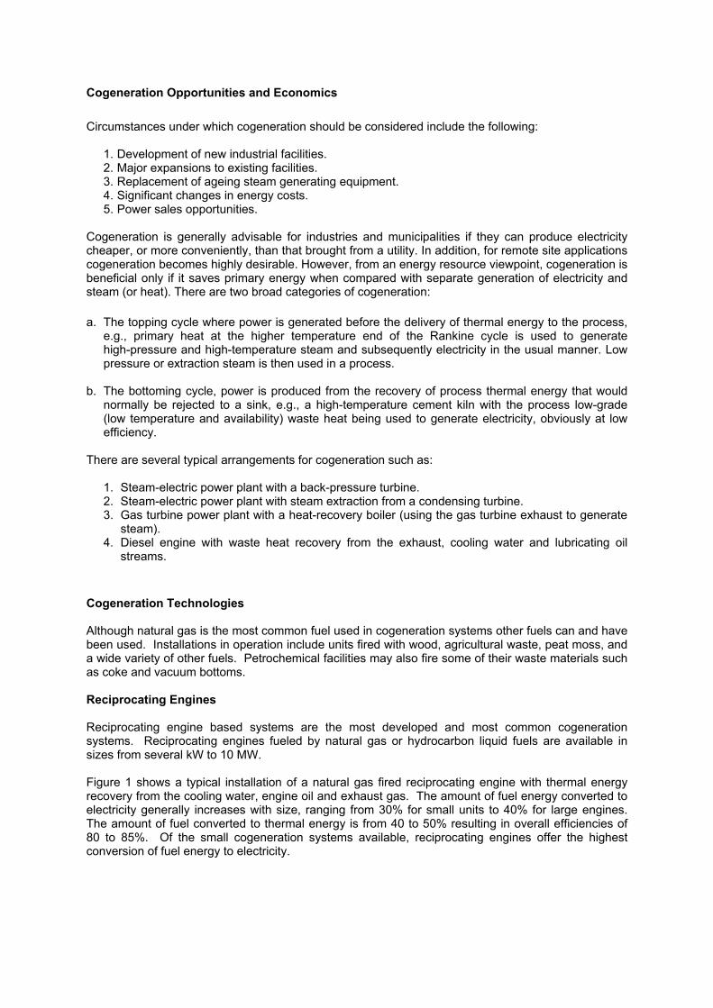
Figure 2: Example Gas Turbine Steam Turbine Combined Cycle with Some Heat Recovery
onstruction of cogeneration plants using gas turbines is well developed commercial technology.
icroturbines
icroturbines are a recent development of the gas turbine industry. Generally ranging in size from 25
ecause of their simplicity (most designs have only one moving part), microturbines potentially have
thermal energy recovered from the cogeneration units supplies about 30% of the maximum thermal demand for the greenhouse. G CTurbines can be fueled with natural gas or oil. Units range in size from 500 kW to 250 MW. Efficiency generally improves with increasing size of the turbine. Ssteam turbine cycle can improve efficiencies further to over 50% for large units. Gas turbines generally have a higher capital cost than reciprocating engines with lower operating costs. For plants above 10 MW, gas turbines are generally less expensive than reciprocating engines. Gas turbines require a supply of high pressure natural gas and a natural gas compressor may be required. This will increase the capital cost and reduce the efficiency of conversion to electricity.
CTypical turbine exhaust temperature is about 500°C. A Heat Recovery Steam Generator (HRSG) is installed to recover energy from the turbine exhaust. The steam recovered is of sufficient quality to operate a steam turbine to generate further electricity. In a cogeneration application the steam from the HRSG would be used as process steam. Alternately the heat in the turbine exhaust can be used to drive an absorption chiller for building cooling or refrigeration. M Mto 500 kW, microturbines were developed from turbocharger turbines used in the truck and aircraft industry. Most microturbines are single-stage turbine with high rotating speeds (90,000 rpm) and often directly coupled to a generator. Efficiencies of conversion to electricity range from 15 to 30% depending on size, fuel supply pressure, and whether the design includes a recuperator. Microturbine exhaust temperatures are relatively low (about 200 to 300°C) and the waste heat can only be used to generate low pressure steam and/or hot water. Bvery low operating costs, although they have not been in commercial use long enough to confirm this. Due to their low efficiency of electricity production, microturbines are best applied in a cogeneration

application. The available sizes of 25 to 500 kW are ideally suited to hospitals, apartment buildings, and small industries where a hot water supply is required.
Figure 3: Microturbine Installation with Heat Recovery from the Turbine Exhaust
Barriers to Increased Use of Cogeneration Historically electricity production, distribution and sales have been controlled by large government owned utilities. There are numerous real and perceived barriers to moving from central power to a distributed network of relatively small cogeneration units, often operated by independent providers. Some of the barriers to cogeneration include: a) artificially low price for electricity Large central power plants and the associated transmission grid may have been installed at government cost or heavily subsidized by government funds. This usually leads to an artificially low price that is difficult for new cogeneration facilities to compete with. Also the environmental cost emissions of pollutants and greenhouse gas emissions are not accounted for in the price of electricity. Until greenhouse gas credit trading is established, there is little financial reward for the improved fuel efficiency of cogeneration systems. b) market power of existing electricity supplier Cogeneration systems that wish to tie into the existing transmission grid or sell power to the grid are subject to rules and regulations that are geared towards large central power plants. c) cost of cogeneration equipment Although fuel use efficiency is higher, the economies of scale usually result in a high capital equipment cost per kilowatt of electricity produced for small cogeneration plants. New technologies such as microturbines and Stirling engines have the potential to reduce this capital cost but not until production numbers increase. d) complexity and cost of transmission grid connection
Safety aspects and power quality requirements both increase the cost of equipment required to connect cogeneration systems to an existing transmission grid. The transmission grid operator
usually requires the ability to remotely turn off or disconnect from the grid the cogeneration unit for safety reasons. e) Undervaluing of System Reliability
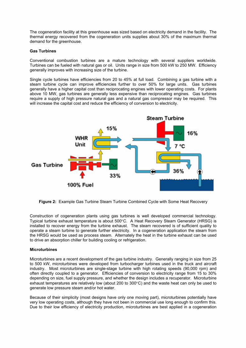
Cogeneration improves the reliability of power supply to the user. Most electricity users do not put a value on this improved reliability. In conclusion, wide adoption of distributed generation will require the availability of small, economical cogeneration units that require minimum maintenance. These units must have a high demonstrated reliability and there must be a large number of sites with both a demand for electricity and a demand for thermal energy. Both the technical and regulatory barriers to transmission grid connection will need to be addressed to maximize any investment in cogeneration for the user. Near Commercial Cogeneration Technologies Greater market penetration of small scale cogeneration will require the development of systems with high reliability, long lifetime, and lower capital and operating costs. There are several technologies under development or near commercial application that promise some or all of these benefits. Table 1 lists some of these technologies and their predicted conversion efficiency and capital cost as compared to conventional reciprocating engines. In a cogeneration application high efficiency of conversion to electricity may not be the determining factor in a technology selection. If the cogeneration system is sized to supply the thermal load, high reliability, fast response time and low capital cost may be more important factors.
Table 1: Comparison of New Generation Technologies Suitable for Cogeneration
Stirling Engines A Stirling engine is a closed system that converts thermal energy into mechanical energy by cyclic compression and expansion of the working fluid. The work energy can subsequently be converted into electricity using a generator. A Stirling engine can use several sources of heat, which makes it theoretically ideal for electricity generation from waste heat sources. Test engines have been run on solar heat, heat from gas, oil or biomass flames and waste heat from existing operations. As the Stirling engine uses an external combustor and all moving parts are sealed from the combustion products, unlike internal combustion engines and turbines there is no need for high quality fuel. By design, Stirling engines are quiet and should require little maintenance, which makes them attractive for remote sites or for domestic use.

Stirling engines are a technology within 1 to 5 years of commercial production, assuming they can be demonstrated to have acceptable reliability and energy conversion efficiency for their target markets. Stirling engines have several potential applications in cogeneration, conversion of waste heat to electricity and remote power generation. Beta test units are available at sizes up to 25 kW. To be effective, Stirling engines should be used in a cogeneration mode as efficiencies of conversion from heat energy to electricity are only 15 to 25%. When used in a cogeneration system, overall energy use will be 80 to 85%. Photovoltaics Photovoltaics can produce electricity with no emissions of pollutants or greenhouse gas and with zero cost for fuel. However the capital cost of current photovoltaic systems is high making them cost effective mainly in remote areas without existing fuel or electricity transmission lines. Photovoltaics convert only a portion of the incident solar radiation to electricity. The remainder is converted to heat or reflected from the solar panel. When combined with a solar hot water system, a photovoltaics unit could produce both electricity and hot water for space heating or domestic use. Fuel Cells Fuel cells are devices that directly convert chemical energy to electricity at high efficiency. There are several types of fuel cells with different operating conditions, fuel requirements and efficiencies. Fuel cell technology is developing rapidly due to their potential for simplicity and high efficiency of conversion to electricity. The leading fuel cell technologies are proton exchange membranes (PEM) and solid oxide electrolytes. PEM fuel cells operate at modest temperatures and may be applicable for cogeneration where the waste heat can be used in the form of hot water, such as building heating. Solid oxide fuel cells typically operate at temperatures over 800°C enabling cogeneration applications where the waste heat from the solid oxide fuel cell is used to generate high pressure steam. Solid oxide fuel cell are also being developed in combined cycle systems with the waste heat used to power a gas turbine. Generating electricity from both the fuel cell and the turbine results in the potential for converting 70% of the fuel energy to electricity. Integrated Gasification Combined Cycle (IGCC) Integrated Gasification Combined Cycle (IGCC) technology uses a combination of gas-fired turbine and steam turbine cycle to improve the efficiency of electricity generation. Coal or other hydrocarbon fuels are converted to synthesis gas (mainly a mixture of methane, carbon monoxide and carbon dioxide) in a gasification reactor followed by gas cleaning to remove particulate and sulphur compounds (H2S and COS) followed by combustion in a gas turbine generator set. Waste heat from the gasifier and from the exhaust of the gas turbine are used to generate steam, which generates electricity in a steam turbine generator set. Typically 65% of the electricity is produced in the gas turbine and 35% in the steam turbine (Rousaki and Couch, 2000). IGCC will have applications in very large cogeneration opportunities. IGCC has advantages over conventional fossil fueled steam cycle power plants including:
• • • • •
•
high efficiency of electricity generation (>50%), feedstock flexibility (coal, petroleum coke, biomass), lowest pollutant emissions of current technology for coal, less solid wastes, produces sulphur and inert ash slag, potential to produce other products (e.g. methanol, ammonia, hydrogen) and to integrate with petrochemical facilities, and recovery of CO2 with conventional, proven technology.
When constructed near a petrochemical facility, IGCC can be integrated with the facility to operate as a cogeneration facility, producing electricity, chemical feedstocks or high pressure steam for process heat. The fuel flexibility also enables waste destruction, such as heavy oils and coke, in the gasifier.

Application of Exergic Analysis to Total Energy Systems The rapid growth in population and industrialization, and the associated increase in energy demand and consumption, necessitates the development of techniques for designing environmentally compliant and efficient energy conversion systems. Subsequently, for current and future generating facilities, the traditional utility companies and the independent power producers (IPP’s) have been confronted with burgeoning operational restrictions, increased efficiency demands, variations in energy prices, concerns about future environmental legislation and the uncertainty over future utility demands. In addition, other possible interest groups, such as universities, hospitals or general industry, who believe cogeneration to be viable for their operations, need technical assistance in determining whether a total energy system is viable for them, the options available, and the reliability of the systems. This is perhaps understandable when the complexities of energy, environment and economics are projected into requirements for a total energy system, i.e., fuel selection, energy conversion selection, process requirements, costs (capital, O&M, life cycle), pollution reduction/control techniques, and system integration. With this multitude of design parameters, conditions and constraints any decisions on whether a system design meets acceptable specifications can only be made when traditional and advanced engineering analysis techniques are applied to the design problem, i.e., the total energy system is investigated, optimized thermodynamically, economically and environmentally. In recent times, many researchers have recognized the need to take into account some of the consequences of the second law in the thermodynamic analysis of processes and cycles. A review of this literature reveals that use of exergy principles enhances the understanding of thermal and chemical processes, allowing sources of inefficiency to be quantified. Such essentially thermodynamic considerations can be integrated with principles of engineering economics to determine the potential for cost-effective improvements of existing systems. Exergy and costing principles also can be used at the initial design stage to develop systems that are cost effective, fuel efficiency and environmentally friendly. However, even with the extensive analysis of the theoretical aspects of the second law analysis, there is still a noticeable gap between the theoretical analysis and the practical applications. It is this gap that has limited the development of design principles on an industrial basis. Several algorithms have been published for the synthesis of total energy systems. Most of them emphasize the optimization of thermodynamic parameters such as exergy or total efficiency, either with manual or computerized designed solutions, usually by analyzing a system with fixed temperature and given demand profiles for each level, but not necessarily the most economic solution. Other strategies minimize the operating cost for a given energy system, or the cost of utility generation based on a fixed structure and predetermined steam levels. Unfortunately, the possible reductions in emissions are mostly studied afterwards by modifying a selected solution. Areas for improvement in the application of advanced engineering analyses to total energy systems include:
1. The attainment of an optimal system structure. 2. A better understanding of subsystem component geometric optimization for maximum
efficiency. 3. The thermodynamic operation of the system for minimizing the total cost of meeting fixed and
unsteady-state demands for energy streams. 4. Selection of primary energy. 5. Life cycle analysis of the system.
The present technical need is threefold, firstly to produce practical design procedures which incorporate methodologies and techniques to analyze, improve, optimize, and to screen perhaps vastly different energy conversion systems with their associated environmental consequences; secondly, provide readily usable tools for the design/project engineer; and lastly provide the foundation for the continued investigation, evaluation, optimization and application of total energy systems.
Summary The many aspects of cogeneration systems, such as fuel, conversion process, generated energy streams and pollutant formation/control, generate a multi-faceted engineering environment where an
integrated design analysis can be applied. The goal of an integrated total energy system approach is the synthesis of all the processes from early concept to online operation. The advantage of integration of subsystems modules and separate databases is that other independently developed modules may be added without having to modify extensively the new module to conform to the format of the existing program. This provides flexibility to quickly incorporate new capabilities, and thus upgrade the existing program. Today, environmental considerations are an obvious factor in the development of power generation systems. The importance of this dimension will increase further in the years ahead as a result of ever more stringent environmental legislation and increasing public awareness of “green” issues. Hence, there is an urgent need to advise utility generating companies, system manufacturers and governments on how to optimise the application of power generating systems to improve operating performance and to facilitate emission reduction or elimination. However, advice can only be offered with a clear understanding of the principles of system operation, economic and effective emission regulation techniques. It is envisaged that going research, development and demonstration will provide robust and responsive methodologies for assessing the effectiveness and the economics of cogeneration systems in their operation, the optimum design and the environment impact. References Potential for Cogeneration in Ontario, prepared for Ministry of Energy, Science and Technology, August 2000. (available from the Ontario Ministry of Energy). Distributed Generation Strategic Plan, California Energy Commission, May 2002. (http://www.energy.ca.gov/distgen/strategic/strategic_plan.html) Spiewak, S., ‘Cogeneration and Small Power Production Manual, Third Edition. Guidebook for Combined Heat and Power, California Energy Commission, report #P700-00-011, October 2000.
Rousaki, K. and G. Couch, ‘Advanced Clean Coal Technologies and Low Value Coals’, IEA Coal Research Report CCC/39, IEA, London, UK, November, 2000.
Copyright 2002
The copyright of this document or product, whether in print or electronically stored on a CD or diskette or otherwise (the "Protected Work") is held by the Alberta Research Council Inc. (ARC). The Inter-American Association of Sanitary and Environmental Engineering (AIDIS) and its Chapters have been granted a license to copy, distribute and reproduce this Protected Work on a non-commercial and cost-recovery basis in Latin America and the Caribbean. This Protected Work shall not, in whole or in part, be copied, photocopied, reproduced, translated or reproduced to any electronic means or machine-readable form without prior consent in writing from ARC. Any copy of this Protected Work made under such consent must include this copyright notice. Funding This document has been exclusively prepared for the AIDIS-CANADA Environmental Project. The Project was funded by the Canadian International Development Agency (CIDA), managed by the Alberta Research Council Inc. (ARC) and AIDIS as the Latin American partner. Alberta Research Council Inc. (ARC) 250 Karl Clark Road Edmonton, Alberta T6N 1E4 Tel: (780) 450-4630 Fax: (780) 465-3308 Website: www.arc.ab.ca
Inter-American Association of Sanitary and Environmental Engineering Permanent Headquarters “Abel Wolman” Rua Nicolau Galiardi, 354-05429-010 Sao Paulo, SP, Brazil Tel: (55-11) 212-4080 Fax: (55-11) 814-2441 Website: [email protected]