Embed Size (px)
Citation preview
IntroductionConcerns over the environmental and healthrisks associated with the chrome-plating processhave led to the introduction of HVOF coatingsas an alternative to chrome plating in applica-tions where dynamic surfaces require wear andcorrosion resistance. Prior to the implementa-tion of HVOF coating technology, it was consid-ered sufficient to specify the requisite chromesurface finish strictly using the parameter Ra.
Ra is the arithmetic average of the surface fin-ish topography from the mean line. Given thepolishing effect on chrome surfaces during theinitial cycling that results from interaction withdynamic seals and bearings, the Ra parameterwas adequate, as any anomalies in the chromesurface topography would be removed over timein service.
As many industries transitioned to HVOFcoatings as an alternative to chrome, Ra alonebecame insufficient to define the necessary sur-face finish topography control parametersrequired for long and reliable service of dynamicseals and bearings. Unlike chrome, the finishedHVOF surface does not polish over time, mak-ing it crucial to specify the surface characteristicsnecessary to optimize the performance of the sys-tem. Recognizing the significant impact thatHVOF surfaces make on seal performance,Greene, Tweed has performed several applica-tion-specific evaluations of the surface topogra-
phy characteristics required to provide efficientseal performance.
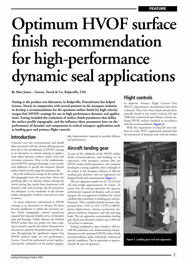
Aircraft landing gearAs part of the validation of the HVOF surfacefinish recommendation, and building on itsexperience with aerospace systems that useHVOF surface finish parameters, the companydeveloped a testing capability that is thought tobe unique to the aerospace industry. A full-sizelanding gear dynamic seal test apparatus wasdesigned built and commissioned (Figure 1).
This test apparatus stands over 6.7 m (22 feet)tall and weighs approximately 10 tonnes. Toassure that the testing represents the rigorousperformance required of dynamic seals on land-ing gear, the test apparatus simulates the criticalvariables that contribute to landing gear seal per-formance. These variables include pressure, tem-perature from –54°C to 93°C (–65°F to 200°F),piston displacement, velocity, acceleration, fre-quency, hardware clearances, and side and dragloads. The test apparatus accommodates landinggear shock strut dynamic surfaces up to 400 mm(16 inches) in diameter.
Testing completed to date includes a full air-craft life endurance test, demonstrating seal per-formance on the optimized HVOF surface finishrecommendation under wide-body commercialaircraft conditions. This is equivalent to approx-imately 30 years of operation.
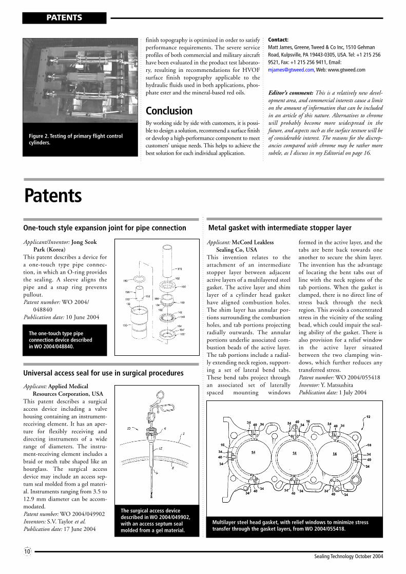
Flight controlsIn addition, Primary Flight Control Unit(PFCU) representative environments have beenevaluated. These have been based around thosetypically found in the newly evolving 345 bar(5000 psi) commercial and military systems uti-lizing HVOF surfaces finished in accordancewith the recommendation (Figure 2).
With the requirement of long life over mil-lions of cycles, PFCU applications demand thatthe interaction of dynamic seals with the surface
FEATURE
9Sealing Technology October 2004
Optimum HVOF surfacefinish recommendationfor high-performancedynamic seal applicationsBy Matt James – Greene, Tweed & Co, Kulpsville, USA
Testing at the product test laboratory in Kulpsville, Pennsylvania has helpedGreene, Tweed, in conjunction with several partners in the aerospace industry,to develop a recommendation for the optimum surface finish for high-velocityoxygen fuel (HVOF) coatings for use in high-performance dynamic seal applica-tions. Testing included the evaluation of surface finish parameters that definethe surface profile topography, and the influence these parameters have on theperformance of dynamic seal components in critical aerospace applications suchas landing gear and primary flight controls.
Figure 1. Landing gear seal test apparatus.
finish topography is optimized in order to satisfyperformance requirements. The severe serviceprofiles of both commercial and military aircrafthave been evaluated in the product test laborato-ry, resulting in recommendations for HVOFsurface finish topography applicable to thehydraulic fluids used in both applications, phos-phate ester and the mineral-based red oils.
ConclusionBy working side by side with customers, it is possi-ble to design a solution, recommend a surface finishor develop a high-performance component to meetcustomers’ unique needs. This helps to achieve thebest solution for each individual application.
Contact:Matt James, Greene, Tweed & Co Inc, 1510 GehmanRoad, Kulpsville, PA 19443-0305, USA. Tel: +1 215 2569521, Fax: +1 215 256 9411, Email:[email protected], Web: www.gtweed.com
Editor’s comment: This is a relatively new devel-opment area, and commercial interests cause a limiton the amount of information that can be includedin an article of this nature. Alternatives to chromewill probably become more widespread in thefuture, and aspects such as the surface texture will beof considerable interest. The reasons for the discrep-ancies compared with chrome may be rather moresubtle, as I discuss in my Editorial on page 16.
PATENTS
10Sealing Technology October 2004
PatentsOne-touch style expansion joint for pipe connection
Applicant/Inventor: Jong SeokPark (Korea)
This patent describes a device fora one-touch type pipe connec-tion, in which an O-ring providesthe sealing. A sleeve aligns thepipe and a snap ring preventspullout.Patent number: WO 2004/
048840Publication date: 10 June 2004
Universal access seal for use in surgical procedures
Applicant: Applied MedicalResources Corporation, USA
This patent describes a surgicalaccess device including a valvehousing containing an instrument-receiving element. It has an aper-ture for flexibly receiving anddirecting instruments of a widerange of diameters. The instru-ment-receiving element includes abraid or mesh tube shaped like anhourglass. The surgical accessdevice may include an access sep-tum seal molded from a gel materi-al. Instruments ranging from 3.5 to12.9 mm diameter can be accom-modated.Patent number: WO 2004/049902Inventors: S.V. Taylor et al.Publication date: 17 June 2004
The one-touch type pipe connection device described in WO 2004/048840.
The surgical access devicedescribed in WO 2004/049902,with an access septum sealmolded from a gel material.
Metal gasket with intermediate stopper layer
Applicant: McCord LeaklessSealing Co, USA
This invention relates to theattachment of an intermediatestopper layer between adjacentactive layers of a multilayered steelgasket. The active layer and shimlayer of a cylinder head gaskethave aligned combustion holes.The shim layer has annular por-tions surrounding the combustionholes, and tab portions projectingradially outwards. The annularportions underlie associated com-bustion beads of the active layer.The tab portions include a radial-ly extending neck region, support-ing a set of lateral bend tabs.These bend tabs project throughan associated set of laterallyspaced mounting windows
formed in the active layer, and thetabs are bent back towards oneanother to secure the shim layer.The invention has the advantageof locating the bent tabs out ofline with the neck regions of thetab portions. When the gasket isclamped, there is no direct line ofstress back through the neckregion. This avoids a concentratedstress in the vicinity of the sealingbead, which could impair the seal-ing ability of the gasket. There isalso provision for a relief windowin the active layer situatedbetween the two clamping win-dows, which further reduces anytransferred stress.Patent number: WO 2004/055418Inventor: Y. MatsushitaPublication date: 1 July 2004
Multilayer steel head gasket, with relief windows to minimize stresstransfer through the gasket layers, from WO 2004/055418.
Figure 2. Testing of primary flight controlcylinders.