Embed Size (px)
Citation preview
Optimum Design Parameters for a Therapist-ConstructedPositive-Expiratory-Pressure Therapy Bottle Device
Regis Gemerasca Mestriner PT, Rafael Oliveira Fernandes PT, Luís Carlos Steffen, andMarcio Vinícius Fagundes Donadio PT PhD
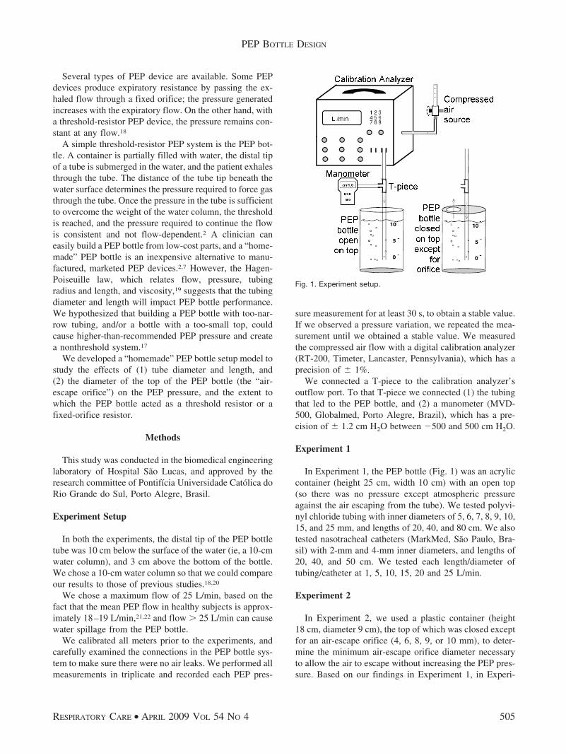
BACKGROUND: Positive-expiratory-pressure (PEP) therapy uses positive airway pressure gen-erated by a either a fixed-orifice resistor or a threshold resistor. We hypothesized that tubingdiameter and length, and the diameter of the PEP bottle’s air-escape orifice would impact the PEPpressure delivered to the airway and determine whether the PEP bottle acts as a threshold resistoror a fixed-orifice resistor. METHODS: We designed a model composed of a bottle partially filledwith water, a compressed air source, a pneumotachometer, and a manometer, to evaluate the effectsof various tubing diameters (range 2–25 mm inner diameter) and lengths (range 20–80 cm long).In the first set of experiments, the PEP bottle had an open top, so there was no pressure other thanthe atmospheric pressure against the air escaping from the immersed tubing. The distal tip of thetube was 10 cm below the surface of the water (ie, a water-column pressure of 10 cm H2O), and wetested flows of 1, 5, 10, 15, 20, and 25 L/min. In the second set of experiments we tested a PEP bottle,the top of which was closed except for an air-escape orifice (4, 6, 8, 9, or 10 mm). RESULTS: Withtubing of 2–6 mm inner diameter, the length of the tubing and the flow significantly affected thePEP pressure (ie, the system was not a threshold resistor). With tubing > 8 mm inner diameterthere were no significant PEP-pressure differences with any of the tubing lengths or flows tested,which indicates a threshold-resistor system. The 4-mm and 6-mm air-escape orifices significantlyincreased the PEP pressure, whereas the 8 mm air-escape orifice did not increase the PEP pressure.CONCLUSIONS: To obtain a threshold-resistor PEP bottle system (ie, the PEP pressure is gen-erated only by the water-column pressure), the tubing must be > 8 mm inner diameter, and theair-escape orifice must be > 8 mm. Key words: positive expiratory pressure, PEP, respiratory therapy.[Respir Care 2009;54(4):504–508. © 2009 Daedalus Enterprises]
Introduction
Positive-expiratory-pressure (PEP) therapy is a respira-tory therapy that applies resistance to expiration, to pro-
duce positive airway pressure.1-4 Since the 1930s, PEP hasbeen used to improve oxygenation, increase lung volume,and reduce venous return in patients with congestive heartfailure.2 PEP improves collateral ventilation,2,5-7 secretionclearance,8-11 aerosol distribution,2,12,13 and functional re-sidual capacity.2,3,14
The physiologic effects of PEP therapy are based mainlyon the equal-pressure-point theory. The equal-pressurepoint is where the intraluminal and extraluminal pressuresequalize across the airway. Proximal to the equal-pressurepoint (ie, toward the mouth), the external pressure aroundthe airway is greater than the pressure within it, and theairway is compressed, which limits the flow.15,16 PEP pre-vents small airways from collapsing, promotes better gasdistribution, and increases expiratory time and volume.2,16
The American Association for Respiratory Care recom-mends a PEP pressure of 10–20 cm H2O.17
Regis Gemerasca Mestriner PT, Rafael Oliveira Fernandes PT, and Mar-cio Vinícius Fagundes Donadio PT PhD are affiliated with Faculdade deEnfermagem, Nutricao e Fisioterapia, Pontifícia Universidade Catolicado Rio Grande do Sul. Luís Carlos Steffen is affiliated with the Depar-tamento de Engenharia Biomedica, Hospital Sao Lucas, Pontifícia Uni-versidade Catolica do Rio Grande do Sul, Porto Alegre, Rio Grande doSul, Brasil.
The authors declare no conflicts of interest.
Correspondence: Marcio Vinícius F Donadio PT PhD, Faculdade deEnfermagem, Nutricao e Fisioterapia, Pontifícia Universidade Catolicado Rio Grande do Sul, Av Ipiranga, 6681, Predio 12-8° Andar, Partenon,Porto Alegre, Rio Grande do Sul, Brasil. E-mail: [email protected].
504 RESPIRATORY CARE • APRIL 2009 VOL 54 NO 4
Several types of PEP device are available. Some PEPdevices produce expiratory resistance by passing the ex-haled flow through a fixed orifice; the pressure generatedincreases with the expiratory flow. On the other hand, witha threshold-resistor PEP device, the pressure remains con-stant at any flow.18
A simple threshold-resistor PEP system is the PEP bot-tle. A container is partially filled with water, the distal tipof a tube is submerged in the water, and the patient exhalesthrough the tube. The distance of the tube tip beneath thewater surface determines the pressure required to force gasthrough the tube. Once the pressure in the tube is sufficientto overcome the weight of the water column, the thresholdis reached, and the pressure required to continue the flowis consistent and not flow-dependent.2 A clinician caneasily build a PEP bottle from low-cost parts, and a “home-made” PEP bottle is an inexpensive alternative to manu-factured, marketed PEP devices.2,7 However, the Hagen-Poiseuille law, which relates flow, pressure, tubingradius and length, and viscosity,19 suggests that the tubingdiameter and length will impact PEP bottle performance.We hypothesized that building a PEP bottle with too-nar-row tubing, and/or a bottle with a too-small top, couldcause higher-than-recommended PEP pressure and createa nonthreshold system.17
We developed a “homemade” PEP bottle setup model tostudy the effects of (1) tube diameter and length, and(2) the diameter of the top of the PEP bottle (the “air-escape orifice”) on the PEP pressure, and the extent towhich the PEP bottle acted as a threshold resistor or afixed-orifice resistor.
Methods
This study was conducted in the biomedical engineeringlaboratory of Hospital Sao Lucas, and approved by theresearch committee of Pontifícia Universidade Catolica doRio Grande do Sul, Porto Alegre, Brasil.
Experiment Setup
In both the experiments, the distal tip of the PEP bottletube was 10 cm below the surface of the water (ie, a 10-cmwater column), and 3 cm above the bottom of the bottle.We chose a 10-cm water column so that we could compareour results to those of previous studies.18,20
We chose a maximum flow of 25 L/min, based on thefact that the mean PEP flow in healthy subjects is approx-imately 18–19 L/min,21,22 and flow � 25 L/min can causewater spillage from the PEP bottle.
We calibrated all meters prior to the experiments, andcarefully examined the connections in the PEP bottle sys-tem to make sure there were no air leaks. We performed allmeasurements in triplicate and recorded each PEP pres-
sure measurement for at least 30 s, to obtain a stable value.If we observed a pressure variation, we repeated the mea-surement until we obtained a stable value. We measuredthe compressed air flow with a digital calibration analyzer(RT-200, Timeter, Lancaster, Pennsylvania), which has aprecision of � 1%.
We connected a T-piece to the calibration analyzer’soutflow port. To that T-piece we connected (1) the tubingthat led to the PEP bottle, and (2) a manometer (MVD-500, Globalmed, Porto Alegre, Brazil), which has a pre-cision of � 1.2 cm H2O between �500 and 500 cm H2O.
Experiment 1
In Experiment 1, the PEP bottle (Fig. 1) was an acryliccontainer (height 25 cm, width 10 cm) with an open top(so there was no pressure except atmospheric pressureagainst the air escaping from the tube). We tested polyvi-nyl chloride tubing with inner diameters of 5, 6, 7, 8, 9, 10,15, and 25 mm, and lengths of 20, 40, and 80 cm. We alsotested nasotracheal catheters (MarkMed, Sao Paulo, Bra-sil) with 2-mm and 4-mm inner diameters, and lengths of20, 40, and 50 cm. We tested each length/diameter oftubing/catheter at 1, 5, 10, 15, 20 and 25 L/min.
Experiment 2
In Experiment 2, we used a plastic container (height18 cm, diameter 9 cm), the top of which was closed exceptfor an air-escape orifice (4, 6, 8, 9, or 10 mm), to deter-mine the minimum air-escape orifice diameter necessaryto allow the air to escape without increasing the PEP pres-sure. Based on our findings in Experiment 1, in Experi-
Fig. 1. Experiment setup.
PEP BOTTLE DESIGN
RESPIRATORY CARE • APRIL 2009 VOL 54 NO 4 505
ment 2 we used tubing with an inner diameter of 8 mm. Asin Experiment 1, the water column was 10 cm.
Statistical Analysis
Values are expressed as mean � SD. With statisticssoftware (SPSS 11.5, SPSS, Chicago, Illinois) we ana-lyzed the relationships between the tubing lengths andflows with 2-way analysis of variance for repeated mea-sures, followed by the Bonferroni test for multiple com-parisons, when indicated. Differences were considered sig-nificant when P � .05. Because a 10-cm water columnwas used in both experiments, all systems that showedpressures � 10 cm H2O were considered inadequate.
Results
Experiment 1
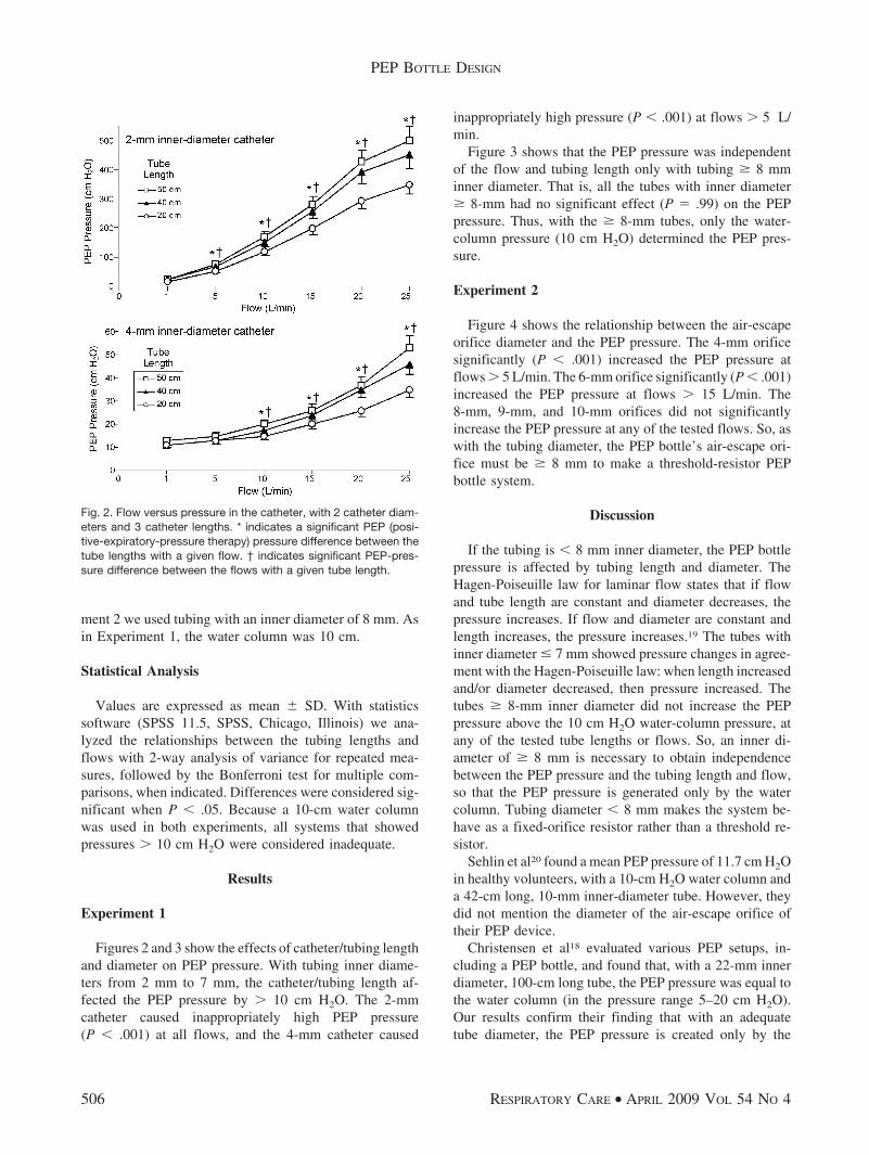
Figures 2 and 3 show the effects of catheter/tubing lengthand diameter on PEP pressure. With tubing inner diame-ters from 2 mm to 7 mm, the catheter/tubing length af-fected the PEP pressure by � 10 cm H2O. The 2-mmcatheter caused inappropriately high PEP pressure(P � .001) at all flows, and the 4-mm catheter caused
inappropriately high pressure (P � .001) at flows � 5 L/min.
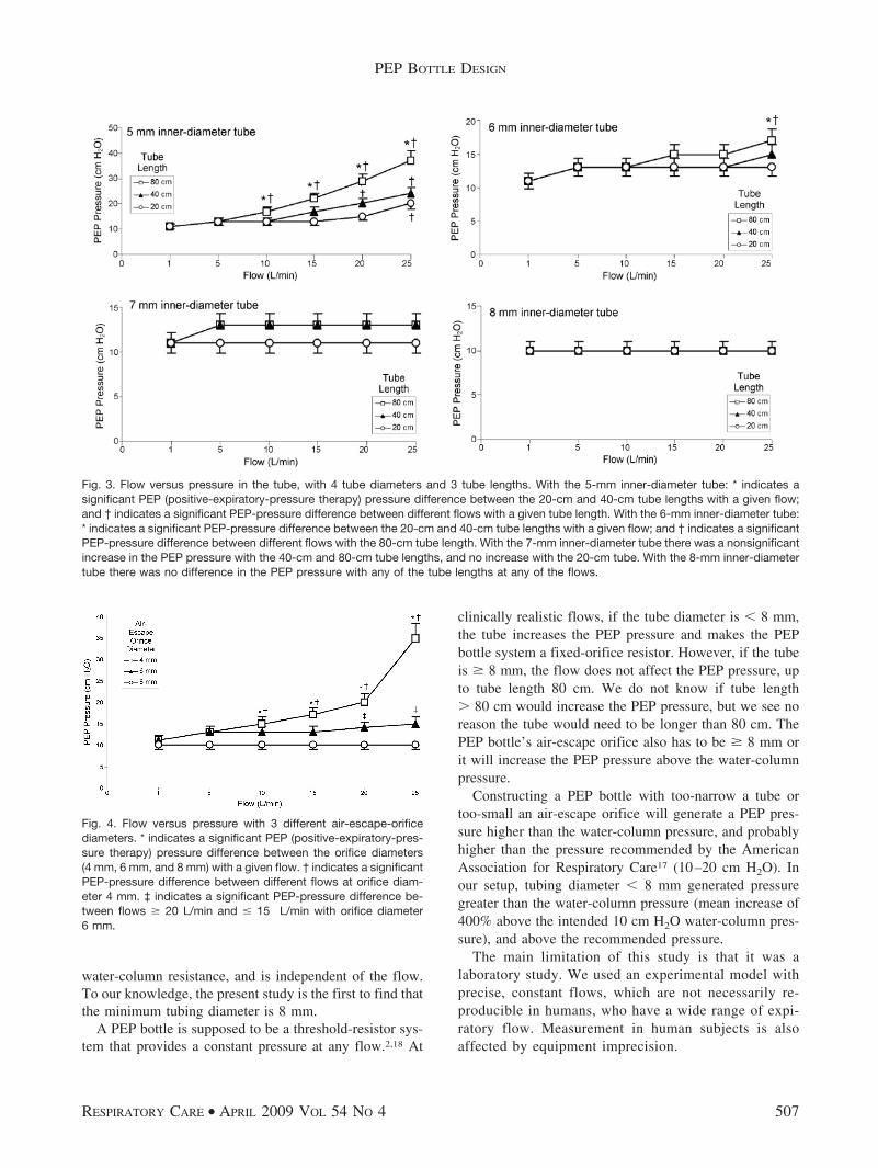
Figure 3 shows that the PEP pressure was independentof the flow and tubing length only with tubing � 8 mminner diameter. That is, all the tubes with inner diameter� 8-mm had no significant effect (P � .99) on the PEPpressure. Thus, with the � 8-mm tubes, only the water-column pressure (10 cm H2O) determined the PEP pres-sure.
Experiment 2
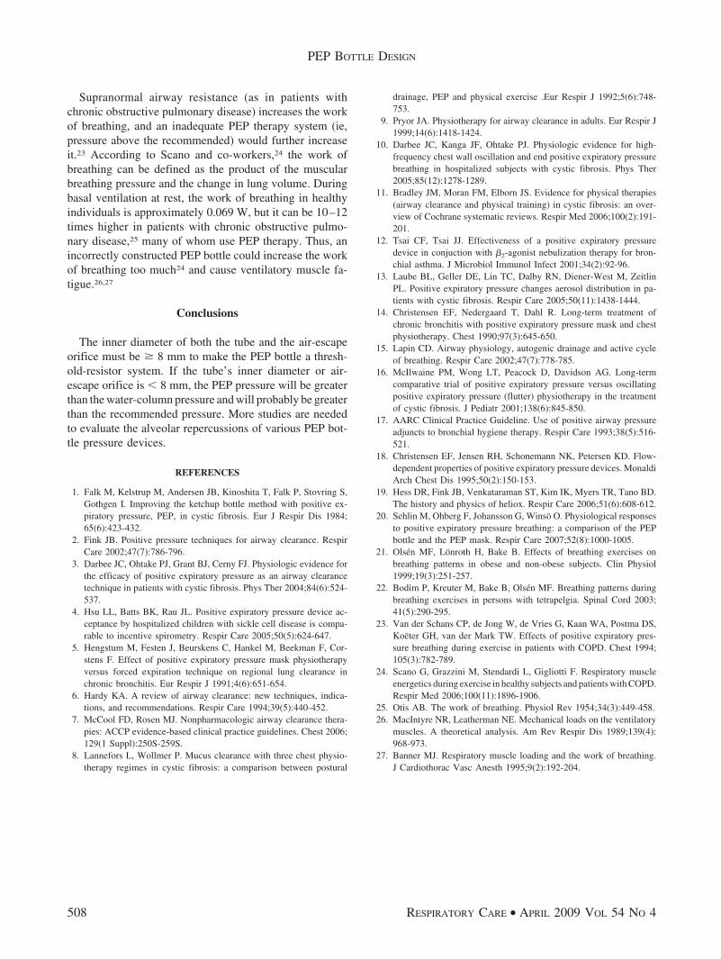
Figure 4 shows the relationship between the air-escapeorifice diameter and the PEP pressure. The 4-mm orificesignificantly (P � .001) increased the PEP pressure atflows � 5 L/min. The 6-mm orifice significantly (P � .001)increased the PEP pressure at flows � 15 L/min. The8-mm, 9-mm, and 10-mm orifices did not significantlyincrease the PEP pressure at any of the tested flows. So, aswith the tubing diameter, the PEP bottle’s air-escape ori-fice must be � 8 mm to make a threshold-resistor PEPbottle system.
Discussion
If the tubing is � 8 mm inner diameter, the PEP bottlepressure is affected by tubing length and diameter. TheHagen-Poiseuille law for laminar flow states that if flowand tube length are constant and diameter decreases, thepressure increases. If flow and diameter are constant andlength increases, the pressure increases.19 The tubes withinner diameter � 7 mm showed pressure changes in agree-ment with the Hagen-Poiseuille law: when length increasedand/or diameter decreased, then pressure increased. Thetubes � 8-mm inner diameter did not increase the PEPpressure above the 10 cm H2O water-column pressure, atany of the tested tube lengths or flows. So, an inner di-ameter of � 8 mm is necessary to obtain independencebetween the PEP pressure and the tubing length and flow,so that the PEP pressure is generated only by the watercolumn. Tubing diameter � 8 mm makes the system be-have as a fixed-orifice resistor rather than a threshold re-sistor.
Sehlin et al20 found a mean PEP pressure of 11.7 cm H2Oin healthy volunteers, with a 10-cm H2O water column anda 42-cm long, 10-mm inner-diameter tube. However, theydid not mention the diameter of the air-escape orifice oftheir PEP device.
Christensen et al18 evaluated various PEP setups, in-cluding a PEP bottle, and found that, with a 22-mm innerdiameter, 100-cm long tube, the PEP pressure was equal tothe water column (in the pressure range 5–20 cm H2O).Our results confirm their finding that with an adequatetube diameter, the PEP pressure is created only by the
Fig. 2. Flow versus pressure in the catheter, with 2 catheter diam-eters and 3 catheter lengths. * indicates a significant PEP (posi-tive-expiratory-pressure therapy) pressure difference between thetube lengths with a given flow. † indicates significant PEP-pres-sure difference between the flows with a given tube length.
PEP BOTTLE DESIGN
506 RESPIRATORY CARE • APRIL 2009 VOL 54 NO 4
water-column resistance, and is independent of the flow.To our knowledge, the present study is the first to find thatthe minimum tubing diameter is 8 mm.
A PEP bottle is supposed to be a threshold-resistor sys-tem that provides a constant pressure at any flow.2,18 At
clinically realistic flows, if the tube diameter is � 8 mm,the tube increases the PEP pressure and makes the PEPbottle system a fixed-orifice resistor. However, if the tubeis � 8 mm, the flow does not affect the PEP pressure, upto tube length 80 cm. We do not know if tube length� 80 cm would increase the PEP pressure, but we see noreason the tube would need to be longer than 80 cm. ThePEP bottle’s air-escape orifice also has to be � 8 mm orit will increase the PEP pressure above the water-columnpressure.
Constructing a PEP bottle with too-narrow a tube ortoo-small an air-escape orifice will generate a PEP pres-sure higher than the water-column pressure, and probablyhigher than the pressure recommended by the AmericanAssociation for Respiratory Care17 (10–20 cm H2O). Inour setup, tubing diameter � 8 mm generated pressuregreater than the water-column pressure (mean increase of400% above the intended 10 cm H2O water-column pres-sure), and above the recommended pressure.
The main limitation of this study is that it was alaboratory study. We used an experimental model withprecise, constant flows, which are not necessarily re-producible in humans, who have a wide range of expi-ratory flow. Measurement in human subjects is alsoaffected by equipment imprecision.
Fig. 3. Flow versus pressure in the tube, with 4 tube diameters and 3 tube lengths. With the 5-mm inner-diameter tube: * indicates asignificant PEP (positive-expiratory-pressure therapy) pressure difference between the 20-cm and 40-cm tube lengths with a given flow;and † indicates a significant PEP-pressure difference between different flows with a given tube length. With the 6-mm inner-diameter tube:* indicates a significant PEP-pressure difference between the 20-cm and 40-cm tube lengths with a given flow; and † indicates a significantPEP-pressure difference between different flows with the 80-cm tube length. With the 7-mm inner-diameter tube there was a nonsignificantincrease in the PEP pressure with the 40-cm and 80-cm tube lengths, and no increase with the 20-cm tube. With the 8-mm inner-diametertube there was no difference in the PEP pressure with any of the tube lengths at any of the flows.
Fig. 4. Flow versus pressure with 3 different air-escape-orificediameters. * indicates a significant PEP (positive-expiratory-pres-sure therapy) pressure difference between the orifice diameters(4 mm, 6 mm, and 8 mm) with a given flow. † indicates a significantPEP-pressure difference between different flows at orifice diam-eter 4 mm. ‡ indicates a significant PEP-pressure difference be-tween flows � 20 L/min and � 15 L/min with orifice diameter6 mm.
PEP BOTTLE DESIGN
RESPIRATORY CARE • APRIL 2009 VOL 54 NO 4 507
Supranormal airway resistance (as in patients withchronic obstructive pulmonary disease) increases the workof breathing, and an inadequate PEP therapy system (ie,pressure above the recommended) would further increaseit.23 According to Scano and co-workers,24 the work ofbreathing can be defined as the product of the muscularbreathing pressure and the change in lung volume. Duringbasal ventilation at rest, the work of breathing in healthyindividuals is approximately 0.069 W, but it can be 10–12times higher in patients with chronic obstructive pulmo-nary disease,25 many of whom use PEP therapy. Thus, anincorrectly constructed PEP bottle could increase the workof breathing too much24 and cause ventilatory muscle fa-tigue.26,27
Conclusions
The inner diameter of both the tube and the air-escapeorifice must be � 8 mm to make the PEP bottle a thresh-old-resistor system. If the tube’s inner diameter or air-escape orifice is � 8 mm, the PEP pressure will be greaterthan the water-column pressure and will probably be greaterthan the recommended pressure. More studies are neededto evaluate the alveolar repercussions of various PEP bot-tle pressure devices.
REFERENCES
1. Falk M, Kelstrup M, Andersen JB, Kinoshita T, Falk P, Stovring S,Gothgen I. Improving the ketchup bottle method with positive ex-piratory pressure, PEP, in cystic fibrosis. Eur J Respir Dis 1984;65(6):423-432.
2. Fink JB. Positive pressure techniques for airway clearance. RespirCare 2002;47(7):786-796.
3. Darbee JC, Ohtake PJ, Grant BJ, Cerny FJ. Physiologic evidence forthe efficacy of positive expiratory pressure as an airway clearancetechnique in patients with cystic fibrosis. Phys Ther 2004;84(6):524-537.
4. Hsu LL, Batts BK, Rau JL. Positive expiratory pressure device ac-ceptance by hospitalized children with sickle cell disease is compa-rable to incentive spirometry. Respir Care 2005;50(5):624-647.
5. Hengstum M, Festen J, Beurskens C, Hankel M, Beekman F, Cor-stens F. Effect of positive expiratory pressure mask physiotherapyversus forced expiration technique on regional lung clearance inchronic bronchitis. Eur Respir J 1991;4(6):651-654.
6. Hardy KA. A review of airway clearance: new techniques, indica-tions, and recommendations. Respir Care 1994;39(5):440-452.
7. McCool FD, Rosen MJ. Nonpharmacologic airway clearance thera-pies: ACCP evidence-based clinical practice guidelines. Chest 2006;129(1 Suppl):250S-259S.
8. Lannefors L, Wollmer P. Mucus clearance with three chest physio-therapy regimes in cystic fibrosis: a comparison between postural
drainage, PEP and physical exercise .Eur Respir J 1992;5(6):748-753.
9. Pryor JA. Physiotherapy for airway clearance in adults. Eur Respir J1999;14(6):1418-1424.
10. Darbee JC, Kanga JF, Ohtake PJ. Physiologic evidence for high-frequency chest wall oscillation and end positive expiratory pressurebreathing in hospitalized subjects with cystic fibrosis. Phys Ther2005;85(12):1278-1289.
11. Bradley JM, Moran FM, Elborn JS. Evidence for physical therapies(airway clearance and physical training) in cystic fibrosis: an over-view of Cochrane systematic reviews. Respir Med 2006;100(2):191-201.
12. Tsai CF, Tsai JJ. Effectiveness of a positive expiratory pressuredevice in conjuction with �2-agonist nebulization therapy for bron-chial asthma. J Microbiol Immunol Infect 2001;34(2):92-96.
13. Laube BL, Geller DE, Lin TC, Dalby RN, Diener-West M, ZeitlinPL. Positive expiratory pressure changes aerosol distribution in pa-tients with cystic fibrosis. Respir Care 2005;50(11):1438-1444.
14. Christensen EF, Nedergaard T, Dahl R. Long-term treatment ofchronic bronchitis with positive expiratory pressure mask and chestphysiotherapy. Chest 1990;97(3):645-650.
15. Lapin CD. Airway physiology, autogenic drainage and active cycleof breathing. Respir Care 2002;47(7):778-785.
16. McIlwaine PM, Wong LT, Peacock D, Davidson AG. Long-termcomparative trial of positive expiratory pressure versus oscillatingpositive expiratory pressure (flutter) physiotherapy in the treatmentof cystic fibrosis. J Pediatr 2001;138(6):845-850.
17. AARC Clinical Practice Guideline. Use of positive airway pressureadjuncts to bronchial hygiene therapy. Respir Care 1993;38(5):516-521.
18. Christensen EF, Jensen RH, Schonemann NK, Petersen KD. Flow-dependent properties of positive expiratory pressure devices. MonaldiArch Chest Dis 1995;50(2):150-153.
19. Hess DR, Fink JB, Venkataraman ST, Kim IK, Myers TR, Tano BD.The history and physics of heliox. Respir Care 2006;51(6):608-612.
20. Sehlin M, Ohberg F, Johansson G, Winso O. Physiological responsesto positive expiratory pressure breathing: a comparison of the PEPbottle and the PEP mask. Respir Care 2007;52(8):1000-1005.
21. Olsen MF, Lonroth H, Bake B. Effects of breathing exercises onbreathing patterns in obese and non-obese subjects. Clin Physiol1999;19(3):251-257.
22. Bodim P, Kreuter M, Bake B, Olsen MF. Breathing patterns duringbreathing exercises in persons with tetrapelgia. Spinal Cord 2003;41(5):290-295.
23. Van der Schans CP, de Jong W, de Vries G, Kaan WA, Postma DS,Koeter GH, van der Mark TW. Effects of positive expiratory pres-sure breathing during exercise in patients with COPD. Chest 1994;105(3):782-789.
24. Scano G, Grazzini M, Stendardi L, Gigliotti F. Respiratory muscleenergetics during exercise in healthy subjects and patients with COPD.Respir Med 2006;100(11):1896-1906.
25. Otis AB. The work of breathing. Physiol Rev 1954;34(3):449-458.26. MacIntyre NR, Leatherman NE. Mechanical loads on the ventilatory
muscles. A theoretical analysis. Am Rev Respir Dis 1989;139(4):968-973.
27. Banner MJ. Respiratory muscle loading and the work of breathing.J Cardiothorac Vasc Anesth 1995;9(2):192-204.
PEP BOTTLE DESIGN
508 RESPIRATORY CARE • APRIL 2009 VOL 54 NO 4