Embed Size (px)
Citation preview

1

2
3
Optimum Angle of Inclination of Taker-in Clothing in Carding Machine
Dr. Md. Ismail Chowdhury *
Abstract: The Parameters of card clothings have all along been a decisive factor in the increase in production rate of the machine and quality
of ultimate yarn. The angle of inclination of leading face of the taker-in clothing is an important parameter that determines the effectiveness of
interaction between fibres and the teeth of the clothing wire. This interaction is explained in the related literature from the viewpoint of
penetration of the clothing teeth into the fibres in that a tooth with greater inclination of its leading face penetrates into fibres comparatively
easily and disintegrates them more aggressively by opposing the frictional force. However this theory does not agree with mill practice where
almost the contrary is found to be true. This paper theoretically investigates the interaction from a novel viewpoint and determines the optimum
angle of inclination of taker-in clothing for revolving flat cards that conforms more closely to the practical values. In order that effective
interaction can take place between a fibre (or a tuft of fibres) and the leading face of a clothing tooth in the taker-in zone, two conditions should
be fulfilled: firstly the fibre should be lain within the friction cone at the point of contact; the second condition relates the tensions T1 and T2 at
the two ends of the fibre or the tuft of fibres. The two conditions have been expressed through mathematical expressions.
Keywords: Card clothings, fibre fringe, friction cone.
Introduction The card is the most vital machine in yarn manufacturing. Off all individual components of the card the metallic clothing
has the greatest influence on quality of yarn and productivity of the machine. The development of new clothing enabled,
for example, an increase in the production rate of the card from about 5 Kg/hour in 1965 to the present level of 80-100Kg/hour [1,2,3]. The main task of the card is to open the input tufts into individual fibres with gentle treatment. In this
regard the taker-in is the first working organ of the machine to interact with fibres. The entangled fibres entering the taker-
in zone come under the action of the metallic teeth of taker-in clothing. The interaction of fibers with the teeth of the clothing results in opening of the material that leads to individualization of about 50% of the fibres and elimination of
most of foreign impurities in the zone [1,4]. The fibres are then
transferred to the next organ of the machine i.e. the cylinder. In this case full transfer of fibres is very important as it
prevents lapping of fibres on the taker-in clothing. Besides, hold on fibres is required in order to reduce loss of good
fibres to the waste.
Effectiveness of all above mentioned functions depends on the geometric and kinematical parameters of feed table and metallic clothing of taker-in. Among them the angle of inclination of the leading face of taker-in clothing β (Fig. l) is
specially important as disintegration of tufts and individualization of fibres, hold on the fibres and transfer of them to the
cylinder are largely determined by this angle. The existing theoretical proposition and related calculation in respect of
optimum value of this angle does not conform to the practical value. This article investigates theoretically this angle and the interaction from a different and novel viewpoint in order to explain the interaction and determine the optimum value
of the angle.
Fig.1
Existing theoretical explanations of interaction between fibres and taker-in clothing
Niitsu Y. et al. [5] studied the effect of the angle of taker-in clothing on opening and individualization of fibres and found that with small angle of taker-in clothing better individualization of fibres is achieved.
__________________________
Associate Professor, Department of Textile Engineering, Ahsanullah University of Science and Technology, Dhaka.
4
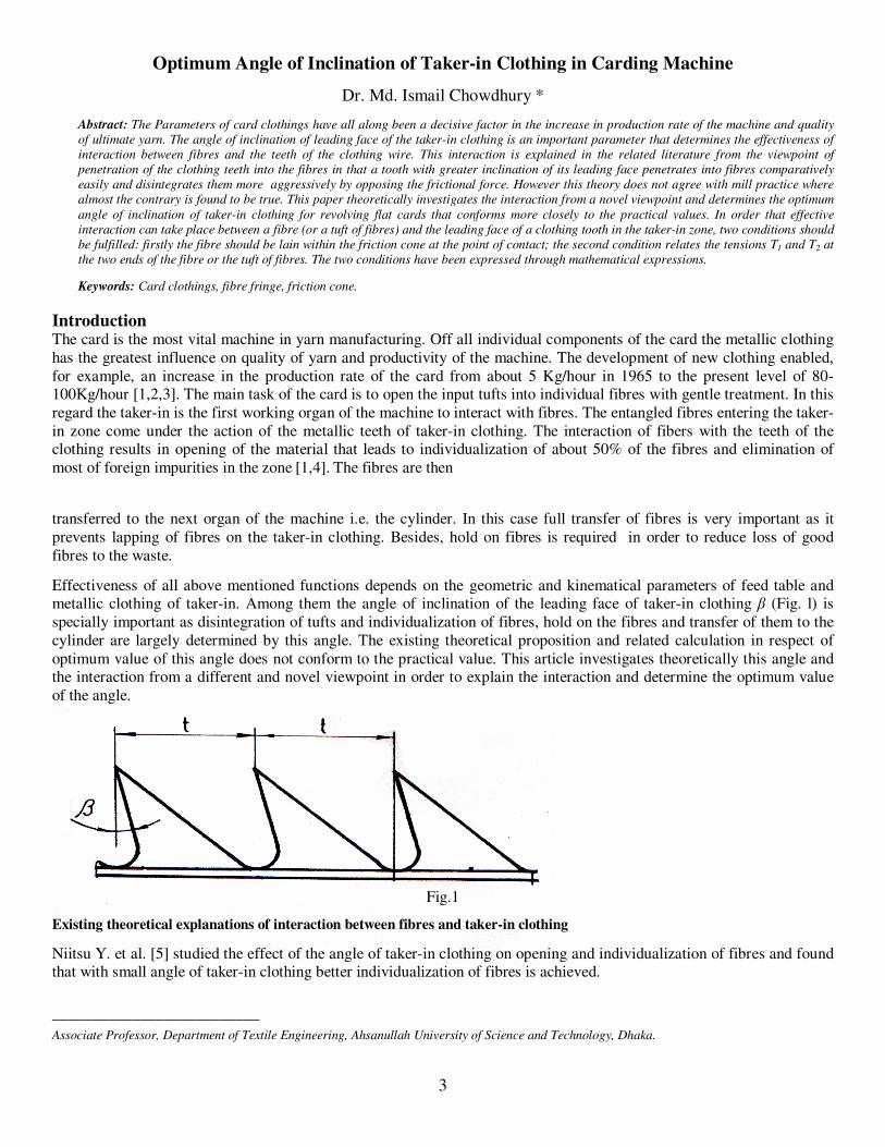
Lawrence C.A. [4] describes that the taker-in (licker-in) opens the fibre tufts effectively when one end of a tuft is
momentarily held while the teeth of taker-in pull individual fibres and groups of fibres from the other end. Figure (2) illustrates how the compression force on the batt (fibre mass fed to the card), resulting from the feed roller loading
increases as the batt approaches the taker-in [4]. The front of the feed plate facing the taker-in has a narrow horizontal
plateau and then it bevels steeply toward the taker-in, making a wedge space in which the batt fringe comes into contact
with the taker-in teeth. This wedge space enables the taker-in teeth to progressively penetrate the batt thickness. The top layer is first removed, bringing the remaining fibres nearer to the teeth. In this way most tufts are effectively opened.
Fig-2
The optimum value of the angle was determined theoretically from the view point of penetration of teeth of taker-in clothing into fibre fringe in the work [6] as follows:
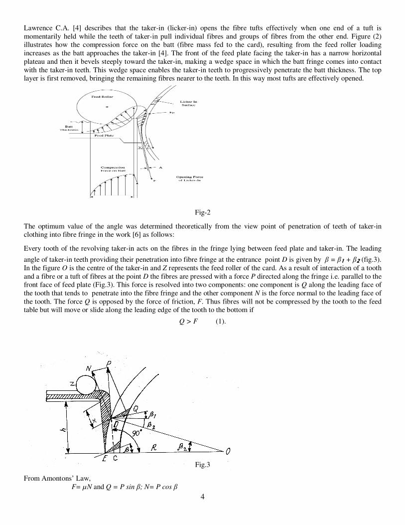
Every tooth of the revolving taker-in acts on the fibres in the fringe lying between feed plate and taker-in. The leading
angle of taker-in teeth providing their penetration into fibre fringe at the entrance point D is given by β = β1111 + β2222 (fig.3).
In the figure O is the centre of the taker-in and Z represents the feed roller of the card. As a result of interaction of a tooth
and a fibre or a tuft of fibres at the point D the fibres are pressed with a force P directed along the fringe i.e. parallel to the front face of feed plate (Fig.3). This force is resolved into two components: one component is Q along the leading face of
the tooth that tends to penetrate into the fibre fringe and the other component N is the force normal to the leading face of
the tooth. The force Q is opposed by the force of friction, F. Thus fibres will not be compressed by the tooth to the feed table but will move or slide along the leading edge of the tooth to the bottom if
Q > F (1).
Fig.3
From Amontons’ Law,
F= µN and Q = P sin β; N= P cos β

5
where µ is coefficient of friction
Putting the values of Q, N and F in (1) P sin β 1 ≥ µ P cos β 1
or tan β 1 ≥ µ; β 1 ≥ arc tan µ = ε where ε – angle of friction between fibre and
metal of the tooth or β 1 ≥ ε (2)
Angle β2 is calculated from the triangle DOE, angle OCD is a right angled triangle, therefore β2=arc sin DC
/R
(where R is radius of the taker-in).
As β = β1111 + β2222 ; β ≥ є + arc sin DC
/R (3)
In the figure b = 25 mm, R=117 mm, x –the distance between top of working edge of feed plate and the point of entrance
of tooth into the fringe which is very small (0-2mm). Taking µ=.2 (ε =120) and x=0 the value of β is found out to be 25
0
.
In case of µ = .36 (ε =200), β = 32
0 .
So it follows from penetration point of view that the angle β should be not less than 250 and the larger the value of β the
greater is the penetration of the teeth into the fibre fringe by opposing the frictional force. As a result, better interaction
between fibres and clothing is likely to take place.
However, this proposition does not conform to practical experience, where almost the contrary is true. In practice, β is
around 50-10
0 for short and medium staple cotton and even it is equal to zero or negative for longer cottons and synthetic
fibres [4]. It may be mentioned here that such values are comparatively more conducive to transfer of fibres from the taker-in to the cylinder.
Thus the theory of sliding of the fibres along the leading face of tooth against the force of friction can not convincingly explain the interaction taking place between the fibers and the teeth of taker-in.
Interaction from the view point of stable equilibrium of fibre on the surface of metallic clothing The above mentioned interaction in the taker-in zone can be better explained by applying the theory or viewpoint of stable
position or equilibrium of a yarn on the surface of a winding package in winding process as described in [7]. According to
this theory high quality package of yarn can be obtained if the following two conditions are fulfilled during winding: i) Condition of form of yarn on the package and ii) Condition of tension of between the feed side and the uptake side ends of
the yarn.
The first condition may be expressed as
tan α ≤ tan θ ≤ tan ε = µ (4)
Where ε = angle of friction, µ - coefficient of friction, α – angle of inclination of the winding surface to the axis of rotation of the package, θ – angle of geodesic deviation, AB- a portion of yarn (or fibre) on the winding surface (or
clothing tooth),subtended by the angle dΨ ; (fig.4)
Fig.4
By applying the above mentioned theory to the case of the interaction between a tooth and a fibre (or a tuft of fibres) as in the region of feed plate and taker-in the condition of form may be written as follows:
-tan ε ≤ tan θ ≤ tan ε (5)
In (5), ε is the angle of friction between metal of tooth and fibre.
6
In this case, θ may be called as carding angle because it is the angle between the direction of fiber fringe and direction perpendicular to leading edge of the tooth(<PDN in fig.3 and <APB in fig.7). From (5) it follows that interactions
between fibres and metallic teeth of taker-in i.e plucking out of fibres by a tooth, combing of fibres and holding of the
fibres by a tooth are expected to take place if at the point of contact on a tooth, the fibre lies within the cone of friction. Not fulfilling of this condition towards the feed table means impossibility of seizure of fibre and its combing by the tooth,
and that toward the bottom of the tooth means gathering of fibre to that direction.
The second condition for stable equilibrium of yarn in winding package is given by the following formula:
T1 ≤ T2
( )dψθtanµcosθψ
0
22
e∫ −
(6)
Where T1, and T2 – tensions at the uptake side and feed side ends of yarn respectively, Ψ angle of contact of the yarn with
the winding surface.
The second condition may be stated as follows:
The yarn in contact with a winding surface remains stationery at a point on it (does not move parallel to its own axis) until the tension at the leading end exceeds the maximum possible value.
In case of interaction between a tooth and a fibre or a tuft of fibres in taker-in zone we can infer that the fibre in contact
with a tooth remains stationery at a point on the tooth surface of the taker-in (does not move along the tooth) until the
tension at any one end exceeds the maximum value.
Thus pulling out of one of the two ends of a fibre or a tuft held under pressure between feed place and feed roller,
combing of fibre in the fringe and holding of the fibre or the tuft on the surface of a tooth are possible if the fibre or the
tuft lies within the cone of friction i.e. when - µ ≤ θ ≤ + µ (7) and when one of the following two conditions is met:
T1 > T2
( )dψθtanµcosθψ
0
22
e∫ −
(8)
Or,
T2
( )dψθtanµcosθψ
0
22
e∫ −
≤ T1 ≤ T2
( )dψθtanµcosθψ
0
22
e∫ −
(9)
When the equation (8) is satisfied, the end 1 of the fibre (fig 4) remains held between feed roller and feed plate or in the
fringe and the fibre is combed by the edge of the tooth; it means the other end of the fibre, 2 is pulled out and straightened
and combed.
In case of fulfilment of (9), the fibre is seized on the surface of the tooth and carried over to the next organ if the ends are
not under the clamp of feed roller and feed plate or the fibre is cut if the ends are under the clamp.
Determination of optimum angle of inclination of taker-in clothing From what have been stated above, it follows that satisfaction of above two conditions i.e. the condition of form and the
condition of tension are necessary for effective interaction between fast moving teeth of taker-in and slowly moving fibres
in the feed plate- taker-in zone. It is evident from (7), (8) and (9) that fulfilment of the above mentioned conditions depends on the value of θ. So it is not all the same whatever angle θ we have got. Let us therefore see how different values
of angle θ affect the fulfillment of the condition of tension.
Let us consider the position of a fibre on the surface of a tooth moving with a velocity of v with its ends 1 and 2 at
distances 1λ and 2λ remaining in the fringe or under the clamp of feed roller and feed table (fig.5.a & b). Let T1 and T2
be respective tensions as the fibre is pulled out by the tooth 3. To establish relation between 1λ , 2λ and T1, T2 let us

7
consider an elementary length dS on the fibre at a distance λ from the centre of cross-section of the tooth (fig.6). Then the
external force on dS may be written as follow:
dT= λv2 dS (10)
(a) Fig. 5 (a & b) (b)
Fig.6
Where λ- Coefficient of resistance of the fibre as it is pulled out (comprised of µ and force of cohesion or of friction with
the surface of feed table).
The tension at the ends of fibre may be written in the following forms:
T1 = 0∫l λv2
dS (11)
T2 = 0∫2 λv2
dS (12) Considering λv2
as constant and integrating equations (11) and (12) and after rearranging we can get
T1 /T2 = 1λ / 2λ ≤
( )dψθtanµcosθψ
0
22
e∫ −
(13)
Now we can calculate the relations T1/T2 i.e. 1λ / 2λ for different values of angle θ, assuming µ=.36 and Ψ=1500 in (13)
and solving it as follows:
When θ =0; T2 0.389 ≤ T 1≤ T2 2.566
,, θ =50; T2 0.402 ≤ T1 ≤ T2 2.486
,, θ =100; T2 0.445 ≤ T1 ≤ T2 2.246 (14)

8
,, θ =150; T2 0.544 ≤ T1 ≤ T2 1.836
,, θ =19.80; T1 = T2
From (14) it follows that for θ = 0; 1λ / 2λ ≤ 2.566
and for θ = 19.8; 1λ / 2λ =1
Obviously under identical conditions with the value θ = 0 slipping out of fibres from the surface of the tooth will be minimum. Under such condition the fibre acquires most stable position on the surface of the tooth and thereby most
favorable condition is created for straightening, combing and individualization of fibres and consequently isolation of
foreign matters.
So θ = 0 is the optimum condition for effective interaction between fibres and clothing teeth along the fringe in the taker-
in region.
Now we can take notice of the fact that for any given angle of β the value of θ on a tooth changes as it passes along the
combing arc i.e. the fringe. This fact will be revealed from the fig.7. In the figure O is the centre of taker-in with a radius of R mm, P is the point of entrance of taker-in teeth into the fibre fringe, and G is the point where radius of taker-in is
generally installed perpendicular to the front face of feed table. Due to the changing nature of the angle of θ, optimum
condition can not be provided for all points on the arc. But an approach to this end may be made by selecting optimum
angle of inclination β.
To see how θ changes along the combing arc for different values of β, we require to show another fact that the value of θ at any point P on the arc is equal to the angle ωp, subtended by the arc PG at the centre of taker-in i.e. θ= ωp. (15)
Fig. 7
In order to prove that, we extend AP and BP up to the points C and D on OG; from the figure we see that
<OPD= 900; Therefore <DPC + <CPO=90
0 ---------- (16)
and <ACO= 90; Therefore <CPO + ωP=90
0------------ (17)
From equations (16) and (17), ωP = <DPC = θ --------- (18)
At the point G when β =0, θ=0 (as the taker-in is generally installed with its radius perpendicular to the front face of feed
plate at this point). At the moment we can draw perpendiculars on the leading edge of a revolving tooth at different points
on the combing arc, directed opposite to the direction of taken-in movement. In figure 8, OP1, OS1, and OE1 represent perpendiculars on the leading edge of the tooth at the points P, S and E respectively E being end point of fringe. It will be
observed that the perpendicular at G will be parallel to the direction of feed plate; However, above the point G, they are
directed to the right of the feed table and below the point G, they are directed to the left of it ((fig.8).

9
Fig.8
Fig.9
Considering that type of change along the arc with β = O, the values of θ at the points P, G and E on the arc will be ω 1+
ω 2, O and ω3 respectively (Fig 9). In case of β = ω1+ ω2, the corresponding values will be 0, -(ω1+ω2) and -( ω 1+ ω 2+
ω 3).
Table 1 below presents the change in value of the angle θ corresponding to the different values of β at the points P,G and
E, and total changes in the value of θ from the point P to the point E (with ω 1+ ω 2= 120 = ε; ω 3= 5
0)
Table 1
Value of θ with Positions of the
tooth at points β =O0 β =12
0 β =-12
0
Total change in the
value of θ from the
point P to the point …
P +120 O
0 +24
0 O
0
G O0 -12
0 +12
0 12
0
E -50 -17
0 +5
0 17
0
From the table it is evident that depending on the value of β the position of the tooth at points where θ =0 (most stable
position for the fiber on the tooth) change along the arc. Above these points if change in θ takes place to one half side of
friction cone, then below them the change in value of θ takes place to the other half side of the cone.

10
From Table 1 we can also see that in the case of β=0 the change in value of θ along the arc PGE is distributed to the both sides of the friction cone (from +12
0 through 0
0 to - 5
0) whereas in case of β = 12
0 and - 12
0 the changes take place only
in one side of the friction cone (from 00 through - 12
0 to - 17
0 and from +24
0 through +12
0 to + 5
0 respectively) without
passing through θ = 00. Here we can take into notice that in case of taker-in clothing with β < 0, the carding angle θ
decreases along the arc of interaction (proceeds towards middle of friction cone) gradually improving the condition of
form. In case of β > 0, the carding angle θ increases along the arc but goes away from the middle of the friction cone.
Thus combing and individualization of the fibres and their holding on the teeth along the arc of fringe depends on θ and its
value changes along the arc. The most favorable condition will be obtained if the value of θ at S is equal to zero (0). With
such value change in θ will be distributed to the both sides of friction cone equally by a value of ω/2 (ω= ω1+ ω1 + ω3).
Let us proceed now to find out β. The mid-point of arc is S and according to equation (18) ωp= θ. So at the point S, at the
centre of the arc θ is equal to zero. Therefore β = ω2 is the optimum angle of inclination of front face of taker-in teeth. Because with such value of taker-in teeth, θ will be 0 at S.
Now we can find out ω2 from the fig 8.
ω2 =2ω1- ω3 - ω2 = ω1- ω3= 1/2 ω - ω3
Thus the optimum angle of inclination β = 1/2 ω - ω3 (19)
ω and ω3 may be determined from the geometrical parameters of taker-in and feed plate assembly. Let us determine the
angle β for the teeth of a taker-in having radius equal to 117 mm (as in carding machine 1453/3 of Textima, Germany), b= 30mm, x=2mm, C=10mm, R=128mm for processing fine cotton (Fig.10).
Fig.10
Angle (ω 1+ ω 2) can be found from the triangle PGO.
ω1+ ω2 = arc sin b/R = arc sin 28/128 = 120 38′ 8″
ω3 = arc sin 10/28 = 4028′51″
ω = ω1 + ω2+ ω3 = 1706′ 59”
ω2 = ω/2- ω3 = 8033′30″-4
028′ 51″ =4
0 4′ 39″
i.e β = 404′39′
In the above calculation, as per construction of feed plate and with the calculated value of β=4°4’39”, the arc PE corresponds approximately to an angle equal to 17°and therefore the total change in θ is equal to 17
0; and θ/2=8.5
0 which
is lower than angle of friction, є. Therefore, at any point on the arc the fibre lies well inside the friction cone as demanded
by the first condition of stable position (eqn.7). Now if we consider the effective arc of interaction to be PG, and S, the middle point of the arc where θ should be equal to 0
0, then <SOP = <SOG = (ω1 + ω2) ÷ 2 = β and β = (arc sin b/R) ÷ 2
=120 38′ 8″ ÷ 2 = 6
0 19′ 4″.

11
In the case of taker-in clothing with zero inclination (β=0) the change in the carding angle, θ is distributed to the both
sides of the friction cone which means the clothing is neither much prone to compress the fibre to the feed plate nor is it choked with fibres. Therefore favourable condition is created for better interaction between fibres and clothing teeth by
fulfiling the conditions of form and tension.
Taker-in clothing with positive inclination (β >0) causes the fibres to slide along the tooth to the bottom. Such sliding of
fibres results in spreading of fibre tufts at different points along the teeth edges which is desirable, because spreading of
fibres at more points along the tooth edge means effective interaction between the fibres and teeth at more points as a result of fulfilment of the conditions of form and tension. However, the higher value of β entails greater difficulty of
transferring fibres to the cylinder. So with a view to facilitating transfer of fibres β should be close to 00 (and less than ε)
which will better fulfil the two conditions of from and tension.
On the other hand, taker-in clothings with negative value of β are less inclined to penetrating into the fibres and tend to
compress the fibre fringe to the feed plate. But, it does not happen so perhaps due to the compression force of fibre fringe
arising out of feed roller loading and the wedged position of the space of interaction between fibres and taker-in teeth that facilitate the clothing teeth progressively to penetrate the fibre fringe. In this case also β should be close to 0
0 (and less
than ε) which is more congenial to the fulfillment of the two conditions of form and tensions.
Conclusion: For effective interaction between fibres and taker-in teeth, the fibres should lie within the friction cone at the points of
contact. Ideal condition to this end could be obtained if carding angle, θ = 0 along the arc of interaction in the taker-in region.
Since θ is changeable on the arc of interaction and its value depends on the angle of inclination of taker-in clothing (β), the most favourable conditions is likely to be obtained if the value of θ is equal to zero degree at the middle of the arc of
interaction. In that case change in θ is distributed to the both sides of the friction cone that better fulfils conditions of form
and tension.
Taker-in clothings with negative inclination (β < 0) are comparatively less inclined to penetrate fibre fringe and tend to
compress fibre to the feed plate. However, along the fibre fringe carding angle, θ decreases and proceeds towards the middle of the friction cone gradually improving the condition of interaction between fibres and teeth. They are also more
conducive to transfer of fibre to the next organ of the machine.
On the ohter hand, taker-in clothings with positive inclination ((β > 0) are inclined to penetrate fibre fringe that results in
spreading of fibre tufts along teeth edge. Such spreading facilitates effective interaction between fibres and clothing
thanks to fulfilment of the conditions of form and tension at more points. The carding angle θ along the fibre fringe increases but goes away from the middle of friction cone. Greater inclination of the clothing is not suitable for fibre
transfer that restricts its use for long staple fibres.
The optimum angle of inclination of the leading face of taker-in clothing, β in the taker-in zone with a typical feed plate
was calculated to be around 50 which conforms more closely to the practical values in cotton carding.
References: [1]. W. Klein, Manual of Textile Technology, Volume -2, The Textile Institute, UK, 1995.
[2]. www.cottonyarnmarket.net/carding, Cotton Machine – Operating Principle.
[3]. Sayed Ibrahim, Spinning-Yarn Production, Iplik technologileri TU liberal Turkey 2010.
[4]. Lawrence, C,A, Fundamentals of Spun Yarn Technology, P.170-171, CRC press LLC, 2003.
[5] Niitsu Y et al: Opening action in the licker-in part. J. Text. Mach. Soc. Japan, 10, 218-228, 1964.
[6] Borzunob I.G, et al., Spinning of cotton and synthetic fibres, Moscow, 1982, P.156-158. [7] Svetnic F.F, Design of winding mechanisms of yarn, Moscow, 1984 p.5-12.