Embed Size (px)
Citation preview
Optimizing User Views for Workflows
Olivier BitonUniversity of PennsylvaniaPhiladelphia, PA [email protected]
Susan B. Davidson∗
University of PennsylvaniaPhiladelphia, PA 19104
Sanjeev Khanna†
University of PennsylvaniaPhiladelphia, PA 19104
Sudeepa Roy‡
University of PennsylvaniaPhiladelphia, PA 19104
ABSTRACTA technique called user views has recently been proposed tofocus user attention on relevant information in response toprovenance queries over workflow executions [1, 2]: Givenuser input on what modules in the workflow specificationare relevant to the user, a user view is a concise representa-tion that clusters together modules to create a small numberof composite modules (or clusters) such that (1) each com-posite module in a user view contains at most one relevant(atomic) module, thus assuming the “meaning” of that mod-ule; and (2) no control or data dependencies (either direct orindirect) are introduced (soundness) or removed (complete-ness) between relevant modules. The goal is to find a userview with a smallest number of composite modules.
We show that for workflow specifications that are generalgraphs, regardless of the number of distinct modules in theinput workflow and the structure of interaction betweenthem, there always exists a user view of size at most (2k−1−k)2 + k, where k is the number of relevant modules. More-over, a good user view with at most (2k−1 − k)2 + k clus-ters can be computed in polynomial time in the size of thegraph. We also show that this upper bound is tight. Thusin general graphs, the number of composite modules can beexponentially large in k even in an optimum user view forthe specification. We also give a characterization of a gooduser view in terms of structural properties of each cluster inthe user view.
However, for series-parallel workflow graphs, we show that
∗Supported by NSF Awards IIS-0513778, IIS-0629846 andSEI-II0612177.†Supported in part by a Guggenheim Fellowship, an IBMFaculty Award, and by NSF Award CCF-0635084.‡Supported by NSF Award IIS-0803524.
Permission to copy without fee all or part of this material is granted pro-vided that the copies are not made or distributed for direct commercial ad-vantage, the ACM copyright notice and the title of the publication and itsdate appear, and notice is given that copying is by permission of the ACM.To copy otherwise, or to republish, to post on servers or to redistribute tolists, requires a fee and/or special permissions from the publisher, ACM.ICDT 2009, March 23–25, 2009, Saint Petersburg, Russia.Copyright 2009 ACM 978-1-60558-423-2/09/0003 ...$5.00
there is always a user-view with at most 2k − 3 compos-ite modules; further, there exist series-parallel graphs whereevery user view requires at least 2k − 3 composite modules.Such graphs capture the structure of many scientific andother workflows that we have encountered in practice. Forthis class of graphs, we give a simple, linear time algorithmfor constructing an optimum user view for a given specifica-tion.
1. INTRODUCTIONWorkflow management systems have become increasinglypopular as a way of specifying and executing data-intensivescientific analyses (e.g., myGrid/Taverna [14], Kepler [5],VisTrails [12], and Chimera [11]) as well as business pro-cesses [7]. In such systems, a workflow can be graphicallydesigned by chaining together modules, where each modulemay take as input data from previous modules, parametersettings, and data coming from external data sources. Theworkflow can then be executed multiple times, using differ-ent initial input data and parameter settings, and poten-tially generating a large amount of intermediate and finaldata products.
Due to the explosion of data being produced by these “in-silico” experiments, provenance support in workflow systemshas become of paramount importance, as evidenced by re-cent workshops [3, 13] and surveys [4, 15]. By maintainingthe provenance of data, its validity and reliability can be un-derstood and results be made reproducible. Many workflowsystems are therefore beginning to provide tools to capture,query, and manage provenance (e.g., COMAD-Kepler [6]and VisTrails [12]). In these and other systems, the prove-nance of a data object is defined as the dependency graph ofmodule executions, their parameters, and the data objectspassed between module executions [9]. This information canbe gleaned from the log of operations performed, or may beexplicitly stored by the system.
However, since a workflow execution (or run) may comprisemany module executions (steps) and intermediate data ob-jects, the amount of information provided in response to aprovenance query can be overwhelming.
Furthermore, many of the modules and intermediate dataproducts may not be of interest to the user, for example,
310
modules that represent reformatting of data. Recent work(ZOOM [2]) has therefore presented a technique called “userviews” for focusing user attention on provenance informa-tion that is relevant to the user. The technique takes asinput a workflow specification and a set of relevant mod-ules, and creates a set of composite modules, each of whichrepresents a sub-workflow. The set of composite modulesforms the user’s view of the workflow specification, and isused to present provenance information that is relevant tothe user by hiding the intermediate data and sequence ofmodule executions within each composite module.
More formally, a user view is a partition of the workflowmodules. It induces a higher level workflow in which nodesrepresent composite modules in the partition and edges areinduced by dataflow between modules in different compositemodules. Provenance information is seen by the user withrespect to the flow of data between modules in his view.In [1, 2], views are automatically constructed given input onwhat modules the user finds relevant such that (1) a compos-ite module contains at most one relevant (atomic) module,thus assuming the “meaning” of that module; (2) no datadependencies (either direct or indirect) are introduced orremoved between relevant modules; and (3) the view can-not be made smaller by combining two composite modules.In this way, the meaning of the original workflow specifi-cation is preserved, and relevant provenance information isprovided to the user.
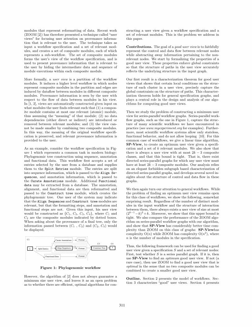
As an example, consider the workflow specification in Fig-ure 1 which represents a common task in modern biology:Phylogenomic tree construction using sequence, annotationand functional data. This workflow first accepts a set ofentries selected by the user from a database and suppliesthem to the Split Entries module. The entries are splitinto sequence information, which is passed to the Align Se-
quences, and annotation information, which is passed tothe Curate Annotations module. Additional Functionaldata may be extracted from a database. The annotation,alignment, and functional data are then reformatted andpassed to the Construct tree module, which creates thephylogenomic tree. One user of the system may indicatethat the Align Sequences and Construct tree modules arerelevant, but that the formatting steps, and annotation andfunctional steps are not. Given this input, his user viewwould be constructed as {C1, C2, C3, C4}, where C1 andC2 are the composite modules indicated by dotted boxes.When asking about the provenance of a final tree, only theinformation passed between (C1 , C2) and (C2, C3) wouldbe displayed.
t
Functional Data
Split Entries
Curate Annotations Format
Format
Format
C3 C4C2
C1
Construct Trees Align Sequences
Figure 1: Phylogenomic workflow
However, the algorithm of [2] does not always guarantee aminimum size user view, and leaves it as an open problemas to whether there are efficient, optimal algorithms for con-
structing a user view given a workflow specification and aset of relevant modules. This is the problem we address inthis paper.
Contributions. The goal of a good user view is to faithfullyrepresent the control and data flow between relevant nodeswhile abstracting away information pertaining to the non-relevant nodes. We start by formalizing the properties of agood user view. These properties enforce global constraintsso that the structure of paths in the user view accuratelyreflects the underlying structure in the input graph.
Our first result is a characterization theorem for good userviews that shows that certain local conditions on the struc-ture of each cluster in a user view, precisely capture theglobal constraints on the structure of paths. This character-ization theorem holds for general specification graphs, andplays a central role in the design and analysis of our algo-rithms for computing good user views.
Then we study the problem of constructing a minimum userview for series-parallel workflow graphs. Series-parallel work-flow graphs, such as the one in Figure 1, capture the struc-ture of many scientific workflows we have encountered inpractice (see www.myexperiment.org for examples). Further-more, most scientific workflow systems allow only stateless,functional behavior, and do not allow looping [10]. For thiscommon case of workflows, we give a linear time algorithm,SP-View, to create an optimum user view given a specifi-cation and a set of k relevant modules. We also show thatthere is always a user view with at most 2k − 3 compositeclasses, and that this bound is tight. That is, there existdirected series-parallel graphs for which any user view musthave at least 2k − 3 composite modules. Our analysis relieson an elegant forbidden subgraph based characterization ofdirected series-parallel graphs, and develops several novel in-sights about the structure of control and data flow in thesegraphs.
We then again turn our attention to general workflows. Whilethe problem of finding an optimum user view remains openfor this class of workflows, we show the following, somewhatsurprising result. Regardless of the number of distinct mod-ules in the input workflow and the structure of interactionbetween them, there always exists a user view of size at most(2k−1−k)2+k. Moreover, we show that this upper bound istight. We also compare the performance of the ZOOM algo-rithm on series-parallel workflow graphs with our algorithm,and show that SP-View has considerably better time com-plexity than ZOOM on this class of graphs: SP-Viewhascomplexity O(n) while ZOOM has complexity O(n2), wheren is the number of modules in the specification.
Thus, the following framework can be used for finding a gooduser view given a specification S and a set of relevant nodes:First, test whether S is a series parallel graph. If it is, thenuse SP-View to find an optimum good user view. If not (arare case), then use ZOOM to find a good user view that isoptimal in the sense that no two composite modules can becombined to create a smaller good user view.
Outline. Section 2 presents the model of workflows. Sec-tion 3 characterizes “good” user views. Section 4 presents
311
a linear-time algorithm for finding an optimum (good) userview for workflows represented by series-parallel graphs. Gen-eral graphs are considered in Section 5, together with ananalysis of the ZOOM algorithm. Section 6 compares theperformance of SP-View with ZOOM on series-parallel graphs.We conclude in Section 7.
2. MODEL AND DEFINITIONSGiven a graph G, we will use V (G) and E(G) to denote theset of the vertices and the edges in G respectively.
2.1 Workflow SpecificationsDefinition 1. A workflow specification (or simply a spec-
ification) (G, s, t,R) consists of
• a directed graph G such that each node v ∈ V (G)denotes a unique module in the workflow,
• a source node s ∈ V (G) and a sink node t ∈ V (G) suchthat s has no incoming edges, t has no outgoing edgesand every node v ∈ V (G) lies on some s ! t path inG, and
• a set R ⊆ V (G) of relevant modules in the workflow,where by convention, s, t ∈ R.
The special nodes s and t correspond to the input and theoutput modules in the workflow. We will use NR to denotethe set of non relevant modules in the workflow (i.e. NR= V (G) \ R) and k to denote size of R.
A node v ∈ V (G) is called an R-node, if v ∈ R and anNR-node if v ∈ NR. For any edge (u, v) ∈ E(G), u iscalled a predecessor of v and v is called a successor of u. Apredecessor u of v in G is an R-predecessor of v if u ∈ R.NR-predecessor, R-successor and NR-successor are definedsimilarly. A path p of length ≥ 1 is called an elementarypath if no intermediate node on p is an R-node.
2.2 Good User ViewsA user view for a workflow specification G is another directedgraph H such that the nodes of H are “clusters” of nodes ofG and the edges of H correspond to edges between nodes indifferent clusters. The formal definition is given below.
Definition 2. A user view for a workflow specification(G, s, t,R) is a pair (H,φ) where H is a directed graph andφ : V (G) → V (H) is a homomorphism such that
• if (u, v) ∈ E(G) then (φ(u), φ(v)) ∈ E(H), and con-versely, if (C, C′) ∈ E(H) then there exists u ∈ φ−1(C),v ∈ φ−1(C′) with (u, v) ∈ E(G).
• A self-loop (C, C), C ∈ V (H) is preserved in E(H) ifand only if there exists a cycle ρ such that for eachvertex u on ρ, φ(u) = C and there exists an R-nodeon ρ.
We will refer to a node C ∈ V (H) as a composite moduleor simply a cluster; it represents all modules u ∈ V (G) such
that φ(u) = C. We say an edge e = (u, v) in G is an origin ofan edge e′ = (C, C′) in H (or that, e induces e′) if φ(u) = Cand φ(v) = C′. Note that an edge in H can have multipleorigins in G; equivalently, multiple edges in G may inducethe same edge in H .
We discard any self-loop in H that does not correspond toa cycle containing an R-node in G. In this case we assumethat all the edges (u, v) ∈ E(G) on cycle ρ induce the selfloop. This preserves the presence of non-trivial elementarypaths from an R-node to itself and allows the execution ofa composite module containing an R-node r multiple timesif multiple executions of the module r were possible in theoriginal specification.
The size of a user view is the number of composite modulesin it, that is, |V (H)|. Our goal is to find a minimum sizeuser view H for a given specification while requiring thatthe view obey certain properties that we describe next.
We start by extending the notions of relevant nodes andelementary paths to a user view H . We will say a clusterC ∈ V (H) is a relevant cluster or an R-cluster if φ−1(C) ∩R &= ∅. Similarly, we will say a cluster C ∈ V (H) is non-relevant cluster or an NR-cluster if φ−1(C) ∩ R = ∅. Apath p of length ≥ 1 in H is called an elementary path if nointermediate cluster on p is an R-cluster.
Definition 3. A user view (H,φ) for a workflow specifica-tion (G, s, t,R) is said to be good if it satisfies the followingproperties [2]:
1. H is well-formed, that is, for any node C ∈ V (H), theset φ−1(C) contains at most one node from R.
2. H is sound w.r.t. data flow, that is, for every edge e′
on an elementary path that connects an R-cluster Cto an R-cluster C′ in H , each origin of the edge e′ lieson an elementary path from an R-node r to an R-noder′ in G such that r ∈ φ−1(C), r′ ∈ φ−1(C′).
3. H is complete w.r.t data flow, that is, for every edgee = (u, v) on an elementary path from an R-node r toan R-node r′ in G, either φ(u) = φ(v), or the edge e′
induced by e lies on an elementary path from φ(r) toφ(r′) in H .
We now state the motivation behind the above properties.As we said before, the R-nodes are relevant to the user, andthe goal is to be able to see the workflow relationship amongthe relevant nodes. Thus an R-cluster containing an R-nodeshould take on the meaning or role of the R-node that itcontains. So to preserve the identity of the R-clusters, werequire that each cluster in the workflow be well-formed.Since we are interested in preserving the “dependency” be-tween relevant modules in a good user view, two R-clustersshould be connected by an elementary path in the user viewif and only if the corresponding R-nodes are connected by anelementary path in the given specification. The soundnessproperty above ensures that the user view does not createany new elementary paths between a pair of R-clusters, that
312
is, elementary paths that did not exist between the corre-sponding R-nodes in the original workflow specification. Thecompleteness property, on the other hand, ensures that everyelementary path connecting a pair of R-clusters is preservedin the user view, modulo merging of nodes along such a pathinto a composite module. Thus the provenance informationprovided by a good user view is always consistent with theoriginal specification.
Note that the above properties trivially hold in any givenspecification G, hence the specification G is always a gooduser view of itself with φ(v) = {v} for each v ∈ V (G). Inany user view H , it is easy to see that for each v ∈ V (G),φ(v) is on a path from φ(s) to φ(t), as v is on a path froms to t in G. Later in Corollary 2 we will also show that ina good user view, φ(s) acts as the source cluster and φ(t)acts as the sink cluster, i.e. φ(s) and φ(t) do not have anyincoming edge and any outgoing edge respectively.
2.3 Series-Parallel GraphsA natural class of workflows is directed two terminal series-parallel (SP) graphs defined below.
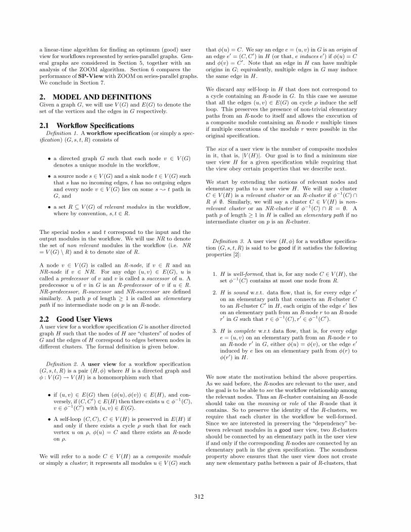
Definition 4. A directed two terminal series-parallelgraph is a directed multigraph G with a single source s anda single sink t (two terminals) that can be produced by asequence of the following operations:
• Basic SP-graph: Create a new graph consisting of asingle edge directed from s to t.
• Series Composition: Given two SP-graphs G1 andG2 with sources s1, s2 and sinks t1, t2 respectively,form a new graph G = S(G1, G2) by identifying s = s1,t1 = s2 and t = t2.
• Parallel Composition: Given two SP-graphs G1 andG2 with sources s1, s2 and sinks t1, t2 respectively,form a new graph G = P (G1, G2) by identifying s =s1 = s2 and t = t1 = t2.
G = P(G , G )
1
s1
s2
t 2
s =
=
=
t
t 2
s2
t 1t
s1s ==
= =
G1 G2
t 2
s2s1
t 1
G1 G2and G = S(G , G ) 1 2
(a) DirectedSP!graphs
(b) Series composition composition
(c) Parallel
21
t
Figure 2: An example of series and parallel compo-sitions
Examples of series and parallel compositions are shown inFigure 2. The following observations can be made from theinductive definition above.
Observation 1. Let G be a directed SP graph. Then,
1. Each node v ∈ V (G) is on a path from the start nodes to the sink node t, and
2. G is acyclic (that is, it is a DAG).
Definition 5. A directed graph G1 is said to contain asubgraph1 homeomorphic to a directed graph G2 if G2
can be obtained from G1 by a sequence of operations: (1)removal of an edge, or (2) replacement of two edges of theform (u, w) and (w, v) by the edge (u, v) when w has indegree= 1 and outdegree = 1.
We will use the following characterization of two terminaldirected SP graphs from [16].
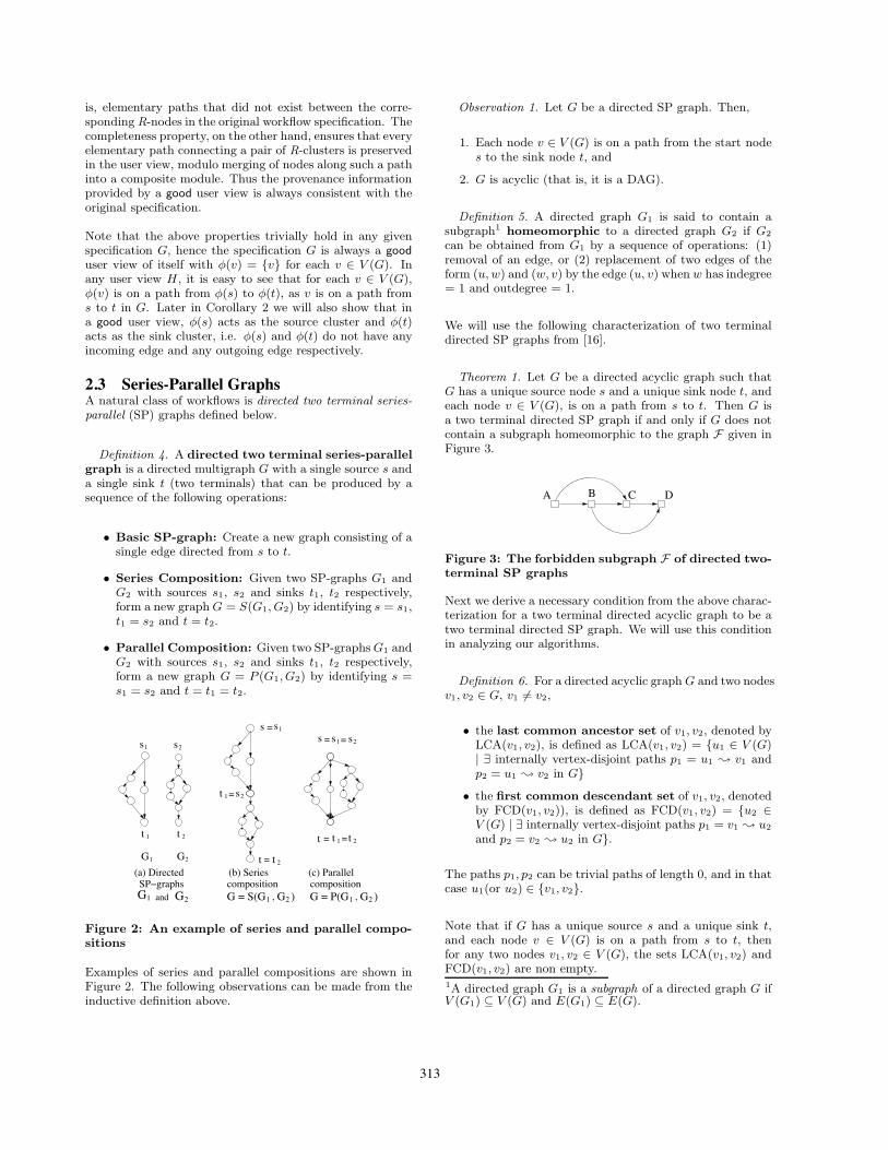
Theorem 1. Let G be a directed acyclic graph such thatG has a unique source node s and a unique sink node t, andeach node v ∈ V (G), is on a path from s to t. Then G isa two terminal directed SP graph if and only if G does notcontain a subgraph homeomorphic to the graph F given inFigure 3.
A B C D
Figure 3: The forbidden subgraph F of directed two-terminal SP graphs
Next we derive a necessary condition from the above charac-terization for a two terminal directed acyclic graph to be atwo terminal directed SP graph. We will use this conditionin analyzing our algorithms.
Definition 6. For a directed acyclic graph G and two nodesv1, v2 ∈ G, v1 "= v2,
• the last common ancestor set of v1, v2, denoted byLCA(v1, v2), is defined as LCA(v1, v2) = {u1 ∈ V (G)| ∃ internally vertex-disjoint paths p1 = u1 ! v1 andp2 = u1 ! v2 in G}
• the first common descendant set of v1, v2, denotedby FCD(v1, v2)), is defined as FCD(v1, v2) = {u2 ∈V (G) | ∃ internally vertex-disjoint paths p1 = v1 ! u2
and p2 = v2 ! u2 in G}.
The paths p1, p2 can be trivial paths of length 0, and in thatcase u1(or u2) ∈ {v1, v2}.
Note that if G has a unique source s and a unique sink t,and each node v ∈ V (G) is on a path from s to t, thenfor any two nodes v1, v2 ∈ V (G), the sets LCA(v1, v2) andFCD(v1, v2) are non empty.1A directed graph G1 is a subgraph of a directed graph G ifV (G1) ⊆ V (G) and E(G1) ⊆ E(G).
313
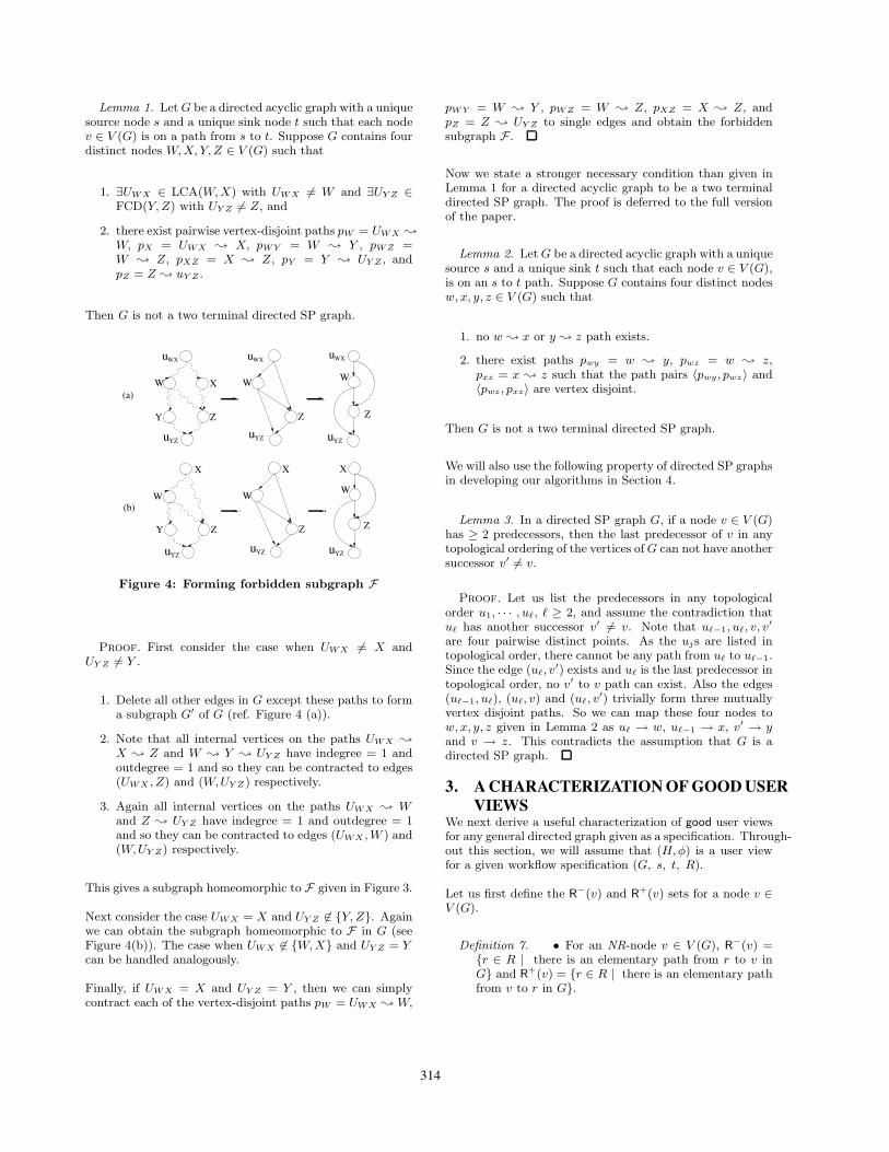
Lemma 1. Let G be a directed acyclic graph with a uniquesource node s and a unique sink node t such that each nodev ∈ V (G) is on a path from s to t. Suppose G contains fourdistinct nodes W, X, Y, Z ∈ V (G) such that
1. ∃UWX ∈ LCA(W,X) with UWX #= W and ∃UY Z ∈FCD(Y, Z) with UY Z #= Z, and
2. there exist pairwise vertex-disjoint paths pW = UWX !
W, pX = UWX ! X, pWY = W ! Y , pWZ =W ! Z, pXZ = X ! Z, pY = Y ! UY Z , andpZ = Z ! uY Z .
Then G is not a two terminal directed SP graph.
Z
uYZ uYZ uYZ
uYZuYZuYZ
uWX uWX uWX
(a)W X
Y Z
W
Z
W
Z
(b)W
X
Y Z
W
X
Z
W
X
Figure 4: Forming forbidden subgraph F
Proof. First consider the case when UWX #= X andUY Z #= Y .
1. Delete all other edges in G except these paths to forma subgraph G′ of G (ref. Figure 4 (a)).
2. Note that all internal vertices on the paths UWX !
X ! Z and W ! Y ! UY Z have indegree = 1 andoutdegree = 1 and so they can be contracted to edges(UWX , Z) and (W,UY Z) respectively.
3. Again all internal vertices on the paths UWX ! Wand Z ! UY Z have indegree = 1 and outdegree = 1and so they can be contracted to edges (UWX , W ) and(W,UY Z) respectively.
This gives a subgraph homeomorphic to F given in Figure 3.
Next consider the case UWX = X and UY Z #∈ {Y, Z}. Againwe can obtain the subgraph homeomorphic to F in G (seeFigure 4(b)). The case when UWX #∈ {W, X} and UY Z = Ycan be handled analogously.
Finally, if UWX = X and UY Z = Y , then we can simplycontract each of the vertex-disjoint paths pW = UWX ! W,
pWY = W ! Y , pWZ = W ! Z, pXZ = X ! Z, andpZ = Z ! UY Z to single edges and obtain the forbiddensubgraph F .
Now we state a stronger necessary condition than given inLemma 1 for a directed acyclic graph to be a two terminaldirected SP graph. The proof is deferred to the full versionof the paper.
Lemma 2. Let G be a directed acyclic graph with a uniquesource s and a unique sink t such that each node v ∈ V (G),is on an s to t path. Suppose G contains four distinct nodesw, x, y, z ∈ V (G) such that
1. no w ! x or y ! z path exists.
2. there exist paths pwy = w ! y, pwz = w ! z,pxz = x ! z such that the path pairs 〈pwy , pwz〉 and〈pwz, pxz〉 are vertex disjoint.
Then G is not a two terminal directed SP graph.
We will also use the following property of directed SP graphsin developing our algorithms in Section 4.
Lemma 3. In a directed SP graph G, if a node v ∈ V (G)has ≥ 2 predecessors, then the last predecessor of v in anytopological ordering of the vertices of G can not have anothersuccessor v′ #= v.
Proof. Let us list the predecessors in any topologicalorder u1, · · · , u!, ! ≥ 2, and assume the contradiction thatu! has another successor v′ #= v. Note that u!−1, u!, v, v′
are four pairwise distinct points. As the ujs are listed intopological order, there cannot be any path from u! to u!−1.Since the edge (u!, v
′) exists and u! is the last predecessor intopological order, no v′ to v path can exist. Also the edges(u!−1, u!), (u!, v) and (u!, v
′) trivially form three mutuallyvertex disjoint paths. So we can map these four nodes tow, x, y, z given in Lemma 2 as u! → w, u!−1 → x, v′ → yand v → z. This contradicts the assumption that G is adirected SP graph.
3. A CHARACTERIZATIONOFGOODUSERVIEWS
We next derive a useful characterization of good user viewsfor any general directed graph given as a specification. Through-out this section, we will assume that (H,φ) is a user viewfor a given workflow specification (G, s, t, R).
Let us first define the R−(v) and R+(v) sets for a node v ∈V (G).
Definition 7. • For an NR-node v ∈ V (G), R−(v) ={r ∈ R | there is an elementary path from r to v inG} and R+(v) = {r ∈ R | there is an elementary pathfrom v to r in G}.
314
• For an R-node r ∈ V (G), R−(r) = R+(r) = {r}.
The intuition behind the above definition is that, if there isan elementary path p from u to v, and both u and v areNR-nodes, then we would like to have R−(u) ⊆ R−(v) andR+(u) ⊇ R+(v), i.e. (i) v should “inherit” the R− set of uand (ii) u should inherit the R+ set of v along the elemen-tary path p. But if u is an R-node and v is an NR-node, andr is another R-node such that there is an elementary pathp′ from r to u, then v cannot inherit r in R−(v) along theelementary path p, as the path p′ followed by p from r to vis not elementary any more, though in this case u ∈ R−(v).Definition 7 makes the inheritance of R− and R+ sets con-sistent.
Note that the sets R−(v) and R+(v) for any node v ∈ V (G)are non empty since all nodes in V (G) are on some pathfrom s to t in G. We also extend the functions R− and R+
to the clusters in H by considering them as subsets of nodesin V (G).
For a node C ∈ V (H), we define,
R−(C) =⋃
v∈φ−1(C)
R−(v) and R+(C) =⋃
v∈φ−1(C)
R+(v).
Also, for any cluster C ∈ V (H), we define
• IN(C) = {v ∈ φ−1(C) | ∃v′ such that (v′, v) ∈ E(G),φ(v′) %= C} and
• OUT(C) = {v ∈ φ−1(C) | ∃v′ such that (v, v′) ∈E(G), φ(v′) %= C}.
3.1 Structure of R-clusters in GoodUser ViewsDefinition 8. An R-cluster C ∈ V (H) containing r ∈ R
is called R-Valid if ∀v ∈ OUT(C), R−(v) = {r}, and∀v ∈ IN(C), R+(v) = {r}.
Since for an R-node r, we have defined R−(r) = R+(r) ={r}, the above definition also holds for v = r. If each R-cluster C ∈ V (H) is R-Valid, H is called an R-Valid userview.
Lemma 4. Any well-formed and complete user view H isalso an R-Valid user view.
Proof. Note that since H is well-formed, each C ∈ V (H)contains at most one R-node. Assume by way of contradic-tion, that H is not R-Valid. Then there is an R-clusterC ∈ V (H), containing an R-node r ∈ R, such that eitherthere exists v ∈ OUT(C) with R−(v) %= {r}, or there ex-ists v ∈ IN(C) with R+(v) %= {r}. Assume it is the for-mer, so there exists r1 %= r ∈ R−(v), the other case can behandled analogously. As H is well-formed, φ(r1) %= φ(r).Since v ∈ OUT(C), there exists an edge e = (v, v′) ∈ E(G)such that φ(v′) %= C and therefore e induces the edge e′ =(φ(v), φ(v′)) ∈ E(H). Consider the case when v′ is an NR-node and let r2 ∈ R+(v′) (recall that the set R+(v) is nonempty).
The edge e is on an elementary path r1 ! r2 in G andsince H satisfies the completeness property, e′ must lie on anelementary path φ(r1) ! φ(r2) in H . But this is impossiblesince φ(v) = φ(r) is an R-cluster. A contradiction. Notethat the above argument holds when r2 = r or r2 = r1 orr ∈ {s, t}. If v′ is an R-node, assume r2 = v′ and the aboveargument holds again. Thus H must be R-Valid.
The following corollary easily follows from the above lemma.
Corollary 1. For any NR-node v ∈ V (G) such that |R−(v)|≥ 2 and |R+(v)| ≥ 2, the cluster φ(v) can never be an R-cluster in any good user view.
Proof. Suppose not. Then there exists a good user viewH and an NR-node v ∈ V (G) such that C = φ(v) containsa R-node r, and |R−(v)| ≥ 2 and |R+(v)| ≥ 2. If v ∈ IN(C)then it violates Lemma 4 since R+(v) %= {r}. Similarly, ifv ∈ OUT(C) then also it violates Lemma 4 since R−(v) %={r}. Finally, if v %∈ IN(C) ∪ OUT(C), then let r1 %= r ∈R−(v). As H is good and therefore well-formed, C %= φ(r1).Now let u ∈ IN(C) be such that u is on an elementary pathr1 ! v in G. Since there is an elementary path from uto v, R+(u) ⊇ R+(v) and as |R+(v)| ≥ 2, R+(u) %= {r},contradicting Lemma 4 once again.
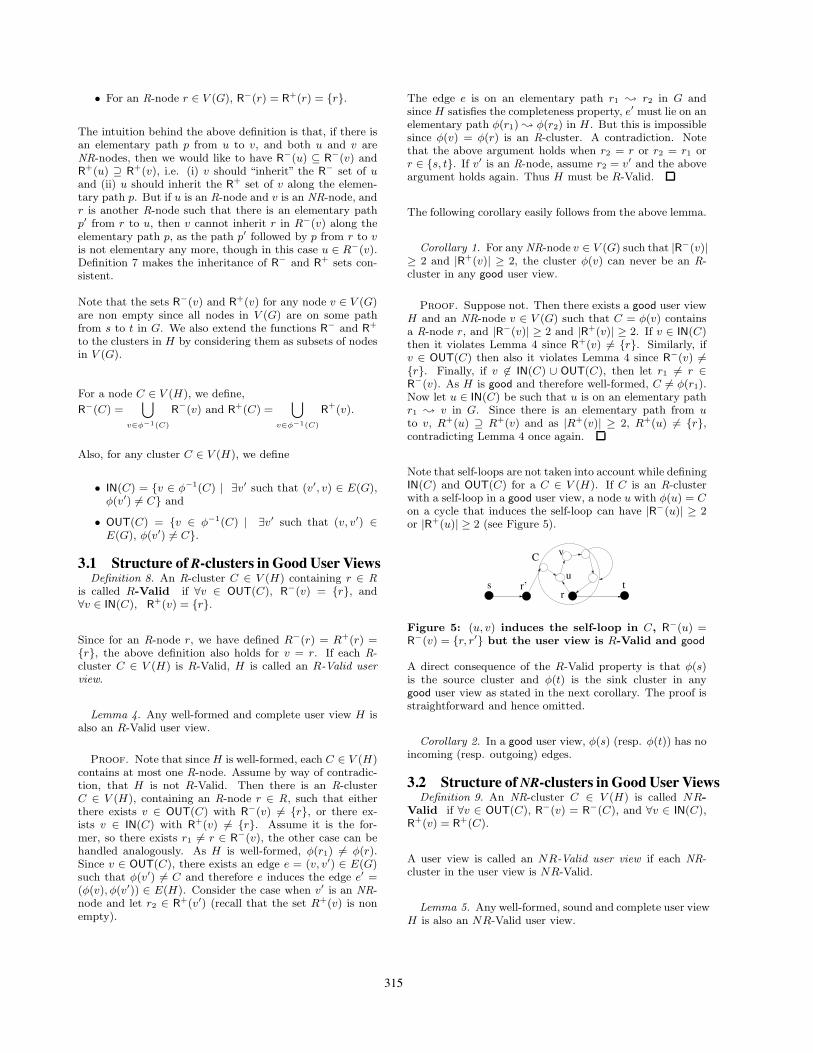
Note that self-loops are not taken into account while definingIN(C) and OUT(C) for a C ∈ V (H). If C is an R-clusterwith a self-loop in a good user view, a node u with φ(u) = Con a cycle that induces the self-loop can have |R−(u)| ≥ 2or |R+(u)| ≥ 2 (see Figure 5).
s tr’r
u
vC
Figure 5: (u, v) induces the self-loop in C, R−(u) =R−(v) = {r, r′} but the user view is R-Valid and good
A direct consequence of the R-Valid property is that φ(s)is the source cluster and φ(t) is the sink cluster in anygood user view as stated in the next corollary. The proof isstraightforward and hence omitted.
Corollary 2. In a good user view, φ(s) (resp. φ(t)) has noincoming (resp. outgoing) edges.
3.2 Structure ofNR-clusters in GoodUser ViewsDefinition 9. An NR-cluster C ∈ V (H) is called NR-
Valid if ∀v ∈ OUT(C), R−(v) = R−(C), and ∀v ∈ IN(C),R+(v) = R+(C).
A user view is called an NR-Valid user view if each NR-cluster in the user view is NR-Valid.
Lemma 5. Any well-formed, sound and complete user viewH is also an NR-Valid user view.
315
Proof. Assume by way of contradiction that H is notNR-Valid. Here we consider the case when there exists anNR-cluster C ∈ V (H) and an R-node r ∈ R−(C) such thatfor some v ∈ OUT(C), the node r "∈ R−(v) (by definition,R−(C) ⊇ R−(v)). The other case can be handled analo-gously. Since r ∈ R−(C), ∃u ∈ IN(C) such that r ∈ R−(u)and there exists an edge eu = (u′, u) on an elementary pathfrom r to u, where φ(u′) "= C. This edge induces an edgee′u = (φ(u′), C) in H . As the set R+(u) is non empty thereexists ru ∈ R+(u) and as H is complete, e′u is on an elemen-tary path pu from φ(r) to φ(ru).
Similarly, as v ∈ OUT(C), there exists an edge ev = (v, v′) ∈E(G) such that φ(v′) "= C and e induces the edge e′v =(C, φ(v′)) in H . Consider the case when v′ is an NR-nodeand r′ ∈ R+(v′). Again as R−(v) is non empty, ∃rv ∈ R−(v),rv "= r. The edge ev was on an elementary path from rv tor′ in G, so e′v is on an elementary path pv from φ(rv) toφ(r′) in the complete user view H .
Since H is well formed and rv "= r, φ(rv) "= φ(r). Theelementary paths pu (from φ(r) to φ(ru)) and pv (fromφ(rv) to φ(r′)) intersect at the cluster C and thus createsan elementary path from φ(r) to φ(r′) in H with the edgee′v = (C, φ(v′)) lying on this path. But as r /∈ R−(v), anorigin ev of e′v is not on an elementary path from r to r′.This contradicts the fact that H is a sound user view. Theabove argument also holds if any two of r, r′, ru, rv are samenode, with the restriction that r "= rv. If v′ is an R-node,consider r′ as v′ and the above argument holds once again.Thus H must be NR-Valid.
3.3 Characterization of Good User Views us-ing R-Valid and NR-Valid Properties
The following lemma gives a sufficient condition for a userview to be a good user view and therefore, in combinationwith Lemma 4 and Lemma 5, completes the characterizationof a good user view given by Theorem 2.
Lemma 6. A well-formed user view (H,φ) that is bothR-Valid and NR-Valid, is a good user view.
Proof. We start by arguing the soundness of H . Assumeby way of contradiction that H is both R-Valid and NR-Valid but it is not sound. Then there exists an edge e′ =(C, C′) ∈ E(H) and R-nodes r1, r2 ∈ R such that e′ is onan elementary path connecting cluster φ(r1) to cluster φ(r2)but an edge e = (v1, v2) ∈ E(G) that is origin of e′ is not onan elementary path from r1 to r2 in G. We will now showthat r1 ∈ R−(v1). Consider an elementary path in H fromφ(r1) to C, say, φ(r1), Ci1 , · · · , Cil , C and let this path beinduced by the edges (v+
r1, v−
i1), (v+
i1, v−
i2), · · · , (v+
il−1, v−
il),
(v+il
, v−
1 ), where v+r1
∈ OUT(φ(r1)), for j = 1 to l, v−
ij∈
IN(Cij ), v+ij
∈ OUT(Cij ) and v−
1 ∈ IN(C). Since φ(r1) is
R-Valid, r1 ∈ R−(v+r1
), an elementary path r1 ! v−
i1exists,
and therefore r1 ∈ R−(v−
i1). Also, since H is NR-Valid,
it is easy to see that r1 ∈ R−(v+i1
) as well, and therefore,
the elementary path r1 ! v+i1
exists. This elementary pathcan be extended up to v1 using the same argument and thusestablishing that r1 ∈ R−(v1). Using a similar argument, we
can show that r2 ∈ R+(v2). This contradicts the assumptionthat e = (v1, v2) is not on any elementary path from r1 tor2.
We next argue the completeness of H . Assume by way ofcontradiction that there exists an edge e ∈ E(G) on an el-ementary path p from r1 to r2, r1, r2 ∈ R, such that theedge e′ ∈ E(H) induced by e, is not on any elementarypath from φ(r1) to φ(r2) in H . Let the r1 ! r2 elementarypath p be r1, v1, · · · , vl, r2. The subgraph of H induced bythe nodes in the set {φ(r1), φ(v1), φ(v2), · · · , φ(vl), φ(r2)}must induce a path from φ(r1) to φ(r2) and let the path beφ(r1), C1, · · · , Cq, φ(r2). We will now prove that the pathφ(r1), C1, · · · , Cq , φ(r2) is elementary. For each node vi
on the path p, r1 ∈ R−(vi) and r2 ∈ R+(vi). Therefore,φ(vi) "= φ(r) for any R-node r /∈ {r1, r2}, as otherwise, weviolate the assumption that H is R-Valid. We also claim thatfor each Cj , Cj /∈ {φ(r1), φ(r2)}. If Cj = φ(r1) for some j,then there exists a v ∈ IN(Cj), with r2 ∈ R+(v), contradict-ing that Cj = φ(r1) is R-Valid. Similarly if Cj = φ(r2) forsome j, then there exists a v ∈ OUT (Cj), with r1 ∈ R−(v),again contradicting that Cj = φ(r2) is R-Valid.
Theorem 2. A well-formed user view is good if and onlyif it is both R-Valid and NR-Valid.
The significance of Theorem 2 is that it maps global con-straints on the structure of a good user view to a simplecollection of locally-testable properties.
4. SERIES-PARALLEL WORKFLOWSGiven a specification such that the underlying graph G is a(two terminal) directed SP graph, we now present an algo-rithm for finding a good user view with minimum size forG. Since the completeness and soundness properties are notaltered by the presence or absence of multiple copies of anedge, we will assume w.l.o.g. that the input graph G is asimple directed SP graph (i.e. it has no parallel edges).
4.1 The Algorithm SP-ViewWe start with an overview of the algorithm. Our algorithmprocesses the vertices in a topologically sorted order [8], mak-ing a forward and a backward pass, and incrementally buildsthe clusters in the final user view.
Definition 10. Given a directed acyclic graph G, a topo-logically sorted order (or, simply a topological order) is alinear ordering τ on V (G) such that for each edge (u, v) ∈E(G), u is listed before v in τ .
The fact that such a topological ordering exists follows fromObservation 1.
In the forward pass, if possible, Procedure SPV-Forwardmerges each newly encountered NR-node with one of the (al-ready formed) clusters which its predecessors in G belong to.We will prove that all intermediate user views in this processare directed SP graphs and are good. SPV-Forward takesG as input and outputs an intermediate SP user view H ′.
316
Algorithm 1 Algorithm SP-ViewInput: A directed SP graph GOutput: A good user view H ′′
– Run SPV-Forward on G to produce (H ′, φ′).– Run SPV-Reverse on (H ′, φ′) to produce (H ′′, φ′′).– output (H ′′, φ′′).
In the backward pass, Procedure SPV-Reverse performs amirror step. SPV-Reverse takes H ′ as input and outputsthe final user view H ′′. This algorithm is similar to SPV-Forward but processes nodes in H ′ (which are clusters ofnodes in G) in reverse topological order , i.e. merges nodeswith their successors instead of their predecessors. We alsoshow that, there is a simple linear (O(n)) time implemen-tation of SP-View and given an SP workflow graph G asinput, SP-View outputs a user view which is optimum insize for G.
Then we show that, for each NR-cluster that remains in thefinal user view H ′′, a unique R-cluster can be identified as awitness for its existence. In addition to that, each R-clusterserves as a witness of at most one NR-cluster in the finaluser view. This observation with slight care in handling ofthe boundary cases suffices to argue that the total numberof clusters in the output can not exceed 2k − 3.
A key step in these algorithms is merging two clusters C andC′ in a user view (H1, φ1) to create a new cluster C∗. Thiscreates a new user view (H2, φ2) defined as follows.
1. (Merge C and C′) ∀u ∈ V (G) if φ1(u) ∈ {C, C′}, defineφ2(u) = C∗ and add C∗ to V (H2).
2. (Keep other clusters unchanged) ∀u ∈ V (G) such thatφ1(u) $∈ {C, C′}, define φ2(u) = φ1(u). Also add eachC′′ $∈ {C, C′} to V (H2).
3. (Edge set) For each edge (u, u′) ∈ E(G), if φ2(u) $=φ2(u′), add the edge (φ2(u), φ2(u′)) to E(H2). Notethat as G is a directed SP graph and therefore is acyclicfrom Observation 1, any user view of G will not havea self-loop.
4.2 Algorithm SPV-ForwardLet v1, v2, ..., vn denote nodes of G in a topological order.Algorithm SPV-Forward proceeds iteratively, processingthe node vi of G in iteration i. At the end of an iteration i, itcreates an intermediate (good) user view (Hi, φi). It startswith (H0, φ0) where φ0 is a one-to-one mapping ∀v, φ0(v) ={v}. In iteration i, vi is considered for merging with one ofits predecessors. Upon termination, SPV-Forward returns(H ′, φ′) = (Hn, φn).
It is easy to see that in any topological order of the nodesin V (G), v1 = s and vn = t. We will show that each in-termediate user view Hi is a good user view. Hence fromCorollary 2, in each intermediate graph Hi, only φi(s) has0-indegree, and only φi(t) has 0-outdegree. Therefore, if anNR-node vi is processed in iteration i, then vi must satisfyone of the three cases (II), (III) and (IV).
Table 1: Actions taken by SPV-Forward to pro-cess an NR-node vi based on the number of R-predecessors and NR-predecessors of vi in Hi−1
Case #R-pre- #NR-pre- Actiondecessor decessor
(I) = 0 = 0 Does not arise(II) = 0 ≥ 1 Merge with the
last predecessor ina topological order
(III) = 1 = 0 Merge with thepredecessor
(IV)≥ 1 ≥ 1 Do nothing≥ 2 ≥ 0
Algorithm 2 Algorithm SPV-ForwardInput: A directed SP graph GOutput: A good SP user view (H ′, φ′)
– Let n = |V (G)|– Let (v1, v2, · · · , vn) be a topological order of vertices inV (G)for i = 1 to n do {/* H0 = G */}
– φ0(vi) = {vi}end forfor i = 1 to n do {/* φi−1(vi) = {vi} */}
if vi is an R-node then {/* do nothing */}–(Hi, φi) = (Hi−1, φi−1)
else {/* vi is an NR-node */}if φi−1(vi) has no R-predecessor in Hi−1 then {/*Case (II) */}
– Let the NR-predecessors of φi−1(vi) in Hi−1 bethe clusters C1, C2, · · · , C! listed in a topologicalorder in Hi−1
– Merge clusters C! and φi−1(vi)else if φi−1(vi) has exactly one R-predecessor and noNR-predecessor in Hi−1 then {/* Case (III) */}
– Let C be the unique predecessor of φi−1(vi) inHi−1 (and C is an R-cluster)– Merge clusters C and φi−1(vi)
else {/* Case (IV): φi−1(vi) has ≥ 2 predecessorsincluding ≥ 1 R-predecessors in Hi−1; do nothing*/}
– (Hi, φi) = (Hi−1, φi−1)end if
end ifend for– (H ′, φ′) = (Hn, φn)– output (H ′, φ′)
4.2.1 Invariants of SPV-ForwardAs mentioned earlier, SPV-Forward incrementally formsan intermediate user view processing the node vi in itera-tion i so that each intermediate user view formed satisfiessome properties. The following lemma lists a set of struc-tural properties of the user view formed at the end of eachiteration. We defer the proof to the full version of the paper.
Lemma 7. For any i ∈ [1..n], upon termination of the i-th iteration of SPV-Forward, the pair (Hi, φi) satisfies thefollowing invariants:
317
1. Hi is acyclic.
2. Hi is a directed SP-graph.
3. If φi(vi) is an NR-cluster, then φi(vi) has at leasttwo predecessors in Hi, at least one of which is anR-predecessor.
Hence, after the execution of SPV-Forward on G, we get auser view H ′ satisfying the properties given by the followingcorollary.
Corollary 3. The output graph H ′ produced by SPV-Forward is a directed SP graph. Moreover, if C is an NR-cluster in H ′, C has at least two predecessors including anR-predecessor.
4.2.2 Correctness of SPV-ForwardWe will use the characterization of a good user view givenin Theorem 2 to prove that the graph H ′ output by SPV-Forward is a good user view.
Lemma 8. After each iteration i of SPV-Forward, theintermediate graph Hi is a good user view.
Proof. We prove the lemma by induction on the numberof iterations. At i = 1, the start node s gets processed, andsince it is an R-node, H1 = H0 = G, and hence trivially is agood user view.
Now suppose that the hypothesis holds until iteration i− 1,just before the node vi is processed. If vi is an R-node or vi
is an NR-node that satisfies Case (IV), Hi = Hi−1 and weare done. Hence we need to only consider the Cases (II) and(III) for an NR-node vi. Say in these cases C = φi−1(vi) ismerged with a predecessor C′ in Hi−1 to form the clusterC∗ in Hi. Note that Hi is well-formed.
Case (II): Hi is R-Valid as no R-node is being changed. Firstconsider the case when C′ is the unique NR-predecessorof C = {vi} in Hi−1. Since C′ is NR-Valid, for all u ∈OUT(C′) the R−(u) sets are same and are equal to R−(C′).C′ is the unique predecessor of C, so for all edges (u, vi) ∈E(G), u ∈ C′ in Hi−1 and therefore, u ∈ OUT(C′). Hence
R−(vi) =⋃
(u,vi)∈E(G)
R−(u) = R−(C′). Therefore R−(C∗) =
R−(vi) ∪ R−(C′) = R−(C′). In Hi, vi /∈ IN(C∗), vi ∈OUT(C∗) and R−(vi) = R−(C∗). Hence for all u ∈ OUT(C∗),R−(u) = R−(C) = R−(C∗). Also note that R+(C∗) =R+(C′) (as ∃u ∈ C′ such that (u, vi) ∈ E, R+(C) ⊆ R+(C′),so R+(C∗) = R+(C′) ∪ R+(C) = R+(C′)). Since C′ isNR-Valid and vi /∈ IN(C∗), for all v ∈ IN(C∗), R+(v) =R+(C′) = R+(C∗). So C∗ remains NR-Valid in Hi, and asall other NR-nodes are unchanged, Hi is NR-Valid. SinceHi is well-formed, it is a good user view.
Now we consider the case when C = {vi} has " > 1 NR-predecessors C1, · · · , C!, listed in the topological order ofclusters in Hi−1 and C is merged with C! to form C∗ inHi. From Invariant 2 of Lemma 7 Hi−1 is a directed SPgraph, hence from Lemma 3 C is the unique successor of
C!. Therefore, for each u ∈ OUT(C!), (u, v) ∈ E(G) withv /∈ C! if and only if v = vi. Hence in Hi, OUT(C∗) ={vi} and IN(C∗) = {vi} ∪ IN(C!). Since OUT(C∗) = {vi},∀v ∈ C∗, R+(v) = R+(vi) = R+(C∗). Therefore ∀v ∈IN(C∗), R+(v) = R+(C∗). Again as OUT(C∗) = {vi},
R−(vi) =⋃
v∈C∗
R−(v) = R−(C∗). These two facts to-
gether imply that C∗ is NR-Valid. All other NR-nodes areunchanged in Hi. Hence Hi is NR-Valid.
Case (III): Here C′ is the unique R-predecessor of C. SinceHi−1 is a good user view, each R-cluster in Hi−1 is R-Validand each NR-cluster is NR-Valid. Now all NR-clusters ex-cept the singleton cluster C = {vi} are unchanged in Hi, andC is merged with an R-cluster in Hi. Therefore, R− and R+
sets of all NR-clusters remain unchanged in Hi (recall thatR− and R+ sets of a cluster are defined over the specifica-tion graph G) and Hi is NR-Valid. Now we show that C∗
is R-Valid. Since Hi−1 is a good user view, R-cluster C′ inHi−1 is R-Valid. Let r ∈ R be the unique R-node in C′ (asHi−1 is good, it is well-formed). Since C′ is the unique pre-decessor of C = {vi} in Hi−1, for all edges (u, vi) ∈ E(G),u ∈ C′ in Hi−1, and therefore, u ∈ OUT(C′). Since C′
is R-Valid, R−(u) = {r}, and therefore R−(vi) = {r}. InHi, vi ∈ OUT(C∗) (because vi is an NR-node, vi '= sinknode t ∈ V (G), and vi can not have 0 outdegree), andR−(u) = {r}. For all other nodes u ∈ OUT(C∗) in Hi,R−(u) = {r} and for all nodes v ∈ IN(C′), v ∈ IN(C∗),hence R+(v) = {r} (note that vi /∈ IN(C∗)). So C∗ remainsR-Valid in Hi. So Hi is both R-Valid and NR-Valid, andit is well-formed. Hence from Theorem 2, Hi is a good userview.
Hence after the execution of SPV-Forward, we have a gooduser view as stated in the following corollary.
Corollary 4. H ′ is a directed SP graph that is a good userview of the input specification graph G.
4.3 Algorithm SPV-ReverseSPV-Reverse takes the intermediate user view (H ′, φ′) asinput, and performs the merging process of SPV-Forwardon a reverse topological order of the clusters in H ′. Moreprecisely, we can view SPV-Reverse as reversing the di-rection of all edges in H ′ and running SPV-Forward onthis reversed copy of H ′. Thus SPV-Reverse attempts tomerge a cluster in H ′ with one of its successor instead of itspredecessors.
It can be verified that the property of an NR-cluster of graphH ′ given by Invariant 3 is not destroyed by SPV-Reverse.Assume that C∗ = {Cip , Cip−1
, · · · , Ci1} is an NR-clusterin H ′′ where Cip , Cip−1
, · · · , Ci1 are NR-clusters of H ′ andthey entered C∗ in the order ip, ip−1, · · · , i1. From Corol-lary 3, Ci1 had two predecessors including an R-predecessor.If Ci1 had two R-predecessors in H ′, they will form two R-clusters in H ′′ (as H ′′ is well-formed), and the property willhold in H ′′. Otherwise, Ci1 had at least one NR-predecessor,say Cnr, and an R-predecessor, say Cr in H ′. As Ci1 is thelast cluster of H ′ added in C∗, Cnr is not included in C∗
and hence must belong to an NR-cluster C∗nr in H ′′ (note
318
that Cnr can not be merged with one of its R-successor asCi1 is one of its NR-successor in H ′). The R-predecessor Cr
of Ci1 will form an R-cluster, say C∗r in H ′ and will be a
predecessor of C∗. Hence the cluster C∗ in H ′′ will have atleast one R-predecessor C∗
r and at least one NR-predecessorC∗
nr.
Thus using Corollary 3 and Lemma 8, we can conclude thefollowing.
Lemma 9. The output graph H ′′ produced by SP-Viewis a directed SP graph. Moreover, if C is an NR-clusterin H ′′, C has at least two predecessors including an R-predecessor and at least two successors including an R-successor.
The correctness proof of SPV-Forward on G as done inLemma 8, along with the R-Valid and NR-Valid propertiesof the clusters in H ′, can also be extended to SPV-Reverse,which runs SPV-Forward on the “reverse” of H ′. Combin-ing all these, the next theorem follows.
Theorem 3. H ′′ is a two terminal directed SP graph thatis a good user view of the input specification graph G.
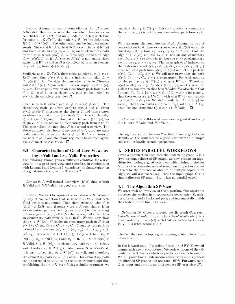
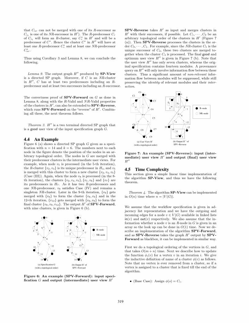
4.4 An ExampleFigure 6 (a) shows a directed SP graph G given as a speci-fication with n = 14 and k = 6. The numbers next to eachnode in the figure denote the position of the nodes in an ar-bitrary topological order. The nodes in G are merged withtheir predecessor clusters in the intermediate user views. Forexample, when node v5 is processed (in the 5-th iteration),the R-cluster {v2, v4} is its unique predecessor in H4, and v5
is merged with this cluster to form a new cluster {v2, v4, v5}(Case (III)). Again, when the node v8 is processed (in the 8-th iteration), the clusters {v2, v4, v5}, {v1, v6} and {v7} areits predecessors in H7. As it has two R-predecessors andone NR-predecessor, v8 satisfies Case (IV) and remains asingleton NR-cluster. Later in the 9-th iteration, {v9} getsmerged with {v8} to form the cluster {v8, v9} and in the12-th iteration, {v12} gets merged with {v8, v9} to form thefinal cluster {v8, v9, v12}. The output H ′ of SPV-Forward,with nine clusters, is given in Figure 6 (b).
1s
t
1
2 3
45
6
7
89
10
11
12
13
14
s
t
3
47
1013
14
SPV!Forward(with a topological order)(a) Specification G (b) Output H’ of
R!node
NR!node
2
5
6
98
12
11
Figure 6: An example (SPV-Forward): input speci-fication G and output (intermediate) user view H ′
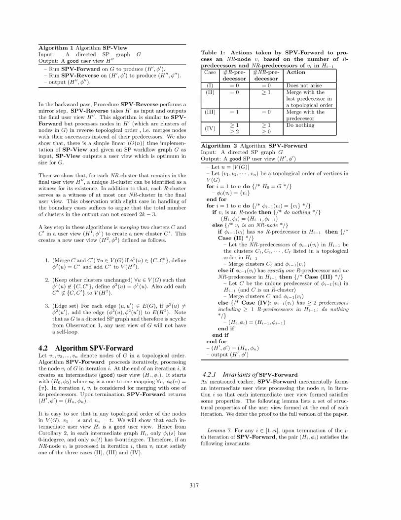
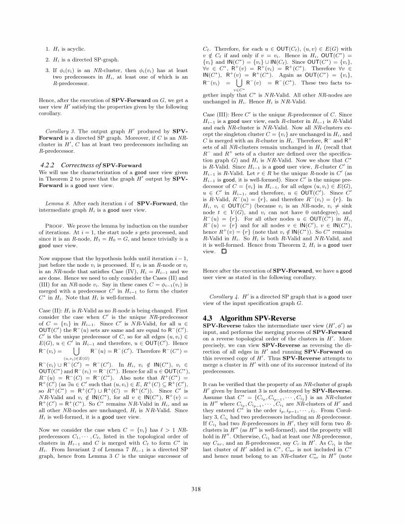
SPV-Reverse takes H ′ as input and merges clusters inH ′ with their successors, if possible. Let C1, · · · , C9 be anarbitrary topological order of the clusters in H ′ (Figure 7(a)). Then SPV-Reverse processes the clusters in the or-der C9, · · · , C1. For example, since the NR-cluster C5 is theunique successor of C4, these two clusters are merged to-gether when the cluster C4 is processed. The final good andoptimum user view H ′′ is given in Figure 7 (b). Note thatthe user view H ′′ has only seven clusters, whereas the orig-inal specification contains fourteen modules. A provenancequery on H ′′ will only involve information flow between theseclusters. Thus a significant amount of non-relevant infor-mation flow between modules will be suppressed, while stillpreserving the identity of relevant modules and their inter-action.
12
R!node
NR!node
(with a topological order)
s
t(a) User View H’
C1C2
C3
C4
C5
C6
C8 C7
C9
s
t
2 3
13
14
(b) Output H’’ ofSPV!Reverse
8
4
5
6
1
7
9
10
11
Figure 7: An example (SPV-Reverse): input (inter-mediate) user view H ′ and output (final) user viewH ′′
4.5 Time ComplexityThis section gives a simple linear time implementation ofthe algorithm SP-View, and thus we have the followingtheorem.
Theorem 4. The algorithm SP-View can be implementedin O(n) time where n = |V (G)|.
We assume that the workflow specification is given in ad-jacency list representation and we have the outgoing andincoming edges for a node v ∈ V (G) available in linked listsin(v) and out(v) respectively. We also assume that the in-formation whether a node v is an R-node in G is given in anarray so the look up can be done in O(1) time. Now we de-scribe an implementation of the algorithm SPV-Forward,and as SPV-Reverse takes the graph H ′ output by SPV-Forward as blackbox, it can be implemented in similar way.
First we do a topological ordering of the vertices in G, andthat takes O(m + n) time. Next we describe how to updatethe function φi(v) for a vertex v in an iteration i. We givethe inductive definition of name of a cluster φ(v) as follows.Note that no vertex is ever removed from a cluster, so if avertex is assigned to a cluster that is fixed till the end of thealgorithm.
• (Base Case): Assign φ(s) = C1.
319
• (Iteration i): Let C1, · · · , Cj−1 be the clusters allo-cated so far till iteration i−1. If the node processed initeration i is not merged with any predecessor, allocatea new cluster Cj and assign φ(vi) = Cj .
Otherwise, if vi is merged with a predecessor clusterCj1 , assign φ(vi) = Cj1 .
We claim that as the vis are listed in topological order, theclusters Cjs as they are being allocated, are always listedin topological order. If a node vi is assigned a new single-ton cluster Cj (i.e. not merged with any predecessor), thentopological order of the clusters is not violated as vi can nothave an edge to a previously allocated cluster Cj1 , j1 < j.Same is the case when vi is merged with its unique prede-cessor cluster in Hi−1. If vi has ≥ 2 NR-predecessors andno R-predecessor, we will merge vi with the predecessor Cj1
with the highest index j1, and again the topological order ofthe clusters remains maintained.
We also keep track of whether a cluster Cj is an R-cluster orNR-cluster by updating this information each time a nodeenters the cluster. For a vertex v, the function φ(v) canbe computed as follows. If v = vi is processed in iterationi, we go over the list in(v). If we find all u ∈ in(v) havesame φ(u), we know that v has unique predecessor in Gi−1
(that may be an R-cluster or an NR-cluster). If not, butfor all the u ∈ in(v), φ(u) are NR-clusters, we compute thehighest index " such that for an u ∈ in(v), φ(u) = C! andassign φ(vi) = C!. This way we find the last predecessorin a topological order in Hi−1. Otherwise we know thatvi has at least two predecessors in Gi−1 including one R-cluster and we allocate new Cj for φ(vi). Note that fora vertex v, the function φ(v) can be computed in time =O(|in(v)|). Hence total time complexity for all the iterations
is max(n,∑
v∈V (G)
(O(|in(v)|) = O(m + n). Finally we output
the graph H ′ by going over all v ∈ V (G) and looking atφ(v) to build the sets in(C) and out(C) for each cluster C inV (H ′), which will be the input for SPV-Reverse. Againit can be done in O(m + n) time. Hence the algorithm SP-View can be implemented in O(m +n) time which is linearin terms of the size of the input graph G. Since for an SPgraph, m = O(n), the overall time complexity is O(n), thatis, linear in the size of V (G).
4.6 Optimality of the Algorithm SP-ViewIn this section we show that the number of clusters in anygood user view is as large as the number of clusters in H ′′,i.e. we prove the following theorem.
Theorem 5. For a given specification (G, s, t,R) where Gis a two terminal directed SP graph, the user view (H ′′, φ′′)output by Algorithm SP-View is optimum in size.
Here we will give an overview of the proof and state themain lemmas, and defer the details to the full version of thepaper.
Overview of the Proof:. Suppose the output user view H ′′
contains Nr = k R-clusters and Nnr NR-clusters. As any
good user view H is well-formed, it has to contain Nr R-clusters. Hence it suffices to prove that any good user viewalso has at least Nnr NR-clusters.
Let us recall from Corollary 1 that if an NR-node v is suchthat |R−(v)| ≥ 2 and |R+(v)| ≥ 2 then v cannot be includedin an R-cluster in any good user view. We will call these NR-nodes as Essential NR-nodes, that must be in NR-clusters inany good user view.
Definition 11. An NR-node v is called Essential if |R−(v)| ≥2 and |R+(v)| ≥ 2.
First we show that each NR-cluster in H ′′ contains at leastone Essential NR-node. Then we deduce a sufficient condi-tion when two Essential NR-nodes vi, vj , are included in thesame NR-cluster in H ′′ by SP-View. Finally we show thatwhen two Essential NR-nodes vi, vj are put in different NR-clusters by SP-View, then no good user view can put vi, vj
in the same NR-cluster. In particular, if C1 and C2 are twodistinct NR-clusters of H ′′, then an Essential NR-node fromC1 and an Essential NR-node from C2 can never be includedin the same NR-cluster in any good user view. This willcomplete the proof of Theorem 5.
(1) Existence of Essential nodes in each NR-cluster inH ′′:. For an NR-node v, we will prove that if φ′(v) is anNR-cluster in H ′, then |R−(v)| ≥ 2. Similarly, if C is an NR-cluster in H ′′, |R+(C)| ≥ 2. As H ′′ is good, any NR-clusterC is NR-Valid, hence for all v ∈ IN(C), R+(v) = R+(C).Hence for any v ∈ IN(C), |R+(v)| ≥ 2. If φ′′(v) = C is anNR-cluster, φ′(v) is also an NR-cluster, therefore |R−(v)| ≥2. Hence, for each NR-cluster C in H ′′, there is an NR-nodev such that |R−(v)| ≥ 2 and R+(v) ≥ 2.
Lemma 10. Each NR-cluster C in H ′′ contains at leastone Essential NR-node.
(2) A sufficient condition for φ′′(vi) = φ′′(vj), wherevi, vj are two Essential NR-nodes. The following lemmagives a sufficient condition.
Lemma 11. For two Essential NR-nodes vi, vj , if (i) R−(vi) =R−(vj) or R+(vi) = R+(vj), or, (ii) there exists a vi ! vj
path and all paths from vi to vj are elementary paths, thenφ′′(vi) = φ′′(vj).
Lemma 11 will be proved in two steps. First we will provethat for two Essential nodes vi, vj , if R−(vi) = R−(vj) orR+(vi) = R+(vj), then φ′′(vi) = φ′′(vj). Next we will showthat if a vi ! vj path exists and all paths from vi to vj
are elementary paths, then there exists an NR-node v! suchthat both R−(v!) = R−(vj) and R+(vi) = R+(v!) hold.Combining these two facts Lemma 11 will be proved.
(3) The number of NR-clusters in H ′′ is optimum:. Tocomplete the proof of optimality of the algorithm, for two
320
Essential NR-nodes vi, vj , we will show that if (i) there is anyR-node on any path from vi to vj , or (ii) R−(vi) != R−(vj)and R+(vi) != R+(vj) and no vi to vj path exists, then vi andvj cannot be included in the same NR-cluster in any gooduser view. Combining the above observation with Lemma 11the next lemma proving the optimality of SP-View follows.
Lemma 12. For two Essential NR-nodes vi, vj , if φ′′(vi) !=φ′′(vj) then no good user view can put vi, vj in the sameNR-cluster.
Thus the number of NR-clusters in H ′′ cannot be reducedin any good user view and the user view H ′′ output by SP-View is optimum in size.
4.7 Extremal Bounds on Size of a Good UserView for SP Graphs
We now give tight extremal bounds on the size of good userviews when the specification graph is an SP graph. We showthat, whatever be the total number of nodes n, the size ofH ′′ output by SP-View is at most 2k − 3, and there existSP graphs which always require 2k − 3 clusters in a gooduser view.
4.7.1 An Upper Bound on the Size of a good UserView for SP Graphs
First we show that if there is an NR-cluster C in the finaluser view H ′′ by the algorithm SP-View, there is an R-predecessor of C which “accounts for” the existence of C inH ′′. The following lemma will be used in proving the upperbound; the proof is deferred to the full version.
Lemma 13. Let C ∈ V (H ′′) be an NR-cluster. Then inany topological order of the clusters in V (H ′′), the last pre-decessor C′ of C is an R-cluster and C is the unique successorof C′ in H ′′.
The following corollary immediately follows from Lemma 13.
Corollary 5. In H ′′, each NR-cluster C ∈ V (H ′′) has atleast one R-predecessor C′ such that C is the unique succes-sor of C′ in H ′′.
Note that since s, t ∈ R, k ≥ 2, and therefore any good userview must contain at least 2 clusters. Next we show that|V (H ′′)| ≤ 2k − 3, thereby proving the following theorem.
Theorem 6. Given a workflow specification (G, s, t,R) whereG is a directed SP graph, there exists a good user view ofsize at most 2k−3 that is also a directed SP graph, wheneverk = |R| ≥ 3.
Proof. We will show this by a simple “charging argu-ment” on the good user view H ′′ by our algorithm. If thenumber of NR-clusters in H ′′ is 0, then the upper bound of2k − 3 trivially holds because 2k − 3 ≥ k for k ≥ 3. Other-wise, let C1, C2, · · · , C! be the NR-clusters in H ′′, listed in
the topological order for some " ≥ 1. We start with an initialassignment of a charge of 1 to each R-cluster. The analysisabove shows that this charge assignment, a total of k units,suffices to account for all NR-clusters. We will show thatthis charge can be reduced to k − 3 and still all NR-clusterswill get accounted for, proving the desired bound. This isachieved by noting that Lemma 9 requires the cluster C1
to have at least two predecessors. But each predecessor ofC1 must be necessarily an R-predecessor as C1 is the firstNR-cluster in the topological sorted order. We argue thatthese R-predecessors of C1 are not charged by any other NR-cluster. This is because if C1 is the single NR-successor ofthese clusters, we are done. If an R-predecessor Cr of C hasanother NR-successor C′
1 != C1, by Corollary 5, C′1 has one
R-predecessor C′r != Cr, such that C′
1 is unique NR-successorof C′
r, and therefore C′r is charged for the existence of C′
1.Thus we can drop the charge on one of these two clustersand still account for all NR-clusters. Similarly, C! must haveat least two R-successors such that neither of them is an R-predecessor of any NR-cluster. We can drop the charge onboth of these clusters. Thus the total remaining charge onR-clusters is exactly k− 3, proving that the total number ofclusters in H ′′ is at most 2k − 3.
4.7.2 A Lower Bound on the Size of a good User Viewfor SP Graphs
In this section we show that the upper bound given in The-orem 6 for directed SP graphs is tight.
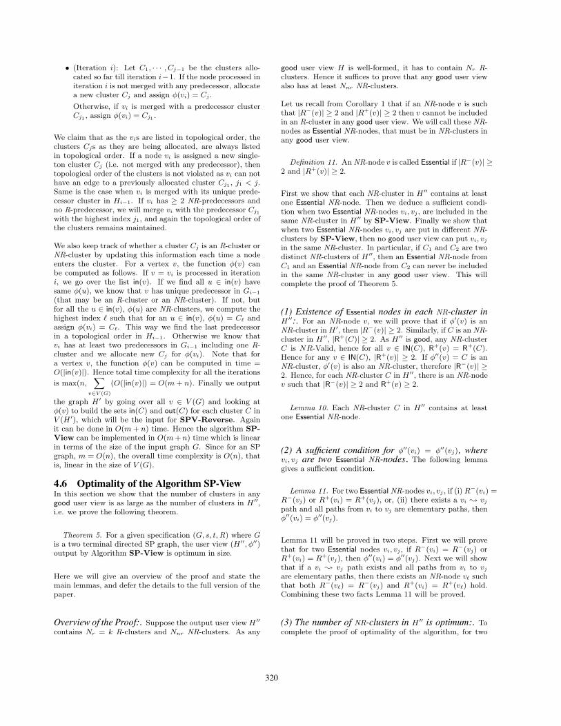
Theorem 7. There is a directed SP graph Hk with k R-nodes that needs exactly 2k−3 nodes in any good user view.
The example graph Hk with 2k−3 nodes is given in Figure 8where the ri’s are R-nodes and nrj ’s are NR-nodes. It is easy
nr 1 nr 2r 0s =
r 1 r2 rk!13 rk!2
nr k!3nrk!4 t= r k!1
Figure 8: SP graph Hk that needs 2k − 3 clusters
to see that no two nodes in this graph can be included inthe same cluster in any good user view, hence we omit theproof.
5. GENERAL GRAPHSIn this section we give an upper bound on the number of clus-ters for the general graph model using the ZOOM algorithmgiven in [2]. The upper bound we get is an (exponential)function of number of relevant modules k and is indepen-dent of n (the total number of modules in the specification).We also show that our upper bound is tight, i.e., there ex-ist graphs that need exponentially many nodes in any gooduser view. However, given a general graph as a specifica-tion, the question of whether there exists a polynomial timealgorithm for constructing an optimum user view is an openproblem.
Given any graph G, the algorithm in [2] can be described asfollows in terms of our notations.
321
1. If for an NR-node v, R−(v) = {r} or R+(v) = {r}, vand r are put in the same cluster.
2. For an NR-node v and an NR-cluster C (after Step 1),if R−(C) = R−(v) and R+(C) = R+(v), merge C andv in the same cluster. Repeat Step 2 until no moremerging is possible.
3. (To make the user view minimal) For two NR-clustersC1 and C2 after Step 2, let C = C1 ∪ C2. If ∀v ∈OUT(C), R−(v) = R−(C) and ∀v ∈ IN(C), R+(v) =R+(C), merge C1 and C2 in the user view. RepeatStep 3 until no more merging is possible.
For simplicity, we also assume that NR-nodes can be mergedwith s and t.
5.1 Upper bound on Size of Good User ViewThe following theorem shows that for general directed graphsthere exists a good user view whose size is a function of k(and not of n); moreover, this good user view can be com-puted in polynomial time using the ZOOM algorithm.
Theorem 8. For a workflow specification (G, s, t,R), withk = |R|, the ZOOM algorithm [2] outputs a good user viewwith size ≤ (2k−1 − k)2 + k.
Proof. We look at the good user view output by theZOOM algorithm on G. Since in the specification only scan have 0-indegree and only t can have 0-outdegree, for allNR-nodes in G, the R− and R+ sets are non empty. Sincethe ZOOM algorithm merges an NR-node with its uniqueR-predecessor or its unique R-successor in Step 1, each NR-node v which is not in a cluster with some R-node after Step1 has |R−(v)| ≥ 2 and |R+(v)| ≥ 2. Also note that for anyNR-node v ∈ V (G), s /∈ R+(v) and t /∈ R−(v), and therefore,|R−(v)|, |R+(v)| ≤ k − 1. Step 2 puts NR-nodes with thesame R− and R+ clusters in same cluster. The number ofdistinct pairs (R−, R+) such that 2 ≤ |R−| ≤ k − 1 and2 ≤ |R+| ≤ k − 1 is (2k−1 − 1 − (k − 1))2. Step 3 doesfurther minimalization if possible. Taking into account theR-clusters in the user view, the total number of clustersoutput by the algorithm is therefore bounded by (2k−1−1−(k − 1))2 + k.
5.2 Lower bound on Size of Good User viewWe prove that the upper bound given by Theorem 8 is tightby constructing an example specification graph with k R-nodes such that any good user view for G will have at least(2k−1 − k)2 + k clusters.
Theorem 9. There exists a workflow specification (G, s, t,R),with k = |R|, such that number of clusters in any good userview is exactly (2k−1 − k)2 + k.
Proof. We construct a specification as follows. Labelthe R-nodes in G as r1, · · · , rk, where r1 = s and rk =t. Let v1, v2, ..., vN be the NR-nodes in G (the value of Nwill be computed later). Let P (resp. S) be the set of allpossible subsets of size ∈ [2, k − 1] of {r1, · · · , rk−1} (resp.
{r2, · · · , rk}). Now form all possible pairs (X, Y ), X ∈P, Y ∈ S, and make a one-to-one assignment between thepairs (X, Y ) and NR-nodes vi, and create the edges suchthat R−(vi) = X and R+(vi) = Y . Note that X and Y canbe same set for some vi. As |P | = |S| = (2k−1 − 1 − (k −1)) = (2k−1 − k) and the number of distinct pairs (X, Y )is (2k−1 − k)2 = N . To make this construction a feasibleworkflow specification (i.e. to keep all the nodes in V (G)on some path from s to t), we also add the edges {(r1, ri) |2 ≤ i ≤ k − 2} and {(ri, rk−1) | 2 ≤ i ≤ k − 2} to E.
For each vi, |R−(vi)| ≥ 2 and |R+(vi)| ≥ 2 - by Corol-lary 1 they can not be put together in an R-cluster. Ifvi1 , vi2 , · · · , vi! are put in the same cluster C, then eachvij ∈ IN(C) and each vij ∈ OUT(C). Since no two ofthe vij s have both of R− and R+ sets same, C is not NR-Valid and the user view would not be good (from Theo-rem 2). Hence the number of clusters in any good user viewis |V (G)| = N + k = (2k−1 − k)2 + k.
6. COMPARISONOFSP-VIEWANDZOOMON SERIES-PARALLEL GRAPHS
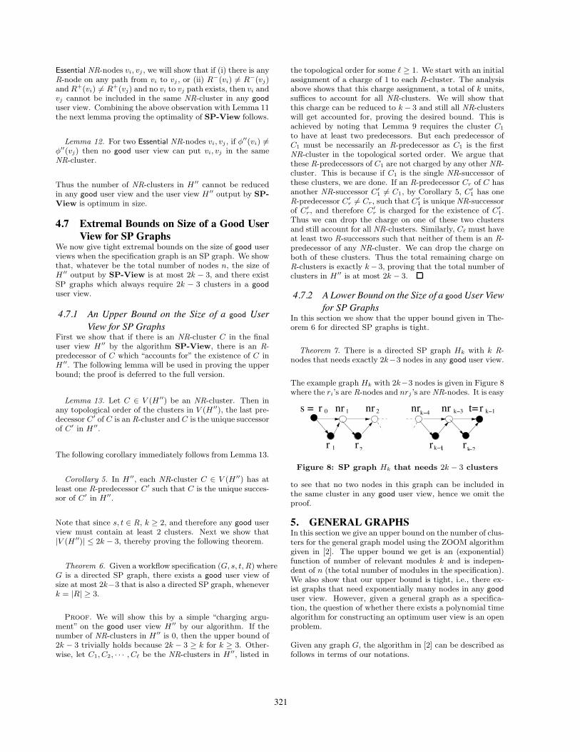
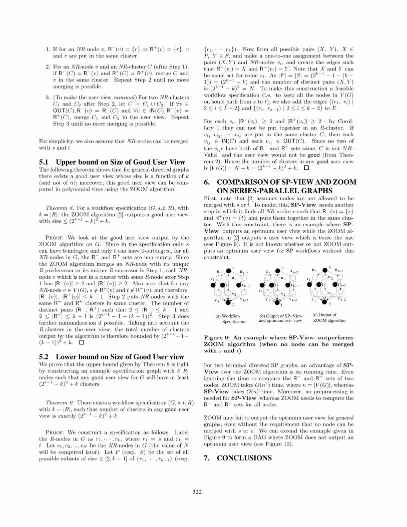
First, note that [2] assumes nodes are not allowed to bemerged with s or t. To model this, SP-View needs anotherstep in which it finds all NR-nodes v such that R−(v) = {s}and R+(v) = {t} and puts them together in the same clus-ter. With this constraint, there is an example where SP-View outputs an optimum user view while the ZOOM al-gorithm in [2] outputs a user view which is twice the size(see Figure 9). It is not known whether or not ZOOM out-puts an optimum user view for SP workflows without thisconstraint.
ZOOM algorithm
2
2v
r2 r k!2
u 2
2v
r2 r k!2
u 2
2v
r2 r k!2
u 1 u k!2
v k!21v
r1
u k!2u 1
r1
1v v k!2
u 1
r1
1v v k!2
u k!2s
(a) Workflow Specification
(b) Output of SP!Viewand optimum user view
s s
t t t
(c) Output of
u
Figure 9: An example where SP-View outperformsZOOM algorithm (when no node can be mergedwith s and t)
For two terminal directed SP graphs, an advantage of SP-View over the ZOOM algorithm is its running time. Evenignoring the time to compare the R− and R+ sets of twonodes, ZOOM takes O(n2) time, where n = |V (G)|, whereasSP-View takes O(n) time. Moreover, no preprocessing isneeded for SP-View whereas ZOOM needs to compute theR− and R+ sets for all nodes.
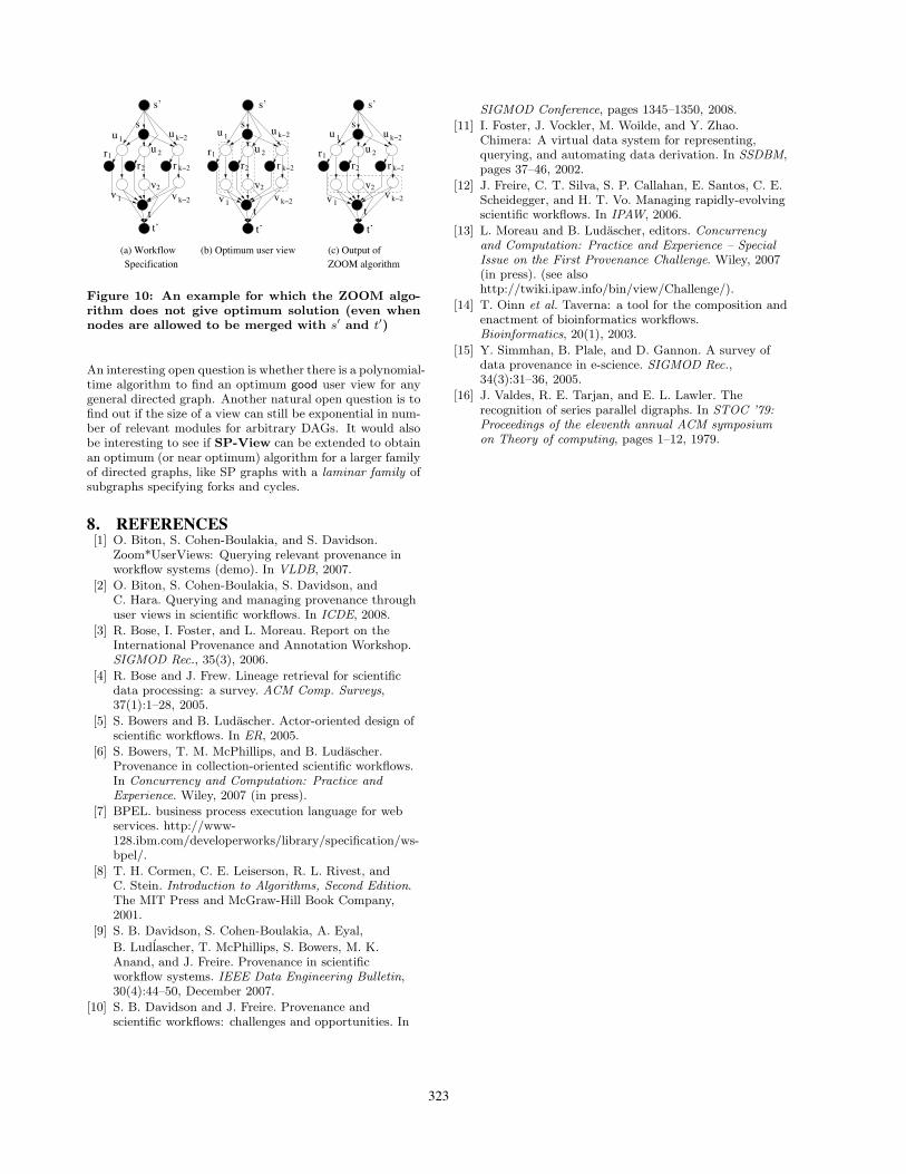
ZOOM may fail to output the optimum user view for generalgraphs, even without the requirement that no node can bemerged with s or t. We can extend the example given inFigure 9 to form a DAG where ZOOM does not output anoptimum user view (see Figure 10).
7. CONCLUSIONS
322
ZOOM algorithm
2
2v
r2 r k!2
u 1
r1
1v v k!2
u k!2u 2
2v
r2 r k!2
u k!2
v k!21v
u 1
r1
s
tt’
s’
u 2
2v
r2 r k!2
u 1 u k!2
v k!21v
r1
s
t’
s’
t
s
tt’
s’
(a) WorkflowSpecification
(b) Optimum user view (c) Output of
u
Figure 10: An example for which the ZOOM algo-rithm does not give optimum solution (even whennodes are allowed to be merged with s′ and t′)
An interesting open question is whether there is a polynomial-time algorithm to find an optimum good user view for anygeneral directed graph. Another natural open question is tofind out if the size of a view can still be exponential in num-ber of relevant modules for arbitrary DAGs. It would alsobe interesting to see if SP-View can be extended to obtainan optimum (or near optimum) algorithm for a larger familyof directed graphs, like SP graphs with a laminar family ofsubgraphs specifying forks and cycles.
8. REFERENCES[1] O. Biton, S. Cohen-Boulakia, and S. Davidson.
Zoom*UserViews: Querying relevant provenance inworkflow systems (demo). In VLDB, 2007.
[2] O. Biton, S. Cohen-Boulakia, S. Davidson, andC. Hara. Querying and managing provenance throughuser views in scientific workflows. In ICDE, 2008.
[3] R. Bose, I. Foster, and L. Moreau. Report on theInternational Provenance and Annotation Workshop.SIGMOD Rec., 35(3), 2006.
[4] R. Bose and J. Frew. Lineage retrieval for scientificdata processing: a survey. ACM Comp. Surveys,37(1):1–28, 2005.
[5] S. Bowers and B. Ludascher. Actor-oriented design ofscientific workflows. In ER, 2005.
[6] S. Bowers, T. M. McPhillips, and B. Ludascher.Provenance in collection-oriented scientific workflows.In Concurrency and Computation: Practice andExperience. Wiley, 2007 (in press).
[7] BPEL. business process execution language for webservices. http://www-128.ibm.com/developerworks/library/specification/ws-bpel/.
[8] T. H. Cormen, C. E. Leiserson, R. L. Rivest, andC. Stein. Introduction to Algorithms, Second Edition.The MIT Press and McGraw-Hill Book Company,2001.
[9] S. B. Davidson, S. Cohen-Boulakia, A. Eyal,B. Ludlascher, T. McPhillips, S. Bowers, M. K.Anand, and J. Freire. Provenance in scientificworkflow systems. IEEE Data Engineering Bulletin,30(4):44–50, December 2007.
[10] S. B. Davidson and J. Freire. Provenance andscientific workflows: challenges and opportunities. In
SIGMOD Conference, pages 1345–1350, 2008.[11] I. Foster, J. Vockler, M. Woilde, and Y. Zhao.
Chimera: A virtual data system for representing,querying, and automating data derivation. In SSDBM,pages 37–46, 2002.
[12] J. Freire, C. T. Silva, S. P. Callahan, E. Santos, C. E.Scheidegger, and H. T. Vo. Managing rapidly-evolvingscientific workflows. In IPAW, 2006.
[13] L. Moreau and B. Ludascher, editors. Concurrencyand Computation: Practice and Experience – SpecialIssue on the First Provenance Challenge. Wiley, 2007(in press). (see alsohttp://twiki.ipaw.info/bin/view/Challenge/).
[14] T. Oinn et al. Taverna: a tool for the composition andenactment of bioinformatics workflows.Bioinformatics, 20(1), 2003.
[15] Y. Simmhan, B. Plale, and D. Gannon. A survey ofdata provenance in e-science. SIGMOD Rec.,34(3):31–36, 2005.
[16] J. Valdes, R. E. Tarjan, and E. L. Lawler. Therecognition of series parallel digraphs. In STOC ’79:Proceedings of the eleventh annual ACM symposiumon Theory of computing, pages 1–12, 1979.
323