Embed Size (px)
Citation preview
Optimized Element Positions for Prescribed RadarCross Section Pattern of Linear Dipole Arrays
Shuai Zhang, Shu-Xi Gong, Ying Guan, Bao Lu
National Key Laboratory of Antennas and Microwave Technology, Xidian University,Xi’an, Shaanxi Province 710071, People’s Republic of China
Received 1 March 2011; accepted 13 May 2011
ABSTRACT: Approximate closed-form expression is derived for the scattering from dipole
arrays based on the equivalent circuit theory. Then, a method is proposed for synthesis of
dipole arrays to produce desired scattering pattern using genetic algorithm (GA). In the
synthesis method, the element positions in an array are considered as the optimization
parameter and the derived expression is used to evaluate the fitness function of GA. To assess
the validity and efficiency of the proposed method, several linear dipole arrays are designed to
obtain scattering pattern with low sidelobe level (SLL). A good agreement between the pat-
terns calculated using the expression and simulated by FEKO validates the accuracy of the
presented expression. In addition, the numerical results show that the maximum SLL of the
scattering pattern is considerably reduced by optimization. VC 2011 Wiley Periodicals, Inc. Int J
RF and Microwave CAE 21:622–628, 2011.
Keywords: antenna arrays; dipole antennas; nonuniformly spaced arrays; scattering; radar cross
section
I. INTRODUCTION
Although extensive work has been done with regard to
dipoles scattering analysis and calculation, it is rare to
find published reports describing synthesis of desired scat-
tering pattern. In most of applications, it is found that the
field scattered by the dipoles cause interference or produce
unwanted radar return. Hence, there is a need for a
method to synthesize prescribed scattering pattern of
dipole antenna arrays.
Coe and Ishimaru [1] presented a method for produc-
ing a prescribed zero in the bistatic scattering pattern of
linear dipole array by optimizing the parameters of a net-
work connected to the antenna terminals. However, this
method might not be used to automatically control the ra-
dar cross section (RCS) levels of the main lobe and the
sidelobes. To overcome this problem, in a way the similar
to the radiation pattern multiplication method [2], Lu
et al. [3] indicated that the RCS of an array can also be
expressed as the product of an array factor and an element
factor. Then, based on the expression in Ref. 3, a method
was presented in Ref. 4 for synthesizing desired scattering
pattern by adjusting the dipole positions. However, this
method does not fully consider the mutual coupling
effects. Thus, the main aim of this article is to present an
accurate and efficient method for synthesis of desired scat-
tering pattern of dipoles.
Since the electromagnetic scattering is essentially a
re-radiation problem, the method for synthesizing radia-
tion pattern may be extended to the scattering problem.
Consequently, the methods for synthesis of desired radia-
tion pattern are reviewed here.
To block the interference from the sidelobes, many
researchers have focused their aims on minimizing the
maximum side lobe level (SLL) of the radiation pattern of
an array with evolutionary methods [5–10]. Classically,
using the well-known array radiation pattern multiplica-
tion method [2] to evaluate the fitness function of the
optimization algorithm, the subject can be achieved by
optimizing the element positions [6, 7], the excitation
phases or amplitudes [8, 9]. Obtained in this case, how-
ever, the works did not fully consider the mutual coupling
effects. To solve this problem, some researchers [9–12]
proposed to combine the optimization algorithm with a
numerical method and apply the numerical method to
evaluate the fitness function. In Ref. 9, differential evolu-
tion algorithm was used to optimize the amplitude weights
of elements to drive down the sidelobes, and the method
Correspondence to: S. Zhang; e-mail: [email protected]
VC 2011 Wiley Periodicals, Inc.
DOI 10.1002/mmce.20556Published online 26 September 2011 in Wiley Online Library
(wileyonlinelibrary.com).
622

of moments (MoM) [2] was used to evaluate the fitness
function. Similarly, Haupt and Aten [10] presented a
method for synthesizing low SLL radiation pattern of
dipole arrays, in which genetic algorithm (GA) was used
to call a fitness function evaluated by MoM. Although can
offer good accuracy, they can only be applied to small
arrays due to their large computation memory space and
time requirements. For larger arrays, on the order of tens
or hundreds of elements, even the most efficient hybrid
method (those combined an optimization method with a
numerical method) may still be infeasible. In this case, it
might prove fruitful to invoke approximate methods to
evaluate the fitness function to reduce the analysis time.
To this end, based on the equivalent circuit theory [13],
the element-by-element analysis technique [14, 15] was
proposed to calculate the radiation field of dipole arrays.
In this method, the elements of the impedance matrix are
self and mutual impedance of the dipoles and calculated
using the induced electromotive force (EMF) method [2].
Since the fitness function in Ref. 16 was evaluated by the
element-by-element method, the dipole array with low
SLL radiation pattern was quickly and accurately designed
by adjusting the element positions. In this article, we
extend the method in Ref. 16 to the synthesis of desired
scattering pattern of dipole arrays.
First, the approximate closed-form expression is
derived for the scattering from dipole arrays. Then, a
method is proposed for synthesis of dipole arrays to
produce desired scattering pattern using GA [17]. In the
synthesis method, the element positions in an array are
considered as the optimization parameter and the derived
expression is used to evaluate the fitness function of GA.
To validate the accuracy of the derived expression, the
scattering from several linear uniform dipole arrays
calculated using the expression are compared with those
simulated by the commercial EM software FEKO [18].
Finally, the dipole arrays are redesigned with the proposed
synthesis method to produce scattering pattern with low
SLL. The calculated and simulated results show that the
maximum SLL of the scattering pattern is considerably
reduced by optimization.
II. THE NOVEL SYNTHESIS METHOD FOR PRESCRIBEDRCS PATTERN OF LINEAR DIPOLE ARRAYS
A. Derivation of the Closed-form Expression for LinearDipole Arrays ScatteringConsider a linear array of dipoles oriented parallel to the
z-axis (Fig. 1). The array is placed along the x-axis with
the first dipole at the origin of the coordinate system. The
dipoles have an equal length of 0.5 k (l ¼ 0.5k and k is
the wavelength) and wire radius of 0.005 k. Each dipole
is terminated with a load ZL at its port.
Assume that the array is illuminated by a unit magnitude
y-polarized incident plane wave E*i ¼ expð�jk
*i � r*Þh. k*iis
the incident wave vector, and k*i ¼ �kðx sin h cos/þ
y sin h sin/þ z cos hÞ. Utilizing the definition of [19], the
induced voltage of the mth dipole can be obtained by
Vm ¼ h* � E*i ¼ h
* � exp½jkðr1 þ dm sin h cos/Þ�h (1)
where k is the free space propagation constant, k ¼ 2 p/kand k is the free space wavelength corresponding to the
operating frequency of the antenna element; r1 is the
distance from the center of the first dipole to the observation
point; dm (m ¼ 1, 2, … , N) is the distance from the origin
of the coordinate system to the center of the mth dipole,
and the unit of them are specified in terms of wavelength,
so the distance vector d*
m ¼ dmx; h*
is the effective height
of dipoles, and h* ¼ 2l
p z ¼ kp z; h ¼ x cos h cos/þ
y cos h sin/� z sin h. Thus, eq. (1) can be rewritten as
Figure 1 Geometry of a linear array of N half-wave dipoles.
RCS Pattern Optimization of Dipole Arrays 623
International Journal of RF and Microwave Computer-Aided Engineering DOI 10.1002/mmce
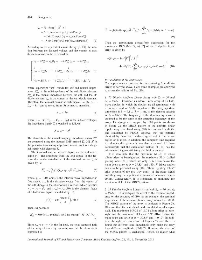
Vm ¼ hz � h expð�jk*i � r*Þ
¼ hz � ðx cos h cos/þ y cos h sin/
� z sin hÞ exp½jkðr1 þ dm sin h cos/Þ�¼ �h sin h expðjkr1Þ expðjkdm sin h cos/Þ ð2Þ
According to the equivalent circuit theory [2, 13], the rela-
tion between the induced voltage and the current at each
dipole terminal can be expressed as
V1 ¼ ðZsm11 þ ZLÞI1 þ � � � þ Zsm
1mIm þ � � � þ Zsm1NIN
..
. ... ..
. ... ..
.
Vm ¼ Zsmm1I1 þ � � � þ ðZsm
mm þ ZLÞIm þ � � � þ ZsmmNIN
..
. ... ..
. ... ..
.
VN ¼ ZsmN1I1 þ � � � þ Zsm
NmIm þ � � � þ ðZsmNN þ ZLÞIN
8>>>>>>><>>>>>>>:
(3)
where superscript ‘‘sm’’ stands for self and mutual imped-
ance; Zsmmm is the self-impedance of the mth dipole element;
Zsmmn is the mutual impedance between the mth and the nthdipole element; Im is the current at the mth dipole terminal.
Therefore, the terminal current at each dipole I ¼ {I1, I2, ���,Im, ��� IN} can be solved from (3) by matrix inversion.
I ¼ Z�1V (4)
where V ¼ {V1, V2, ���, Vm, ��� VN} is the induced voltages;
the impedance matrix Z is obtained as follows:
Z ¼ Zsm þ ZL (5)
The elements of the mutual coupling impedance matrix Zsm
are computed using the induced EMF method [2, 20]. ZL is
the generator terminating impedance matrix, so it is a diago-
nal matrix with elements ZL.The terminal current at each dipole can be calculated
using (4). The scattering from the mth dipole in the far-
zone due to the re-radiation of the terminal current Im is
given by [2]
E*s
m ¼ jg02p
f ðhÞIm expð�jk* � r*mÞ=rm (6)
where g0 ¼ 120p ohms is the intrinsic wave impedance in
free space; r*m is the distance vector from the center of
the mth dipole in the observation direction, which satisfies
r*m ¼ r
*1 � d
*
m and j r*mj ¼ rm; f(y) is the element factor
of a half-wave dipole calculated by [16]
f ðhÞ ¼ cosp cos h
2
� �= sin h (7)
Then (6) becomes
E*s
m ¼ j60f ðhÞIm expðjkdm sin h cos/Þ expð�jk* � r*1Þ=rm
(8)
Since rm � r1 ¼ r in the far-field, the total scattered field
of the array obtained by summing over all the elements is
expressed as
E*s ¼ j60f ðhÞ expð�jk
* � r*1Þ=r �XNm¼1
Im expðjkdm sin h cos/Þ
(9)
Then the approximate closed-form expression for the
monostatic RCS (MRCS, r) [2] of an N dipoles linear
array is given by
rðh;uÞ ¼ 4pr2 E*s��� ���2= E
*i��� ���2
¼ 4p 60f ðhÞ �XNm¼1
Im expðjkdm sin h cos/Þ�����
�����2
(10)
B. Validation of the ExpressionThe approximate expression for the scattering from dipole
arrays is derived above. Here some examples are analyzed
to assess the validity of Eq. (10).
1. 15 Dipoles Uniform Linear Array with ZL ¼ 50 andd0 ¼ 0.65k. Consider a uniform linear array of 15 half-
wave dipoles, in which the dipoles are all terminated with
a uniform load of 50-X impedance. The array aperture
dimension is L ¼ 9.1 k (k ¼ 1 m), so the element spacing
is d0 ¼ 0.65k. The frequency of the illuminating wave is
assumed to be the same as the operating frequency of the
array. The f-region is sampled by 1001 points. As shown
in Figure 2a, the MRCS pattern of the uniform linear
dipole array calculated using (10) is compared with the
one simulated by FEKO. Observe that the patterns
obtained by these two methods agree well in the whole
region of f-angle. In addition, the computer time required
to calculate this pattern is less than a second. All these
demonstrate that the calculation method of (10) has the
advantages of great efficiency and high accuracy.
It is also note that the maximum MRCS of 21.24
dBsm arises at boresight and the maximum SLLs (called
grating lobes [21]), which are only 6.06 dBsm below the
main beam arise at f ¼ 39.83� and 140.17� [these angles
can also be predicted using (10)]. These ‘‘grating lobes’’
arise because of the two way transit of the radar signal
and they may be significant in terms of increased detect-
ability. Consequently, it is significant to minimize the
maximum SLL of the MRCS pattern.
2. 15 Dipoles Uniform Linear Array with ZL ¼ 70 and d0¼ 0.65k. To investigate the effect of the terminal imped-
ance on the accuracy of (10), as an example, the terminal
impedance of the aforementioned array is reset as 70 X.The MRCS pattern of the array is depicted in Figure 2b.
Observe that the calculated and simulated results agree
well. The maximum MRCS of 19.72 dBsm arises at bore-
sight and the maximum SLLs are 5.96 dBsm below the
main beam and arise at f ¼ 39.83� and 140.17�. In addi-
tion, through the comparison of Figures 2a and 2b, it is
found that different load impedances only make the array
have different amplitude of MRCS. However, the shape of
the MRCS pattern is unchanged. Hence, no matter what
624 Zhang et al.
International Journal of RF and Microwave Computer-Aided Engineering/Vol. 21, No. 6, November 2011

impedance is connected to the element, the proposed
method remains working. In the following examples, the
dipoles are all terminated with 50-X impedance.
3. 15 Dipoles Uniform Linear Array with ZL ¼ 50 andd0 ¼ 0.1k. In this section, the effect of the element spac-
ing between two adjacent elements on the accuracy of
(10) is investigated. For the same array of 15 dipoles, the
element spacing is chosen to be as small as 0.1 k to
achieve strong mutual coupling effects. To illustrate the
advantage of consideration of the mutual coupling effects
and the stability of the proposed method, the MRCS pat-
tern calculated using the proposed method is compared
with that computed using the pattern multiplication
method (without mutual coupling) in Refs. 3 and 4 and
using FEKO in Figure 3.
Note that the results computed using the pattern multi-
plication method (dotted line) are consistent with those
simulated by FEKO (solid line) in the range of main
beam. Away from the main lobe, the pattern multiplica-
tion method fails since the mutual coupling cause signifi-
cant variation in the element patterns across the array.
Fortunately, as expected, the pattern calculated using the
proposed method (dashed line) agrees well with the one
simulated by FEKO. The comparisons above demonstrate
that the proposed method does lead to a more accurate
representation of the scattered field than the pattern multi-
plication method. A comparison between Figures 2a and 3
indicates that the scattering patterns calculated with the
proposed method for various interelement spacing have a
similar accuracy, which verifies the reliability and general-
ity of the proposed expression of (10).
4. 40 Dipoles Uniform Linear Array with ZL ¼ 50 andd0 ¼ 0.4k. In this section, the effect of the number of
array elements on the accuracy of (10) is investigated.
Consider a uniform linear array of 40 half-wave dipoles,
in which the elements are spaced by distance of d0 ¼ 0.4k(k ¼ 0.1 m). The MRCS pattern of the array is shown in
Figure 4. The maximum MRCS of 27.45 dBsm arises at
boresight and the maximum SLL is 13.38 dBsm below
the main beam. Differently from the MRCS pattern in
Figure 2, there are no grating lobes in the MRCS pattern
because of the element spacing is less than 0.5 k.
Figure 2 MRCS pattern of the uniform array of 15-dipole in
the y ¼ p/2 plane, as calculated by (10) (dotted line) and simu-
lated by FEKO (solid line): (a). ZL ¼ 50, (b). ZL ¼ 70.
Figure 3 MRCS pattern of a uniform linear array of 15-dipole,
in which the elements are spaced by distance of 0.1k.
Figure 4 MRCS pattern of the uniform array of 40-dipole in
the y ¼ p/2 plane, as calculated by (10) (dotted line) and simu-
lated by FEKO (solid line).
RCS Pattern Optimization of Dipole Arrays 625
International Journal of RF and Microwave Computer-Aided Engineering DOI 10.1002/mmce
Meanwhile, as expected, the calculated pattern is in good
agreement with the one simulated by FEKO.
The above examples demonstrate that (10) can rigor-
ously consider the mutual coupling between dipoles, so that
it can become the basis of an iterative technique to accu-
rately synthesize prescribed RCS pattern of dipole arrays.
C. Synthesis MethodAs expressed in (10), the MRCS pattern of dipole array is
a function of the element positions. Thus, similar to the
synthesis method for desired radiation pattern, a method is
proposed for synthesis of desired scattering pattern of
dipole arrays by adjusting the element positions using GA
[17]. In the proposed synthesis method, eq. (10) is used to
evaluate the fitness function of GA. Since (10) can take
the mutual coupling effects into account, the proposed
synthesis method is a more accurate iterative technique
compared with the one described in our previous work
[4]. Here, we only consider the MRCS pattern in the y ¼p/2 plane, so the fitness function of GA is defined as
fitnessðd1; � � � ; dNÞ ¼ minfmax½10 � lgð rðp=2;/Þj j=rmaxj jÞ�g ð11Þ
where the optimal variable d ¼ {d1, d2, ���, dN} acts as an
individual (which means the element positions vector of
the array), and the coding scheme of GA is real-coded; in
the optimization, the array aperture dimension remains a
constant; since the first element is located at the origin of
coordinate system (d1 ¼ 0), the coordinate of the Nth ele-
ment is always L (dN ¼ L, L is the array aperture dimen-
sion); 0 � f � p and the valid region of f excludes the
main beam of it; |rmax| is the peak value of the main
beam; thus max[10� lg(| r(p/2,f)|/|rmax)] is the maximum
SLL of the normalized MRCS pattern.
III. NUMERICAL EXAMPLE
To assess the validity of the proposed synthesis method, a
FORTRAN program is written for a PC (3.4-GHz Core 2
Duo processor, 2GBytes). In the program, basic parame-
ters of GA are set as follows: population includes 50 indi-
viduals; number of generation is 50; the crossover and
mutational probabilities are 85 and 0.5%, respectively; the
f-region is sampled by 1001 points; the tournament selec-
tion and elitism are used in the process of creating the
new generation.
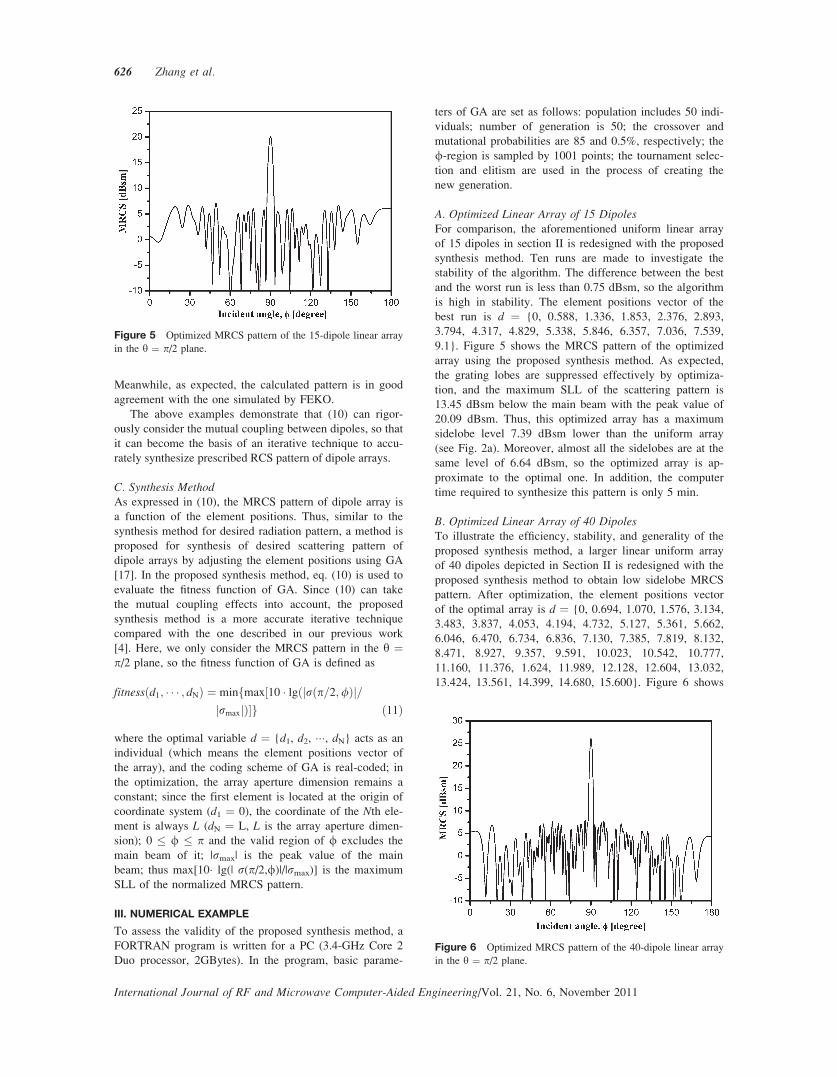
A. Optimized Linear Array of 15 DipolesFor comparison, the aforementioned uniform linear array
of 15 dipoles in section II is redesigned with the proposed
synthesis method. Ten runs are made to investigate the
stability of the algorithm. The difference between the best
and the worst run is less than 0.75 dBsm, so the algorithm
is high in stability. The element positions vector of the
best run is d ¼ {0, 0.588, 1.336, 1.853, 2.376, 2.893,
3.794, 4.317, 4.829, 5.338, 5.846, 6.357, 7.036, 7.539,
9.1}. Figure 5 shows the MRCS pattern of the optimized
array using the proposed synthesis method. As expected,
the grating lobes are suppressed effectively by optimiza-
tion, and the maximum SLL of the scattering pattern is
13.45 dBsm below the main beam with the peak value of
20.09 dBsm. Thus, this optimized array has a maximum
sidelobe level 7.39 dBsm lower than the uniform array
(see Fig. 2a). Moreover, almost all the sidelobes are at the
same level of 6.64 dBsm, so the optimized array is ap-
proximate to the optimal one. In addition, the computer
time required to synthesize this pattern is only 5 min.
B. Optimized Linear Array of 40 DipolesTo illustrate the efficiency, stability, and generality of the
proposed synthesis method, a larger linear uniform array
of 40 dipoles depicted in Section II is redesigned with the
proposed synthesis method to obtain low sidelobe MRCS
pattern. After optimization, the element positions vector
of the optimal array is d ¼ {0, 0.694, 1.070, 1.576, 3.134,
3.483, 3.837, 4.053, 4.194, 4.732, 5.127, 5.361, 5.662,
6.046, 6.470, 6.734, 6.836, 7.130, 7.385, 7.819, 8.132,
8.471, 8.927, 9.357, 9.591, 10.023, 10.542, 10.777,
11.160, 11.376, 1.624, 11.989, 12.128, 12.604, 13.032,
13.424, 13.561, 14.399, 14.680, 15.600}. Figure 6 shows
Figure 5 Optimized MRCS pattern of the 15-dipole linear array
in the y ¼ p/2 plane.
Figure 6 Optimized MRCS pattern of the 40-dipole linear array
in the y ¼ p/2 plane.
626 Zhang et al.
International Journal of RF and Microwave Computer-Aided Engineering/Vol. 21, No. 6, November 2011
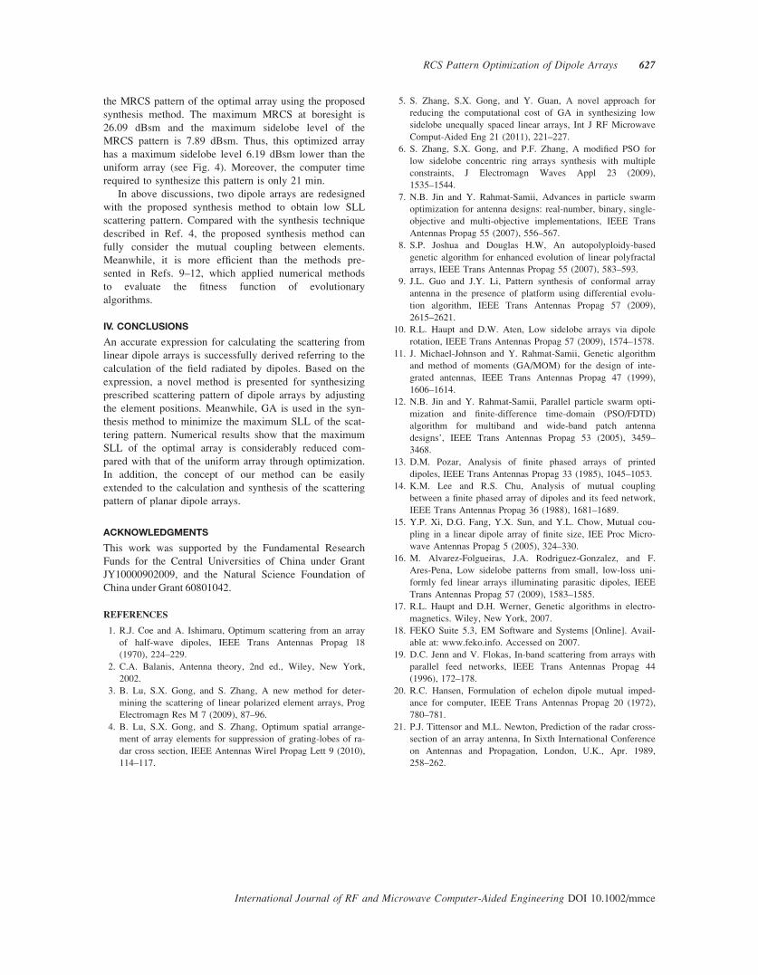
the MRCS pattern of the optimal array using the proposed
synthesis method. The maximum MRCS at boresight is
26.09 dBsm and the maximum sidelobe level of the
MRCS pattern is 7.89 dBsm. Thus, this optimized array
has a maximum sidelobe level 6.19 dBsm lower than the
uniform array (see Fig. 4). Moreover, the computer time
required to synthesize this pattern is only 21 min.
In above discussions, two dipole arrays are redesigned
with the proposed synthesis method to obtain low SLL
scattering pattern. Compared with the synthesis technique
described in Ref. 4, the proposed synthesis method can
fully consider the mutual coupling between elements.
Meanwhile, it is more efficient than the methods pre-
sented in Refs. 9–12, which applied numerical methods
to evaluate the fitness function of evolutionary
algorithms.
IV. CONCLUSIONS
An accurate expression for calculating the scattering from
linear dipole arrays is successfully derived referring to the
calculation of the field radiated by dipoles. Based on the
expression, a novel method is presented for synthesizing
prescribed scattering pattern of dipole arrays by adjusting
the element positions. Meanwhile, GA is used in the syn-
thesis method to minimize the maximum SLL of the scat-
tering pattern. Numerical results show that the maximum
SLL of the optimal array is considerably reduced com-
pared with that of the uniform array through optimization.
In addition, the concept of our method can be easily
extended to the calculation and synthesis of the scattering
pattern of planar dipole arrays.
ACKNOWLEDGMENTS
This work was supported by the Fundamental Research
Funds for the Central Universities of China under Grant
JY10000902009, and the Natural Science Foundation of
China under Grant 60801042.
REFERENCES
1. R.J. Coe and A. Ishimaru, Optimum scattering from an array
of half-wave dipoles, IEEE Trans Antennas Propag 18
(1970), 224–229.
2. C.A. Balanis, Antenna theory, 2nd ed., Wiley, New York,
2002.
3. B. Lu, S.X. Gong, and S. Zhang, A new method for deter-
mining the scattering of linear polarized element arrays, Prog
Electromagn Res M 7 (2009), 87–96.
4. B. Lu, S.X. Gong, and S. Zhang, Optimum spatial arrange-
ment of array elements for suppression of grating-lobes of ra-
dar cross section, IEEE Antennas Wirel Propag Lett 9 (2010),
114–117.
5. S. Zhang, S.X. Gong, and Y. Guan, A novel approach for
reducing the computational cost of GA in synthesizing low
sidelobe unequally spaced linear arrays, Int J RF Microwave
Comput-Aided Eng 21 (2011), 221–227.
6. S. Zhang, S.X. Gong, and P.F. Zhang, A modified PSO for
low sidelobe concentric ring arrays synthesis with multiple
constraints, J Electromagn Waves Appl 23 (2009),
1535–1544.
7. N.B. Jin and Y. Rahmat-Samii, Advances in particle swarm
optimization for antenna designs: real-number, binary, single-
objective and multi-objective implementations, IEEE Trans
Antennas Propag 55 (2007), 556–567.
8. S.P. Joshua and Douglas H.W, An autopolyploidy-based
genetic algorithm for enhanced evolution of linear polyfractal
arrays, IEEE Trans Antennas Propag 55 (2007), 583–593.
9. J.L. Guo and J.Y. Li, Pattern synthesis of conformal array
antenna in the presence of platform using differential evolu-
tion algorithm, IEEE Trans Antennas Propag 57 (2009),
2615–2621.
10. R.L. Haupt and D.W. Aten, Low sidelobe arrays via dipole
rotation, IEEE Trans Antennas Propag 57 (2009), 1574–1578.
11. J. Michael-Johnson and Y. Rahmat-Samii, Genetic algorithm
and method of moments (GA/MOM) for the design of inte-
grated antennas, IEEE Trans Antennas Propag 47 (1999),
1606–1614.
12. N.B. Jin and Y. Rahmat-Samii, Parallel particle swarm opti-
mization and finite-difference time-domain (PSO/FDTD)
algorithm for multiband and wide-band patch antenna
designs’, IEEE Trans Antennas Propag 53 (2005), 3459–
3468.
13. D.M. Pozar, Analysis of finite phased arrays of printed
dipoles, IEEE Trans Antennas Propag 33 (1985), 1045–1053.
14. K.M. Lee and R.S. Chu, Analysis of mutual coupling
between a finite phased array of dipoles and its feed network,
IEEE Trans Antennas Propag 36 (1988), 1681–1689.
15. Y.P. Xi, D.G. Fang, Y.X. Sun, and Y.L. Chow, Mutual cou-
pling in a linear dipole array of finite size, IEE Proc Micro-
wave Antennas Propag 5 (2005), 324–330.
16. M. Alvarez-Folgueiras, J.A. Rodriguez-Gonzalez, and F.
Ares-Pena, Low sidelobe patterns from small, low-loss uni-
formly fed linear arrays illuminating parasitic dipoles, IEEE
Trans Antennas Propag 57 (2009), 1583–1585.
17. R.L. Haupt and D.H. Werner, Genetic algorithms in electro-
magnetics. Wiley, New York, 2007.
18. FEKO Suite 5.3, EM Software and Systems [Online]. Avail-
able at: www.feko.info. Accessed on 2007.
19. D.C. Jenn and V. Flokas, In-band scattering from arrays with
parallel feed networks, IEEE Trans Antennas Propag 44
(1996), 172–178.
20. R.C. Hansen, Formulation of echelon dipole mutual imped-
ance for computer, IEEE Trans Antennas Propag 20 (1972),
780–781.
21. P.J. Tittensor and M.L. Newton, Prediction of the radar cross-
section of an array antenna, In Sixth International Conference
on Antennas and Propagation, London, U.K., Apr. 1989,
258–262.
RCS Pattern Optimization of Dipole Arrays 627
International Journal of RF and Microwave Computer-Aided Engineering DOI 10.1002/mmce

BIOGRAPHIES
Shuai Zhang was born in Hubei
province, China. He received the
B.S. degree in Electromagnetic Field
and Microwave Technique from
Xidian University, Xi’an, in 2007.
He is currently working toward the
Ph.D. degree at Xidian University in
Electromagnetic Field and Micro-
wave Technique. His current research interests include
antennas, arrays, calculation, and synthesis of the radiation
and scattering patterns of array antennas, and optimization
methods in electromagnetics.
Shu Xi Gong was born in Hebei
province, China, in 1957. He was
currently the Professor and Tutor of
Doctor in Xidian University. His
research interests include electromag-
netic theory, computational electro-
magnetics, antennas, antenna arrays,
and radiate wave propagation and
scattering in various media.
Ying Guan was born in Shaanxi
province, China. He received the
B.S. degree in Electromagnetic Field
and Microwave Technique from
Xidian University, Xi’an, in 2007.
He is currently working toward the
Ph.D. degree at Xidian University in
electromagnetic field and microwave
technique. His research interests focus on the numerical
methods in solving electromagnetic problems.
Bao Lu was born in Shaanxi province,
China. He received the B.S. degree in
Electromagnetic Field and Microwave
Technique from Xidian University,
Xi’an, in 2004. He is currently working
toward the Ph.D. degree at Xidian
University in Electromagnetic Field and
Microwave Technique. His research
interests focus on electromagnetic scattering, frequency selec-
tive surfaces, electromagnetic bandgap structures, and RCS
prediction and measurement programs.
International Journal of RF and Microwave Computer-Aided Engineering/Vol. 21, No. 6, November 2011
628 Zhang et al.