Embed Size (px)
Citation preview

TUNNEL & UNDERGROUND SPACE Vol.29, No.6, 2019, pp.480-507
https://doi.org/10.7474/TUS.2019.29.6.480 ISSN: 1225-1275(Print) ISSN: 2287-1748(Online)
ORIGINAL ARTICLE
대단면 지하 석회석 광산내 무풍관 국부통기 최적화 연구
응우엔반득1, 이창우2*
1동아대학교 공과대학 에너지・자원공학과 박사과정, 2동아대학교 공과대학 에너지・자원공학과 교수
Optimization of the Unducted Auxiliary Ventilation for Large-Opening
Underground Limestone Mines
Van Duc Nguyen1 and Chang Woo Lee2*
1PhD Student, Dong-A University, Energy and Mineral Resources Department2Professor, Dong-A University, Energy and Mineral Resources Department
*Corresponding author: [email protected]
ABSTRACT
Received: December 3, 2019
Revised: December 19, 2019
Accepted: December 19, 2019
This paper aims at optimizing the auxiliary ventilation system in large-opening limestone
mines with unducted fans. An extensive CFD and also site study were carried out for
optimization at the blind entries. The fan location, operating mode, and layout are the
parameters for optimization. Since the jet stream discharged from the auxiliary fan is flowing
faster than 15 m/s in most of the cases, the stream collides with floor, sides or roof and even
with the jet stream generated from the other fan placed upstream. Then, it is likely to lose a
large portion of its inertial force and then its ventilation efficiency drops considerably.
Therefore, the optimal fan installation interval is defined in this study as an interval that
maximizes the uninterrupted flowing distance of the jet stream, while the cross-sectional
installation location can be optimized to minimize the energy loss due to possible collision
with the entry sides. Consequently, the optimization of the fan location will improve ventilation
efficiency and subsequently the energy cost. A number of different three-dimensional
computational domains representing a full-scale underground space were developed for the
CFD study. The velocity profiles and the CO concentrations were studied to design and
optimize the auxiliary ventilation system without duct and at the same time mine site
experiments were carried out for comparison purposes. The ultimate goal is to optimize the
auxiliary ventilation system without tubing to provide a reliable, low-cost and efficient
solution to maintain the clean and safe work environment in local large-opening underground
limestone mines.
Keywords: Auxiliary unducted-fan system, CFD analysis, Large-opening mine, Ventilation
efficiency, Ventilation tubing
초록
본 논문은 무풍관 선풍기를 이용한 대단면 갱내 국부통기시스템의 최적화를 목적으로 한다. 갱내 맹갱도
형태의 작업공간을 대상으로 일련의 CFD분석과 현장실험을 수행하였다. 선풍기 위치, 운전방식 및 배치
가 최적화의 주요 대상변수이다. 국부선풍기에서 토출되는 제트류는 대부분의 경우, 풍속이 15m/s이상
으로 고속이므로 토출 후 갱도 바닥, 내벽, 천정 그리고 다른 선풍기에서 토출되는 제트류와 충돌할 가능
성이 있다. 따라서 충돌시 상당한 에너지 손실이 발생하므로 통기 효율이 급격히 저하될 수 있다. 본 논문
Ⓒ The Korean Society for Rock Mechanics and Rock Engineering 2019. This is an Open Access article distributed under the terms of the Creative Commons Attrib-ution Non-Commercial License (http://creativecommons.org/ licenses/by-nc/4.0/) which permits unrestricted non-commercial use, distribution, and reproduction in any medium, provided the original work is properly cited.

Optimization of the Unducted Auxiliary Ventilation for Large-Opening Underground Limestone Mines ∙ 481
TUNNEL & UNDERGROUND SPACE Vol. 29, No. 6, 2019
1. INTRODUCTION
Due to the large cross-sectional and long blind entries common in local limestone mines, most of the working sites are
entirely dependent upon the auxiliary ventilation system. For this purpose, high-capacity axial-flow fans are generally
employed with tubings to supply fresh air to the working area. However, several problems with this type of fan-with-tubing
auxiliary ventilation system are observed to be significant and become the main causes of the low ventilation efficiency. To
name a few, the inefficiency of high-capacity fans, poor management of fan and tubings and improper location of the system
are those. The results indicate that at some specific underground conditions, the current auxiliary ventilation system is found
to be insufficient to supply the fresh air up to the working sites and to dilute the contaminated air in the working environment.
These issues must be carefully considered by the mine ventilation system designers. As a result, it is challenging to optimize
the auxiliary ventilation system for large-opening airways since the mine ventilation system is not properly implemented in
harmony with the production plan.
In this study, a series of the auxiliary ventilation schemes with different types of auxiliary fans such as conventional
axial-flow fans and large-diameter propeller fan without tubing are discussed by the empirical and CFD analysis. The study
aims at optimizing fan locations with respect to longitudinal fan intervals and cross-sectional position. The propeller fan is an
axial-flow and relatively large-diameter fan and is operated at a lower speed, while it can generate lower static pressure but a
higher flow rate compared to the fans currently installed in underground mines. The number of fans, fan location, and fan
operating mode are scrutinized to assess the effectiveness and also to find the optimal unducted fan operating variables. The
ultimate goal of this study is to derive the low cost and efficient auxiliary ventilation system in the large-opening local mines
with relatively long blind working entries.
2. AUXILIARY VENTILATION SYSTEM FOR LARGE-OPENING WORKING SITE
As the local limestone mines go deeper and the working place environment subsequently deteriorates, auxiliary ventilation
systems have received considerable attention for several reasons. Firstly, since most of the mines are completely dependent
on natural ventilation, some of the blind workings immediately need any form of mechanical ventilation method to reduce the
contamination level for sustainable development. Secondly, most of the openings are driven without separate intake and
에서 최적 선풍기 간격은 제트류가 충돌 없이 최대의 유동거리를 유지할 수 있는 거리로 정의하며, 반면
단면상의 최적 위치란 갱도내벽과의 충돌 가능성이 최소화된 위치로 정의하였다. 따라서 선풍기 설치위
치의 최적화는 통기의 효율뿐만 아니라 에너지 비용 또한 최소화가 가능하다. 3차원 CFD분석을 위하여
다양한 갱내 맹갱도 작업공간을 가정하였다. 무풍관 국부통기의 설계 및 최적화를 위하여 풍속 및 CO농
도 분포를 CFD분석하였으며 동시에 비교 목적으로 현장실험을 수행하였다. 본 논문의 궁극적인 목적은
풍관을 사용하기 않는 국부통기시스템을 최적화함으로써 대단면 맹갱도 작업공간에 고효율, 저비용 국
부통기를 가능케하여 깨끗하고 안전한 작업환경을 확보하기 위함이다.
핵심어: 무풍관 국부통기시스템, CFD분석, 대단면 갱도 광산, 환기효율, 통기효율, 퉁기풍관

482 ∙ Van Duc Nguyen and Chang Woo Lee
TUNNEL & UNDERGROUND SPACE Vol. 29, No. 6, 2019
return airways, and thus the auxiliary ventilation scheme is inevitable. Thirdly, it is impractical to use large-capacity main
fans and develop ventilation shafts to complete the ventilation network construction due to excessively high capital
requirements. Thus, there is no doubt that ventilation problems experienced in local mine workings must be solved
adequately by deploying auxiliary fans and tubings in a proper manner. The well-planned auxiliary ventilation system with
fan and tubings can supply a sufficient amount of fresh air directly to the workings and maintain the air quality under the
allowable limits.
Auxiliary ventilation systems that are used to supply fresh air to the working faces and dead-end headings can be classified
into three basic types, namely: “stopping line,” “fan and duct” and “ductless” systems. As described by Wallace (2001), with
an “auxiliary” ventilation system which can include a large number of auxiliary ducting systems (steel/fiber/fabric) and
auxiliary fans, fresh air is delivered to the working areas and should have no impact on the distribution of airflow in the total
mine ventilation network.
Various critical factors affect the air quantity to be moved to the face; those include the inclination of entry, the amount of
equipment moving in the face area, and most importantly, the auxiliary fan type, fan nozzle, location and orientation (Dunn et
al, 1983). Gaul et al (2006) mentioned that the stopping designs and techniques suitable for use in coal mines generally could
not be applied in limestone mines due to the entry sizes and the associated cost of construction.
Auxiliary fan and tubing system can be used in blowing or exhaust modes with various combinations. As the dead-end
opening is driven longer, then one blowing fan may not be enough to keep the air quality within the desirable range, and in
most of the cases additional exhaust fan is deployed to carry out the contaminants in the air. An exhaust fan-and-tubing
auxiliary system would need to employ more expensive rigid ducts (such as steel ducts) or spiral type flexible ducts (Hartman
et al, 2002). In this case, the free-standing auxiliary fan without tubing is an alternative method. Graul and Krog (2009)
indicate that the correct auxiliary fan location should be outby the last open crosscut where it can entrain and blow fresh air
into the face area. Grau et al (2002) showed that the criteria for proper fan selection, installation, and operation for both main
mine fans and auxiliary fans should be carefully considered. Fan characteristics of pressure and quantity should be matched
for the operation. Ventilation studies have measured the performance of jet fans (usually axial vane free-standing) either in
single headings or ventilating portions of the main airways (Krog and Grau, 2006). These researches found that the most
important aspect of auxiliary fan performance is that the jet fan should be positioned in the intake incoming main air stream so
that there is sufficient intake air for the fan. Other important results from these tests showed that the performance of these fans
was enhanced by adding a nozzle to the fan. Results were also significantly improved by angling the fan upward and located
against a rib when ventilating a dead-ended opening.
Thus, the previous studies show that the unducted system can be an economical alternative to the common ducted fan
system and the proper placement of auxiliary fans plays a vital role in increasing the ventilation efficiency. In this paper,
various scenarios of the unducted-fan auxiliary ventilation system with one or two fans are evaluated with respect to the
ventilation efficiency by CFD analysis, while site experiments are carried out in dead-end openings for comparison purposes.

Optimization of the Unducted Auxiliary Ventilation for Large-Opening Underground Limestone Mines ∙ 483
TUNNEL & UNDERGROUND SPACE Vol. 29, No. 6, 2019
3. CFD ANALYSIS OF THE UNDUCTED-FAN INSTALLATION
3.1 CFD analysis method
Application of the CFD technique in mine ventilation can help mining engineers to analysis complex airflow fields and
contaminant transport in order to design a more economical and safer ventilation system (Ali Haghighat, 2014). Many
researchers such as Gosman (1999), Parra et al. (2006), Migoya et al. (2009), Colella et al. (2011), and Montazeri (2011) have
studied on the three-dimensional geometries of the various flow and thermal conditions by comparing the experimental and
numerical results. They showed quite good agreement between the numerical predictions and experimental measurements.
ANSYS-FLUENT which was adopted for this study has commonly been used by many researchers to study various
fluid-flow and heat transfer problems in underground ventilation engineering (ANSYS, Inc., 2019). The study by Yuandong
and Zhonghua (2013) was in good agreement with the experimental works for the airflow and pollutant dispersion by
Rafailidis and Schatzmann (1995) in a detailed wind tunnel study. In addition, numerous papers and technical reports on the
simulation of underground mine environments can be found by Gao et al. (2002), Stephen. (2002), Hargreaves and Lowndes.
(2007), Toraño et al. (2009), Zheng. (2011), Torno et al. (2013), and Zhongwei and Ting. (2013).
As described above, improper fan location may lead to low ventilation efficiency at the dead-end workings. In this study, three
kinds of fan, which commonly used as free-standing auxiliary fan, were chosen for CFD analysis to evaluate the parameters for
optimizing fan installation such as longitudinal fan interval and the cross-sectional position. Fig. 1 shows the three fans studied in
this study: 15 kW propeller fan, 15 kW jet fan, and 37 kW high-pressure jet fan. Their specifications can be seen in Table 1.
(a) 15 kW Propeller fan (b) 15 kW Jet fan (c) 37 kW Jet fan
Fig. 1. Three auxiliary fans for CFD analysis
Table 1. Fan specifications for CFD analysis
Categories 15 kW Propeller fan 15 kW low-pressure fan 37 kW high-pressure fan
Flow quantity (m3/s) 25 18.6 47.1
Diameter (m) 1.6 1.0 1.4
Pressure (Pa) 147 235 555.1
Discharge velocity(m/s) 16 20 30.6
Noise level (dB(A)) 85 85 89-95
Power (kW) 15 15 37
Length (m) 0.75 2.5 3.0
Weight (kg) 528 792 998

484 ∙ Van Duc Nguyen and Chang Woo Lee
TUNNEL & UNDERGROUND SPACE Vol. 29, No. 6, 2019
Table 2. Conditions of CFD analysis
Parameters CFD model
Inlet and outlet boundary Pressure inlet
Wall boundary Friction wall
Ventilation resistance (k) 0.013 kg/m3
Mesh type Tetrahedron elements
Number of mesh elements 1.500.000
Solution model Turbulence model (k-)
Mesh size function Proximity and curvature
Simulation condition Transient-state conditions
Fig. 2 (a) shows 3D model geometry of airway and the three fans studied in this study: 15 kW propeller fan, 15 kW jet fan,
and 37 kW high-pressure jet fan. The meshing domain can be seen in Fig. 2 (b). The CFD analysis conditions are summarized
in Table 2. The turbulence model was employed in this CFD study.
(a) 3D model geometry for CFD analysis
(b) 3D Meshing domain for CFD analysis
Fig. 2. 3D model geometry and meshing for CFD analysis

Optimization of the Unducted Auxiliary Ventilation for Large-Opening Underground Limestone Mines ∙ 485
TUNNEL & UNDERGROUND SPACE Vol. 29, No. 6, 2019
3.2 Analysis of the auxiliary unducted-fan installation location
Fig. 3 shows the velocity distributions over the vertical cross-section at 20 m downstream of the fan. Fig. 3 (a) shows that
in the cases of fan installation height of 0.5 and 1.0 m in, considerable momentum loss is likely to occur due to the collision of
the air stream with the floor, and much less loss can be observed in the cases of 1.5 and 2.0 m shown in Fig. 3 (b). A similar
pattern can be shown with all three fans. Considering that the installation height of the auxiliary fan in large-opening mine is
less than 1.0 m in most of the cases at local limestone mines, the current practices adopted from the experiences at the small
or medium-opening coal and ore mines can be easily considered one of the major causes of the low ventilation efficiency.
This analysis indicates that the height of the auxiliary fan should be more than 1.5 ~ 2.0 m to reduce the energy loss due to the
collision of the jet stream to the airway sidewalls.
(a) H = 0.5 m and H = 1.0 m
(b) H = 1.5 m and H = 2.0 m
Fig. 3. Cross-sectional velocity distributions at 20m downstream of the fan by the installation height
As the airway is getting longer and longer, only one auxiliary fan may not be enough to meet the ventilation requirement in
large-opening limestone mines. Multiple fans installed in series are necessary to secure auxiliary ventilation efficiency in the

486 ∙ Van Duc Nguyen and Chang Woo Lee
TUNNEL & UNDERGROUND SPACE Vol. 29, No. 6, 2019
long blind entry. Fig. 4 shows the longitudinal velocity profiles of the airflow with the different fan intervals of 50, 70, and
100 m, respectively. It can be seen that there was not much difference among them in terms of the reach of jet stream faster
than 5.0 m/s. However, as the interval increases, the airflow velocity at the inlet side of the downstream fan decreases; in the
case of 100 m, the inlet-side velocity was in the range of 1.0 ~ 2.0 m/s. Thus, this implies that in the case of multiple fans
installed in series the suitable fan interval should not be far more than 100 m to ensure ventilation efficiency of the fans.
Fig. 4. Longitudinal velocity profiles with different fan intervals
In the ideal case, the fan should be placed at the center of the airway cross-section to minimize the collision of the jet
stream. However, installing a fan at the center is impossible in most of the cases where the entry is used as the haulage way.
Fig. 5 illustrates the cross-sectional profiles of the air velocity by varying the gap length between the fan and entry sidewall.
Similarly, in the case of the gap length of 0.5, and 1.0 m shown in Fig. 5 (a), and (b), the high energy loss of jet stream was
observed due to the collision with the sidewall, while it was reduced for the gap length of 1.5 and 2.0 m shown in Fig. 5 (c),
and (d). The results show that the gap length between fan and sidewall should be larger than 1.0m. Fig. 5 (e) shows the results
when the fan was horizontally rotated toward the center at approximately 17 degrees. It implies that changing the fan axial
angle toward the center horizontally or vertically can reduce the possibility of the jet stream collision and subsequently
improve ventilation efficiency.
Fig. 5. Cross-sectional velocity distributions by varying the gap between fan and side wall

Optimization of the Unducted Auxiliary Ventilation for Large-Opening Underground Limestone Mines ∙ 487
TUNNEL & UNDERGROUND SPACE Vol. 29, No. 6, 2019
3.3 Analysis of the auxiliary fan layout in a single blind airway
Lee and Nguyen (2015) indicated that in large-opening limestone mines, the high-pressure axial-flow fans used commonly
have excessive capacity and low efficiency. The low-pressure axial-flow fan was strongly recommended for local limestone
mine due to the potentials of higher ventilation efficiency, less capital and operating costs. In this study, a low-pressure 15kW
propeller fan was introduced for the analysis and its characteristics are listed in Table 1. The number of fans, fan location, and
fan operating mode were the study topics. For the study, three scenarios summarized in Table 3 were designed to investigate
the ventilation efficiency of the unducted fan system in a single-blind airway, 230 m (long) x 10 m (wide) x 8 m (high). The
CFD analysis conditions were same as in Table 2.
The optimal ventilation system is the one where the intake and return airflows are separated and also sufficient enough to
dilute the contaminants away from the working sites. In the analysis scenarios, the gas concentration profiles in the working
area were simulated to evaluate the ventilation efficiency. For the CFD simulation, two heavy trucks located at the dead-end
working face were assumed to emit CO continuously at the rate of 0.613 m3/h (Road design guidelines, 2010). The total
simulation time was 30 minutes. The CO concentration distribution was used as the criterion for evaluating the gas dispersion
efficiency of fan operation. The results are discussed in the following sections.
Table 3. Scenarios for the auxiliary unducted-fan layout in blind airway
CFD Scenarios Description Layouts for CFD analysis
Scenario I
- One blowing fan is employed.
- Fan location varies within 30
- 180m from the working face
Scenario II
- One blowing fan is installed at 80 m
from the working face, and one exhaust
fan on the opposite side of the airway
at 0
- 50 m downstream the blowing fan
- Specifications of two fans are
assumed to be identical.
Scenario III
- Two exhaust fans are placed in series.
- The distance between fan and the
working face is 30 m.
- The effects of the fan intervals be-
tween 50 to 100 m on the ventilation
efficiency are investigated.
3.3.1 Scenario I with one blowing fan
Fig. 6 shows the air velocity and CO concentration contours on the horizontal planes over the entire 230 m-long airway at
the height of 2.0, 4.0 and 6.0 m. The airflow velocity observed near the working face was nearly 2.0 m/s. However,
considerable recirculation of airflow was observed near the fan location with the velocity of 0.4-0.6 m/s at the height of 2.0

488 ∙ Van Duc Nguyen and Chang Woo Lee
TUNNEL & UNDERGROUND SPACE Vol. 29, No. 6, 2019
and 4.0 m. Since even with the fan operation, air exchange through the inlet plane was extremely limited, it indicates that
most of the air in the working domain continued to be recirculated.
(a) U velocity profile
(b) CO concentration after 30-minute fan operation
Fig. 6. Air velocity and CO concentration profiles by height in Scenario I
This observation is well described in Fig. 6 (b) displaying the CO concentrations after the 30-minute simulation in case of
the fan at 50 m downstream. CO concentrations on the most portion of the cross-section were above 50 ppm within 150 m
from the face as shown in Fig. 6 (b), mainly due to the recirculation. This indicates that the fast-moving airstream discharged
by the fan could reach the working face and subsequently the polluted air was discharged through the upper half of the airway.
However, most of the outby airflow was sucked into the fan and recirculated. This aggravated the air quality near the working
place as time went by.
Inby and outby airflow rate, average CO concentration on the cross-section and average CO flow rate in the in-and outflows
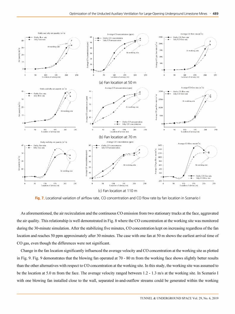
are plotted by distance in Fig. 7. The origin of the x-axis is the inlet portal; the working face is at 230 m. The fan locations are
50 m, 70 m, and 110 m downstream of the working face. The CO flow rate in m3/s is used as an indicator of the fan ventilation
efficiency. Comparisons of the CO flow rates in the in- and outflow clearly show that within the working space ahead of the
fan, the CO concentrations and flow rates in the outflow exceeded those in the inflow. This implies that as shown in Fig. 7 (a),
the air was recirculating between the fan, and the working face and CO generated by trucks at the face continued to be added to
the flow. However, Fig. 7 (b) shows how the mechanism of the turbulent diffusion is related to the diffusion of CO passing the
fan; even though the air velocity was nearly zero, the CO concentration was still high even in the upstream. However, there was
no inflow and outflow of the air and CO observed through the inlet portal. A similar pattern can be observed in Fig. 7 (c).
Optimization of the Unducted Auxiliary Ventilation for Large-Opening Underground Limestone Mines ∙ 489
TUNNEL & UNDERGROUND SPACE Vol. 29, No. 6, 2019
(a) Fan location at 50 m
(b) Fan location at 70 m
(c) Fan location at 110 m
Fig. 7. Locational variation of airflow rate, CO concentration and CO flow rate by fan location in Scenario I
As aforementioned, the air recirculation and the continuous CO emission from two stationary trucks at the face, aggravated
the air quality. This relationship is well demonstrated in Fig. 8 where the CO concentration at the working site was monitored
during the 30-minute simulation. After the stabilizing five minutes, CO concentration kept on increasing regardless of the fan
location and reaches 50 ppm approximately after 30 minutes. The case with one fan at 50 m shows the earliest arrival time of
CO gas, even though the differences were not significant.
Change in the fan location significantly influenced the average velocity and CO concentration at the working site as plotted
in Fig. 9. Fig. 9 demonstrates that the blowing fan operated at 70 - 80 m from the working face shows slightly better results
than the other alternatives with respect to CO concentration at the working site. In this study, the working site was assumed to
be the location at 5.0 m from the face. The average velocity ranged between 1.2 - 1.3 m/s at the working site. In Scenario I
with one blowing fan installed close to the wall, separated in-and-outflow streams could be generated within the working

490 ∙ Van Duc Nguyen and Chang Woo Lee
TUNNEL & UNDERGROUND SPACE Vol. 29, No. 6, 2019
space, even though most of the outflow was recirculated through the fan and subsequently the CO level gradually increased at
the working site. However, the CO level at the working site was kept below 50 ppm within a 30-minute fan operation. The air
exchange through the inlet portal was minimal.
(a) Average velocity (b) CO concentration
Fig. 9. Effect of fan location on the average velocity and the CO concentration at working site
3.3.2 Scenario II with one blowing fan and one exhausting fan
According to the “new standards for mine safety technology” in Korea revised in 2017, the maximum allowable CO
concentration in the workplace is 30 ppm (8-hr TWA) at the working site. Thus, Scenario I is not a proper ventilation system
for local limestone mines. In Scenario II, one more fan was added to Scenario I and operated in exhaust mode. In Scenario II,
one blowing fan was set up at 80 m from the working face, and one exhaust fan was installed on the opposite side of the
airway at the locations 0 to 50 m downstream the blowing fan as in Table 2. The characteristics of the two fans were assumed
to be identical.
Fig. 8. CO concentration at working site after 30-minute simulation
Optimization of the Unducted Auxiliary Ventilation for Large-Opening Underground Limestone Mines ∙ 491
TUNNEL & UNDERGROUND SPACE Vol. 29, No. 6, 2019
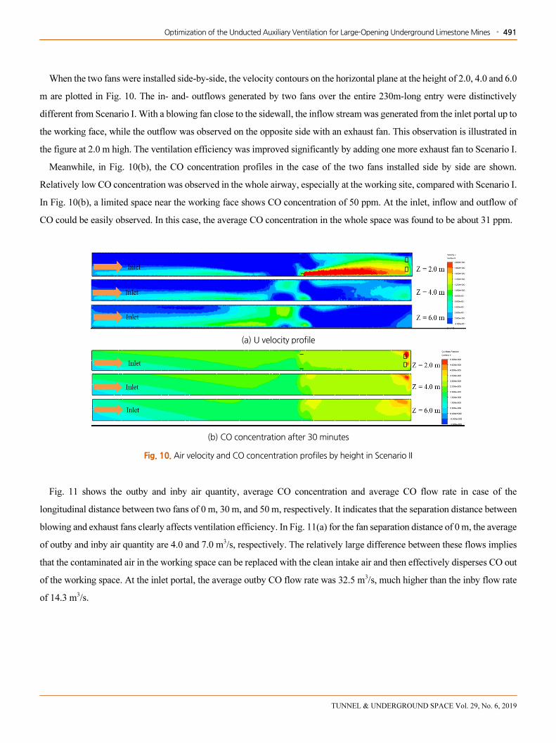
When the two fans were installed side-by-side, the velocity contours on the horizontal plane at the height of 2.0, 4.0 and 6.0
m are plotted in Fig. 10. The in- and- outflows generated by two fans over the entire 230m-long entry were distinctively
different from Scenario I. With a blowing fan close to the sidewall, the inflow stream was generated from the inlet portal up to
the working face, while the outflow was observed on the opposite side with an exhaust fan. This observation is illustrated in
the figure at 2.0 m high. The ventilation efficiency was improved significantly by adding one more exhaust fan to Scenario I.
Meanwhile, in Fig. 10(b), the CO concentration profiles in the case of the two fans installed side by side are shown.
Relatively low CO concentration was observed in the whole airway, especially at the working site, compared with Scenario I.
In Fig. 10(b), a limited space near the working face shows CO concentration of 50 ppm. At the inlet, inflow and outflow of
CO could be easily observed. In this case, the average CO concentration in the whole space was found to be about 31 ppm.
(a) U velocity profile
(b) CO concentration after 30 minutes
Fig. 10. Air velocity and CO concentration profiles by height in Scenario II
Fig. 11 shows the outby and inby air quantity, average CO concentration and average CO flow rate in case of the
longitudinal distance between two fans of 0 m, 30 m, and 50 m, respectively. It indicates that the separation distance between
blowing and exhaust fans clearly affects ventilation efficiency. In Fig. 11(a) for the fan separation distance of 0 m, the average
of outby and inby air quantity are 4.0 and 7.0 m3/s, respectively. The relatively large difference between these flows implies
that the contaminated air in the working space can be replaced with the clean intake air and then effectively disperses CO out
of the working space. At the inlet portal, the average outby CO flow rate was 32.5 m3/s, much higher than the inby flow rate
of 14.3 m3/s.

492 ∙ Van Duc Nguyen and Chang Woo Lee
TUNNEL & UNDERGROUND SPACE Vol. 29, No. 6, 2019
(a) fan separation distance of 0 m
(b) fan separation distance of 30 m
(c) fan separation distance of 50 m
Fig. 11. Locational variation of airflow rate, CO concentration and CO flow rate by fan separation distance in Scenario II
Fig. 11 (b), (c) shows the cases of the fan separation distance of 30 m and 50 m and similar results are observed. However,
as the fan separation distance increases, the difference between inby and outby flow rates decrease; the outby and inby flow
rates were 1.2 ~ 1.5 m3/s and 1.7 ~ 2.5 m3/s. Since the exhaust efficiency decreased with increasing separation distance, CO
centration near the working face was higher, showing the range of 37 ~ 43 ppm in Fig. 11 (b) and (c). Fig. 12 illustrates the
CO concentrations at the working site during a 30-minute simulation. As described in Fig. 11, CO concentration at the
working site was 29 ~ 30 ppm for the separation distance of 0 ~ 30 m and 44 ppm for 50 m; higher CO concentration was
observed with the larger separation distance between blowing and exhaust fans. Hence, the separation distance of 0 ~ 30 m
was found to show better results to dilute CO at the working site in the blind airway.

Optimization of the Unducted Auxiliary Ventilation for Large-Opening Underground Limestone Mines ∙ 493
TUNNEL & UNDERGROUND SPACE Vol. 29, No. 6, 2019
Fig. 12. CO concentration at working site during 30-minute simulation by one blowing and one exhaust fan
Fig. 13 shows that two fans separated by 0 ~ 30 m lead to relatively higher average air velocity and subsequently lower CO
concentration in the working area.
(a) Average velocity (a) CO concentration
Fig. 13. Average velocity and CO concentration distributions at the working site by one exhaust and one blowing fan
3.3.3 Scenario III with two exhaust fans in series
Scenario III was designed to evaluate the ventilation efficiency of the two exhaust fans installed in series. The distance
from the first fan to the working site was 30m and the interval between two fans ranged from 50 to 100 m. The details of
Scenario III can be seen in Table 2.
The longitudinal velocity profiles by height in the case of two exhaust fans 50 m apart are plotted in Fig. 14. The results
were significantly different from Scenario I and II. The high velocity of the outby flow was observed at the height of 2.0 - 4.0
m due to the exhaust operation. On the contrary, the velocity of inby flow was relatively low over the entire airway.

494 ∙ Van Duc Nguyen and Chang Woo Lee
TUNNEL & UNDERGROUND SPACE Vol. 29, No. 6, 2019
(a) U velocity profile
(b) CO concentration after 30-minute simulation
Fig. 14. Longitudinal velocity profiles by height with two exhaust fans 50 m apart
This low inby-flow velocity influenced the dilution of contaminated air. As shown in Fig. 14 (b), CO was in the range of 15 ~
20 ppm in the section from the inlet portal to 150 m, but the extremely high level of CO was observed near the working face
during the 30-minute simulation. The CO concentration reached 120 ppm near the face after 30 minutes of fan operation. The
airflow rate, CO concentration and CO flow rate in the outby and inby airflows are plotted in Fig. 15. As forementioned, the
average outby and inby flow velocities were extremely low at the working site. Fig. 15 (a) shows the case of two fans
separated by 50 m; the average inby and outby airflow rates were 7.62 m3/s and 4.68 m3/s, respectively. However, near the
working face, those flow rates were reduced to 2.33 m3/s and 1.75 m3/s. This led to the insufficient replacement of the
contaminated air near the working site. CO concentration was maintained in the range of 10 ~ 13 ppm in the section from the
inlet portal to 200 m locations, while it increased rapidly up to 124 ppm at the working site. In the case where two fans were
separated by 100 m, the concentration was even higher; it reached 212 ppm at the working site as in Fig. 15 (b).
(a) fan separation distance of 50 m
Fig. 15. Locational variation of airflow rate, CO concentration and CO flow rate by fan separation distance in Scenario III

Optimization of the Unducted Auxiliary Ventilation for Large-Opening Underground Limestone Mines ∙ 495
TUNNEL & UNDERGROUND SPACE Vol. 29, No. 6, 2019
(b) fan separation distance of 100 m
Fig. 15. Locational variation of airflow rate, CO concentration and CO flow rate by fan separation distance in Scenario III (Continued)
The results observed during the 30-minute simulation are plotted in Fig. 15. Due to the effect of exhaust mode operation,
the low average velocity of 0.03 ~ 0.04 m/s was measured at the working site. As shown in Fig. 16(b), insufficient replacement
of the air near the face resulted in low dilution efficiency and thus the high level of CO. After the 30-minute simulation with
two exhaust fans in series separated by 50 m and 100 m, high CO concentrations of 95 ppm and 152 ppm were measured at the
face. Thus, the CFD analysis of two exhaust fans in series shows that the ventilation efficiency was the worst among the three
scenarios due to the extremely low exhaust efficiency of two fans installed in series near the working site despite the higher
rate of air exchange through the inlet portal.
(a) Average velocity at working site (m/s) (b) CO concentration at working site (ppm)
Fig. 16. Average velocity and CO concentration distributions at the working site by two exhaust fans in series
3.4 Comparisons
The CFD analysis in this study indicated that the ventilation efficiency in the blind working site could be improved by the
appropriate installation of auxiliary fans. Scenario III with two exhaust fans in series was one of the worst auxiliary
ventilation systems in terms of the air replacement and contaminant dilution efficiency. This study shows that the ventilation
efficiency can be evaluated by the inby-and-outby flow rates and CO concentration within the working space. These two
evaluation criteria are closely related to the air replacement and contaminant dilution efficiency of the system. In Fig. 17, the
analysis results of all the cases studied in this study are summarized for comparison. Fig. 17 (a) shows that the average

496 ∙ Van Duc Nguyen and Chang Woo Lee
TUNNEL & UNDERGROUND SPACE Vol. 29, No. 6, 2019
velocity at the working site was extremely low for the system only with fans in the exhaust mode. While its average velocity
was in the range of 0.03 ~ 0.09 m/s, the case with the blowing fans showed a higher average velocity of 0.32 ~ 0.73 m/s. Due
to the low airflow replacement by the exhaust system, the highest CO concentration of 738 ppm was detected in the case of
one exhaust fan system. Among the 7 cases summarized in Fig. 17, the case with one blowing and one exhaust fan maintained
the lowest CO concentration level near the working area.
(a) average velocity (b) CO concentration
Fig. 17. Average velocity and CO concentration distributions at the working site of all cases
Table 4 summarizes the analysis results plotted in Fig. 17; it includes the in-and-out flow rates and the volume of CO above 30
ppm in all cases of the unducted fan system. Even though operating fans in exhaust mode generated higher in-and-outby flow
rates than fans in blowing mode, the inby airflow induced by the exhaust fans could hardly reach the working place. This
resulted in high CO level within the working space only by the exhaust auxiliary fans. However, when an additional blowing fan
was added to the exhaust fan system in Scenario II, it was found that more inby fresh air could reach the working face and
subsequently the CO level was lowered. Shown in Table 4, the system with one blowing and one exhaust fan induced the inby
flow rate of 8.99 m3/s through the inlet portal and the outby air quantity of 6.91 m3/s; thus the volume of CO above 30 pm
Table 4. Comparisons of the cases after 30-minutes fan operation
Case of unducted fans installation Inby flow rate (m3/s) Outby flow rate (m3/s) Volume of CO above 30 ppm (m3)
One blowing fan (Scenario I) 0.15 0.14 11.345
One exhaust fan 8.74 6.92 3.848
One blowing and one exhausting (Scenario II) 8.99 6.91 33
Two blowing fans in parallel 0.14 0.13 10.541
Two exhaust fan s in parallel 0.17 0.11 3.998
Two blowing fans in series 0.14 0.14 13.071
Two exhaust fans in series (Scenario III) 10.51 9.13 2.763

Optimization of the Unducted Auxiliary Ventilation for Large-Opening Underground Limestone Mines ∙ 497
TUNNEL & UNDERGROUND SPACE Vol. 29, No. 6, 2019
remained in the study domain was only 33 m3. When the exhaust fan was switched to the blowing mode, the two blowing fans
showed much less ventilation efficiency and could induce only 0.13 m3/s. This inefficiency led to a significantly higher CO
volume of 10.541 ~ 13.071 m3 after a 30-minute fan operation. Thus, even with the same number of fans, the results were
completely different by changing the fan operating mode and the installation location. The CFD analysis results indicate that the
unducted fan system with one blowing and one exhaust fan was the best system for diluting the contaminated air at the working space.
Fig. 18 shows the distribution of CO above 30 ppm after a 30-minute fan operation in all cases in Table 4. The case with
one blowing and one exhaust fan clearly shows the minimum CO volume within the study domain as plotted in Fig .18 (c).
(a) One blowing fan (Scenario I)
(b) One exhaust fan
(c) One blowing and one exhaust fan (Scenario II)
(d) Two blowing fans in parallel
(e) Two exhaust fan s in parallel
(f) Two blowing fans in series
(g) Two exhaust fan s in series (Scenario III)
Fig. 18. Distribution of CO above 30 ppm after 30-minute fan operation

498 ∙ Van Duc Nguyen and Chang Woo Lee
TUNNEL & UNDERGROUND SPACE Vol. 29, No. 6, 2019
3.5 Comparisons with the ducted fan system
To compare the ventilation efficiency with the ducted fan system, one more Scenario was made. Fig. 19 illustrates the
layout of a ducted fan system for CFD analysis. One blowing fan was installed with a 130 m-long tubing of 1.0 m diameter.
The tubing was hung from the ceiling to supply air to the blind working site. The distance from the tubing tip to the face was
50 m. The other conditions for CFD analysis including fan specifications, entry size, and CO sources were identical to the
other Scenarios.
Fig. 19. Layout of a ducted fan system
The longitudinal velocity profiles by height between unducted and ducted fan systems are compared in Fig. 20. The
relatively high velocity of 0.6 ~ 1.1 m/s was observed in the working site for both systems. The case of the unducted fan system
in Fig. 20 (a) shows considerable airflow recirculation near the fan location and the air velocity of 0.4 ~ 0.6 m/s at the height of
2.0 and 4.0 m. However, if connected to the tubing, most of the air recirculation near the fan location could be eliminated as
shown in Fig. 20 (b). This implies that the ducted fan system is definitely better concerning to the air recirculation.
(a) Unducted fan installation
(b) Ducted fan installation
Fig. 20. Comparison of the longitudinal velocity profiles by height between unducted and ducted fan systems

Optimization of the Unducted Auxiliary Ventilation for Large-Opening Underground Limestone Mines ∙ 499
TUNNEL & UNDERGROUND SPACE Vol. 29, No. 6, 2019
The in-and-outby airflow rates and CO concentrations along the airway are compared in Fig. 21. The ducted fan system
showed relatively higher in-and-outby flow rates as shown in Fig. 21 (a). Even though the in-and-outby flow rates at the
working site ranging between 40 ~ 47 m3/s in both systems were high, the flow replacement through the inlet portal which is
defined as the difference between the inby flow and the outby flow was extremely low; 0.13 ~ 0.14 m3/s for the ducted system
and 0.002 ~ 0.12 m3/s for the unducted system. This results led to higher CO concentration at the working place; CO at the
face ranged between 37 ~ 40 ppm with the ducted system and 54 ~ 56 ppm with the unducted system. Thus, although the air
recirculation was reduced by adding tubing to the unducted system, CO concentration level could not be lowered along the
airway due to the low replacement at the inlet portal.
(a) In and outby airflow rate along the airway
(b) Inby and outby of CO concentration along the airway
Fig. 21. Comparison of the airflow rate and CO concentration profiles between unducted and ducted fan systems
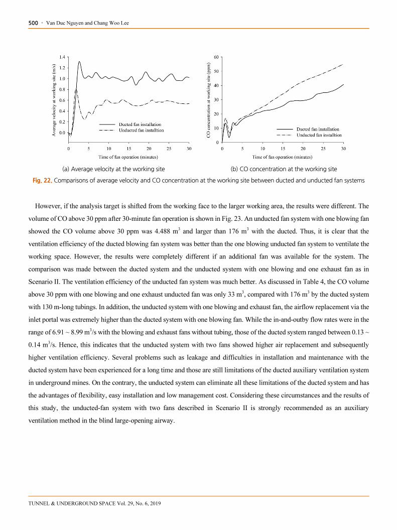
The average velocity and CO concentration at the working site observed during the simulation are compared in Fig. 22. It
can be seen that the ducted fan system showed higher average velocity, 0.95 m/s compared with 0.50 m/s by the unducted fan
system. Subsequently, CO concentration of 40 ppm was measured at the face by the ducted system and 55 ppm by the
unducted system.
500 ∙ Van Duc Nguyen and Chang Woo Lee
TUNNEL & UNDERGROUND SPACE Vol. 29, No. 6, 2019
(a) Average velocity at the working site (b) CO concentration at the working site
Fig. 22. Comparisons of average velocity and CO concentration at the working site between ducted and unducted fan systems
However, if the analysis target is shifted from the working face to the larger working area, the results were different. The
volume of CO above 30 ppm after 30-minute fan operation is shown in Fig. 23. An unducted fan system with one blowing fan
showed the CO volume above 30 ppm was 4.488 m3 and larger than 176 m3 with the ducted. Thus, it is clear that the
ventilation efficiency of the ducted blowing fan system was better than the one blowing unducted fan system to ventilate the
working space. However, the results were completely different if an additional fan was available for the system. The
comparison was made between the ducted system and the unducted system with one blowing and one exhaust fan as in
Scenario II. The ventilation efficiency of the unducted fan system was much better. As discussed in Table 4, the CO volume
above 30 ppm with one blowing and one exhaust unducted fan was only 33 m3, compared with 176 m3 by the ducted system
with 130 m-long tubings. In addition, the unducted system with one blowing and exhaust fan, the airflow replacement via the
inlet portal was extremely higher than the ducted system with one blowing fan. While the in-and-outby flow rates were in the
range of 6.91 ~ 8.99 m3/s with the blowing and exhaust fans without tubing, those of the ducted system ranged between 0.13 ~
0.14 m3/s. Hence, this indicates that the unducted system with two fans showed higher air replacement and subsequently
higher ventilation efficiency. Several problems such as leakage and difficulties in installation and maintenance with the
ducted system have been experienced for a long time and those are still limitations of the ducted auxiliary ventilation system
in underground mines. On the contrary, the unducted system can eliminate all these limitations of the ducted system and has
the advantages of flexibility, easy installation and low management cost. Considering these circumstances and the results of
this study, the unducted-fan system with two fans described in Scenario II is strongly recommended as an auxiliary
ventilation method in the blind large-opening airway.

Optimization of the Unducted Auxiliary Ventilation for Large-Opening Underground Limestone Mines ∙ 501
TUNNEL & UNDERGROUND SPACE Vol. 29, No. 6, 2019
(a) unducted-fan system with one blowing and one exhaust fan
(b) Ducted fan system with 130 m-long tubing
Fig. 23. Volume of CO above 30 ppm after 30-minute fan operation
4. SITE STUDY WITH A UNDUCTED FAN SYSTEM
4.1 Test of a unducted fan system at mine site
The ventilation efficiency of an unducted fan system was tested at a local large-opening limestone mine in Gangwon
province. Fig. 24 illustrates the test site where the whole working space is connected to the main haulage way by a single
airway. The 250 m-long straight segment of the dead-end entry is 10 m wide and 8 m high. As in Fig. 24, one free-standing
vane-axial 37-kW high-pressure fan was installed close to the sidewall to supply air to the working site, and the distance from
fan to the dead-end working face was about 120 m. Table 5 describes the characteristics of the fan used.
Fig. 24. Study site of an auxiliary unducted-fan in large-opening mine

502 ∙ Van Duc Nguyen and Chang Woo Lee
TUNNEL & UNDERGROUND SPACE Vol. 29, No. 6, 2019
Fig. 25. Auxiliary fan used for the test
Table 5. Characteristics of the fan used for the test
Description Fan characteristics
Type of fan Axial-vane fan
Capacity (m3/mim) 1.150
Pressure ( mmAq) 130
Speed (rpm) 1.786
Noise level (dB(A)) 103 ~ 105
Total Efficiency (%) 39.7
Power (kW) 37
Length (m) 3.450
Height (m) 0.91
Hot-wire anemometers were used to monitor the average velocity at several positions within the experiment site. Smoke
tubes were also used to identify the direction of airflow showing ultra-low velocity. Fig. 25 shows the unducted fan and
smoke tube measurement. Velocity measurements were shown in Fig. 26. The fan discharge velocity measured at the outlet
was 35 m/s. The air was supplied into the dead-end working area along the same side as the fan and was also flowing out
along the other side. The average inby and outby velocities measured near the working face were 0.05 m and 0.1 m/s,
respectively. The jet stream discharged from the fan lost a substantial portion of the kinetic energy due to the collision to the
sidewall. This indicates that installing a fan in proper manners is critical for determining the ventilation efficiency; the
location, discharge angle, installation height and the gap between fan and wall are some of those variables to take into
consideration to enhance the ventilation efficiency. There were two fixed stations to monitor the inby and outby air velocity at
both sides of the airway. The measurements are compared with the CFD analysis output in the subsequent section. The CFD
analysis conditions can be seen in Table 2.

Optimization of the Unducted Auxiliary Ventilation for Large-Opening Underground Limestone Mines ∙ 503
TUNNEL & UNDERGROUND SPACE Vol. 29, No. 6, 2019
Fig. 26. Velocity monitoring locations and measurement results in the test
4.2 CFD analysis of the ventilation efficiency
The aforementioned results indicated that the proper installation of the fan is critical to determining the ventilation
efficiency. Fig. 27 shows the CFD analysis for two cases: Case 1 for the same system as the site test and Case 2 with the fan
at a different location to assess its effect on the ventilation efficiency. In Case 2, the fan was moved to a location to minimize
(a) velocity distribution
(b) CO concentration
Fig. 27. Comparisons of the cases with different fan location
504 ∙ Van Duc Nguyen and Chang Woo Lee
TUNNEL & UNDERGROUND SPACE Vol. 29, No. 6, 2019
the possibility of collision of the jet stream with the airway sidewalls. In Case 1 where the jet stream generated from the fan
collied with the sidewall immediately after being discharged, its flow length colored red in the figure was shorter compared to
Case 2 where the fan was relocated to minimize the possibility of collision. Therefore, Case 2 clearly showed higher velocity
distribution near the working faces in Fig. 27. As predicted, higher velocity distribution in Case 2 led to lower CO
concentration throughout the working space.
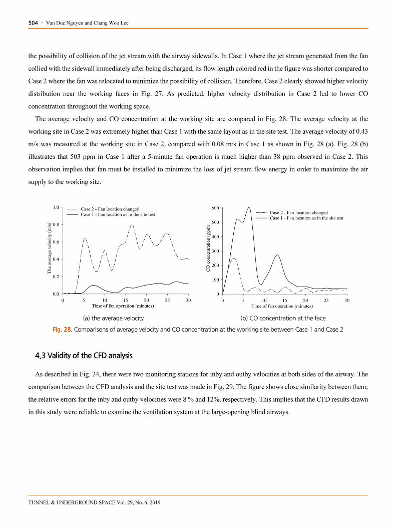
The average velocity and CO concentration at the working site are compared in Fig. 28. The average velocity at the
working site in Case 2 was extremely higher than Case 1 with the same layout as in the site test. The average velocity of 0.43
m/s was measured at the working site in Case 2, compared with 0.08 m/s in Case 1 as shown in Fig. 28 (a). Fig. 28 (b)
illustrates that 503 ppm in Case 1 after a 5-minute fan operation is much higher than 38 ppm observed in Case 2. This
observation implies that fan must be installed to minimize the loss of jet stream flow energy in order to maximize the air
supply to the working site.
(a) the average velocity (b) CO concentration at the face
Fig. 28. Comparisons of average velocity and CO concentration at the working site between Case 1 and Case 2
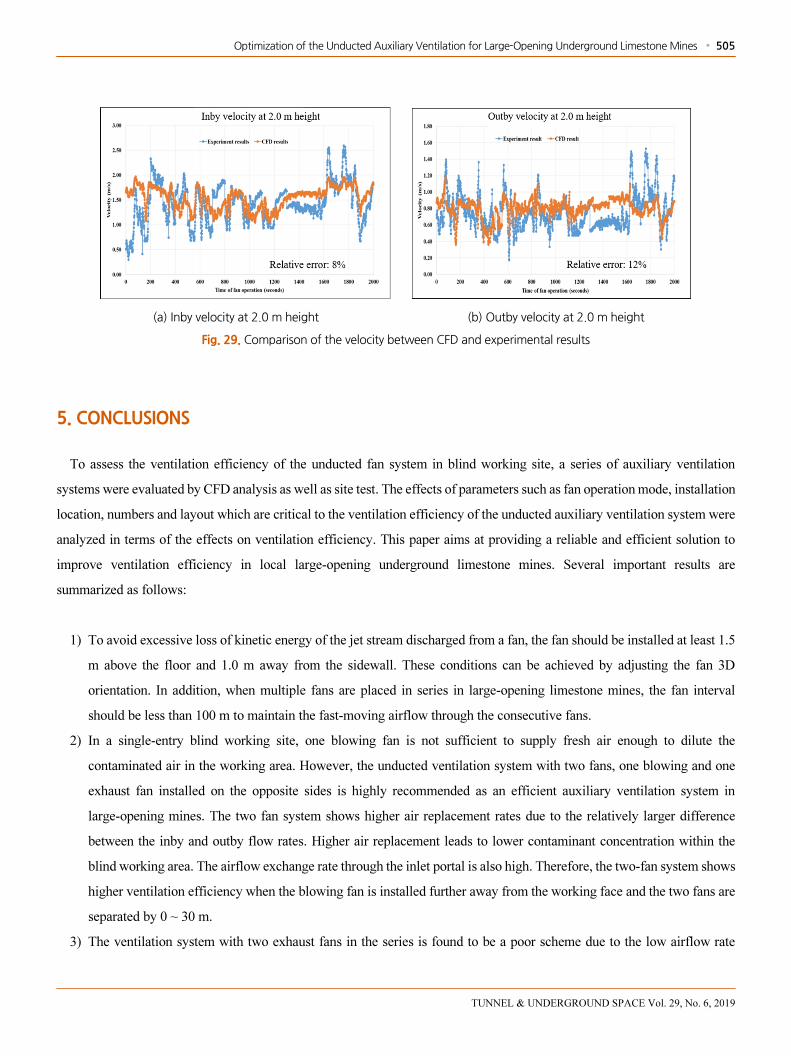
4.3 Validity of the CFD analysis
As described in Fig. 24, there were two monitoring stations for inby and outby velocities at both sides of the airway. The
comparison between the CFD analysis and the site test was made in Fig. 29. The figure shows close similarity between them;
the relative errors for the inby and outby velocities were 8 % and 12%, respectively. This implies that the CFD results drawn
in this study were reliable to examine the ventilation system at the large-opening blind airways.
Optimization of the Unducted Auxiliary Ventilation for Large-Opening Underground Limestone Mines ∙ 505
TUNNEL & UNDERGROUND SPACE Vol. 29, No. 6, 2019
(a) Inby velocity at 2.0 m height (b) Outby velocity at 2.0 m height
Fig. 29. Comparison of the velocity between CFD and experimental results
5. CONCLUSIONS
To assess the ventilation efficiency of the unducted fan system in blind working site, a series of auxiliary ventilation
systems were evaluated by CFD analysis as well as site test. The effects of parameters such as fan operation mode, installation
location, numbers and layout which are critical to the ventilation efficiency of the unducted auxiliary ventilation system were
analyzed in terms of the effects on ventilation efficiency. This paper aims at providing a reliable and efficient solution to
improve ventilation efficiency in local large-opening underground limestone mines. Several important results are
summarized as follows:
1) To avoid excessive loss of kinetic energy of the jet stream discharged from a fan, the fan should be installed at least 1.5
m above the floor and 1.0 m away from the sidewall. These conditions can be achieved by adjusting the fan 3D
orientation. In addition, when multiple fans are placed in series in large-opening limestone mines, the fan interval
should be less than 100 m to maintain the fast-moving airflow through the consecutive fans.
2) In a single-entry blind working site, one blowing fan is not sufficient to supply fresh air enough to dilute the
contaminated air in the working area. However, the unducted ventilation system with two fans, one blowing and one
exhaust fan installed on the opposite sides is highly recommended as an efficient auxiliary ventilation system in
large-opening mines. The two fan system shows higher air replacement rates due to the relatively larger difference
between the inby and outby flow rates. Higher air replacement leads to lower contaminant concentration within the
blind working area. The airflow exchange rate through the inlet portal is also high. Therefore, the two-fan system shows
higher ventilation efficiency when the blowing fan is installed further away from the working face and the two fans are
separated by 0 ~ 30 m.
3) The ventilation system with two exhaust fans in the series is found to be a poor scheme due to the low airflow rate

506 ∙ Van Duc Nguyen and Chang Woo Lee
TUNNEL & UNDERGROUND SPACE Vol. 29, No. 6, 2019
supplied to the face and low subsequent air replacement efficiency. Therefore, it leads to extremely high contaminant
concentration within the working environment. Hence, the system with two exhaust fans in the series can not be
recommended for the blind site auxiliary ventilation scheme.
4) The site experiment with one 37 kW blowing fan shows that the low efficiency of fan installation led to the low velocity
at the working site. The site study results show that fans must be placed to minimize the possibility of collision and
maintain the high velocity of the airflow. Acquiring a certain difference between the inby and outby air velocities is
critical to lower the contaminant level at the blind working sites. These results were well confirmed by the CFD
analysis.
5) Ventilating large-opening blind working sites is a difficult task without a properly designed and managed auxiliary
ventilation system. However, even with a well-engineered system, a low capital and maintenance cost system is also
required at local limestone mines. This study shows that low-cost unducted auxiliary ventilation system with two fans,
one blowing fan and one exhaust fan, can provide flexibility as well as high ventilation efficiency if designed correctly.
ACKNOWLEDGMENT
This research was supported by grants of “Development and On-site Demonstration of Smart ICT/IoT-Based Mining
Smart Ventilation System” (grant No. 20182510102380) funded by the Ministry of Trade Industrial and Energy of the Korean
government.
REFERENCES
ANSYS, Inc., 2019, FLUENT User’s Guide, Version 17.0, Canonsburg, PA: ANSYS, Inc.
Colella, F., Rein, G., Verda, V., Borchiellini, R., 2011, Multiscale modeling of transient flows from fire and ventilation in long
tunnels. Comput. Fluids 51, pp. 16-29.
Dunn, M, F. Kendorski, M. O. Rahim and J. Volkwein, 1983, Auxiliary Jet Fans and How to Get the Most Out of Them for
Ventilating Large Room-And-Pillar Mines, Engineering Mining Journal, Dec., pp. 31-34.
Gao, J., Uchino, K., Inoue, M., 2002, Simulation of thermal environmental conditions in heading face with forcing auxiliary
ventilation-control of thermal environmental conditions in locally ventilated working place (1st report). Min. Mater.
Process. Inst. Jpn. 118, pp. 9-16.
Gosman, A., 1999, Developments in CFD for industrial and environmental applications in wind engineering. J. Wind Eng. Ind.
Aerod. 81, pp. 21-39.
Grau III, R. H., Krog, R. B., Robertson, S. B, 2006, Maximizing the ventilation of large-opening mines, In Proceedings of the 11th
US/North American Mine Ventilation Symp. University Park, PA pp. 53-59.
Grau III, R. H., Mucho, T. P., Robertson, S. B., Smith, A. C., Garcia, F, 2002, Practical techniques to improve the air quality in

Optimization of the Unducted Auxiliary Ventilation for Large-Opening Underground Limestone Mines ∙ 507
TUNNEL & UNDERGROUND SPACE Vol. 29, No. 6, 2019
underground stone mines, In the North American/Ninth US Mine Ventilation Symposium, Kingston, Ontario, Canada, pp.
123-129.
Graul III, R. H., Krog, R, 2009, Using mine planning and other techniques to improve ventilation in large-opening mines. Mining
Engineering, 61(2), 46.
Haghighat, A. 2014, Analysis of a ventilation network in a multiple fans limestone mine. Missouri University of Science and
Technology.
Hargreaves, D., Lowndes, I.S., 2007, The computational modeling of the ventilation flows within a rapid development drivage.
Tunn. Undergr. Sp. Tech. 22, pp. 150-160.
Hartman, H.L., Mutmansky J.M., 2002, Introductory Mining Engineering, Published by John Wiley & Sons Inc., Hoboken, New
Jersey, Second Edition.
Huang, Yuandong, and Zhonghua Zhou., 2013, A numerical study of airflow and pollutant dispersion inside an urban street canyon
containing an elevated expressway, Environmental Modeling & Assessment 18.1, pp. 105-114.
Krog, R., Grau III, R., 2006, Fan selection for large-opening mines: vane-axial or propeller fans-which to choose?, Proceedings of
11th US, In North American Mine Ventilation Symposium, Pennsylvania, USA, pp. 527-534.
Lee, C. W., Nguyen, V.D., 2015, Development of a Low-Pressure Auxiliary Fan for Local Large-opening Limestone Mines.
Journal of Korean Society for Rock Mechanics, Tunnel and Underground Space, 25(6), pp. 543-555.
Migoya, E., Crespo, A., Hernández, J., 2009, A simplified model of fires in road tunnels. Comparison with three-dimensional
models and full-scale measurements. Tunn. Undergr. Sp. Tech. 24, pp. 37-52.
Montazeri, H., 2011, Experimental and numerical study on natural ventilation performance of various multi-opening wind catchers.
Build. Environ. 46, pp. 370-378.
Parra, M., Villafruela, J., Castro, F., Mendez, C., 2006, Numerical and experimental analysis of different ventilation systems in
deep mines. Build. Environ. 41, pp. 87-93.
Rafailidis, S., Schatzmann, M., 1995, Concentration Measurements with Different Roof Patterns in Street Canyon with Aspect
Ratios B/H¼1/2 and B/H¼1. Universität Hamburg, Meterologisches Institute.
Road design guidelines, chapter 6, 2010, Ministry of Land, Infrastructure and Transport, Republic of Korea.
Silvester, Stephen., 2002, The integration of CFD and VR methods to assist auxiliary ventilation practice. Ph.D. thesis, University
of Nottingham.
Toraño, J., Torno, S., Menendez, M., Gent, M., Velasco, J., 2009. Models of methane behaviour in auxiliary ventilation of
underground coal mining. Int. J. Coal Geol. 80, pp. 35-43.
Torno, S., Toraño, J., Ulecia, M., Allende, C., 2013, Conventional and numerical models of blasting gas behaviour in auxiliary
ventilation of mining headings. Tunn. Undergr. Sp. Tech. 34, pp. 73-81.
Wallace K.G., 2001, General Operational Characteristics and Industry Practices of Mine Ventilation Systems, Proceedings of the
7th International Mine Ventilation 149 Congress (Ed: S. Wasilewski), pp. 229-234, (Research and Development Centre for
Electrical Engineering and Automation in Mining, Cracow, Poland.
Zheng, Y., 2011, Diesel Particulate Matter Dispersion Analysis in Underground Metal/Nonmetal Mines Using Computational Fluid
Dynamics. Missouri University of Science and Technology, Missouri.
Zhongwei, W., Ting, R., 2013, Investigation of airflow and respirable dust flow behaviour above an underground bin. Powder
Technol. 250, pp. 103-114.