Embed Size (px)
Citation preview

Optics Communications 282 (2009) 18–21
Contents lists available at ScienceDirect
Optics Communications
journal homepage: www.elsevier .com/locate/optcom
Optimization of the operational bandwidth in air-core photonic bandgapfibers for IR transmission
Jonathan Hu *, Curtis R. MenyukDepartment of Computer Science and Electrical Engineering, University of Maryland Baltimore County, 5200 Westland Boulevard 205A, Baltimore, MD 21250, USA
a r t i c l e i n f o a b s t r a c t
Article history:Received 25 July 2008Received in revised form 9 September 2008Accepted 9 September 2008
Keywords:Fiber design and fabricationInfraredFiber properties
0030-4018/$ - see front matter � 2008 Elsevier B.V. Adoi:10.1016/j.optcom.2008.09.055
* Corresponding author. Tel.: +1 410 455 6507; faxE-mail address: [email protected] (J. Hu).
We determine the optimal inner glass ring thickness in infrared air-core photonic bandgap fibers (PBGFs)with 19-cell and 7-cell cores. For PBGFs with a 19-cell core, we find that an inner ring thickness of 0:04 K,where K is pitch, yields the widest operational bandwidth, which is nearly 6%. The operational band-width increases as the refractive index decreases from 2.8 to 2.0. For PBGFs with a 7-cell core, one needsto draw fiber with a ring thickness of less than 0:03 K to achieve a comparable operational bandwidth.
� 2008 Elsevier B.V. All rights reserved.
1. Introduction
Air-core photonic bandgap fibers (PBGFs), in contrast to someother types of holey fiber, guide light through the photonic band-gap effect, instead of using total internal reflection [1]. These air-core PBGFs have the potential to provide very low-loss transmis-sion, along with delivery of high-powers and low-nonlinearity.
Surface modes, which are located between the core and clad-ding, have been shown to have a significant impact on the loss ofthe fundamental mode [2,3]. Amezcua-Correa et al. [4–6] demon-strated that by carefully selecting the thickness of the inner glassring around the core, it is possible to push the surface modes awayfrom the center of the bandgap in silica PBGFs. Laser-power deliv-ery in infrared (IR) region through optical fibers has important mil-itary and medical applications [7,8]. Pearce et al. [9] showed that aPBGF with a 19-cell core and a glass refractive index of 2.4 has anoperational bandwidth of 5% of the center frequency with an innerglass ring thickness of 0:05 K, where the pitch, K, is defined as thedistance between the centers of the nearby holes. However, this re-sult does not indicate what parameter choice optimizes the band-width. In this paper, we study the operational bandwidth as afunction of inner glass ring thickness for PBGFs with differentrefractive indices for the glasses used for IR transmission. We ana-lyze fibers with both a 19-cell and a 7-cell core. These geometrieswere previous studied [4,9]. The optimum inner glass ring thicknessthat yields the widest operational bandwidth is 0:04 K. We considernon-silica glasses that have a refractive index between 2.0 and 2.8[10]. The operational bandwidth increases when the refractive in-
ll rights reserved.
: +1 410 455 6500.
dex decreases from 2.8 to 2.0, which is slightly larger than the rangeof possible values of chalcogenide glass used for IR transmission [7].
2. Fiber geometry
We calculate the fiber modes and their propagation constantsusing Comsol Multiphysics, a commercial full-vector mode solverbased on the finite-element method. Anisotropic perfectly-matched layers (PMLs) [11] are positioned outside the outermostring of holes in order to reduce the simulation window for a PBGFwith five air-hole rings. To validate our simulations, we comparedour results to Fig. 3 of Ref. [4], and we obtained agreement. Fig. 1shows the fiber core geometries for two air-core PBGFs. The coreis created by introducing a larger air hole at the center of the fiber.Only a quarter of the geometry is used in modeling PBGFs becauseof the symmetry of the fundamental core mode. Modes of othersymmetry classes do exist within the bandgap, but it is expectedthat they will have little impact on the usable bandwidth. Fig. 1aand b correspond to a 19-cell and 7-cell core, meaning that 19and 7 air holes have been removed, respectively, to form the corebefore the drawing process. In this study we use D=K ¼ 0:8 forboth 19-cell and 7-cell cores, which has been shown to yield a widebandgap for high-index glass [12]. In Fig. 1a, the corner of the innerglass ring is rounded with radius dp, where dp=K ¼ 0:5. In Fig. 1b,we use dp=K ¼ 0:2. The corner of the core region is rounded withradius dc, where dc=K ¼ 0:94.
3. Result and analysis
When there is no coupling loss due to surface modes, the over-all attenuation is dominated by scattering loss due to surface
a b
Λ/2 Λ/2 Λ Λ
Fig. 1. Fiber geometries for PBGFs with (a) a 19-cell core and (b) a 7-cell core.
J. Hu, C.R. Menyuk / Optics Communications 282 (2009) 18–21 19
roughness. This loss factor F can be estimated from the field inten-sity at the air–glass interfaces as [13]
F ¼ �0
l0
� �1=2H
hole perimeters dljEj2Rcross-section dAðE�H�Þ � z
�� �� ; ð1Þ
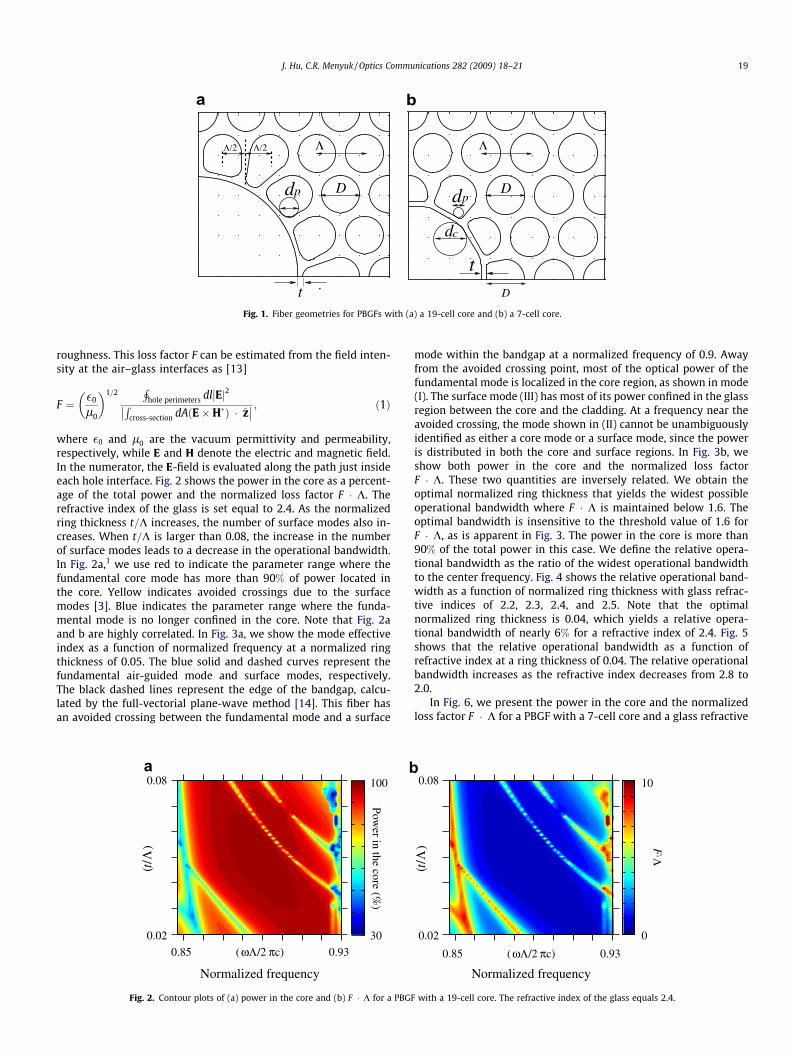
where �0 and l0 are the vacuum permittivity and permeability,respectively, while E and H denote the electric and magnetic field.In the numerator, the E-field is evaluated along the path just insideeach hole interface. Fig. 2 shows the power in the core as a percent-age of the total power and the normalized loss factor F � K. Therefractive index of the glass is set equal to 2.4. As the normalizedring thickness t=K increases, the number of surface modes also in-creases. When t=K is larger than 0.08, the increase in the numberof surface modes leads to a decrease in the operational bandwidth.In Fig. 2a,1 we use red to indicate the parameter range where thefundamental core mode has more than 90% of power located inthe core. Yellow indicates avoided crossings due to the surfacemodes [3]. Blue indicates the parameter range where the funda-mental mode is no longer confined in the core. Note that Fig. 2aand b are highly correlated. In Fig. 3a, we show the mode effectiveindex as a function of normalized frequency at a normalized ringthickness of 0.05. The blue solid and dashed curves represent thefundamental air-guided mode and surface modes, respectively.The black dashed lines represent the edge of the bandgap, calcu-lated by the full-vectorial plane-wave method [14]. This fiber hasan avoided crossing between the fundamental mode and a surface
0.08
0.02
0.85 0.93
Normalized frequency
ωΛ π( /2 c)
100
30
a
Λt( /
)
Power in the core (%
)
b
Fig. 2. Contour plots of (a) power in the core and (b) F � K for a PBGF
mode within the bandgap at a normalized frequency of 0.9. Awayfrom the avoided crossing point, most of the optical power of thefundamental mode is localized in the core region, as shown in mode(I). The surface mode (III) has most of its power confined in the glassregion between the core and the cladding. At a frequency near theavoided crossing, the mode shown in (II) cannot be unambiguouslyidentified as either a core mode or a surface mode, since the poweris distributed in both the core and surface regions. In Fig. 3b, weshow both power in the core and the normalized loss factorF � K. These two quantities are inversely related. We obtain theoptimal normalized ring thickness that yields the widest possibleoperational bandwidth where F � K is maintained below 1.6. Theoptimal bandwidth is insensitive to the threshold value of 1.6 forF � K, as is apparent in Fig. 3. The power in the core is more than90% of the total power in this case. We define the relative opera-tional bandwidth as the ratio of the widest operational bandwidthto the center frequency. Fig. 4 shows the relative operational band-width as a function of normalized ring thickness with glass refrac-tive indices of 2.2, 2.3, 2.4, and 2.5. Note that the optimalnormalized ring thickness is 0.04, which yields a relative opera-tional bandwidth of nearly 6% for a refractive index of 2.4. Fig. 5shows that the relative operational bandwidth as a function ofrefractive index at a ring thickness of 0.04. The relative operationalbandwidth increases as the refractive index decreases from 2.8 to2.0.
In Fig. 6, we present the power in the core and the normalizedloss factor F � K for a PBGF with a 7-cell core and a glass refractive
Λt( /
)
0.08
0.02
0.85 0.93
Normalized frequency
ωΛ π( /2 c)
0
F.Λ
10
with a 19-cell core. The refractive index of the glass equals 2.4.

band
wid
th (
%)
7
Rel
ativ
e op
erat
iona
l
2.8n
1.84
Fig. 5. The relative operational bandwidth for different glass refractive indices witha normalized ring thickness of 0.04.
0.84 0.93ωΛ π( /2 c)
Normalized frequency
Eff
ectiv
e in
dex
1
II
III
I
0.97
(I) (II) (III)
1.0
0
c
0
100
0.84 0.93ωΛ π( /2 c)
ΛF
0
Normalized frequency
12
Pow
er in
the
core
(%
)
Fig. 3. (a) The mode effective index as a function of normalized frequency at anormalized ring thickness of 0.05. The blue solid and dashed curves represent thefundamental air-guided mode and surface modes, respectively. The black dashedlines represent the edge of the bandgap. (b) The comparison between power in thecore and normalized factor F � K for a PBGF with a 19-cell core. Black dash-dottedline indicates F � K ¼ 1:6. (c) The relative mode intensity profiles correspond topoints I, II, and III in (a).
Normalized ring thickness
2
band
wid
th (
%)
( /Λ )t
7
0.02 0.06
2.2n=2.3
2.42.5
Rel
ativ
e op
erat
iona
l
Fig. 4. Relative operational bandwidth as a function of normalized ring thickness.
20 J. Hu, C.R. Menyuk / Optics Communications 282 (2009) 18–21
index of 2.4. In this case, when the normalized ring thickness is lessthan 0.05, the relative operational bandwidth increases as the nor-malized ring thickness decreases. The relative operational band-width is higher than 6% when the normalized ring thickness is
0.08
0.02 30
100
0.920.84 (ωΛ/2πc)
Normalized frequency
Power in the core (%
)
( /
)tΛ
a
Fig. 6. Contour plots of (a) power in the core a
less than 0.03. Such a small ring thickness may be difficult to drawin practice.
4. Conclusion
For PBGFs with a 19-cell core, a normalized ring thickness of0.04 yields the widest operational bandwidth, which is nearly6%. The operational bandwidth increases as the refractive indexdecreases from 2.8 to 2.0. For PBGFs with a 7-cell core, one must
(ωΛ/2πc)
0.08
0.020.84
0
0.92
Normalized frequency
F.Λ
8
( /
)tΛ
b
nd (b) F � K for a PBGF with a 7-cell core.

J. Hu, C.R. Menyuk / Optics Communications 282 (2009) 18–21 21
draw fiber with a ring thickness of less than 0:03 K to achieve acomparable operational bandwidth.
Acknowledgements
The authors would like to thank Rodrigo Amezcua-Correa forhelping us to compare his group’s simulation results to ours. Thiswork has been partially supported by the Naval ResearchLaboratory.
References
[1] J. Broeng, S.E. Barkou, T. Sondergaard, A. Bjarklev, Opt. Lett. 25 (2000) 96.[2] K. Saitoh, N. Mortensen, M. Koshiba, Opt. Express 12 (2004) 394.[3] J. West, C. Smith, N. Borrelli, D. Allan, K. Koch, Opt. Express 12 (2004) 1485.
[4] R. Amezcua-Correa, N.G. Broderick, M.N. Petrovich, F. Poletti, D.J. Richardson,Opt. Express 14 (2006) 7974.
[5] R. Amezcua-Correa, N.G. Broderick, M.N. Petrovich, F. Poletti, D.J. Richardson,Opt. Express 15 (2007) 17577.
[6] R. Amezcua-Correa, F. Gèrôme, S.G. Leon-Saval, N.G.R. Broderick, T.A. Birks, J.C.Knight, Opt. Express 16 (2008) 1142.
[7] J.S. Sanghera, I.D. Aggarwal, L.E. Busse, P.C. Pureza, V.Q. Nguyen, F.H. Kung, L.B.Shaw, F. Chenard, Laser Focus World 41 (2005) 83.
[8] C. Anastassiou, G. Dellemann, O. Weisberg, U. Kolodny, Photon. Spectra 38(2004) 108.
[9] G. Pearce, J. Pottage, D. Bird, P. Roberts, J. Knight, P.J. Russell St, Opt. Express 13(2005) 6937.
[10] X. Feng, A.K. Mairaj, D.W. Hewak, T.M. Monro, J. Lightwave Technol. 23 (2005)2046.
[11] K. Saitoh, M. Koshiba, Opt. Express 11 (2003) 3100.[12] J. Hu, C.R. Menyuk, Opt. Express 15 (2007) 339.[13] P. Roberts, F. Couny, H. Sabert, B. Mangan, D. Williams, L. Farr, M. Mason, A.
Tomlinson, T. Birks, J. Knight, P.J. Russell St, Opt. Express 13 (2005) 236.[14] S. Johnson, J. Joannopoulos, Opt. Express 8 (2001) 173.