Embed Size (px)
Citation preview

Journal of Research in Science, Technology, Engineering and Management (JoRSTEM) Volume. 2, issue: 1, March -2016
14 © Malla Reddy Engineering College (Autonomous)
Optimization of sheet metal forming process based on Sobal sampling
Yogeshkumar D. Dhankani1, Shripad Kamlakar2, Anil Mashalkar2, Deepak Dhole3
1M.Tech Student, Walchand College of Engineering Sangli-416415 (MH), India
23dPLM Software Solutions Ltd Pune-411057 (MH), India
[email protected] [email protected]
3Adjunct Professor Walchand College of Engineering
Sangli-416415 (MH), India [email protected]
Abstract— One of the most common industrial processes in sheet metal forming is deep drawing. Deep drawing process is a manufacturing process in which a sheet metal work piece is pressed into a die cavity such that stress induced on sheet is greater than its yield stress but less than ultimate tensile stress. The aim of successful deep drawing process is to produce a product with required final depth as well as with fewer defects. This study involves simulation of deep drawing process considering various parameters like blank holding force, punch and die corner radius and their effect on thinning rate of blank with constraints of wrinkle, rupture and stretching. In order to minimize impact of the variations and achieve reliable process parameters, robust design models for sheet metal forming process integrated sobal sampling with response surface method. A cup drawing example was employed to verify the feasibility of the proposed method. Rectangular cup model was made in 3DExperience (3DX) physics app using Catia simulation model preparation design and design space of input parameters was created using workflow with DOE (Design of Experiment) adapter in process composer. Response surface in high dimensional space was fitted to describe the mapping relations between an input and output parameters. The response surface could be used as the surrogate predictive models during optimization processes. Comparisons were conducted between different optimization models to demonstrate robustness of the sobal sampling method.
Keywords: Deep Drawing, Sobal sampling, Response surface method, 3DExperience, Design of experiment.
1. INTRODUCTION
Sheet metal forming processes is primarily used to produce a desired shape by plastic deformation. The final product quality is dependent on both the sheet material characteristics and process variables such as strain, strain rate, friction and temperature. Sheet metal forming operations consists of simple bending, ironing, stretch forming, roll forming, stamping, flanging, spinning, embossing, hyperplastic forming, peen forming, explosive forming, magnetic-pulse forming, bending and deep drawing of complex parts. The commonest sheet metal forming process is deep drawing. In deep drawing process sheet metal blank is drawnradiallyby the mechanical action of a punch into a forming die, so metal sheet is subjected to tensile and compressive stresses. This process allows obtaining a complex shape part through a simple process based on the plastic deformation of the metallic sheet. It can fabricate a variety of objects with cylindrical cups, rectangular cups even complex shapes. Some of deep drawn components are kitchen utensils, beverage cans, automobile bodies, aircraft panels, construction and farming equipments. Major advantage of deep drawing process is that grain orientation is possible and that to with less wastage of material.
Journal of Research in Science, Technology, Engineering and Management (JoRSTEM) Volume. 2, issue: 1, March -2016
15 © Malla Reddy Engineering College (Autonomous)
Deep drawing typically faces difficulties or challenges associated with earing, wrinkling, thinning and fracture all of which are expensive as they lead to wastage of material and loss of production time. Simulation can predict such defects during product development and often prevent their occurrence during production with the attendant saving time and material, by identifying necessary and often times simple changes in design. Also determination of the effect of the process parameters on the final forming quality is very difficult in sheet metal forming process because forming process experience very complicated deformation. These process parameters have to be determined for the optimum forming condition before the process design. Conventional method to determine optimum process parameter is time consuming and costly. To address these shortcomings, sheet metal forming simulations have been applied instead. [1]
Design of experiment a data collection methodthen followed by approximation using response surface methodology used to help determine the relationship between different factors that affect a process and its output, were initially adopted in sheet metal forming process optimization. Browne and Hillery investigated variations and effects of punch and die geometry, blank-holding pressure, top-ram pressure, lubrication and drawing speed in the deep-drawing of steel cups of 0.9mm thickness by using DOE. Screening experiment was conducted and the desired factors were varied at different levels to achieve optimum solution. [2]
Kim and Hong did FEM based simulation on multistage deep drawing of Molybdenum sheet. They selected the die design variables like punch and die radius and die angle to find the most reliable multi-stage process. They used Hooke-Jeeve method of optimization to find local optima from the pool of solutions and simulated annealing approach of optimization to find the global optimum solution. [3]
Li et al. developed a CAE-based six sigma robust design method. Statistical techniques and dual response surface approximate model were integrated to perform robust design of deep drawing process of a rectangular cup. Even though the above methods have been applied in the robust design of sheet metal forming processes, the optimization model still needs to be improved to enhance the prediction accuracy of both approximation models and constraint evaluations. In this paper a sobal sampling method is proposed to integrate with response surface methodology in order to perform robust design for sheet metal forming process. [4]
Kawka et al. find wrinkling of conical cups and simulated using the finite element method (FEM) and verified experimentally. Two different FEM codes: static-explicit ITAS3D and dynamic-explicit ABAQUS/Explicit they used in numerical simulations. They found that several parameters could affect results of wrinkling simulation. Most important was the initial shape of the finite element mesh. General difficulties in simulation were reported for both FEM codes, dynamic and static. Stamping of conical cups was conducted using an anisotropic steel sheet to establish a reference frame for the validation of numerical results. Their result showed that the FEM results for both codes appeared to be very sensitive to the blank mesh. [5]
II. MODELING OF DEEP DRAWING
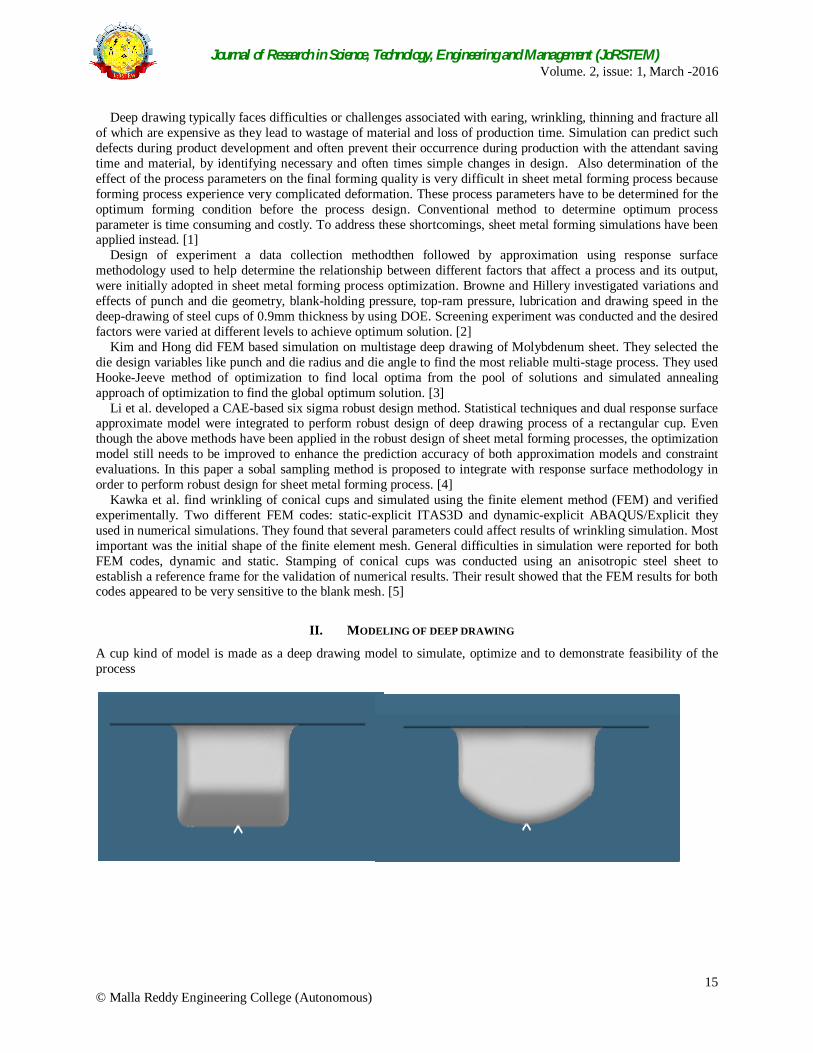
A cup kind of model is made as a deep drawing model to simulate, optimize and to demonstrate feasibility of the process
Journal of Research in Science, Technology, Engineering and Management (JoRSTEM) Volume. 2, issue: 1, March -2016
16 © Malla Reddy Engineering College (Autonomous)
Figure 1: Cup shape deep drawn part
Above figure is the product made for deep drawing. Before to manufacture product it is useful to carry its virtual simulation or to create a surrogate model which predicts effect of variation of input parameters on model so that cost and time could be saved. 3DX is a platform which consists of many inbuilt software applications. Few of those applications are physics app, process composer, performance study and result analytics that can be used for modeling and simulation. From the above model, a dimension of blank is calculated first by comparing surface area of model and blank. And then from holder are made as a rigid body while blank is deformable. All different modeled and meshed parts are assembled together in Catia Assembly Design. After that to create constraints and apply loads and boundary conditions Simulia Mechanical Scenario Creation app is used. Coefficient of friction is 0.125. Die is kept as fixed and punch is allowed displacement in only Z direction. Load is applied on blank holder which is later treated as one of input parameter and output request for displacement, stress, thickness, strain and velocity graph is defined.blank dimension dimensions of punch, die and blank holder are calculated. Each part of deep drawing is modeled separately in Catia simulation model preparation using 3DX. Each of above part is created in shell element. Then each part is meshed separately in Simulia mesh creation app. S4R quadratic node element is used with finer mesh for blank for better results. Punch, Die and Blank. Steel is used as material for product withmaterial properties shown in Table 1:
TABLE 1: PROPERTIES OF STEEL MATERIAL USED
E (MPa)
K (MPa)
N R0 R45 R90 Density (Kg/m3)
µ
2.1 E+5 543.56 0.255 2.098 2.12 2.569 7800 0.3
Hill anisotropy yield criterion was used to model the material behavior of steel in drawing cup part and the
material hardening curve is given by y = k (Ɛyp + Ɛp)^n, where Ɛp is the effective plastic strain and Ɛyp is the elastic strain at initial yield and anisotropic yield stress ratios are given by,
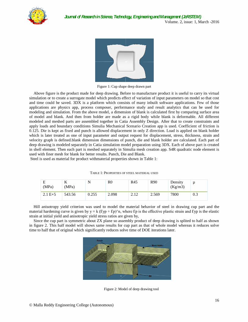
Since the cup part is symmetric about ZX plane so assembly product of deep drawing is splited to half as shown in figure 2. This half model will shows same results for cup part as that of whole model whereas it reduces solve time to half that of original which significantly reduces solve time of DOE iterations later.
Figure 2: Model of deep drawing tool
Journal of Research in Science, Technology, Engineering and Management (JoRSTEM) Volume. 2, issue: 1, March -2016
17 © Malla Reddy Engineering College (Autonomous)
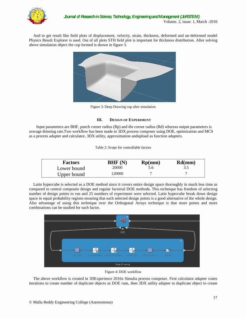
And to get result like field plots of displacement, velocity, strain, thickness, deformed and un-deformed model Physics Result Explorer is used. Out of all plots STH field plot is important for thickness distribution. After solving above simulation object the cup formed is shown in figure 3.
Figure 3: Deep Drawing cup after simulation
III. DESIGN OF EXPERIMENT
Input parameters are BHF, punch corner radius (Rp) and die corner radius (Rd) whereas output parameters is average thinning rate.Two workflow has been made in 3DX process composer using DOE, optimization and MCS as a process adapter and calculator, 3DX utility, approximation andupload as function adapters.
Table 2: Scope for controllable factors
Factors BHF (N) Rp(mm) Rd(mm) Lower bound 20000 5.6 3.5
Upper bound 120000 7 7 Latin hypercube is selected as a DOE method since it covers entire design space thoroughly in much less time as
compared to central composite design and regular factorial DOE methods. This technique has freedom of selecting number of design points to run and 25 numbers of experiment were selected. Latin hypercube break down design space in equal probability regions ensuring that each selected design points is a good alternative of the whole design. Also advantage of using this technique over the Orthogonal Arrays technique is that more points and more combinations can be studied for each factor.
Figure 4: DOE workflow
The above workflow is created in 3DExperience 2016x Simulia process composer. First calculator adapter crates iterations to create number of duplicate objects as DOE runs, then 3DX utility adapter to duplicate object to create
Journal of Research in Science, Technology, Engineering and Management (JoRSTEM) Volume. 2, issue: 1, March -2016
18 © Malla Reddy Engineering College (Autonomous)
new simulation object with parameters as defined in each DOE iteration after that 3DX utility to execute simulation i.e. to solve duplicated simulation object then 3DX utility to save simulation results to extract field plot images from simulation generated then calculator adapter to calculate thinning rate of the solved part and last upload adapter to upload simulation result STH field plot image file
Results obtained from above process are shown in figure 5.
Figure 5: Results of DOE iterations
IV. APPROXIMATE IMPLEMENTATION
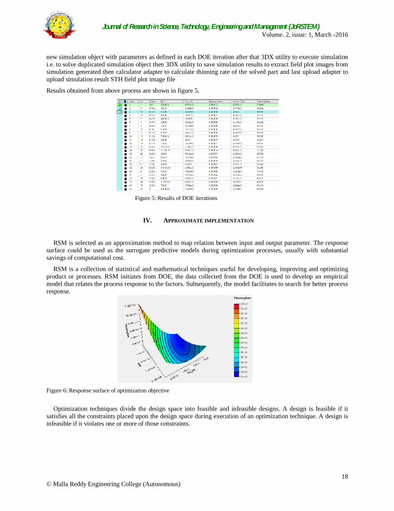
RSM is selected as an approximation method to map relation between input and output parameter. The response surface could be used as the surrogate predictive models during optimization processes, usually with substantial savings of computational cost.
RSM is a collection of statistical and mathematical techniques useful for developing, improving and optimizing product or processes. RSM initiates from DOE, the data collected from the DOE is used to develop an empirical model that relates the process response to the factors. Subsequently, the model facilitates to search for better process response.
Figure 6: Response surface of optimization objective
Optimization techniques divide the design space into feasible and infeasible designs. A design is feasible if it
satisfies all the constraints placed upon the design space during execution of an optimization technique. A design is infeasible if it violates one or more of those constraints.
Journal of Research in Science, Technology, Engineering and Management (JoRSTEM) Volume. 2, issue: 1, March -2016
19 © Malla Reddy Engineering College (Autonomous)
Figure 7: Optimization Workflow
Table 3: Optimization Results
Sr.NO. Parameters NLPQL 1 Blank Holding Force (N) 70000 2 Punch radius (mm) 5.6 3 Die radius (mm) 6.2
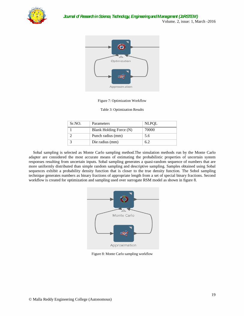
Sobal sampling is selected as Monte Carlo sampling method.The simulation methods run by the Monte Carlo
adapter are considered the most accurate means of estimating the probabilistic properties of uncertain system responses resulting from uncertain inputs. Sobal sampling generates a quasi-random sequence of numbers that are more uniformly distributed than simple random sampling and descriptive sampling. Samples obtained using Sobal sequences exhibit a probability density function that is closer to the true density function. The Sobol sampling technique generates numbers as binary fractions of appropriate length from a set of special binary fractions. Second workflow is created for optimization and sampling used over surrogate RSM model as shown in figure 8.
Figure 8: Monte Carlo sampling workflow
Journal of Research in Science, Technology, Engineering and Management (JoRSTEM) Volume. 2, issue: 1, March -2016
20 © Malla Reddy Engineering College (Autonomous)
Table 4: Sampling Results
V. RESULTS AND DISCUSSION
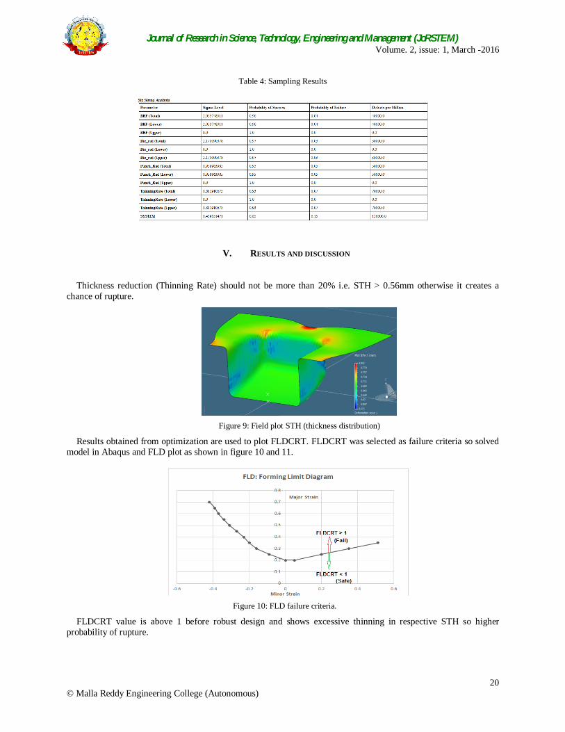
Thickness reduction (Thinning Rate) should not be more than 20% i.e. STH > 0.56mm otherwise it creates a chance of rupture.
Figure 9: Field plot STH (thickness distribution)
Results obtained from optimization are used to plot FLDCRT. FLDCRT was selected as failure criteria so solved model in Abaqus and FLD plot as shown in figure 10 and 11.
Figure 10: FLD failure criteria.
FLDCRT value is above 1 before robust design and shows excessive thinning in respective STH so higher probability of rupture.
Journal of Research in Science, Technology, Engineering and Management (JoRSTEM) Volume. 2, issue: 1, March -2016
21 © Malla Reddy Engineering College (Autonomous)
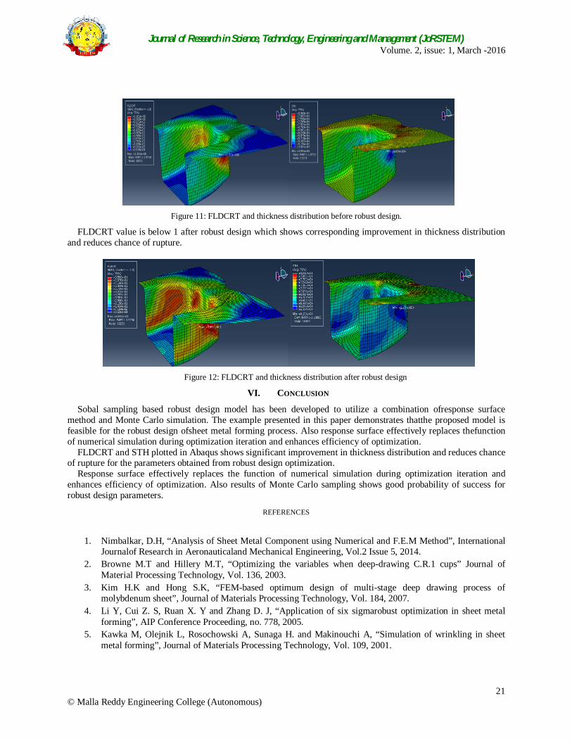
Figure 11: FLDCRT and thickness distribution before robust design.
FLDCRT value is below 1 after robust design which shows corresponding improvement in thickness distribution and reduces chance of rupture.
Figure 12: FLDCRT and thickness distribution after robust design
VI. CONCLUSION
Sobal sampling based robust design model has been developed to utilize a combination ofresponse surface method and Monte Carlo simulation. The example presented in this paper demonstrates thatthe proposed model is feasible for the robust design ofsheet metal forming process. Also response surface effectively replaces thefunction of numerical simulation during optimization iteration and enhances efficiency of optimization.
FLDCRT and STH plotted in Abaqus shows significant improvement in thickness distribution and reduces chance of rupture for the parameters obtained from robust design optimization.
Response surface effectively replaces the function of numerical simulation during optimization iteration and enhances efficiency of optimization. Also results of Monte Carlo sampling shows good probability of success for robust design parameters.
REFERENCES
1. Nimbalkar, D.H, “Analysis of Sheet Metal Component using Numerical and F.E.M Method”, International
Journalof Research in Aeronauticaland Mechanical Engineering, Vol.2 Issue 5, 2014. 2. Browne M.T and Hillery M.T, “Optimizing the variables when deep-drawing C.R.1 cups” Journal of
Material Processing Technology, Vol. 136, 2003. 3. Kim H.K and Hong S.K, “FEM-based optimum design of multi-stage deep drawing process of
molybdenum sheet”, Journal of Materials Processing Technology, Vol. 184, 2007. 4. Li Y, Cui Z. S, Ruan X. Y and Zhang D. J, “Application of six sigmarobust optimization in sheet metal
forming”, AIP Conference Proceeding, no. 778, 2005. 5. Kawka M, Olejnik L, Rosochowski A, Sunaga H. and Makinouchi A, “Simulation of wrinkling in sheet
metal forming”, Journal of Materials Processing Technology, Vol. 109, 2001.