Embed Size (px)
Citation preview
Jurnal Mekanikal
June 2015, Vol 38, 106-121
106
OPTIMIZATION OF RACING SERIES HYBRID
ELECTRIC VEHICLE USING DYNAMIC PROGRAMMING
Zainab Asus 1, 2, *
, El-Hassane Aglzim 2, Daniela Chrenko
2,
Zul-Hilmi Che-Daud 1, 2
and Luis Le-Moyne 2
1 Faculty of Mechanical Engineering,
Universiti Teknologi Malaysia,
81310 UTM, Johor, Malaysia
2
DRIVE Laboratory, Institut Supérieur de l’Automobile et des Transports (ISAT),
University of Burgundy,
49 rue Mlle Bourgeois,
58027 Nevers, France.
ABSTRACT
This paper discusses modeling of a racing series hybrid electric vehicle called Noao.
This plug-in hybrid system is equipped with an engine/generator set as its range extender.
The battery acts as the prime mover to propel the vehicle. Available applications of
control strategies for hybrid vehicle system in the literature are reviewed to identify a
suitable solution for its optimization. The behavior of the system and all of its components
are modeled in simulation and validated through experiments performed on the real
racing circuit. A dynamic programming approach is applied offline to optimize the
existing rule based control parameters defined for this racing car application. The same
approach is implemented to adjust the engine operating point in order to achieve a
longer endurance and to have a better performance.
Keywords: racing car; series hybrid electric vehicle; engine/battery; dynamic
programming optimization
1.0 INTRODUCTION
Hybrid electric vehicle (HEV) system appears as one of the most viable technologies
with significant potential to reduce fuel consumption and pollutant emissions within
realistic economical, infrastructural, and customer acceptance constraints. It possesses
new degrees of freedom to deliver power, thanks to presence of its reversible energy
storage system (ESS) that offer capability of idle off, regenerative braking, power assist,
and engine downsizing [1], [2]. It also has higher fuel efficiency and can achieve better
performance than a conventional vehicle [3], [4].
The design of HEV system architecture is complex, and the power management is
complicated due to a high degree of control flexibility, non-linear and multi-domain
components organization. So, an appropriate energy management is necessary to
coordinate its multiple energy sources and converters to obtain maximum energy
efficiency and optimize its potential [1], [5], [6].
The vehicle studied in this paper is a result of a collective work by the experts and
specialists of racing car application around Magny-Cours circuit industrial site [7], [8].
______________________________________
*Corresponding author: [email protected]
Jurnal Mekanikal June 2015
107
They use their expertise and experiences to build the car and define its control
parameters. They adopt a heuristic approach of rule based method to control the amount
of power given by the battery and the power generated by the engine/generator (EG) set
which is easily implemented in real vehicle by using a set of deterministic rules or fuzzy
rules.
There are two methods of control strategies; the rule based method and the
optimization method. The rule based (RB) power management strategy is based on
engineering intuition and simple analysis on component efficiency tables or charts [9],
[10], [11]. It is robust, has less computational load, and is effective in real-time
supervisory control of power flow in a hybrid drive-train [5], [12], [13], [14], [15]. It can
achieve near optimal solution, but it may fail to fully exploit potentials of HEV
architecture [2], [4], [12], [14]. It also cannot be easily implemented to another vehicle or
driving cycle due to lack of formal optimization and generalization [2].
The optimization based control methods can be local, global, real-time, and
parameter or threshold optimization. It can provide generality and reduce heavy tuning of
control parameters [16]. Optimization based controllers main task is to minimize a cost
function which is derived based on the vehicle and component parameters, and also the
performance expectations of the vehicle [4].
Global optimization approach can find a global optimum solution over a fixed
driving cycle and known future driving conditions to determine power distribution of
each system, make it unsuitable for a real time vehicle control [5], [16], [17], [18]. It
requires heavy computation and usually used for offline simulation applications as a
design tool to analyze, assess, and adjust other control strategies for online
implementation [3], [4], [5], [15]. The example of this method is Dynamic Programming
(DP), Genetic Algorithm (GA), and Direct Algorithm.
Real time optimization minimizes a cost function at each instant that depends only
upon the system variables at the current time which have been developed using the
system past information. It has limits on knowledge of future driving conditions and the
electrical path self-sustainability causing the solution to be not global optimal [4], [5],
[16]. The common method are the optimal control theory [19], [20] and the equivalent
consumption minimization strategy (ECMS) [3], [10], [21]. The ECMS is mostly utilized
because it only relies on the equivalence factor (EF) to solve the optimization problem
[21].
In this work, DP optimization method is chosen for this Noao car. This method has
never been utilized to optimize a racing type vehicle. The complete driving schedule is
obtained from the experiment carried out at Magny-Cours racing circuit in France. A
global optimization can be done because a precise specification of all components is
available.
DP is chosen over other approaches because it has established a reputation as the
benchmark of other strategies with its global optimum solution [1], [14], [22]. And it is
chosen over multi-objective GA trade-off solution since minimization of pollutant
emissions is not one of the focuses of this optimization.
The target of the control is to deplete the state of charge (SOC) of the battery from its
high initial SOC at the start of the race and reach a low limit of final SOC after a number
of turns at the end of the race. The objective of this study is to optimize the power split of
both power sources in order to minimize the system power losses and improve energy
efficiency through regenerative braking and power assist. The results are then utilized to
adjust the control parameters to achieve the objective and improve the car endurance and
enhance its performance.
The next part of this paper introduces the vehicle and its components. It is followed
by an explanation of the DP algorithm of dynamic programming used for the case studies,
Jurnal Mekanikal June 2015
108
which results will be analyzed in the results and discussion part, and finally the
conclusion in the last part.
2.0 VEHICLE MODEL
The Noao car used in this work is a series hybrid electric racing car system developed by
the Association des Entreprises Pôle de la Performance Nevers Magny-Cours (PPNMC)
[7], and Magny Cours Circuit [8] shown in
Figure 1.
Figure 1: Noao vehicle [7].
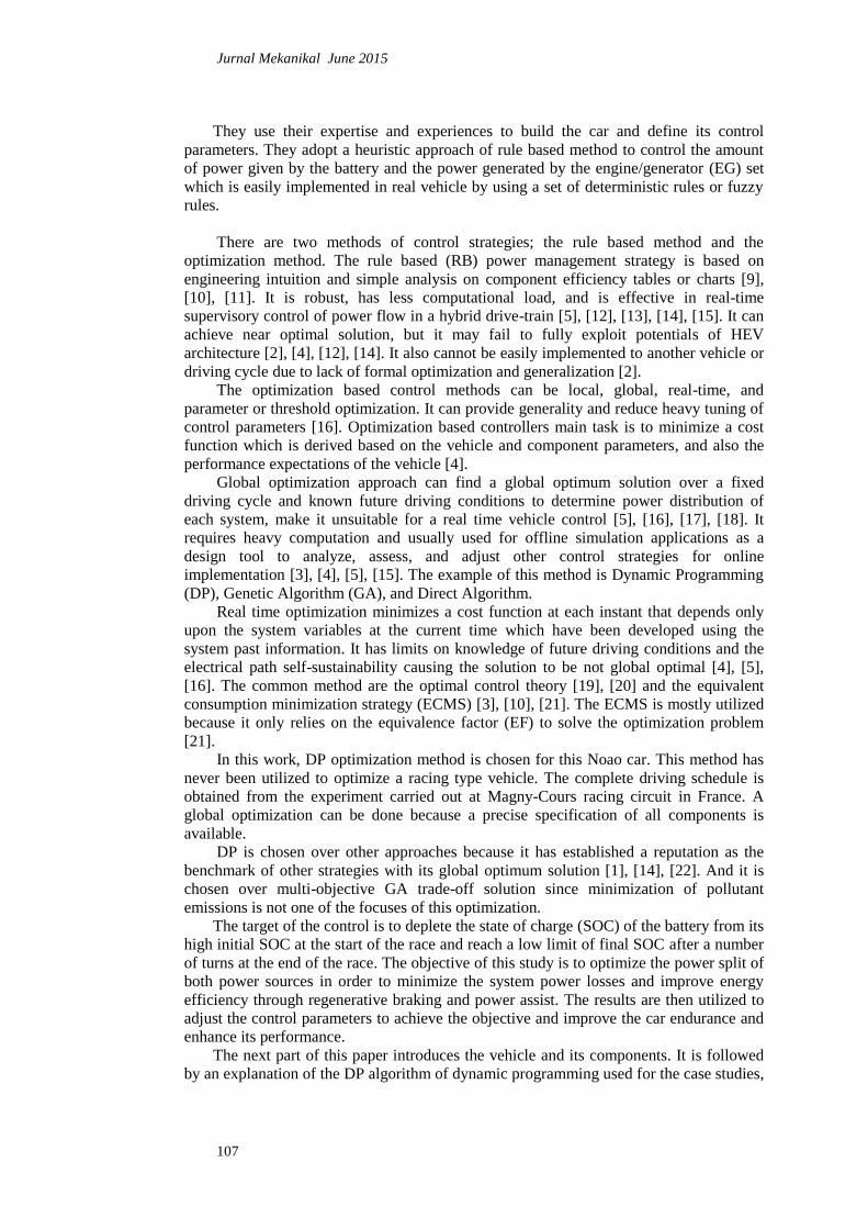
Figure 2 presents the architecture of the system which consists of transmission (T),
electric motor (EM), power conditioner (PC), lithium-ion battery (B), internal combustion
engine (ICE), and electric generator (G). Note that the arrows show the energy flows
between components in the power-train. Parameters of this vehicle are given in Table 1,
other characteristics of this vehicle can be found in the website of the association PPNMC
[7].
Figure 2: Series HEV configuration.
Table 1 : Vehicle parameters.
Mass
mv
[kg]
Front Surface
S [m2]
Drag coefficient
Cx [-]
Rolling
resistance
μ [-]
Wheel diameter
dw [m]
1200 2.0 0.35 0.012 0.62
Jurnal Mekanikal June 2015
109
2.1 Vehicle Dynamics
The power needed at wheels from the two main energy sources, the battery and the
engine are calculated using Eq. 1, referring to Guzella et al. [23].
The terms on the right side of the vehicle dynamics equation represent the sum of
aerodynamic force, friction force, inertia force, and climbing force times the average
velocity, of the car. Due to relatively high value of , the road slope factor cannot be
ignored for this racing car system. The detail of the circuit and the profile of the road
elevation in function of distance can be found in [8]. For simulation purpose, the model is
represented in a time discrete model in Matlab.
(1)
Equivalent mass is the sum of vehicle mass and the equivalent mass of the
rotating parts . It is used to calculate the inertia force to accelerate the rotating parts
inside the vehicle [23]. Different from a conventional vehicle, this mass is determined
from the EM down to the wheels as detailed in Eq. 2. From calculation, it is found out to
be 185 kg for a mechanical efficiency of 0.95, transmission ratio of 2.9, and polar
moment of inertia of 3.2 kgm2, 0.05 kgm
2, and 1.8 kgm
2 for the wheels, propeller shaft,
and electric motor respectively.
(2)
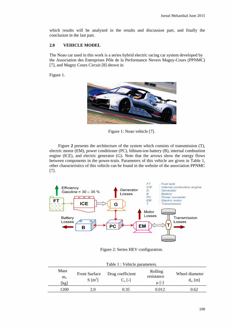
The model development of the components used in this study is based on models
developed [1], [23], [24], [25], [26], [27]. The driving cycle of the circuit and the
requested power profile at wheels are shown in Figure 3 which represent four turns of the
racing circuit. Verification of the model is made in the same figure and errors are
identified to be ±1.5%. Consistent behaviour can be observed even if there are still errors
in the power request profile of the model.
Figure 3: Driving cycle and power request profile.
2.2 Battery Model
Jurnal Mekanikal June 2015
110
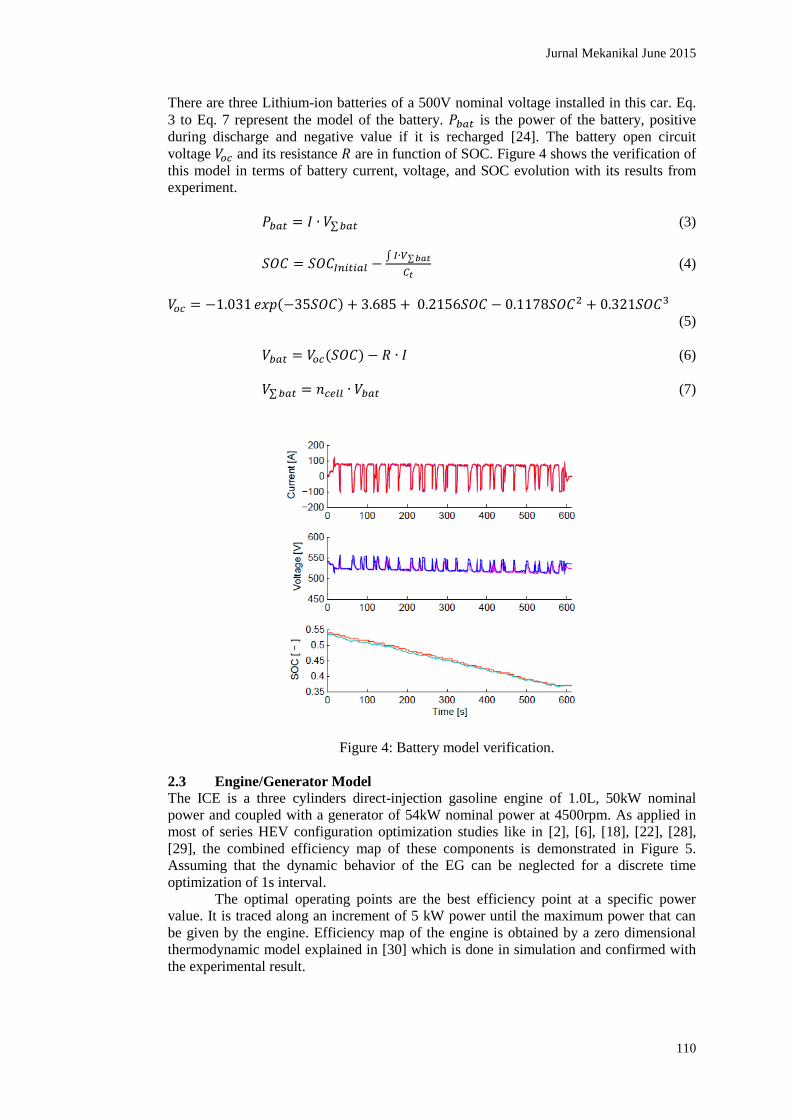
There are three Lithium-ion batteries of a 500V nominal voltage installed in this car. Eq.
3 to Eq. 7 represent the model of the battery. is the power of the battery, positive
during discharge and negative value if it is recharged [24]. The battery open circuit
voltage and its resistance are in function of SOC. Figure 4 shows the verification of
this model in terms of battery current, voltage, and SOC evolution with its results from
experiment.
(3)
(4)
(5)
(6)
(7)
Figure 4: Battery model verification.
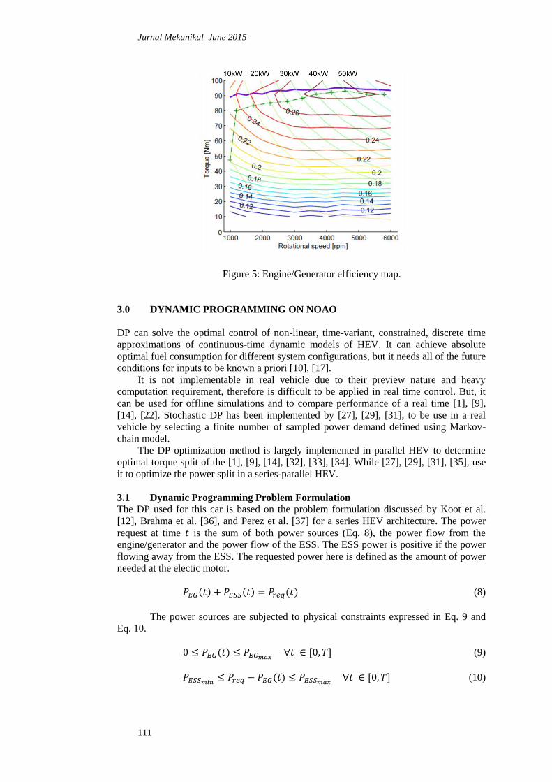
2.3 Engine/Generator Model
The ICE is a three cylinders direct-injection gasoline engine of 1.0L, 50kW nominal
power and coupled with a generator of 54kW nominal power at 4500rpm. As applied in
most of series HEV configuration optimization studies like in [2], [6], [18], [22], [28],
[29], the combined efficiency map of these components is demonstrated in Figure 5.
Assuming that the dynamic behavior of the EG can be neglected for a discrete time
optimization of 1s interval.
The optimal operating points are the best efficiency point at a specific power
value. It is traced along an increment of 5 kW power until the maximum power that can
be given by the engine. Efficiency map of the engine is obtained by a zero dimensional
thermodynamic model explained in [30] which is done in simulation and confirmed with
the experimental result.
Jurnal Mekanikal June 2015
111
Figure 5: Engine/Generator efficiency map.
3.0 DYNAMIC PROGRAMMING ON NOAO
DP can solve the optimal control of non-linear, time-variant, constrained, discrete time
approximations of continuous-time dynamic models of HEV. It can achieve absolute
optimal fuel consumption for different system configurations, but it needs all of the future
conditions for inputs to be known a priori [10], [17].
It is not implementable in real vehicle due to their preview nature and heavy
computation requirement, therefore is difficult to be applied in real time control. But, it
can be used for offline simulations and to compare performance of a real time [1], [9],
[14], [22]. Stochastic DP has been implemented by [27], [29], [31], to be use in a real
vehicle by selecting a finite number of sampled power demand defined using Markov-
chain model.
The DP optimization method is largely implemented in parallel HEV to determine
optimal torque split of the [1], [9], [14], [32], [33], [34]. While [27], [29], [31], [35], use
it to optimize the power split in a series-parallel HEV.
3.1 Dynamic Programming Problem Formulation
The DP used for this car is based on the problem formulation discussed by Koot et al.
[12], Brahma et al. [36], and Perez et al. [37] for a series HEV architecture. The power
request at time is the sum of both power sources (Eq. 8), the power flow from the
engine/generator and the power flow of the ESS. The ESS power is positive if the power
flowing away from the ESS. The requested power here is defined as the amount of power
needed at the electic motor.
(8)
The power sources are subjected to physical constraints expressed in Eq. 9 and
Eq. 10.
(9)
(10)
Jurnal Mekanikal June 2015
112
The control objective is to minimise the energy consumption of the system in a
time interval [0,T]. It finds the power flow profile in the EG path and ESS path that
minimises cost function in Eq. 11. is the amount of power of the fuel burnt.
(11)
The dynamic programming model is implemented in Matlab function developed by
[11] and is modified to improve the power split factor, applied for this system.
Battery SOC, is the state variable at instance , forms the time-variant model (Eq.
12) that includes the known variables of the driving cycle. is the number of the time
steps , which defines , the length of the problem.
(12)
(13)
(14)
Throughout this paper, the initial and final state variables and will be
changed according to optimizations carry out for this car.
3.2 Refinement of the Actual System
The rule based control strategy method implemented in the actual car decides the amount
of power that will be delivered by the battery and generated by the EG set to assist the
propulsion during traction. And help recharging the battery during regenerative braking as
can be observed in Figure 7. For this experiment, the SOC decreases from 0.54 to 0.37
after four turns of the circuit for the duration of 610 seconds. It chooses the operational
points in function of the requested power to operate the EG around its optimal operating
region.
DP optimization is carried out for the same driving cycle to see improvement that
can be made on the system energy efficiency. It is because, it is possible for the EG to
help recharging the battery or to be idle during regenerative braking phase. The compared
values are presented in Table 2.
3.3 Improvement on Vehicle Endurance
As stated before, the battery charge is expected to decrease to its lower limit by the end of
a target number of turns. And the existed defined control parameters can achieve 14 turns
of the circuit with SOC depletion from 0.9 to 0.3, assuming that the depletion is constant
between this ranges.
The endurance of the car depends on the distance it can cover before the SOC
falls to 0.3. Considering the same assumption, the car is imposed to complete 20 turns in
this DP optimization to see its feasibility for a longer autonomy range. So, using the same
driving cycle the state constraint which is the final SOC value is changed to 0.42.
Jurnal Mekanikal June 2015
113
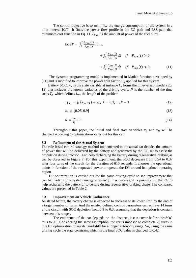
Table 2: Results comparison of DP optimization.
Actual RB
Method
DP DP Endurance
SOC Initial 0.54
SOC Final 0.37 0.37 0.42
Σ Preq [MWs] 32.448
Σ PEG [MWs] 20.894 20.513 22.790
Σ Pfuel [MWs] 84.194 76.099 84.166
Average ηEG 0.2482 0.2696 0.2708
Σ mfuel [kg] 1.914 1.729 1.913
Σ PESS [MWs] 11.554 11.935 9.6577
Σ Pbat [MWs] 11.599 11.769 9.6439
Average ηESS 0.9961 1.0141 1.0014
Average ηsystem 0.3387 0.3693 0.3459
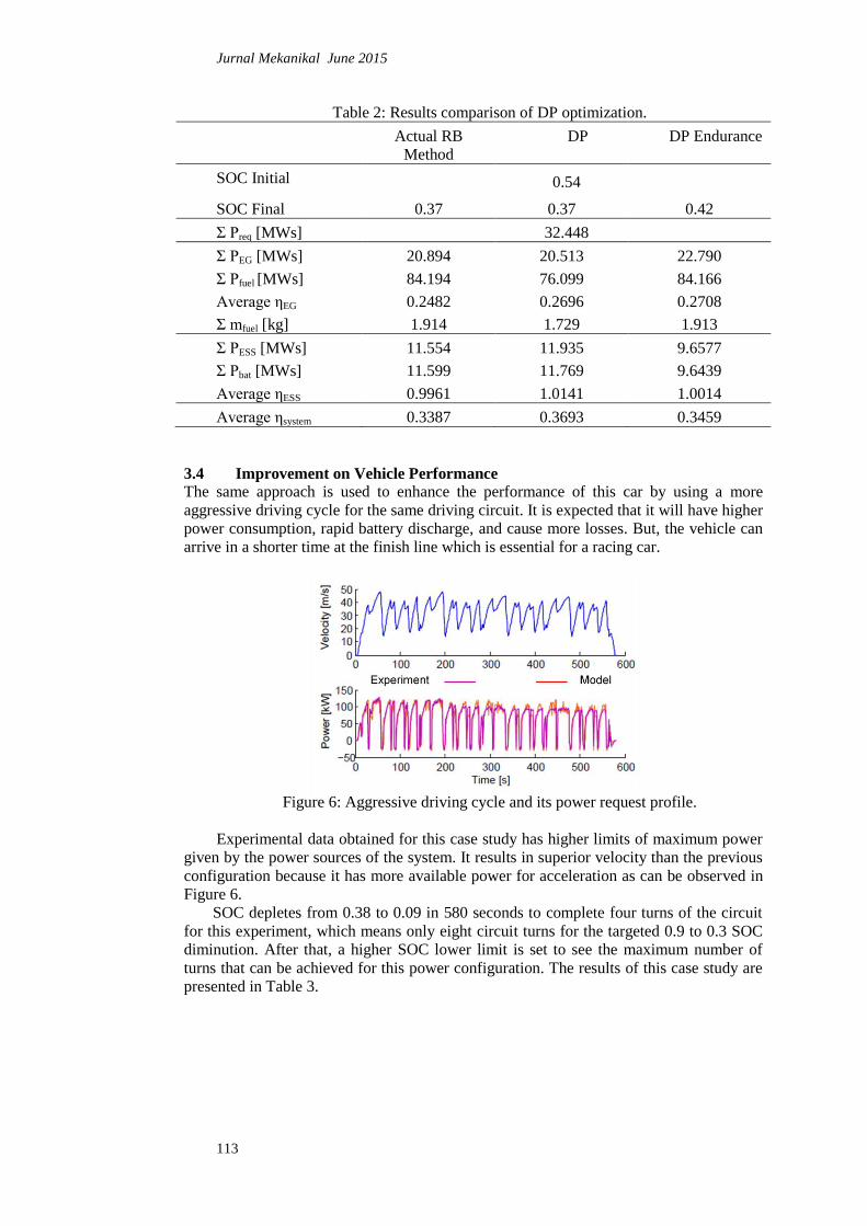
3.4 Improvement on Vehicle Performance
The same approach is used to enhance the performance of this car by using a more
aggressive driving cycle for the same driving circuit. It is expected that it will have higher
power consumption, rapid battery discharge, and cause more losses. But, the vehicle can
arrive in a shorter time at the finish line which is essential for a racing car.
Figure 6: Aggressive driving cycle and its power request profile.
Experimental data obtained for this case study has higher limits of maximum power
given by the power sources of the system. It results in superior velocity than the previous
configuration because it has more available power for acceleration as can be observed in
Figure 6.
SOC depletes from 0.38 to 0.09 in 580 seconds to complete four turns of the circuit
for this experiment, which means only eight circuit turns for the targeted 0.9 to 0.3 SOC
diminution. After that, a higher SOC lower limit is set to see the maximum number of
turns that can be achieved for this power configuration. The results of this case study are
presented in Table 3.
Jurnal Mekanikal June 2015
114
Table 3: DP optimization for better performance.
Actual RB Method DP Performance
Optimized Maximum
SOC Initial 0.38
SOC Final 0.09 0.09 0.14
Σ Preq [MWs] 38.342
Σ PEG [MWs] 19.276 17.829 21.498
Σ Pfuel [MWs] 72.600 66.483 79.377
Average ηEG 0.2655 0.2682 0.2708
Σ mfuel [kg] 1.650 1.511 1.804
Σ PESS [MWs] 19.136 20.514 16.845
Σ Pbat [MWs] 19.063 19.354 16.073
Average ηESS 0.9962 1.0600 1.0480
Average ηsystem 0.4183 0.4467 0.4017
4.0 RESULTS AND DISCUSSION
In the previous section, three study cases are highlighted in order to optimize the racing
car system. As can be seen in Table 2 and Table 3, DP approach enables the system to
have lower fuel consumption and better system efficiency compared to its actual utilized
control parameters.
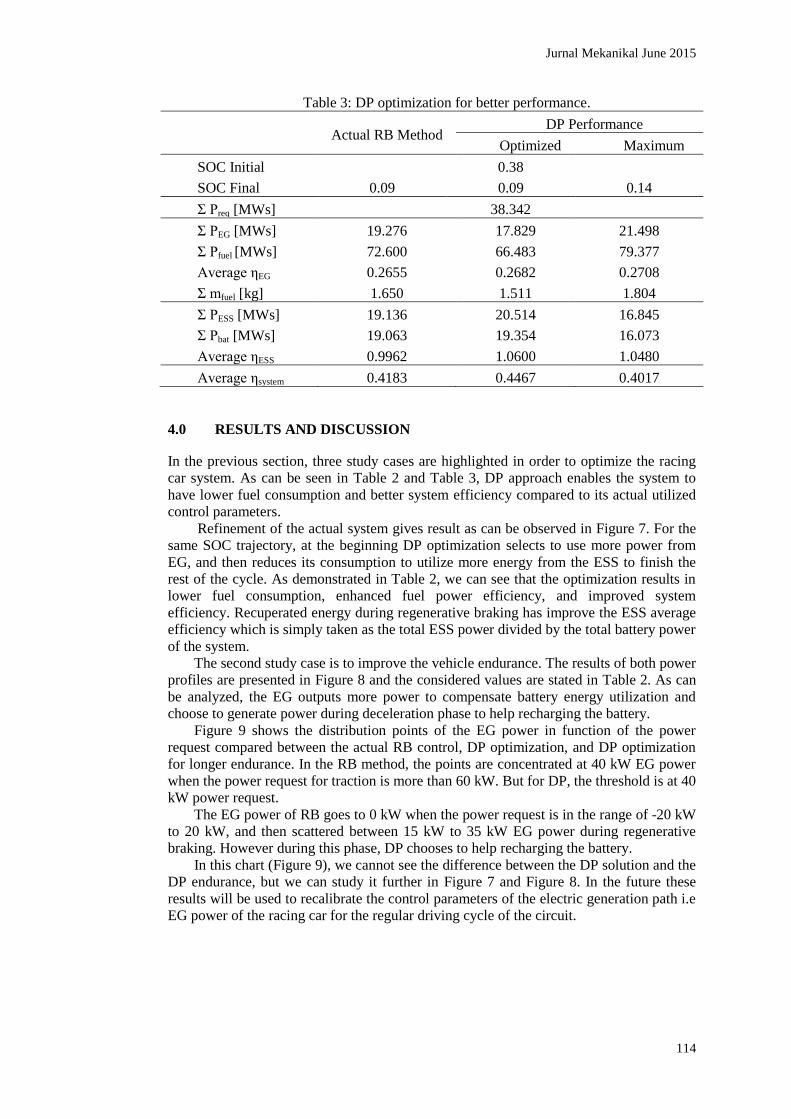
Refinement of the actual system gives result as can be observed in Figure 7. For the
same SOC trajectory, at the beginning DP optimization selects to use more power from
EG, and then reduces its consumption to utilize more energy from the ESS to finish the
rest of the cycle. As demonstrated in Table 2, we can see that the optimization results in
lower fuel consumption, enhanced fuel power efficiency, and improved system
efficiency. Recuperated energy during regenerative braking has improve the ESS average
efficiency which is simply taken as the total ESS power divided by the total battery power
of the system.
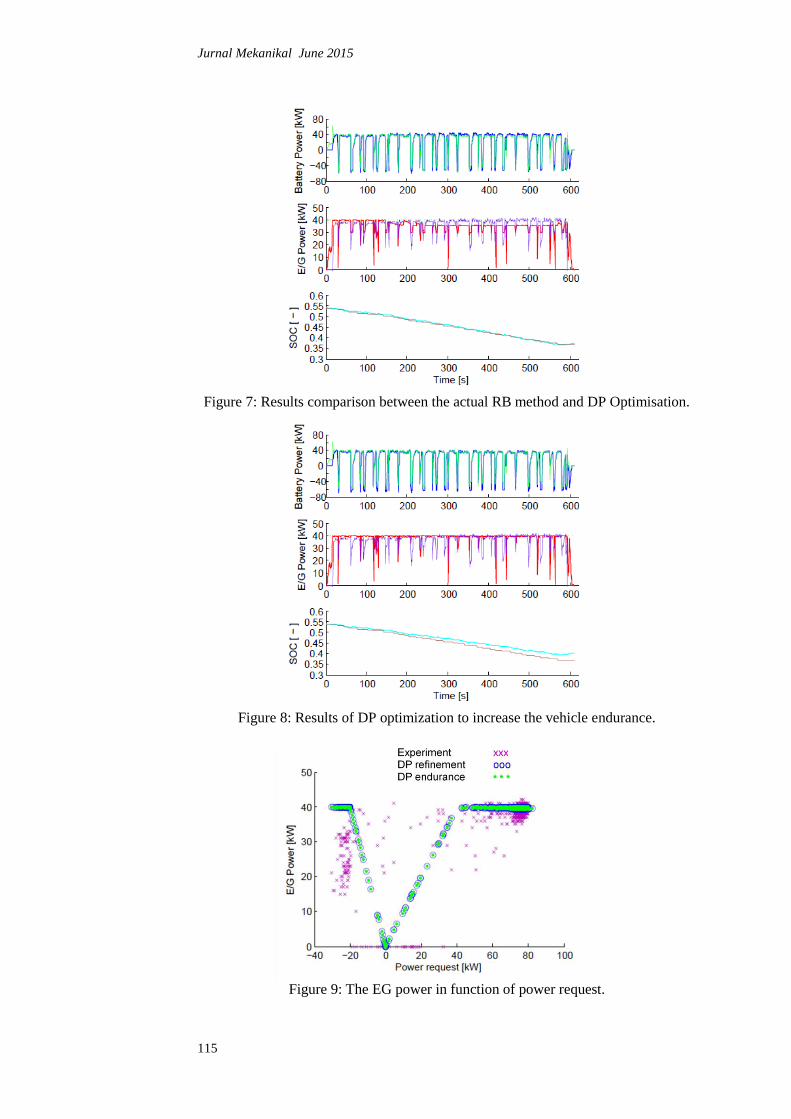
The second study case is to improve the vehicle endurance. The results of both power
profiles are presented in Figure 8 and the considered values are stated in Table 2. As can
be analyzed, the EG outputs more power to compensate battery energy utilization and
choose to generate power during deceleration phase to help recharging the battery.
Figure 9 shows the distribution points of the EG power in function of the power
request compared between the actual RB control, DP optimization, and DP optimization
for longer endurance. In the RB method, the points are concentrated at 40 kW EG power
when the power request for traction is more than 60 kW. But for DP, the threshold is at 40
kW power request.
The EG power of RB goes to 0 kW when the power request is in the range of -20 kW
to 20 kW, and then scattered between 15 kW to 35 kW EG power during regenerative
braking. However during this phase, DP chooses to help recharging the battery.
In this chart (Figure 9), we cannot see the difference between the DP solution and the
DP endurance, but we can study it further in Figure 7 and Figure 8. In the future these
results will be used to recalibrate the control parameters of the electric generation path i.e
EG power of the racing car for the regular driving cycle of the circuit.
Jurnal Mekanikal June 2015
115
Figure 7: Results comparison between the actual RB method and DP Optimisation.
Figure 8: Results of DP optimization to increase the vehicle endurance.
Figure 9: The EG power in function of power request.
Jurnal Mekanikal June 2015
116
As shown in Table 3, as expected in the last case study, the total power request is
higher for this aggressive driving cycle than in its regular driving cycle. The car can
arrive about 7.5 seconds earlier per turn but it decreases the battery charge rapidly and
causes important energy losses in the power train. In the real car, the system prefers to
utilize energy from the battery to achieve a better performance.
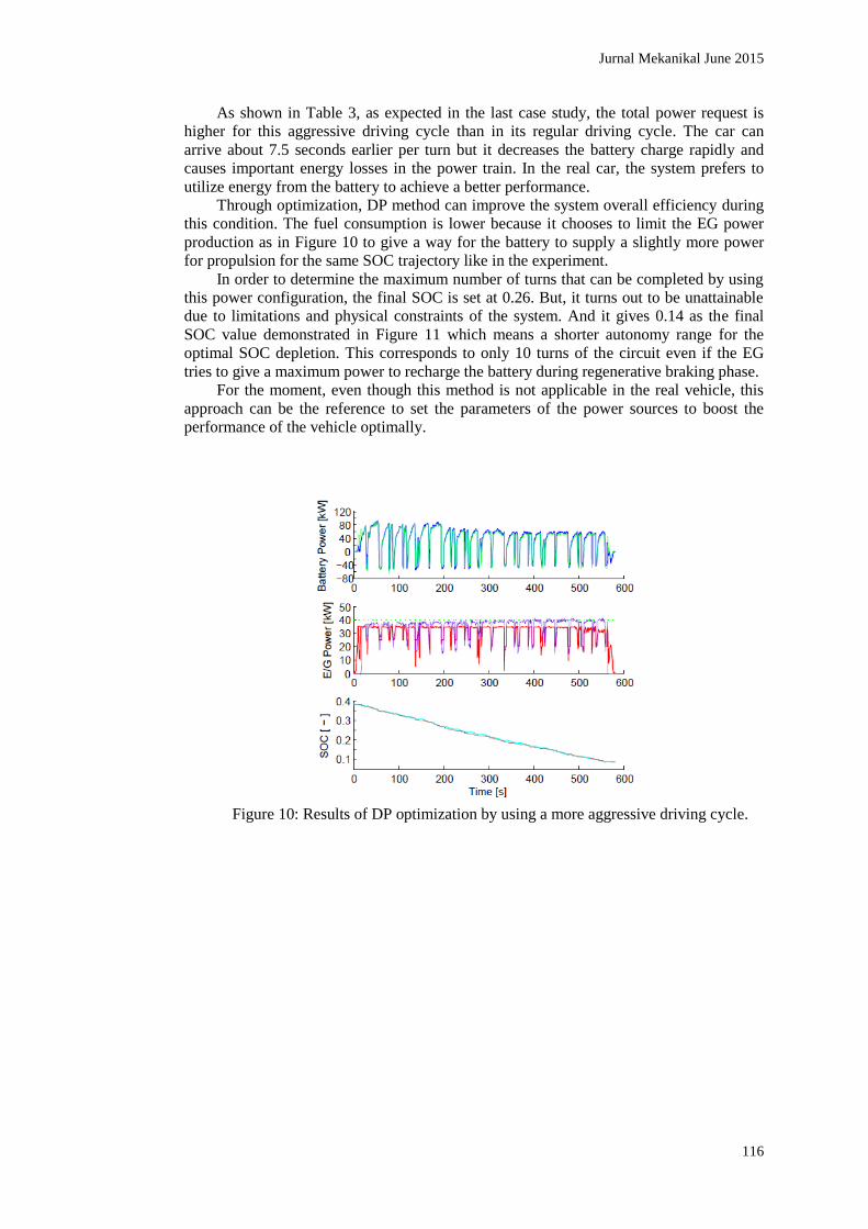
Through optimization, DP method can improve the system overall efficiency during
this condition. The fuel consumption is lower because it chooses to limit the EG power
production as in Figure 10 to give a way for the battery to supply a slightly more power
for propulsion for the same SOC trajectory like in the experiment.
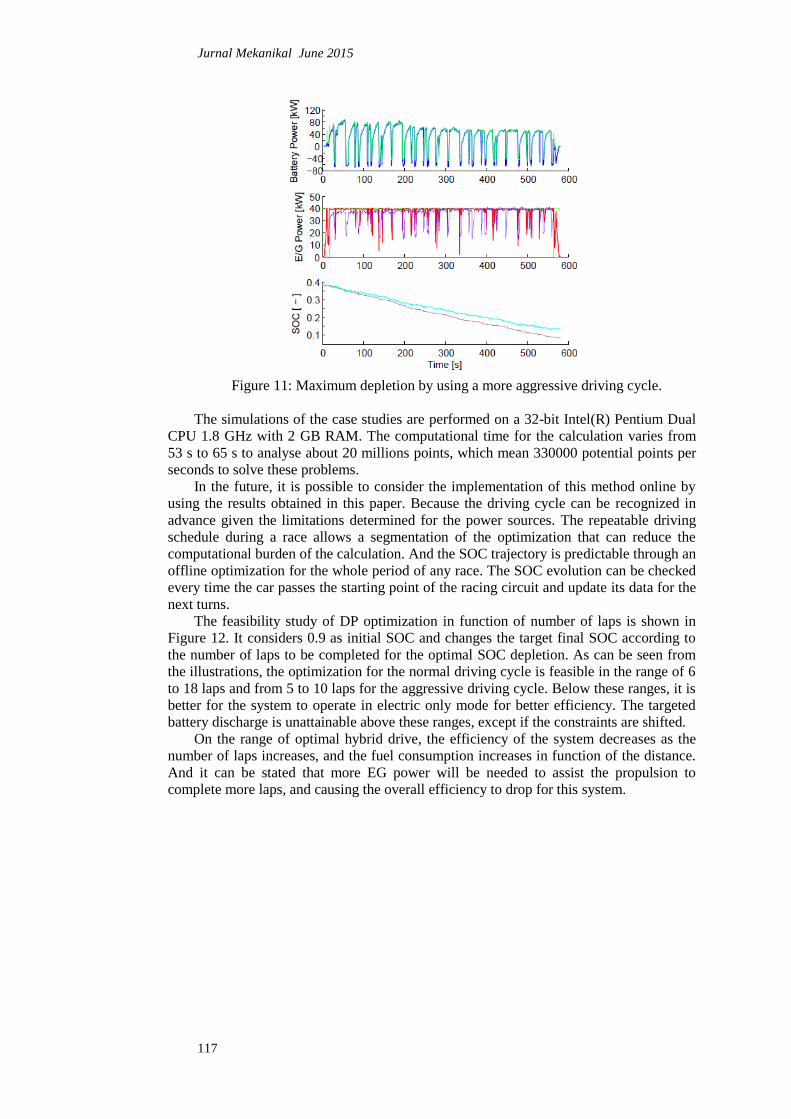
In order to determine the maximum number of turns that can be completed by using
this power configuration, the final SOC is set at 0.26. But, it turns out to be unattainable
due to limitations and physical constraints of the system. And it gives 0.14 as the final
SOC value demonstrated in Figure 11 which means a shorter autonomy range for the
optimal SOC depletion. This corresponds to only 10 turns of the circuit even if the EG
tries to give a maximum power to recharge the battery during regenerative braking phase.
For the moment, even though this method is not applicable in the real vehicle, this
approach can be the reference to set the parameters of the power sources to boost the
performance of the vehicle optimally.
Figure 10: Results of DP optimization by using a more aggressive driving cycle.
Jurnal Mekanikal June 2015
117
Figure 11: Maximum depletion by using a more aggressive driving cycle.
The simulations of the case studies are performed on a 32-bit Intel(R) Pentium Dual
CPU 1.8 GHz with 2 GB RAM. The computational time for the calculation varies from
53 s to 65 s to analyse about 20 millions points, which mean 330000 potential points per
seconds to solve these problems.
In the future, it is possible to consider the implementation of this method online by
using the results obtained in this paper. Because the driving cycle can be recognized in
advance given the limitations determined for the power sources. The repeatable driving
schedule during a race allows a segmentation of the optimization that can reduce the
computational burden of the calculation. And the SOC trajectory is predictable through an
offline optimization for the whole period of any race. The SOC evolution can be checked
every time the car passes the starting point of the racing circuit and update its data for the
next turns.
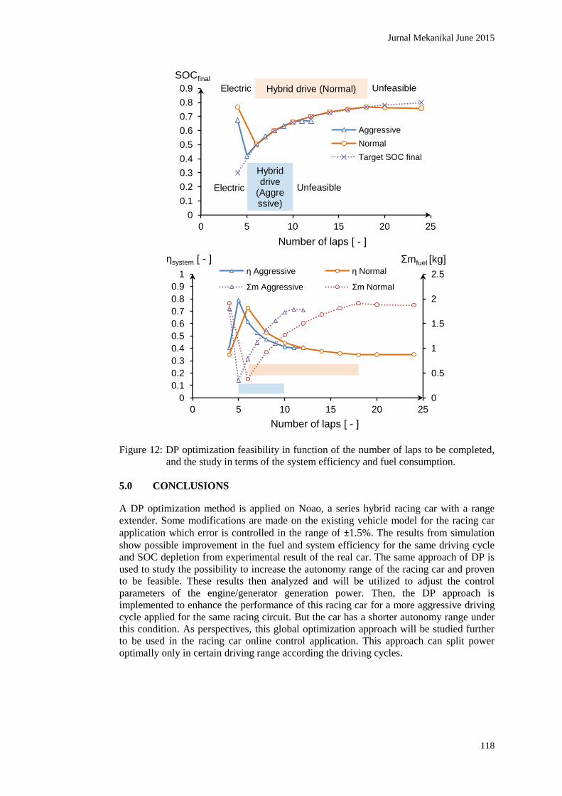
The feasibility study of DP optimization in function of number of laps is shown in
Figure 12. It considers 0.9 as initial SOC and changes the target final SOC according to
the number of laps to be completed for the optimal SOC depletion. As can be seen from
the illustrations, the optimization for the normal driving cycle is feasible in the range of 6
to 18 laps and from 5 to 10 laps for the aggressive driving cycle. Below these ranges, it is
better for the system to operate in electric only mode for better efficiency. The targeted
battery discharge is unattainable above these ranges, except if the constraints are shifted.
On the range of optimal hybrid drive, the efficiency of the system decreases as the
number of laps increases, and the fuel consumption increases in function of the distance.
And it can be stated that more EG power will be needed to assist the propulsion to
complete more laps, and causing the overall efficiency to drop for this system.
Jurnal Mekanikal June 2015
118
Figure 12: DP optimization feasibility in function of the number of laps to be completed,
and the study in terms of the system efficiency and fuel consumption.
5.0 CONCLUSIONS
A DP optimization method is applied on Noao, a series hybrid racing car with a range
extender. Some modifications are made on the existing vehicle model for the racing car
application which error is controlled in the range of ±1.5%. The results from simulation
show possible improvement in the fuel and system efficiency for the same driving cycle
and SOC depletion from experimental result of the real car. The same approach of DP is
used to study the possibility to increase the autonomy range of the racing car and proven
to be feasible. These results then analyzed and will be utilized to adjust the control
parameters of the engine/generator generation power. Then, the DP approach is
implemented to enhance the performance of this racing car for a more aggressive driving
cycle applied for the same racing circuit. But the car has a shorter autonomy range under
this condition. As perspectives, this global optimization approach will be studied further
to be used in the racing car online control application. This approach can split power
optimally only in certain driving range according the driving cycles.
0
0.1
0.2
0.3
0.4
0.5
0.6
0.7
0.8
0.9
0 5 10 15 20 25
SOCfinal
Number of laps [ - ]
Aggressive
Normal
Target SOC final
Hybrid drive (Normal)
Unfeasible Electric
Unfeasible Electric
Hybrid drive
(Aggressive)
0
0.5
1
1.5
2
2.5
0
0.1
0.2
0.3
0.4
0.5
0.6
0.7
0.8
0.9
1
0 5 10 15 20 25
Σmfuel [kg] ηsystem [ - ]
Number of laps [ - ]
η Aggressive η Normal
Σm Aggressive Σm Normal
Jurnal Mekanikal June 2015
119
ACKNOWLEDGEMENTS
Authors wish to thank Burgundy region council (CRB), Malaysian Government and
UTM (University of Technology Malaysia) for continuous support.
REFERENCES
[1] C.C. Lin, et al., Integrated, Feed-Forward Hybrid Electric Vehicle Simulation in
SIMULINK and its Use for Power Management Studies, SAE Paper no. 2001-01-
1334 (2001).
[2] L. Serrao, S. Onori, and G. Rizzoni, A Comparative Analysis of Energy
Management Strategies for Hybrid Electric Vehicles, Journal of Dynamic Systems,
Measurement, and Control 133 (3) (2011).
[3] J.P. Gao, G.M.G. Zhu, E.G. Strangas, and F.C. Sun, Equivalent fuel consumption
optimal control of a series hybrid electric vehicle, Journal of Automobile Engineering 8
(223) (2009) 1003-1018.
[4] S.G. Wirasingha and A. Emadi, Classification and Review of Control Strategies for
Plug-In Hybrid Electric Vehicles, IEEE Transactions on Vehicular Technology
60(1) (2011) 111-122.
[5] F.R. Salmasi, Control Strategies for Hybrid Electric Vehicles: Evolution,
Classification, Comparison, and Future Trends, IEEE Transactions on Vehicular
Technology 56(5) (2007) 2393-2404.
[6] J. Park, Y. Park, and J.H. Park, Real-Time Powertrain Control Strategy for Series-
Parallel Hybrid Electric Vehicles, SAE Technical Paper Series no. 2007-01-3472
(2007) 1-9.
[7] Pôle de la performance de Nevers Magny-Cours. Noao, vehicule electrique avec
prolongateur d'autonomie. Pole de la performance de Nevers Magny-Cours.
Available from: http://www.asso-ppnmc.fr [accessed 15 March 2013]
[8] Magny-Cours International Circuit. Pistes et pilotage, Presentation de la Piste
Grand Prix. Available from: http://www.circuitmagnycours.com [accessed 5
February 2013]
[9] C.C. Lin, H. Peng, J.W. Grizzle, and J.M. Kang, Power Management Strategy for a
Parallel Hybrid Electric Truck, IEEE Transactions on Control Systems Technology
11(6) (2003) 839-850.
[10] D. Ambühl and L. Guzzella, Predictive Reference Signal Generator for Hybrid
Electric Vehicles, IEEE Transactions on Vehicular Technology 58(9) (2009) 4730-
4740.
[11] O. Sundstrom and L. Guzzella, A Generic Dynamic Programming Matlab Function,
in 18th IEEE International Conference on Control Applications, Saint Petersburg,
Russia, Jul. 2009, pp. 1625-1630.
[12] M. Koot, et al., Energy Management Strategies for Vehicular Electric Power
Systems, IEEE Transactions on Vehicular Technology 54(3) (2005) 771-782.
[13] R. Langari and J.S. Won, Intelligent Energy Management Agent for a Parallel
Hybrid Vehicle-Part I: System Architecture and Design of the Driving Situation
Identification Process, IEEE Transactions on Vehicular Technology 54(3) (2005)
925-934.
[14] Q. Gong, Y. Li, and Z.R. Peng, Trip Based Optimal Power Management of Plug-in
Hybrid Electric Vehicles Using Gas-Kinetic Traffic Flow Model, IEEE
Transactions on Vehicular Technology 57(6) (2008) 3393-3401.
Jurnal Mekanikal June 2015
120
[15] K.C. Bayindir, M.A. Gozukucuk, and A. Teke, A comprehensive overview of
hybrid electric vehicle: Powertrain configurations, powertrain control techniques
and electronic control units, Energy Conversion and Management 52(2) (2011)
1305-1313.
[16] A. Sciarretta, M. Back, and L. Guzzella, Optimal Control of Parallel Hybrid
Electric Vehicles, IEEE Transactions on Control Systems Technology 12(3) (2004)
352-363.
[17] O. Sundstrom, L. Guzzella, and P. Soltic, Optimal Hybridization in Two Parallel
Hybrid Electric Vehicles using Dynamic Programming, in The International
Federation of Automatic Control, Jul. 2008.
[18] C.E. Nino-Baron, A.R. Tariq, G. Zhu, and E.G. Strangas, Trajectory Optimization
for the Engine-Generator Operation of a Series Hybrid Electric Vehicle, IEEE
Transactions on Vehicular Technology 60(6) (2011) 2438-2447.
[19] S. Delprat, J. Lauber, T.M. Guerra, and J. Rimaux, Control of a Parallel Hybrid
Powertrain: Optimal Control, IEEE Transactions on Vehicular Technology 53(3)
(2004) 872-881.
[20] D.V. Ngo, T. Hofman, M. Steinbuch, and A.F.A. Serrarens, An Optimal Control-
Based Algorithm for Hybrid Electric Vehicle using Preview Route Information, in
American Control Conference, Baltimore, USA, June 2010, pp. 5818-5823.
[21] B. Geng, J.K. Mills, and D. Sun, Energy Management Control of Microturbine
Powered Plug-In Hybrid Electric Vehicles Using Telemetry Equivalent
Consumption Minimization Strategy, IEEE Transactions on Vehicular Technology
60(9) (2011) 4238-4248.
[22] V. Sezer, M. Gokasan, and S. Bogosyan, A Novel ECMS and Combined Cost Map
Approach for High-Efficiency Series Hybrid Electric Vehicles, IEEE Transactions
on Vehicular Technology 60(8) (2011) 3557-3570.
[23] L. Guzella and A. Sciarretta, Vehicle Propulsion Systems, second ed., Springer,
Zurich, Switzerland, 2007.
[24] K.L. Butler, M. Ehsani, and P. Kamath, A Matlab-Based Modeling and Simulation
Package for Electric and Hybrid Electric Vehicle Design, IEEE Transactions on
Vehicular Technology 48(6) (1999) 1770-1778.
[25] G. Rizzoni, L. Guzzella, and B.M. Baumann, Unified Modeling of Hybrid Electric
Vehicle Drivetrains, IEEE/ASME Transactions on Mechatronics 4(3) (1999) 246-
257.
[26] M. Ehsani, Y. Gao, S.E. Gay, and A. Emadi, Modern Electric, Hybrid Electric, and
Fuel Cell Vehicles: Fundamentals, Theory, and Design. CRC Press, Texas, US,
2004.
[27] J. Liu and H. Peng, Modeling and Control of a Power-Split Hybrid Vehicle, IEEE
Transactions on Control Systems Technology 16(6) (2008) 1242-1251.
[28] A. Konev and L. Lezhnev, Control Strategy Optimization for a Series Hybrid
Vehicle, SAE Technical Paper Series no. 2006-01-0663 (2006).
[29] S.J. Moura, H.K. Fathy, D.S. Callaway, and J.L. Stein, A Stochastic Optimal
Control Approach for Power Management in Plug-In Hybrid Electric Vehicles,
IEEE Transactions on Control Systems Technology 19(3) (2011) 545-555.
[30] Z. Asus, D. Chrenko, E.H. Aglzim, A. Keromnes, and L. Le-Moyne, Simple
method of estimating consumption of internal combustion engine for hybrid
application, in IEEE Transportation Electrification Conference and Expo (iTEC),
Michigan, USA, June 2012.
Jurnal Mekanikal June 2015
121
[31] D.F. Opila, et al., An Energy Management Controller to Optimally Trade Off Fuel
Economy and Drivability for Hybrid Vehicles, IEEE Transactions on Control
Systems Technology 99 (2011) 1-16.
[32] Q. Gong, Y. Li, and Z.R. Peng, Trip Based Power Management of Plug-in Hybrid
Electric Vehicle with Two-Scale Dynamic Programming, in IEEE Vehicle Power
and Propulsion Conference, Sep. 2007, pp. 12-19.
[33] Q. Gong, Y. Li, and Z. Peng, Power Management of Plug-in Hybrid Electric
Vehicles Using Neural Network Based Trip Modeling, in American Control
Conference, Jun. 2009, pp. 4601-4606.
[34] C.C. Lin, H. Peng, and J.W. Grizzle, A Stochastic Control Strategy for Hybrid
Electric Vehicles, in American Control Conference, vol. 5, Jul. 2004, pp. 4710-
4715.
[35] J.F. Bonnans, et al., Parametric Optimization of Hybrid Car Engines, Optimisation
and Engineering 5(4) (2004) 395-415.
[36] A. Brahma, Y. Guezennec, and G. Rizzoni, Optimal Energy Management in Series
Hybrid Electric Vehicles, in American Control Conference, vol. 1, Sep. 2000, pp.
60-64.
[37] L.V. Perez, G.R. Bossio, D. Moitre, and G.O. Garcia, Optimization of power
management in an hybrid electric vehicle using dynamic programming,
Mathematics and Computers in Simulation 73 (2006) 244–254.
[38] A. Sciarretta and L. Guzzella, Control of Hybrid Electric Vehicles: Optimal Energy
Management Strategies, IEEE Control Systems Magazine 27(2) (2007) 60-70.
[39] L. Guzzella and C.H. Onder, Introduction to Modeling and Control of Internal
Combustion Engine Systems, second ed., Springer, Zurich, Switzerland, 2009.