Embed Size (px)
Citation preview

Chen 1
OPTIMIZATION OF FRONT END STRUCTURES FOR IIHS SMALL OVERLAP FRONTAL CRASH TEST Guofei Chen and Ming F. Shi United States Steel Corporation USA Tau Tyan Ford Motor Company USA Paper Number 19-0188
ABSTRACT The Insurance Institute for Highway Safety (IIHS) introduced a small overlap rigid barrier (SORB) crash test in 2012. In the IIHS SORB tests, the rigid barrier primarily impacts a vehicle's outer edges instead of the main longitudinal structures traditionally designed to absorb frontal impact energy. Due to the test condition, the front wheels are often forced to move rearward and into the footwell, contributing to significant and localized intrusion in the occupant compartment. To investigate the design countermeasures for such a severe test mode, the full vehicle model developed in the final phase of the Future Steel Vehicle (FSV) program by WorldAutoSteel was adopted as a baseline. In this study, innovative countermeasure design concepts for the front end structures, especially bumper beam, shotgun, front rail, A-pillar, hinge pillar, and rocker, were proposed and optimized with the FSV full vehicle model. The optimized designs helped the vehicle slide away from the small overlap rigid barrier and converted more impact energy to vehicle kinetic energy. When used together with ultra high strength steel (UHSS), the intrusion into the occupant compartment was reduced and the overall structural rating was improved from “Marginal” to “Good” in the SORB test. In the meantime, the design concepts reduced intrusion in the IIHS 40% overlap deformable barrier (ODB) test and maintained a similar crash pulse in the US-NCAP full frontal crash test. The potential mass reduction opportunity with the design concepts and UHSS was also evaluated. INTRODUCTION Over the last several decades, tremendous progress in vehicle frontal crash performance has been achieved. The automotive community has made considerable efforts in developing optimized crumple zone structures with higher strength materials such as advanced high strength steels (AHSS) to absorb the crash energy. In 2012, the IIHS released the more demanding frontal offset test named the small overlap rigid barrier (SORB) crash test [1, 2]. The new test, which is used in addition to the 40% overlap deformable barrier (ODB) test introduced in 1995, subjects only 25% of the front end of the vehicle to a 64.4 km/hr (40 mph) impact into a 1524-mm-tall (5 feet) rigid barrier. The new test is far more demanding on the vehicle structures than the 40% ODB test. What makes the small overlap crash test so challenging is that the outer front wheel receives the impact forces first rather than the more central crash absorbing structures such as the longitudinal structural members. The crash forces are concentrated on the front suspension, the firewall, the hinge pillar and the base of the A-pillar, which are not traditionally designed to absorb and dissipate crash forces in a front impact. The vehicle performance in the IIHS small overlap frontal crash test is rated based on three categories: restraints and dummy kinematics, dummy injury measures, and vehicle structural performance [3]. Since the release of the IIHS SORB crash test protocol, the IIHS has evaluated numerous midsized and small cars, with few vehicles earning the top rating of good, particularly due to the structural performance rating. Most of the vehicles on the road in 2012 could not meet the targets for a ‘good’ rating in this test and all vehicle manufacturers started incorporating counter measures to improve SORB performance [4]. The advancement in computer optimization technologies and the availability in higher strength of AHSS in GigaPascal-strength levels provide opportunities to develop countermeasure designs to improve the overall

Chen 2
structural rating in the SORB crash test. In this study, a full vehicle finite element model was utilized in the SORB crash test simulation to identify the critical components contributing to the performance in the SORB crash event. Innovative countermeasure design concepts with ultra high strength steels (UHSS) were developed and optimized for the front end structures, especially bumper beam, shotgun, front rail, A-pillar, hinge pillar, and rocker. The potential vehicle weight reduction opportunity with the optimized design concepts and UHSS was also evaluated. SORB CRASH SIMULATION MODEL The full vehicle finite element model developed in the final phase of the Future Steel Vehicle (FSV) program [4] by WorldAutoSteel in 2011 was adopted as the baseline in this study, as shown in Figure 1. The FSV features optimized AHSS body structure designs that reduce mass by more than 35 percent over a baseline ICE body structure adjusted for a battery electric powertrain. More than 20 new AHSS grades, representing materials expected to be commercially available in the 2015 – 2020 technology horizon, are applied in the FSV final concept designs. The material portfolio includes dual phase (DP), transformation-induced plasticity (TRIP), twinning-induced plasticity (TWIP), complex phase (CP) and hot formed (HF) steels, which are the newest in steel technology offered by the global industry. The FSV uses 97 percent HSS and AHSS with nearly 50 percent of the steels at GigaPascal-strength levels. The FSV front end structures feature:
• A front rail sub-system with the optimized section shape of the rails that improved crash energy management while reducing mass. It was manufactured using a laser welded blank with varying gauges of TRIP material.
• A shotgun sub-system resembling a shotgun-type rifle that provided enhanced performance in both full frontal and offset crash simulations. The shot gun was designed with a three-piece hot formed steel tailor welded blank of varying thicknesses.
The FSV final concept designs met a broad list of global crash and durability requirements, including the US-NCAP and the IIHS 40% ODB frontal crash criteria. Since FSV was developed before the SORB crash test was introduced in 2012, the SORB crash test was not considered in the FSV program.
Figure 1. FSV full vehicle finite element model In this study, the crash simulation model for the SORB test was developed using the FSV final concept design as the baseline, as shown in Figure 2. The vehicle was aligned with a rigid barrier such that the right edge of the barrier face is offset to the left of the vehicle centerline by 25 percent of the vehicle’s width [2]. The vehicle crashed into the 1524-mm-tall (5 feet) rigid barrier at 64.4 km/hr (40 mph) speed.
Chen 3
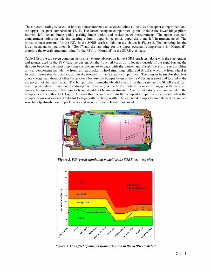
The structural rating is based on intrusion measurements on selected points at the lower occupant compartment and the upper occupant compartment [2, 3]. The lower occupant compartment points include the lower hinge pillar, footrest, left toepan, brake pedal, parking brake pedal, and rocker panel measurements. The upper occupant compartment points include the steering column, upper hinge pillar, upper dash, and left instrument panel. The intrusion measurements for the FSV in the SORB crash simulation are shown in Figure 3. The subrating for the lower occupant compartment is “Good” and the subrating for the upper occupant compartment is “Marginal”, therefore the overall structural rating for the FSV is “Marginal” in the SORB crash test. Table 1 lists the top seven components in crash energy absorption in the SORB crash test along with the steel grades and gauges used in the FSV baseline design. As the front rail crash tip is located outside of the rigid barrier, the shotgun becomes the most important component to engage with the barrier and absorb the crash energy. Other critical components include the front rail rear, rocker, wheel rim, hinge pillar and A-pillar when the front wheel is forced to move rearward and crash into the footwell of the occupant compartment. The bumper beam absorbed less crash energy than those of other components because the bumper beam in the FSV design is short and located at the arc portion of the rigid barrier. The bumper beam immediately slid away from the barrier in the SORB crash test, resulting in reduced crash energy absorption. However, as the first structural member to engage with the crash barrier, the importance of the bumper beam should not be underestimated. A sensitivity study was conducted on the bumper beam length effect. Figure 3 shows that the intrusion into the occupant compartment decreased when the bumper beam was extended outward to align with the body width. The extended bumper beam enlarged the impact zone to help absorb more impact energy and increase vehicle lateral movement.
Figure 2. FSV crash simulation model for the SORB test – top view
Figure 3. The effect of bumper beam extension in the SORB crash test

Chen 4
Table 1. Top components in SORB crash energy absorption
Part Name Material Gauge (mm) Energy Absorbed (kJ) Percentage (% )Shotgun HF1550 1.0/1.2/1.5 17.80 11.41Front Rail TRIP980 1.8/2.0/1.9/1.8 9.00 5.77
Rocker CP1470 1.0 8.85 5.67Wheel Rim HSLA350 2.0 7.56 4.85Hinge Pillar DP780 1.2 6.55 4.20
A-Pillar HF1550 0.7 5.64 3.62Bumper Beam DP780 1.0 3.46 2.22
DESIGN OPTIMIZATION FOR THE SORB In this study, the bumper beam, shotgun, front rail, A-pillar, hinge pillar, and rocker were selected in the design optimization, including geometry, gauge and steel grade optimization. Before the geometry optimization, the FSV front end structures were modified. The bumper beam was extended outward and the shotgun was extended forward into the extended bumper beam. Then, the shot gun was connected with the front face of the extended bumper beam by bolt joints or spot welds to strengthen the front end side structures so that both the shot gun and the bumper beam can engage with the barrier earlier during the initial impact. As a result, the impact loads could be distributed to the upper and lower body structures. In addition, more impact loads could be transferred to the non-impact side than a traditional design with only the front rails connected to the bumper beam. The shape variables in the geometry optimization include the extension length of the bumper beam and the transition shape of the shotgun from the body side to the bumper beam. The objective of the optimization is to improve the overall SORB structural rating to “Good” from “Marginal” in the FSV baseline design without mass penalty. In the meantime, the baseline design is optimized to maintain or enhance crash performance in the IIHS 40% ODB and US-NCAP full frontal crash tests. HyperStudy® optimization software and LS-DYNA® nonlinear finite element software were utilized together for the geometry, gauge and steel grade optimization [5, 6].
Figure 4. Connection between the shot gun and the extended bumper beam OPTIMIZED DESIGN CONCEPTS An optimized design concept for the SORB crash test is shown in Figure 5. It features:
• An extended bumper beam at both ends. The bumper beam was extended as far as possible to align with the body width. The extended bumper beam would enlarge the impact zone to help absorb more crash energy and increase vehicle lateral movement.
• A new connection between the shotgun and the front face of the extended bumper beam. The system with the bumper beam integrated both the shotgun and front rail would strengthen the front end side structures,

Chen 5
engage the shotgun with barriers earlier, distribute impact load to upper and lower body structures, and transfer more impact load to the non-impact side than traditional design with only front rails connected to the bumper beam.
• A shape optimized shotgun with a “snake-shaped” transition from the body side to the corner of the rigid barrier. The optimized shape of the shotgun would increase the vehicle lateral movement by helping the vehicle slide away from the barrier and converting the impact energy to the vehicle kinetic energy. Figure 6 shows the comparison of vehicle lateral movement of the optimized new design with the FSV baseline in the SORB crash test.
(a) Top view (b) Side view
Figure 5. An optimized design concept for the SORB crash test
Y
500
600
400
300
200
100
0
-1000.02 0.04 0.06 0.08 0.1 0.12 0.140
Y-d
isp
lace
men
t (m
m)
Time (sec)
(a) Vehicle lateral movement (b) Comparison
Figure 6. Comparison of vehicle lateral movement in the SORB test
Figures 7 and 8 show the comparison in the vehicle deformation and intrusion into the occupant compartment from the SORB test, respectively. Since the optimized new design helped the vehicle slide away from the SORB, less deformation was observed at the shotgun, hinge-pillar, rocker, roof rail and tire in the optimized new design. As a result, the intrusion into the occupant compartment was reduced, and the overall SORB structural rating was improved to “Good” from “Marginal” in the FSV baseline design. The optimized shotgun and bumper beam also helped transfer the impact force to the non-impact side and reduced deformation/intrusion on the impact side in the IIHS 40% ODB frontal crash test, as shown in Figure 9(a). The intrusion was improved further to a “Good” structural rating with a higher probability and confidence level.

Chen 6
As both the front rails and the shotgun are connected to the bumper beam, one concern is that the front-end structures may be too stiff and can deteriorate the vehicle crash performance such as the deceleration pulse in the US-NCAP frontal crash test. Figure 9(b) shows the optimized new design had similar pulse responses in the NCAP full frontal test to that of the FSV baseline design, allowing similar occupant responses. This was achieved by slightly reducing the gauges of the front rails, as shown in Table 2, to balance the stiffness of the front rails and the shotgun as both of them were connected to the bumper beam. Table 2 compares the materials, gauges and mass between the optimized new design and the FSV baseline design for some key components. More ultra high strength steels (UHSS) such as TRIP980 and HF1550 were used in the optimized new design. The total mass of the optimized new design remains similar to that of the FSV baseline with the intrusion reductions in both the IIHS SORB and the 40% ODB crash tests.
(a) FSV baseline (b) Optimized design for SORB
Figure 7. Comparison of vehicle deformation in the SORB test
Figure 8. Comparison of intrusion in the SORB test

Chen 7
Good
Acceptable
Marginal
Poor
40
30
20
10
0
-100.02 0.04 0.060
Dec
eler
atio
n (
G)
Time (sec) (a) IIHS 40% ODB (b) US-NCAP
Figure 9. Comparison of crash performance in the IIHS 40% ODB and the US-NCAP tests
Table 2. Optimized materials and gauges for key components
Part Name Material Gauge (mm) Mass (kg) Material Gauge (mm) Mass (kg)Shotgun HF1550 1.0/1.2/1.5 8.9 HF1550 1.2/1.2/1.3 8.5
Bumper Beam DP780 1.0 3.7 HF1550 0.8 3.5Rocker Reinf CP1470 1.0 11.9 CP1470 1.2/1.0 12.7Rocker Outer DP590 0.8 6.2 TRIP980 0.8 6.2
Hinge Pillar Inner DP780 1.2 3.3 HF1550 1.2 3.3Hinge Pillar Outer DP590 0.8 2.5 TRIP980 0.8 2.5
A-Pillar Inner HF1550 0.7 1.7 HF1550 0.7 1.7A-Pillar Outer DP590 0.8 5.3 TRIP980 0.8 5.3
Roof Rail Inner HF1550 0.95/0.8 2.1 HF1550 0.95/0.8 2.1Roof Rail Reinf HF1550 0.7 4.1 HF1550 0.7 4.1
Front Rail TRIP980 1.8/2.0/1.9/1.8 18.7 TRIP980 1.8/1.9/1.8/1.8 18.5Total Mass (kg) 68.4 68.4
FSV-Baseline Optimized New Design
It is noticed from Figure 7(b) that the front wheel was still forced rearward into the footwell, causing the deformation of the rocker and hinge pillar. To alleviate the impact from the front wheel, a second design concept was proposed based on the previous design concept by optimizing the directions the bumper beam to be extended. As shown in Figure 10 for optimized design concept #2, the straight outward extension in the previous design concept was modified by extending the bumper beam:
• Rearward to be as close as possible to the front edges of the front wheel; • Downward to be as close as possible to the centerline of the front wheel.
During the impact in the SORB test, the extended bumper beam is intended to move rearward to contact with the outer edges of the front wheel and subsequently to turn the front wheel outward. To turn the front wheel more effectively, the bumper beam was designed with a tailor-welded-blank (TWB) or two parts joined together with a relatively stiffer outside portion.
Figure 11(a) shows the deformation of optimized design concept #2 in the SORB test. As the intended design, the front wheel was turned outward by the bumper beam to reduce the direct impact force from the front wheel to the rocker and hinge pillar. When compared to the deformation of optimized design concept #1 shown in Figure 7(b), optimized design concept #2 had less deformation in the rocker, hinge pillar and the roof rail. Consequently, the intrusion into the occupant compartment was reduced by 2 cm, as shown in Figure 11(b). Optimized design concept #2 further improved the structural rating to “Good” for the upper occupant compartment with higher probability and confidence level, enabling mass reduction while maintaining the “Good” overall structural rating.

Chen 8
Materials and gauges for the two optimized design concepts are compared in Table 3. In optimized design concept #2, the gauges of the bumper beam were increased to 1.2 mm for its outside portions, while the front and middle portions of the TWB shotgun were downgauged to 0.6 and 0.8 mm, respectively. Because concept #2 changed the front wheel kinematics, the front portion of the TWB rocker reinforcement and the rocker outer could be downgauged by 0.1 mm. Total mass reduction of 1.3 kg was achieved with optimized design concept #2, while maintaining the “Good” overall structural rating.
THE NEXT GENERATION AHSS The current study focused on the countermeasure design optimizations using the available steels grades used in the FSV vehicle model. Since then, the next generation AHSS with an excellent combination of strength and ductility have become available and been commercialized. For example, U. S. Steel’s third generation steel with 980 MPa minimum tensile strength (980 XG3TM steel) has comparable crash performance to HF1550 with minimum weight penalty [8, 9]. It was demonstrated that same gauged 980 XG3TM steel could replace hot formed HF1550 steel for hinge pillars for a sedan with complex geometry, and achieved a “Good” rating in IIHS SORB crash test [9]. The benefits of cold-stamping versus hot-stamping include cost reduction and improved corrosion protection. Other currently available next generation AHSS are:
1. Super high formable steel with 1180 MPa minimum tensile strength (1180SHF); 2. Martensitic steel with 1500 MPa minimum tensile strength (MS1500); 3. Martensitic steel with 1700 MPa minimum tensile strength (MS1700); 4. Dual phase steel with 1470 MPa minimum tensile strength (DP1470).
Table 4 shows the potential material recommendation with the next generation AHSS, which have equivalent strength and improved ductility compared to the steel grades used in the FSV model. 980 XG3TM steel can be used to replace HF1550 and TRIP980 for the shotgun, hinge pillars, A-pillar outer, front rail and rocker outer. The HF1550 bumper beam, rocker reinforcement and roof rail can be replaced with MS1500/MS1700, DP1470 and 1180SHF, respectively. The flow stresses of the cold-stamped 980 XG3TM and 1180SHF parts can match that of the hot-stamped HF1550 parts when the work and bake hardening effects are considered. The 980 XG3TM and 1180SHF steels also demonstrate greatly improved fracture resistance performance during crash events because their fracture limit strains are significantly higher than that of HF1550 [10, 11]. It is expected to achieve similar crash performance with the next generation AHSS for the two optimized designs shown in Table 3 at similar mass savings, but reduced costs.
(a) Top view (b) Side view
Figure 10. Optimized design concept #2 for SORB

Chen 9
Good
Acceptable
Marginal
Poor
(a) Deformation (b) Intrusion
Figure 11. The optimized design concept #2 in the SORB test
Table 3. Materials and gauges for the two optimized design concepts
Part Name Material Gauge (mm) Mass (kg) Material Gauge (mm) Mass (kg)Shotgun HF1550 1.2/1.2/1.3 8.5 HF1550 0.6/0.8/1.3 6.2
Bumper Beam HF1550 0.8 3.5 HF1550 0.8/1.2 5.6Rocker Reinf CP1470 1.2/1.0 12.7 CP1470 1.1/1.0 12.4Rocker Outer TRIP980 0.8 6.2 TRIP980 0.7 5.4
Hinge Pillar Inner HF1550 1.2 3.3 HF1550 1.2 3.3Hinge Pillar Outer TRIP980 0.8 2.5 TRIP980 0.8 2.5
A-Pillar Inner HF1550 0.7 1.7 HF1550 0.7 1.7A-Pillar Outer TRIP980 0.8 5.3 TRIP980 0.8 5.3
Roof Rail Inner HF1550 0.95/0.8 2.1 HF1550 0.95/0.8 2.1Roof Rail Reinf HF1550 0.7 4.1 HF1550 0.7 4.1
Front Rail TRIP980 1.8/1.9/1.8/1.8 18.5 TRIP980 1.8/1.9/1.8/1.8 18.5Total Mass (kg) 68.4 67.1
Optimized Design Concept #1 Optimized Design Concept #2
Table 4. Material recommendations with the next generation AHSS
Part Name FSV Material Next Gen AHSS
Shotgun HF1550 980 XG3TM
Bumper Beam HF1550 MS1500/MS1700
Rocker Reinf CP1470 DP1470
Rocker Outer TRIP980 980 XG3TM
Hinge Pillar Inner HF1550 980 XG3TM
Hinge Pillar Outer TRIP980 980 XG3TM
A-Pillar Inner HF1550 1180SHF
A-Pillar Outer TRIP980 980 XG3TM
Roof Rail Inner HF1550 DP1470
Roof Rail Reinf HF1550 1180SHF
Front Rail TRIP980 980 XG3TM

Chen 10
CONCLUSIONS
In this study, two optimized countermeasure design concepts for the front end structures were developed for the IIHS SORB crash test. The optimized designs helped the vehicle slide away from the SORB, turned the front wheel outside and converted more impact energy to vehicle kinetic energy. The intrusion into the occupant compartment was reduced and a “Good” overall structural rating was achieved in the SORB test with the optimized design concepts. The optimized design concepts also reduced the intrusion in the IIHS 40% ODB frontal crash test and maintained a similar crash pulse in the NCAP full frontal crash test. The improved crash performance in the IIHS SORB and the 40% ODB frontal crash tests were achieved without mass increase. When used together with UHSS, a potential mass reduction of 1.3 kg could be realized with the optimized design concepts. The potential material replacement with the next generation AHSS is recommended at reduced costs. REFERENCES
[1] C. Sherwood, J. Nolan and D. Zuby. 2009. “Characteristics of Small Overlap Crashes,” 21st Enhanced Safety of Vehicles (ESV) Conference, paper no. 09-0423.
[2] Insurance Institute for Highway Safety. 2014. Small Overlap Frontal Crashworthiness Evaluation, Crash Test Protocol (Version III), May 2014, Arlington, VA.
[3] Insurance Institute for Highway Safety. 2012. Small Overlap Frontal Crashworthiness Rating Protocol (Version II), Rating Guidelines for Restraints and Dummy Kinematics, Injury Measures, and Vehicle Structural Performance, Weighting Principles for Overall Rating, December 2012, Arlington, VA.
[4] E. Elliott, C. Roche and J. Reddy, “Small Overlap Impact Countermeasure-Front Door Hinge Pillar Dual Box,” SAE Technical Paper 2016-01-0142, 2016, doi:10.4271/2016-01-0142.
[5] J. Shaw, Y. Kuriyama and M. Lambriks. 2011. "Achieving a Lightweight and Steel-Intensive Body Structure for Alternative Powertrains," SAE Technical Paper 2011-01-0425, 2011, doi:10.4271/2011-01-0425.
[6] G. Chen, M. Shi, and T. Tyan. 2009. "Cross-Section Optimization for Axial and Bending Crushes Using Dual Phase Steels," SAE Int. J. Mater. Manuf. 1(1):537-547, 2009, doi:10.4271/2008-01-1125.
[7] G. Chen, M. Shi, and T. Tyan. 2012. "Optimized AHSS Structures for Vehicle Side Impact," SAE Int. J. Mater. Manf. 5(2):304-313, 2012, doi:10.4271/2012-01-0044.
[8] T.M. Link, and B.M. Hance, “Axial and Bending Crash Performance of Advanced High-Strength Steels,” Intl. Symp. On New Developments in Advanced High-Strength Steels, 19-30, AIST 2017, Keystone, CO.
[9] P. McKune, A. Khutorsky and K. Butala, “Replacing Press Hardenable Steel with 980 MPa Generation 3 Steel for Automotive Pillars,” SAE Technical Paper 2018-01-0117, 2018, doi:10.4271/2018-01-0117.
[10] X. Chen, G. Chen and L. Huang, “Validation of GISSMO Model for Fracture Prediction of a Third Generation Advanced High Strength Steel,” SAE Technical Paper 2018-01-0107, 2018, doi:10.4271/2018-01-0107.
[11] X. Chen, G. Chen, L. Huang and M.F. Shi, “Calibration of GISSMO Model for Fracture Prediction of A Super High Formable Advanced High Strength Steel,” 15th International LS-DYNA User Conference, June 2018, Dearborn, MI.
ACKNOWLEDGEMENT The authors would like to thank United States Steel Corporation and Ford Motor Company for permission to publish this manuscript. DISCLAIMER The material in this paper is intended for general information only. Any use of this material in relation to any specific application should be based on independent examination and verification of its unrestricted availability for such use and a determination of suitability for the application by professionally qualified personnel. No license under any patents or other proprietary interests is implied by the publication of this paper. Those making use of or relying upon the material assume all risks and liability arising from such use or reliance.