Embed Size (px)
Citation preview

OPTIMIZATION OF FEED SYSTEM DESIGN IN FAMILY MOULD USING
MOULD FLOW SIMULATION SOFTWARE
MOHD U'KASYAH BIN HASHIM
A thesis submitted is fulfillment of the requirements
for the award of the degree of
Bachelor of Manufacturing Engineering
Faculty of Manufacturing Engineering
UNIVERSITI MALAYSIA PAHANG
JUNE 2012PERPUSTAKAA.N .
UNIVERSfl1 MALAYSIA PAHANG
No. Perooh3n No. Panggilan
06737 0" Tarikh JU33
ç\ L-
vi'
ABSTRACT
Various problems have been found in the plastic injection industry recently. One of the
major obstacles is a balancing of gates and runners in a family mold due to lack of clear
understanding of the flow behavior of plastic in the mold resulting in overpacking, short
shot or any other defects on the parts. The objective of this research is to to compare
mould flow simulation software with actual injection molding and predict possibility of
injection molding defect before injection. 'The aim of our analysis is to provide a
simple experimental model simulation was performed. Different sizes of simple
geometric parts were selected as a case study for a family mold with two cavities.
Mould flow simulation software was employed to analyze the plastic feeding system
such as sprues, runners and gates. The simulation results were obtained as a useful
guideline for balancing of gate and runner system for a family mold. Consequently, a
numerical tool simulating plastic injection processes can assist mold designers to design
molds and to optimize the injection processes in order to avoid any defects such as fill
time, pressure, pressure at end of fill, volumetric shrinkage, pressure at V/P switchover,
temperature at flow front, sink mark index, weld lines and many more before
manufacturing the molds. After get result we chose the best and compare the actual after
injection.
vii'
ABSTRAK
Pelbagai masalah yang telah dijumpai dalam industri suntikan plastik baru-baru mi.
Salah satu halangan utama adalah pengimbangan pintu pagar dan pelari mengikut acuan
keluarga yang disebabkan kekurangan kefahaman yang jelas tentang kelakuan aliran
plastik mengikut acuan menyebabkan tembakan overpacking, pendek atau mana-mana
lain-lain kecacatan pada bahagian. Objektif kajian mi adalah untuk membandingkan
perisian simulasi aliran acuan dengan pengacuan suntikan sebenar dan meramalkan
kemungkinan kecacatan pengacuan suntikan sebelum suntikan. 'Tujuan analisis kami
adalah untuk menyediakan model simulasi eksperimen mudah dilakukan. Saiz yang
berlainan bahagian geometri mudah telah dipiih sebagai kajian kes untuk membentuk
keluarga dengan dua rongga. Perisian simulasi aliran Acuan telah digunakan untuk
menganalisis sistem memberi makan plastik seperti sprues, pelari dan pagar. Keputusan
simulasi telah diperolehi sebagai garis panduan yang berguna untuk mengimbangi
sistem pintu gerbang dan naib juara untuk membentuk sebuah keluarga. Akibatnya, alat
yang berangka simulasi proses suntikan plastik boleh membantu pereka acuan acuan
reka bentuk dan mengoptimumkan proses suntikan untuk mengelakkan sebarang
kecacatan seperti isimasa, tekanan, tekanan pada akbir pengecutan isi, isipadu, tekanan
di V / P peralihan, suhu di bahagian hadapan aliran, tenggelam indeks tanda, garisan
kimpalan dan banyak lagi sebelum pembuatan acuan. Selepas keputusan mendapatkan
kita memilih yang terbaik dan membandingkan sebenar selepas suntikan.

IA
TABLE OF CONTENT
Page
EXAMINER'S DECLARATION ii
SUPERVISOR'S DECLARATION
STUDENT DECLARATION iv
DEDICATION v
ACKNOWLEDGEMENTS vi
ABSTRACT vii
ABSTRAK viii
TABLE OF CONTENTS ix
LIST OF FIGURES xiii
LIST OF TABLES xv
LIST OF SYMBOLS xvi
LIST OF ABBREVIATIONS xvii
CHAPTER 1 INTRODUCTION
1.1 Introduction I
1.2 Problem Statement 2
1.3 Significant Study 3
1.4 Project Objectives 3
1.5 Scopes of The Project 3
CHAPTER 2 LITERATURE REVIEW
2.1 Introduction
2.2 Mold Flow Plastic Insight Software
2.3 Plastic simulation
2.4 Mesh Analysis
2.5 Flow Analysis
2.5.1 Advantages of Flow Analysis
2.6 Family Moulds
4
5
6
7
7
8
8

x
2.7 Governing Equations 10
2.8 Equipment 13
2.8.1 Injection Molding 13
2.8.2 Injection Unit 14
2.8.3 Moulds 15
2.8.4 Shrinkage and Warpage 19
CHAPTER 3 METHODOLOGY
3.1 Introduction 22
3.2 Method 22
3.3 Software 23
3.3.1 Blood Flow Properties 23
3.3.2 CATIA Software 24
3.3.3 Autodesk Mouldflow Plastic Insight Software (MPI 5.0) 24
3.4 Numerical Simulation 25
3.5 Steps Analysis 26
3.5.1 Design 27
3.5.2 Import Cad Model 27
3.5.3 Set the Mesh Density 28
3.5.4 Generate Mesh 28
3.5.5 Clean Up The Mesh 28
3.5.6 Select the Material 29
3.5.7 Select the Gate Location 29
3.5.8 Select the Molding Machine 29
3.5.9 Determine the Molding Conditions 29
3.5.10 Set the Analysis Parameters 30
3.5.11 Run the Analysis 30
3.5.12 Solve Filling Problems 30
3.5.13 Runners Balancing 31
3.5.14 Packing Profile Selection 31
3.6 Polymer 32

XI
3.6.1 Overview 32
3.7 Product Design And Insert Mould Design 34
3.7.1 Design of Types Bag Holder 34
3.8 Mould Design 35
Insert Cavity and Insert Core 36
3.9 Mould Base 38
CHAPTER 4 RESULTS AND DISCUSSION
4.1 Introduction 39
4.2 Mouldflow Setup Parameter 39
4.3 Feed System Setup 40
4.4 Result Discussion Of Simulation 42
4.4.1 Fill Time 42
4.4.2 Fill Time rate 43
4.4.3 Pressure 44
4.4.4 Pressure At End of Fill 45
4.4.5 Pressure at V/P switchover 46
4.2.6 Temperature At Flow Front 47
4.2.7 Sink Index 48
4.2.8 Weld line 49
4.5 Comparison Between Simulated and Actual Moulded Product 50
CHAPTER 5 CONCLUSION AND RECOMMENDATIONS
5.1 Introduction 51
5.2 Conclusions 51
5.3 Recommendation 54

XII
REFERENCES .55
APPENDICES
Al Gant Chart for FYP 1 56
A2 Gant Chart for FYP 2 57
B! Summary Result Analysis 1 58
Cl Result Analysis 2 73
C2 Result Analysis 3 74
C3 Result Analysis 4 75
C4 Result Analysis 5 76
Dl Machining Process 77
D2 Insert and Mould 78
D3 Application of actual product 79
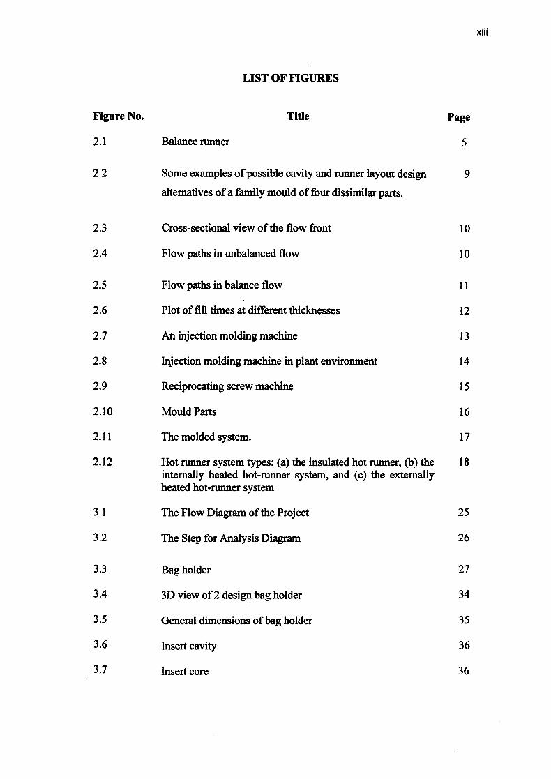
LIST OF FIGURES
Figure No. Title Page
2.1 Balance runner 5
2.2 Some examples of possible cavity and runner layout design 9
alternatives of a family mould of four dissimilar parts.
2.3 Cross-sectional view of the flow front 10
2.4 Flow paths in unbalanced flow 10
2.5 Flow paths in balance flow 11
2.6 Plot of fill times at different thicknesses 12
2.7 An injection molding machine 13
2.8 Injection molding machine in plant environment 14
2.9 Reciprocating screw machine 15
2.10 Mould Parts 16
2.11 The molded system. 17
2.12 Hot runner system types: (a) the insulated hot runner, (b) the 18 internally heated hot-runner system, and (c) the externally heated hot-runner system
3.1 The Flow Diagram of the Project 25
3.2 The Step for Analysis Diagram 26
3.3 Bag holder 27
3.4 3D view of 2 design bag holder 34
3.5 General dimensions of bag holder 35
3.6 Insert cavity 36
3.7 Insert core 36
XIII

3.8 Cavity and core 37
3.9 insert cavity and insert core when assemble 37
3.10 Isometric view 38
3.11 front view and side view 38
4.1 Runner system with dimension 40
4.2 Fill Time for analysis 1 42
4.3 F ill time rate for analysis 1 43
4.4 Pressure for analysis 1 44
4.5 Pressure end of fill for analysis 1 45
4.6 Pressure at v/p switchover for analysis 1 46
4.7 Temperature at flow front for analysis 1 47
4.8 Sink index for analysis 1 48
4.9 weld line for analysis 1 49
4.10 Actual part bag holder fabricated from rapid prototyping 50 used in this study
4.11 Actual part bag holder developed in this study 51
4.12 Simulate model of bag holder using MPI software 51
4.13 Sink index area in simulate model for this study 52
4.14 Area sink mark at actual bag holder 52
4.15 Location of weld line in the simulated model carried out in 53 this study
4.16 The location of weld line (indicated by the weld line) 54
xiv

xv
LIST OF TABLES
Table No. Title Page
2.1 Advantages and disadvantages of hot-runner systems 18
2.2 Other kinds of defects on injection molding process. 21
3.1 Molding temperature for variation of polymer materials 33
4.1 Other paremeters' changes in these 5 different analysis 41
5.1 Summarization of product
52
5.2 Defect prediction before injection 53

LIST OF SYMBOLS
V Velocity
R, r Radius
r Density
T Temperature
11 Shear Viscosity
k Thermal conductivity
€ Strain
P Pressure
a Modulus of Elasticity
Cp Specific heat
D, d Diameter
C Celsius
V Volume
t Time
s second
v/p velocity/peresure
MPa Mega Pascal
xv

LIST OF ABBREAVIATION
MPI Mouldflow Plastic Insight
CAD Computer-Aided Design
CAM Computer-Aided Manufacturing
CAE Computer Aided Engineering
CNC Computer Numeric Control
FMLD Family Mould Layout Design
31) Three Dimensional
PP Polypropylene
PS Polystyrene
PE Polyethylene
PC Polycarbonate
PMMA Poly(rnethacrylic acid)
PA Polyacetylene
PVC Polyvinyl Chloride
PPS Polyphenylene Sulphide
LDPE Low-density Polyethylene
HDPE High-density Polyethylene
ABS Acrylonitrile Butadiene Styrene
HIPS High Impact Polystyrene
AS Acrylonitrile Styrene
PU Polyurethane
PBT Polybutylene Terephthalate
xvii

CHAPTER 1
INTRODUCTION
1.1 INTRODUCTION
In an age of globalization, the technology of the tool and die fabrication in plastic
injection is one of the world's fastest growing industries. Plastic is now used in almost
every application, ranging from household articles to space travel, from transportation to
packing, from medicine to toys, from bridge building to sports. Generally, injection
moulding is a process that forms the plastic into a desired shape by melting the plastic
material and forcing the plastic material under pressure into the mould cavity. The shape of
the plastic that is desired is achieved by cooling in thermoplastic or by chemical reaction
for thermosetting. (Source by Shamsuddin Sulaiman, Napsiah Ismail & A.M.S. Hamouda,
Design and Simulation of Plastic Injection Moulding Process. Department of Mechanical
and Manufacturing Engineering Universiti Putra Malaysia).
Mould design and fabrication is a costly and high technology process because it
uses science-based as mould flow plastic insight (MPI) software to analyse and simulate
the plastic parts, computer-aided design (CAD) software to design the complicated plastic
Product and computer-aided manufacturing (CAM) to do the programming fabrication to
run the computer numerical control (CNC) for milling or latch. Advances in computer
technology have led to an increasingly favorable power to cost ratio for computers. So this
advantageous and costly technology will improve productivity and process consistency.
Thus, for this fast growing industry, new technologies are vital to ensure that this
technology reaches perfection. So mould flow, plastic insight (MPI) is the assistant to
Process and calculate the plastic material flow inside the injection moulding.
I

2
1.1 PROBLEM STATEMENT
In the mould manufacturing nowadays, Family mould is still being used by some
companies especially when the production volume is low and tooling cost is an issue. One
of the above started reason is batch production that becoming common in manufacturing
today. Global market competition and customer demand had lead to shorter product
lifecycle complicated and quality product with competition price and the essence of right
time delivery to market.
Family mould is due to can save money on multiple part types. It consists of a
complete mold with a few or many different cavity inserts that runs as a single part each
cycle or more parts each cycle. Family molds are often utilized when two or more part
designs are similar but not identical, or if mold cost is a driving factor. Two different parts
can be produced from a single mold. This can save on time and expenses by sharing
common mold components such as the mold base, but also allows for a single mold setup.
Family molds are typically better suited for lower volume applications, and
automation may be necessary to separate pieces during or after production. They also have
the potential for greater downtime as repairs and modifications to a single part affect all the
components within the mold. Some of the benefits of a family mold are lost if the parts in
the mold are run in different resins. When designing plastic parts for the injection moulding
process, the important element to understand is how the plastic is filling in the mould. In
the mould injection filling phase, molten plastic is injected into the cavity until the cavity is
just filled. As plastic flows into the cavity, the plastic in contact with the mould wall
quickly freezes and this will create a frozen layer of plastic between the mould and the
molten plastic. The problem also can detect when use mould flow simulation, example
balance flow, clamping force, feed system not balance. In this experiment can know how to
compare from data Autodesk mould flow inside with actual while injection molding.

3
1.2 SIGNIFICANT OF STUDY
There are few significances of this study when objectives have been achieved as
follow:
L We can use simulation software before produce product in injection molding.
Comparison in software analysis.
ii. We can study design balance flow analysis in family mould and optimization
of feed system design.
13 PROJECT OBJECTIVES
The objectives of this study are:
i. To compare mould flow simulation software with actual injection molding
ii. To predict possibility of injection molding defect before injection.
iii. To apply knowledge of machining process into practical way.
1.4 SCOPES OF THE PROJECT
The scopes of this project are limited to:
L Study on feed system design for the gate and runner modeling-critical to
achieving accurate results.
ii. Study on the Optimization of the design to anticipate any molding problems
before the tool is constructed.

CHAPTER 2
LITERATURE REVIEW
2.1 INTRODUCTION
In this research, will discuss about the mould flow simulation software
Mould flow Plastic Insight (MPI). MPI is used to study the effects of feed system
design in family mould. There are a number of factors to consider when designing
the feed system, including the gate locations, the number of cavities, the shape of
the runner system components, and flow balance.
The first step in designing the feed system is to determine the gate locations
for each part in the mold. The rest of the components will fit into place depending
upon each gate location. The objective when designing the feed system is to design
it with balanced flow so that each part in the mold fills at the same rate. The
creation of a well-balanced feed system requires careful consideration the following
elements: [1]
• Single-cavity, multi-cavity, or family mold
• Cavity layout
• Location of the sprue
• Runner system layout
• Shape of the sprue, runners, and gates
4

5
In general, make runners as short as possible, with the lowest possible shot
weight. In the following diagram, the flow length for every part is the same. This is
a naturally balanced runner system [1] . Balance runner as shown in the Figure 2.1
Figure. 2.1: Balance runner
The balancing of the runner system is an iterative, trial-and-error process,
relying heavily on the knowledge and experience of the mold designer. It is
generally a three phase process comprising filling, packing and cooling phases. Its
popularity is typified by the numerous products produced in this way at the present
time by L.W. Scow, Y.C. Lam [2]. These analysis programs can be used by a mold
designer to simulate and balance the runner system of the mold. The goal during
runner balancing is to vary the diameters of the runner segments such that all the
cavities fill at the same time and pressure by Ivan W.M. Chan Martyn Pinfold
C.K. Kwong W.H. Szeto [3].
2.2 MOLD FLOW PLASTIC INSIGHT SOFTWARE
Moldilow Plastic Insight software was developed by Mold flow. Corporation
to aid designers in the plastic industries to:
• reduce product development time and rework, hence decreasing
overall costs

6
reduce manufacturing cycle time;
• improve product design and foresee any problems related to product
manufacturability.
• provide options for various processing parameters and material for
both plastic and composite product.
The software provides simulation modules for various processes such as:
• thermoplastic injection molding;
• gas assisted injection molding
• co-injection molding
• injection-compression molding
• reaction injection molding
• microchip encapsulation
• underfihl encapsulation (flip chip)
Thermoplastic injection molding simulation involves solving the governing
equation of mass, momentum, and energy numerically over the physical domain.
The numerical implementation involves discretizing the physical domain into a
number of sub domains, or elements. The dependent variables (velocity, pressure
and temperature) are approximated within each element.
2.3 PLASTIC SIMULATION
Simulation tools used range from simple, CAD centric filling and gating
studies, to product optimization, highly complex warp predictions, and visco
elasticity load cases. Presented below are some examples of mold flow projects,
many were performed in concert with a design optimization effort prior to tooling
release. There are two major benefits to performing a serious mold flow study prior
to part release.

Optimization of the design to anticipate any molding problems before the
tool is constructed. Capture of the "as-molded" structural properties of the part not
as designed, but as manufactured, enabling highly accurate FEA of the part.
The bottom line-these tools and techniques reduce tool validation times,
decrease or eliminate unanticipated part failures, and provide indicators for
dimensional stability before releasing the part.
Formally the domain of the tool shop, the value of performing these types of
studies as a component of the design and part engineering process is well
established. Review the examples below and see how your project can benefit from
using advanced mold flow simulation.
2.4 MESH ANALYSIS
There are two main prerequisites that must be specified in the model in order
to run a flow analysis. They are:
(i) A meshed part model;
(ii) Specifying injection nodes in a boundary condition file.
There are three main types of mesh provided by this software; midplane,
surface (fusion) and volume (31)) mesh. The clutch pedal model is drawn using the
software attributes and meshed using a midplane mesh. A midplane mesh consists
of three nodded triangular elements located at the half thickness of the part surface.
By stating the thickness of the part, the two-dimensional midplane mesh represents
the solid model during the molding analysis.
2.5 FLOW ANALYSIS
Mould Flow analysis is recommended be performed on this project. This is
because it will assist in identifying potential problems in the molding process and
allow to vary gate location, process conditions, and/or geometry to predict problems

8
and determine solutions. A filling analysis will allow the make these changes before
the tool is cut and will reduce potential costs associated with reworking a tool. The
field of flow analysis has gained increasing importance in injection molding. Flow
analysis has provided rational solution to many of the hard-to-understand effect that
cause problem in he molding process. These effects have including warping,
molded-in stress, excessive fill pressure, part flashing and other.
2.5.1 Advantages of Flow Analysis
The CAE simulation provides engineers, designers, moulders with a visual
and numerical feedback about what actually happens inside the mould cavity during
the injection moulding process.
2.6 FAMILY MOULDS
Cold runner family moulds are widely used in some industries, such as toys
and domestic products, because it is an economical method to produce plastic parts
of different shapes of the same plastic material with a relatively low-dimensional
accuracy requirement for a small-to-medium production volume.
The cost estimation for quotation and themoulding performance of a family
mould are highly dependent on a family mould layout design (FMLD) decision
made during the early mould design phase. It is because FMLD determines many
key design factors such as cavity layout design, runner layout design, mould base
selection, cooling system design and so forth by Ivan W.M. Chan Martyn Pinfold
C.K. Kwong W.H. Szeto [3]
For example, a simple family mould of four dissimilar parts already involves
a number of possible cavity layout and runner layout design alternatives can be see
in Figure 8. Design alternative (a) seems to be the best one because of its compact

and balanced layout, but it requires two individual sliders for part 2 and part 3.
Design alternative (h) can save cost by combining the two individual sliders into
one but at the expense of an unbalanced layout and larger mould base. In some
cases, a larger mould base is not preferable or even not allowed due to the
insufficient space of the mould platen of a customer's molding machine. Layout
possible cavity and runner respectively as shown in the Figure 2.2 by Ivan W.M.
Chan Martyn Pinfold C.K. Kwong W.H. Szeto [3].
cavity mould insert
1 E slider
a runner
0
U!.
U
0
onw
Figure 2.2: Some examples of possible cavity and runner layout design
alternatives of a family mould of four dissimilar parts
(Source by Ivan W.M. Chan Martyn Pinfold • C.K. Kwong W.H. Szeto, A review of research, commercial software packages and patents on family mould layout design
automation and optimisation, hit J Adv Manuf Technol 2011)

10
Simulation software solves the governing equation of mass,
momentum,band energy of injection moulding process numerically. Simulation of
filling and packing phase of injection moulding process depends on accurate
characterization of the material properties by Iwan Halim Sahputra [7]
2.7 GOVERNING EQUATIONS
Plastic flow in the filling phase is like flow between two plates separated by
a small distance. This is well modelled by the Hele-Shaw approximation in general
by L.W. Scow, Y.C. Lam [2]. Assuming an incompressible, generalized, non-
Newtonian fluid, the equations for the filling phase can be written as:
Frozen Layer I I ow waN
Z
WK Front
— - — - — - — \---- 12h
Figure 2.3: Cross-sectional view of the flow front
IlFiow Front I
Figure 2.4: Flow paths in unbalanced flow

Continuity equation:
(1)
& —+--±—=o ox cij Oz
Momentum Equation:
Op 0 ( iiu
Ox TZ
ap (7 Ov
- Oz Oz
Energy Equation:
(LaTtOT OT\ 02T
pC1 + u---± 'jy- +k 0z2
where (x, y, z) are the Cartesian coordinates and (u, v, w) are the velocity
components, respectively. T is the temperature, p the pressure, r is the density, Cp is
the specific heat and k is the thermal conductivity of the material whilst q is the
shear viscosity where the shear rate y is:
(4)
F(Ly+\zJ \Oz
Following the treatment by Kennedy [5], the continuity and momentum
equations can be combined to yield:
(5)
11
(2)
(3)

- 0X \, aX j aj
(sip)
12
Where
Flow Pethsl
Figure 2.5: Flow paths in balance flow
Plot of fill time vs thickness 1.6 1.4 1.2
U a, a,
a,
0.4
00 0.5 1 1.5
lIt(mm-1)
Figure 2.6: Plot of fill times at different thicknesses.
(6)
s= I (12)dz