Embed Size (px)
Citation preview
Optimization of a New Design of Molten Salt-to-CO2 1
Heat Exchanger using Exergy Destruction 2
Minimization 3
María José Montes1*, José Ignacio Linares2, Rubén Barbero1, Beatriz Yolanda Moratilla2 4 1 E.T.S. Ingenieros Industriales - UNED, C/Juan del Rosal 12, 28040 Madrid, Spain; [email protected] 5 2 Rafael Mariño Chair in New Energy Technologies – COMILLAS-ICAI, C/Alberto Aguilera 25, 28015 6
Madrid, Spain; [email protected] 7 * Correspondence: [email protected]; Tel.: +34 91 398 64 65 (F.L.) 8 Received: date; Accepted: date; Published: date 9
Abstract: One of the ways to make cost-competitive electricity, from concentrated solar thermal 10 energy, is increasing the thermoelectric conversion efficiency. To achieve this objective, the most 11 promising scheme is a molten salt central receiver, coupled to a supercritical carbon dioxide cycle. 12 A key element to be developed in this scheme is the molten salt-to-CO2 heat exchanger. This paper 13 presents a heat exchanger design that avoids the molten salt plugging and the mechanical stress due 14 to the high pressure of the CO2, while improving the heat transfer of the supercritical phase, due to 15 its compactness with a high heat transfer area. This design is based on a honeycomb-like 16 configuration, in which a thermal unit consists of a circular channel for the molten salt surrounded 17 by six smaller trapezoidal ducts for the CO2. Further, an optimization based on the exergy 18 destruction minimization has been accomplished, obtained the best working conditions of this heat 19 exchanger: a temperature approach of 50 ˚C between both streams and a CO2 pressure drop of 2.7 20 bar. 21
Keywords: Solar Thermal Power Plants; Supercritical CO2 cycles; MS-to-CO2 Heat Exchanger; 22 Thermo-economic optimization; exergy destruction minimization 23
24
1. Introduction 25 The main advantages of the energy supplied through Solar Thermal Power Plants (STPPs) are 26
its capacity, reliability and stability to the grid, which in turn allows the renewable electricity 27 percentage to be also higher. However, when compared to the costs of solar photovoltaic electricity, 28 the reduction in cost must still be very large for solar thermal electricity, to be competitive. One of 29 the ways to achieve this is by increasing global conversion efficiency by coupling the solar field to a 30 supercritical cycle. In this scheme, a reliable design of the heat exchanger between the solar field and 31 the Brayton cycle is essential for the technical viability of these STPPs. 32
Within the SunShot program [1], the U.S Department of Energy (DOE) has identified three 33 potential schemes for the next generation of STPPs, based on the Heat Transfer Fluid (HTF) in the 34 receiver: molten salts, falling particles or gas phase. In all the schemes, the solar field is coupled to a 35 supercritical carbon dioxide (sCO2) cycle, achieving high thermo-electric conversion efficiency. 36
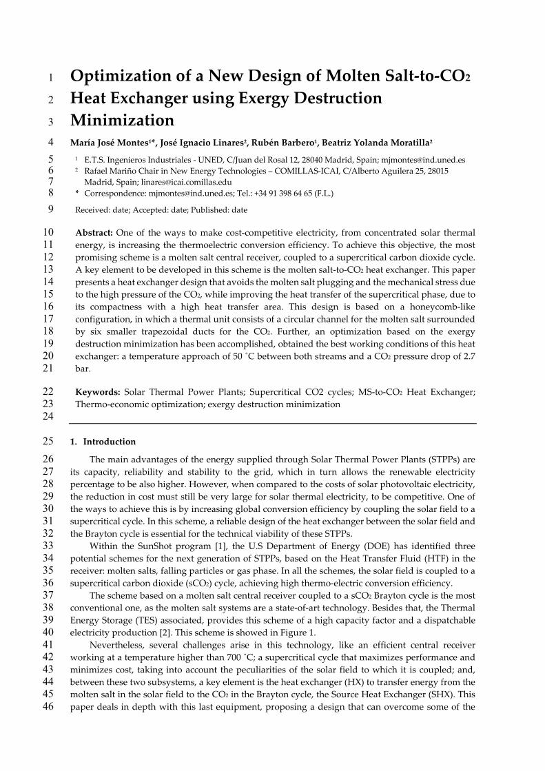
The scheme based on a molten salt central receiver coupled to a sCO2 Brayton cycle is the most 37 conventional one, as the molten salt systems are a state-of-art technology. Besides that, the Thermal 38 Energy Storage (TES) associated, provides this scheme of a high capacity factor and a dispatchable 39 electricity production [2]. This scheme is showed in Figure 1. 40
Nevertheless, several challenges arise in this technology, like an efficient central receiver 41 working at a temperature higher than 700 ˚C; a supercritical cycle that maximizes performance and 42 minimizes cost, taking into account the peculiarities of the solar field to which it is coupled; and, 43 between these two subsystems, a key element is the heat exchanger (HX) to transfer energy from the 44 molten salt in the solar field to the CO2 in the Brayton cycle, the Source Heat Exchanger (SHX). This 45 paper deals in depth with this last equipment, proposing a design that can overcome some of the 46
2 of 21
technological difficulties of these type of HXs: the mechanical stress due to the high pressure of the 47 supercritical phase; the need of improving the heat transfer of the supercritical fluid; and overall, the 48 molten salt plugging in the microchannels of a Compact Heat Exchanger (CHX), as it will be 49 explained below. 50
51
52 Figure 1. Scheme of the complete STPP with the CHHE between the solar field and the sCO2 cycle 53
54 Supercritical CO2 Brayton cycles have a very high efficiency, above 50%, even with dry-cooling 55
[3], so their integration in a STPP can yield to an overall performance increase. Wang et al. [4] 56 identified six possible supercritical cycles that can be integrated in a molten salt central receiver 57 system with thermal storage: simple recovery cycle; recompression cycle; precompression cycle; 58 intercooling cycle; partial-cooling cycle; and split expansion cycle. These cycles can be assessed 59 according to different parameters, being the most important ones: the cycle efficiency; the complexity 60 of the cycle compared to the most conventional one, the recompression cycle (represented in figure 61 1); and the CO2 temperature increment in the source heat exchanger, as this value determines the 62 molten salt volume in the solar field. 63
The intercooling cycle is the one with higher thermal efficiency when the thermal source 64 temperature ranges from 600 ˚C to 800 ˚C, followed by the recompression cycle, that is also the 65 simplest. Regarding the temperature difference in the source heat exchanger, the partial cooling 66 layout is the one with the largest increment. In summary, three cycles can be identified to be the most 67 suitable for coupling to a molten salt central receiver: recompression cycle, intercooling cycle and 68 partial-cooling cycle [4-5] 69
The central receiver is usually a external-type with a surrounding heliostat field [1], although 70 the cavity-type is recommended in recent investigations when the working temperature is high [2], 71 because the radiation heat loss is lower compared to external receivers working at the same 72 temperature. At last, the molten salt thermal storage consists of two tanks of molten salts, which 73 have been sized to provide the nominal thermal power to the supercritical cycle for 6 hours, with a 74 charging time of 6 hours. 75
This paper is focused in the heat exchanger between the solar field and the supercritical cycle, 76 so a literature review on this heat exchanger is presented below. 77
There are several designs proposed in the literature for MS-to-CO2 heat exchangers, for both 78 nuclear and solar applications, since both technologies use the scheme of a thermal source coupled 79 to a supercritical CO2 cycle, as an alternative to increase performance. 80
The simplest design for this heat exchanger is a Shell and Tube Heat Exchanger (STHX), in which 81 the CO2 at supercritical pressure circulates inside the tubes, and the molten salt trough the shell. This 82 HX is well suited in supercritical cycles in which the source thermal energy is supplied through the 83 low pressure side of the layout (85 bar approximately), as the one presented in [6]. Nevertheless, if a 84 conventional supercritical cycle is used, the turbine inlet pressure should be limited to 200 bar, which 85 constrains the cycle efficiency. There are several reasons that make the STHX not the most 86
3 of 21
appropriate in conventional supercritical cycles: the great tube thickness due to the high pressure of 87 the CO2 yields to a limited heat transfer and performance [7]; and, although the molten salt plugging 88 does not occur in the shell, this fluid can be kept retained in the baffles and interstices of the HX, also 89 yielding to a reduction in the heat transfer [8-9]. 90
A more advanced design is the Printed Circuit Heat Exchanger (PCHE), which consists of plate 91 sheets joined by diffusion-bonding, alternating hot-cold rows of semi-circular channels [10-11]. These 92 microchannels withstand the high pressure of the CO2 (180 – 300 bar, approximately), and they also 93 improve the heat transfer of this fluid, as the convection coefficient and the hydraulic diameter are 94 inversely related. Nevertheless, PCHEs have the drawback of the viscous molten salt plugging in the 95 microchannels. This issue has been studied in several reports of both nuclear [12] and solar [13] power 96 plants, but very few designs address this problem. The most recent designs of MS-to-CO2 based on 97 PCHE are focused on the heat transfer improvement by using airfoil fins in the microchannels [14-98 16] 99
Only one design has been found in the bibliography that tries to solve the problem of the molten 100 salt plugging in microchannels [17]; the basic principle of this design is to face two plate sheets 101 intended for molten salt, so that a circular channel is formed for this fluid, whereas the CO2 still 102 circulates through semi-circular channels. Although this design does not optimize the heat transfer, 103 the plugging and corrosion problems of the MS are reduced; nevertheless, the channel dimension for 104 the molten salt is still small. 105
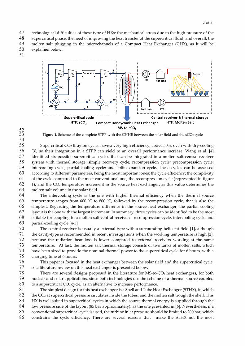
To overcome the problems detailed in the two HX configurations described above, this work 106 proposes and studies a new MS-to-CO2 HX design. From the analysis of the state of the art, it is clear 107 that it would be desirable to increase the ratio of heat transfer area compared to the volume of the 108 HX, that is, the most suitable design is a Compact Heat Exchanger (CHX); the lower convection 109 coefficient of the supercritical phase is compensated by the larger area to transfer the thermal energy. 110 But, at the same time, the MS channel must be larger enough to avoid plugging. To meet both 111 conditions, a small compact shell and tube design [18] has been modified for the thermal duty and 112 working pressure required by the supercritical cycle. The cross section of this design is a compact 113 shell consisting of many thermal units like the one shown in Figure 2. The MS goes through a circular 114 duct that is surrounded by 6 trapezoidal ducts, through which the CO2 circulates. Repetition of this 115 unit gives the cross section of the shell a honeycomb-like appearance. Because of that, this HX will be 116 referred as Compact Honeycomb Heat Exchanger (CHHE). 117
118
119 Figure 2. Cross section of the Compact Honeycomb Heat Exchanger and thermal unit. 120
121
4 of 21
The thermo-mechanic model of this CHHE is explained in section 2; an optimization of this 122 design is accomplished in section 3, by means of an exergy destruction minimization. As a result, the 123 optimum working conditions of this design are set in section 4. 124
2. Thermal model and boundary conditions of the Compact Honeycomb Heat Exchanger 125
2.1. Thermal inputs and boundary conditions from the supercritical cycle and the solar field 126
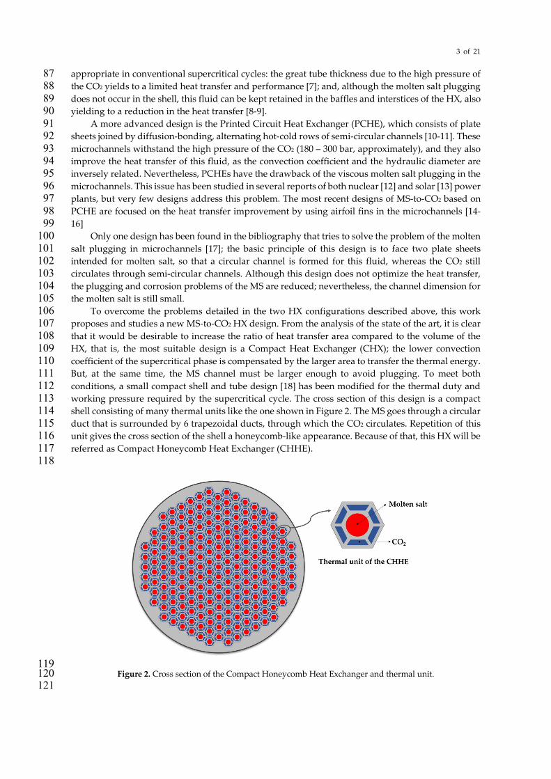
The CHHE is located between the supercritical cycle and the solar field as shown in Figure 1. 127 The supercritical cycle is a conventional recompression cycle that is one of the three layouts (with the 128 partial cooling and the intercooling) that show better characteristics to be coupled to a molten salt 129 solar tower plant [4-5]. The cycle power output is 50 MWe, for which, the thermal energy in the CHHE 130 is 100.99 MWth. Table 1 shows the thermodynamic properties of the state points following the 131 numbering marked in Figure 1. 132
Table 1. Thermodynamic properties of the state points of the recompression sCO2 cycle. 133
Recompression cycle
P (bar) T (˚C) h (kJ/kg)
1 200 688 701.3
2 86.2 574.1 566.5
3 85.8 224.2 158.4
4 85.4 122.9 39.09
5 85 50 -80.9
6 201.2 118.3 -41.57
7 200.8 219.6 117.4
8 200.8 212 107.2
9 200.8 217.7 114.9
10 200.4 545.6 522.9
Cycle power (MWe) 50.00
Source thermal power (MWth) 100.99
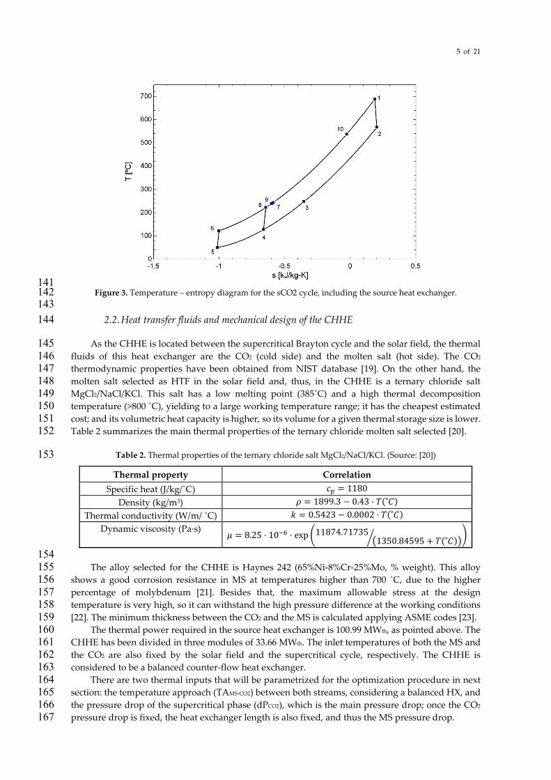
Cycle efficiency (%) 49.57 134 Figure 3 shows the temperature-entropy diagram of this supercritical cycle. As it can be seen, 135
this cycle is characterized by two compressors (processes 5-6 and 4-8) and two recuperators, for low 136 and high temperature (LTR and HTR, respectively). The source heat exchanger is characterized by 137 process 10-1. 138
139 140
5 of 21
141 Figure 3. Temperature – entropy diagram for the sCO2 cycle, including the source heat exchanger. 142
143 2.2. Heat transfer fluids and mechanical design of the CHHE 144
As the CHHE is located between the supercritical Brayton cycle and the solar field, the thermal 145 fluids of this heat exchanger are the CO2 (cold side) and the molten salt (hot side). The CO2 146 thermodynamic properties have been obtained from NIST database [19]. On the other hand, the 147 molten salt selected as HTF in the solar field and, thus, in the CHHE is a ternary chloride salt 148 MgCl2/NaCl/KCl. This salt has a low melting point (385˚C) and a high thermal decomposition 149 temperature (>800 ˚C), yielding to a large working temperature range; it has the cheapest estimated 150 cost; and its volumetric heat capacity is higher, so its volume for a given thermal storage size is lower. 151 Table 2 summarizes the main thermal properties of the ternary chloride molten salt selected [20]. 152
Table 2. Thermal properties of the ternary chloride salt MgCl2/NaCl/KCl. (Source: [20]) 153
Thermal property Correlation
Specific heat (J/kg/˚C) 𝑐𝑐𝑝𝑝 = 1180 Density (kg/m3) 𝜌𝜌 = 1899.3 − 0.43 · 𝑇𝑇(˚𝐶𝐶)
Thermal conductivity (W/m/ ˚C) 𝑘𝑘 = 0.5423 − 0.0002 · 𝑇𝑇(˚𝐶𝐶) Dynamic viscosity (Pa·s)
𝜇𝜇 = 8.25 · 10−6 · exp �11874.71735�1350.84595 + 𝑇𝑇(˚𝐶𝐶)�� �
154 The alloy selected for the CHHE is Haynes 242 (65%Ni-8%Cr-25%Mo, % weight). This alloy 155
shows a good corrosion resistance in MS at temperatures higher than 700 ˚C, due to the higher 156 percentage of molybdenum [21]. Besides that, the maximum allowable stress at the design 157 temperature is very high, so it can withstand the high pressure difference at the working conditions 158 [22]. The minimum thickness between the CO2 and the MS is calculated applying ASME codes [23]. 159
The thermal power required in the source heat exchanger is 100.99 MWth, as pointed above. The 160 CHHE has been divided in three modules of 33.66 MWth. The inlet temperatures of both the MS and 161 the CO2 are also fixed by the solar field and the supercritical cycle, respectively. The CHHE is 162 considered to be a balanced counter-flow heat exchanger. 163
There are two thermal inputs that will be parametrized for the optimization procedure in next 164 section: the temperature approach (TAMS-CO2) between both streams, considering a balanced HX, and 165 the pressure drop of the supercritical phase (dPCO2), which is the main pressure drop; once the CO2 166 pressure drop is fixed, the heat exchanger length is also fixed, and thus the MS pressure drop. 167
6 of 21
For a particular value of each of the previous two parameters (TAMS-CO2 and dPCO2), the outlet 168 temperatures and the velocities of both streams are fixed. In this way, all the thermophysical 169 properties that define the heat exchanger are established. 170
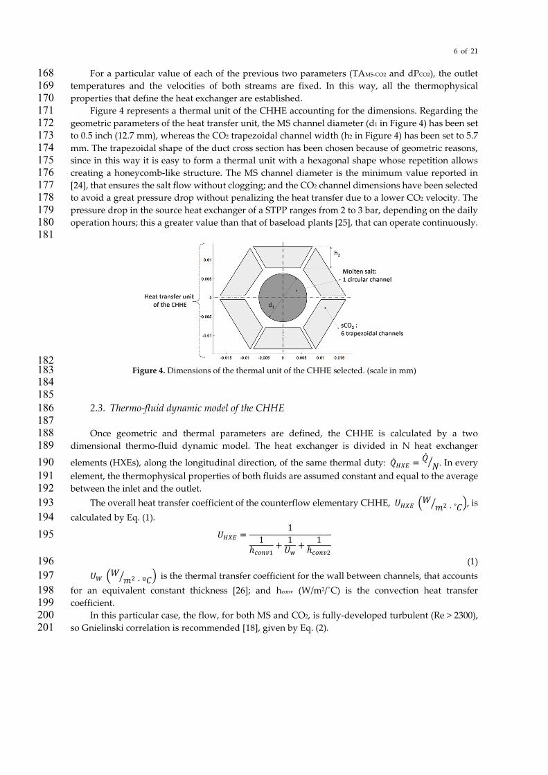
Figure 4 represents a thermal unit of the CHHE accounting for the dimensions. Regarding the 171 geometric parameters of the heat transfer unit, the MS channel diameter (d1 in Figure 4) has been set 172 to 0.5 inch (12.7 mm), whereas the CO2 trapezoidal channel width (h2 in Figure 4) has been set to 5.7 173 mm. The trapezoidal shape of the duct cross section has been chosen because of geometric reasons, 174 since in this way it is easy to form a thermal unit with a hexagonal shape whose repetition allows 175 creating a honeycomb-like structure. The MS channel diameter is the minimum value reported in 176 [24], that ensures the salt flow without clogging; and the CO2 channel dimensions have been selected 177 to avoid a great pressure drop without penalizing the heat transfer due to a lower CO2 velocity. The 178 pressure drop in the source heat exchanger of a STPP ranges from 2 to 3 bar, depending on the daily 179 operation hours; this a greater value than that of baseload plants [25], that can operate continuously. 180
181
182 Figure 4. Dimensions of the thermal unit of the CHHE selected. (scale in mm) 183
184 185
2.3. Thermo-fluid dynamic model of the CHHE 186 187 Once geometric and thermal parameters are defined, the CHHE is calculated by a two 188
dimensional thermo-fluid dynamic model. The heat exchanger is divided in N heat exchanger 189 elements (HXEs), along the longitudinal direction, of the same thermal duty: �̇�𝑄𝐻𝐻𝐻𝐻𝐸𝐸 = �̇�𝑄
𝑁𝑁� . In every 190 element, the thermophysical properties of both fluids are assumed constant and equal to the average 191 between the inlet and the outlet. 192
The overall heat transfer coefficient of the counterflow elementary CHHE, 𝑈𝑈𝐻𝐻𝐻𝐻𝐸𝐸 �𝑊𝑊 𝑚𝑚2 · ˚𝐶𝐶� �, is 193 calculated by Eq. (1). 194
𝑈𝑈𝐻𝐻𝐻𝐻𝐸𝐸 =1
1ℎ𝑐𝑐𝑐𝑐𝑐𝑐𝑐𝑐1
+ 1𝑈𝑈𝑤𝑤
+ 1ℎ𝑐𝑐𝑐𝑐𝑐𝑐𝑐𝑐2
195
(1) 196 𝑈𝑈𝑊𝑊 �𝑊𝑊 𝑚𝑚2 · º𝐶𝐶� � is the thermal transfer coefficient for the wall between channels, that accounts 197
for an equivalent constant thickness [26]; and hconv (W/m2/˚C) is the convection heat transfer 198 coefficient. 199
In this particular case, the flow, for both MS and CO2, is fully-developed turbulent (Re > 2300), 200 so Gnielinski correlation is recommended [18], given by Eq. (2). 201
7 of 21
𝑁𝑁𝑁𝑁𝐷𝐷ℎ =(𝑓𝑓𝑐𝑐 8⁄ ) · (𝑅𝑅𝑅𝑅𝐷𝐷ℎ − 1000) · 𝑃𝑃𝑃𝑃
1 + 12.7 · ��𝑓𝑓𝑐𝑐8� · (𝑃𝑃𝑃𝑃2 3⁄ − 1)· �
𝑃𝑃𝑃𝑃𝑃𝑃𝑃𝑃𝑠𝑠𝑠𝑠
�0.11
𝑤𝑤ℎ𝑅𝑅𝑃𝑃𝑅𝑅:
𝑓𝑓𝑐𝑐 = [1.82 · 𝑙𝑙𝑙𝑙𝑙𝑙(𝑅𝑅𝑅𝑅𝐷𝐷ℎ) − 1.64]−2
202
(2) 203 This correlation is valid for Reynolds numbers ranging from 2300 to 5x10⁵ and Prandtl numbers 204
from 0.5 to 2000. In the above equation fc is the friction factor, calculated as needed from the Filonenko 205 correlation [27]; ReDh is the Reynolds number based on the inner hydraulic diameter; Pr is Prandtl 206 number at the bulk fluid temperature; Prsi is the Prandtl number at the inner duct temperature, tsi. 207
In case of laminar flow (only for molten salt under particular conditions), the Nusselt number is 208 constant, as seen in Eq. (3). 209
𝑁𝑁𝑁𝑁 = 4.3636 𝑓𝑓𝑙𝑙𝑃𝑃 𝑅𝑅𝑅𝑅𝐷𝐷ℎ < 2300 210
(3) 211
Once the value of the global heat transfer coefficient is known, length of every HXE is calculated 212 by means of the basic equation of heat transfer, Eq. (4). 213
�̇�𝑄𝐻𝐻𝐻𝐻𝐸𝐸 = 𝑈𝑈𝐻𝐻𝐻𝐻𝐸𝐸 · 𝐴𝐴𝐻𝐻𝐻𝐻𝐸𝐸 · ∆𝑇𝑇𝑚𝑚 214
(4) 215 �̇�𝑄𝐻𝐻𝐻𝐻𝐸𝐸(𝑊𝑊) is the thermal duty of every HXE; 𝐴𝐴𝐻𝐻𝐻𝐻𝐸𝐸 (𝑚𝑚2) is the heat transfer area of every HXE; 216
∆𝑇𝑇𝑚𝑚(ºC) is the mean temperature, that is constant, as the CHHE is balanced and the CO2 is considered 217 as an ideal gas. The length of every HXE, 𝐿𝐿𝐻𝐻𝐻𝐻𝐸𝐸 (𝑚𝑚) , is calculated from the heat transfer area, 218 𝐴𝐴𝐻𝐻𝐻𝐻𝐸𝐸 (𝑚𝑚2). 219
Finally, friction pressure destruction is calculated by means of the Darcy-Weisbach equation 220 [18], for both fluids: 221
∆𝑃𝑃𝑠𝑠 =12
· 𝑓𝑓𝐷𝐷,𝑠𝑠 · �𝐿𝐿𝐻𝐻𝐻𝐻𝐸𝐸𝐷𝐷ℎ,𝑠𝑠
� · 𝜌𝜌𝑎𝑎𝑐𝑐𝑎𝑎,𝑠𝑠 · 𝑁𝑁𝑎𝑎𝑐𝑐𝑎𝑎,𝑠𝑠2 222
(5) 223 Where Dh (m) is the hydraulic diameter of the duct; ρ (kg/m3) is the average fluid density; u (m/s) 224
is the average fluid velocity; and fD is the Darcy friction factor, that is calculated by the Techo et al. 225 correlation [18], for turbulent flow (104 ≤ 𝑅𝑅𝑅𝑅𝐷𝐷ℎ ≤ 107); or the Hägen-Poiseulle correlation [18], in case 226 of laminar flow (𝑅𝑅𝑅𝑅𝐷𝐷ℎ ≤ 2300); finally, the subindex i refers to the each fluid: molten salt or CO2. 227
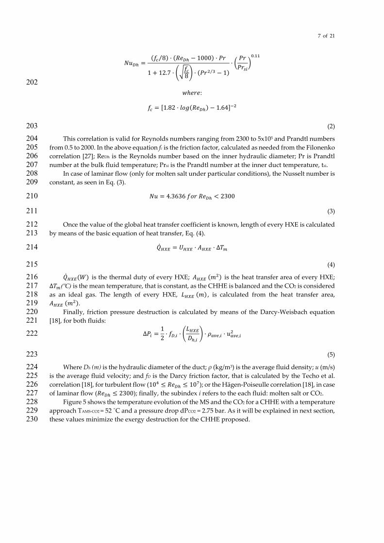
Figure 5 shows the temperature evolution of the MS and the CO2 for a CHHE with a temperature 228 approach TAMS-CO2 = 52 ˚C and a pressure drop dPCO2 = 2.75 bar. As it will be explained in next section, 229 these values minimize the exergy destruction for the CHHE proposed. 230
8 of 21
231 Figure 5. Temperature evolution of the ternary chloride molten salt and the CO2 along the CHHE 232
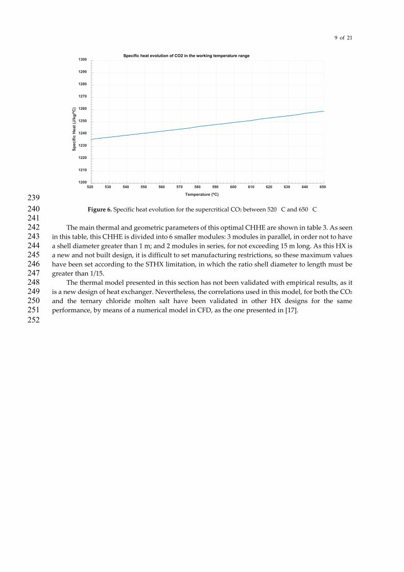
233 From Figure 5, it is concluded that temperature evolution is almost lineal for both streams, which 234
means that specific heat is nearly constant. This is clear for the molten salt, which is an incompressible 235 fluid approximately, but also for the supercritical CO2, as this fluid is at very high temperature and 236 far away from the critical point. Figure 6 shows that specific heat ranges from 1.236 kJ/kg/˚C to 1.258 237 kJ/kg/˚C in the working temperature values (from 520 ˚C to 650 ˚C). 238
0 1 2 3 4 5 6 7 8 9 10 11 12 13 14 15 16 17 18 19 20 21 22 23 24
Heat exchanger length (m)
500510520530540550560570580590600610620630640650660670680690700
Tem
pera
ture
(ºC
)
Temperature evolution of MS and CO2 along the CHHE
Molten salt temperature (ºC)CO2 temperature (ºC)
Temperature
9 of 21
239 Figure 6. Specific heat evolution for the supercritical CO2 between 520 C and 650 C 240
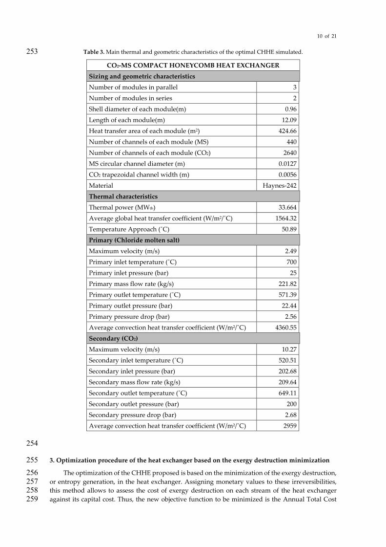
241 The main thermal and geometric parameters of this optimal CHHE are shown in table 3. As seen 242
in this table, this CHHE is divided into 6 smaller modules: 3 modules in parallel, in order not to have 243 a shell diameter greater than 1 m; and 2 modules in series, for not exceeding 15 m long. As this HX is 244 a new and not built design, it is difficult to set manufacturing restrictions, so these maximum values 245 have been set according to the STHX limitation, in which the ratio shell diameter to length must be 246 greater than 1/15. 247
The thermal model presented in this section has not been validated with empirical results, as it 248 is a new design of heat exchanger. Nevertheless, the correlations used in this model, for both the CO2 249 and the ternary chloride molten salt have been validated in other HX designs for the same 250 performance, by means of a numerical model in CFD, as the one presented in [17]. 251 252
520 530 540 550 560 570 580 590 600 610 620 630 640 650
Temperature (ºC)
1200
1210
1220
1230
1240
1250
1260
1270
1280
1290
1300
Spec
ific
Hea
t (J/
kg/ºC
)
Specific heat evolution of CO2 in the working temperature range
10 of 21
Table 3. Main thermal and geometric characteristics of the optimal CHHE simulated. 253
CO2-MS COMPACT HONEYCOMB HEAT EXCHANGER
Sizing and geometric characteristics
Number of modules in parallel 3
Number of modules in series 2
Shell diameter of each module(m) 0.96
Length of each module(m) 12.09
Heat transfer area of each module (m2) 424.66
Number of channels of each module (MS) 440
Number of channels of each module (CO2) 2640
MS circular channel diameter (m) 0.0127
CO2 trapezoidal channel width (m) 0.0056
Material Haynes-242
Thermal characteristics
Thermal power (MWth) 33.664
Average global heat transfer coefficient (W/m2/˚C) 1564.32
Temperature Approach (˚C) 50.89
Primary (Chloride molten salt)
Maximum velocity (m/s) 2.49
Primary inlet temperature (˚C) 700
Primary inlet pressure (bar) 25
Primary mass flow rate (kg/s) 221.82
Primary outlet temperature (˚C) 571.39
Primary outlet pressure (bar) 22.44
Primary pressure drop (bar) 2.56
Average convection heat transfer coefficient (W/m2/˚C) 4360.55
Secondary (CO2)
Maximum velocity (m/s) 10.27
Secondary inlet temperature (˚C) 520.51
Secondary inlet pressure (bar) 202.68
Secondary mass flow rate (kg/s) 209.64
Secondary outlet temperature (˚C) 649.11
Secondary outlet pressure (bar) 200
Secondary pressure drop (bar) 2.68
Average convection heat transfer coefficient (W/m2/˚C) 2959
254
3. Optimization procedure of the heat exchanger based on the exergy destruction minimization 255 The optimization of the CHHE proposed is based on the minimization of the exergy destruction, 256
or entropy generation, in the heat exchanger. Assigning monetary values to these irreversibilities, 257 this method allows to assess the cost of exergy destruction on each stream of the heat exchanger 258 against its capital cost. Thus, the new objective function to be minimized is the Annual Total Cost 259
11 of 21
(ATC), which takes into account the investment cost and the operation cost, including the 260 irreversibilities in this last one. 261
𝐴𝐴𝑇𝑇𝐶𝐶 = 𝐶𝐶𝑅𝑅𝐶𝐶 · 𝐶𝐶𝐶𝐶 + 𝐶𝐶𝐶𝐶𝐿𝐿𝐶𝐶 · 𝐶𝐶𝐸𝐸 · 𝑌𝑌 · ∆�̇�𝐶𝑥𝑥𝑑𝑑𝑎𝑎𝑠𝑠𝑑𝑑𝑑𝑑𝑐𝑐𝑑𝑑𝑎𝑎𝑑𝑑 262
(6) 263
In equation (6), CRF is the capital-recovery factor and CELF is the constant-escalation 264 levelization factor, both defined below; CE is the cost per unit of exergy ($/Wh), which has been taken 265 as 0.00005 $/Wh, according to several references [28-29]; Y is the yearly operation time, calculated for 266 a solar multiple equal to 2: Y= 365*12 hours; CC is the investment cost of the CHHE; finally, 267 ∆�̇�𝐶𝑥𝑥𝑑𝑑𝑎𝑎𝑠𝑠𝑑𝑑𝑑𝑑𝑐𝑐𝑑𝑑𝑎𝑎𝑑𝑑 is the total exergy destruction due to the most important irreversibilities in the heat 268 exchanger. 269
The capital-recovery factor (CRF) and the constant-escalation levelization factor (CELF) are 270 calculated by means of Eq. (7) and Eq. (8). 271
𝐶𝐶𝑅𝑅𝐶𝐶 =𝑖𝑖𝑎𝑎𝑒𝑒𝑒𝑒 · �1 + 𝑖𝑖𝑎𝑎𝑒𝑒𝑒𝑒�
𝑐𝑐
�1 + 𝑖𝑖𝑎𝑎𝑒𝑒𝑒𝑒�𝑐𝑐 − 1
272
(7) 273
𝐶𝐶𝐶𝐶𝐿𝐿𝐶𝐶 = 𝐶𝐶𝑅𝑅𝐶𝐶 ·𝑘𝑘 · (1 − 𝑘𝑘𝑐𝑐 )
(1 − 𝑘𝑘)
𝑤𝑤ℎ𝑅𝑅𝑃𝑃𝑅𝑅
𝑘𝑘 =1 + 𝑃𝑃𝑐𝑐
1 + 𝑖𝑖𝑎𝑎𝑒𝑒𝑒𝑒
274
(8) 275
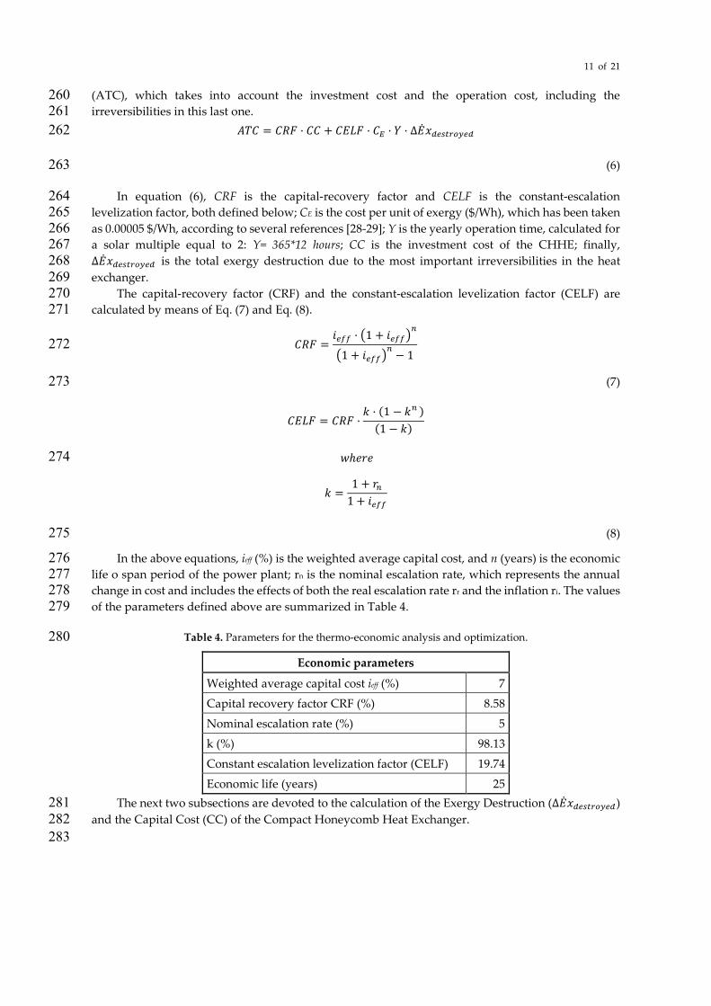
In the above equations, ieff (%) is the weighted average capital cost, and n (years) is the economic 276 life o span period of the power plant; rn is the nominal escalation rate, which represents the annual 277 change in cost and includes the effects of both the real escalation rate rr and the inflation ri. The values 278 of the parameters defined above are summarized in Table 4. 279
Table 4. Parameters for the thermo-economic analysis and optimization. 280
Economic parameters
Weighted average capital cost ieff (%) 7
Capital recovery factor CRF (%) 8.58
Nominal escalation rate (%) 5
k (%) 98.13
Constant escalation levelization factor (CELF) 19.74
Economic life (years) 25 The next two subsections are devoted to the calculation of the Exergy Destruction (∆�̇�𝐶𝑥𝑥𝑑𝑑𝑎𝑎𝑠𝑠𝑑𝑑𝑑𝑑𝑐𝑐𝑑𝑑𝑎𝑎𝑑𝑑) 281
and the Capital Cost (CC) of the Compact Honeycomb Heat Exchanger. 282 283
12 of 21
3.1. Accounting for the exergy destruction in the CHHE. 284
Many researchers [30-31] have used the minimization of entropy generation, or exergy 285 destruction, method to optimize the design of heat exchangers. 286
The causes of exergy destruction in a heat exchanger are: the finite temperature difference 287 between hot and cold fluids, pressure drops on both fluids, and exergy losses associated to the non-288 adiabatic condition of a real heat exchanger, with a heat leakage with the environment; taking the 289 limit of the system in the outer wall of the heat exchanger, these exergy losses constitute external 290 irreversibilities to the heat exchanger. 291
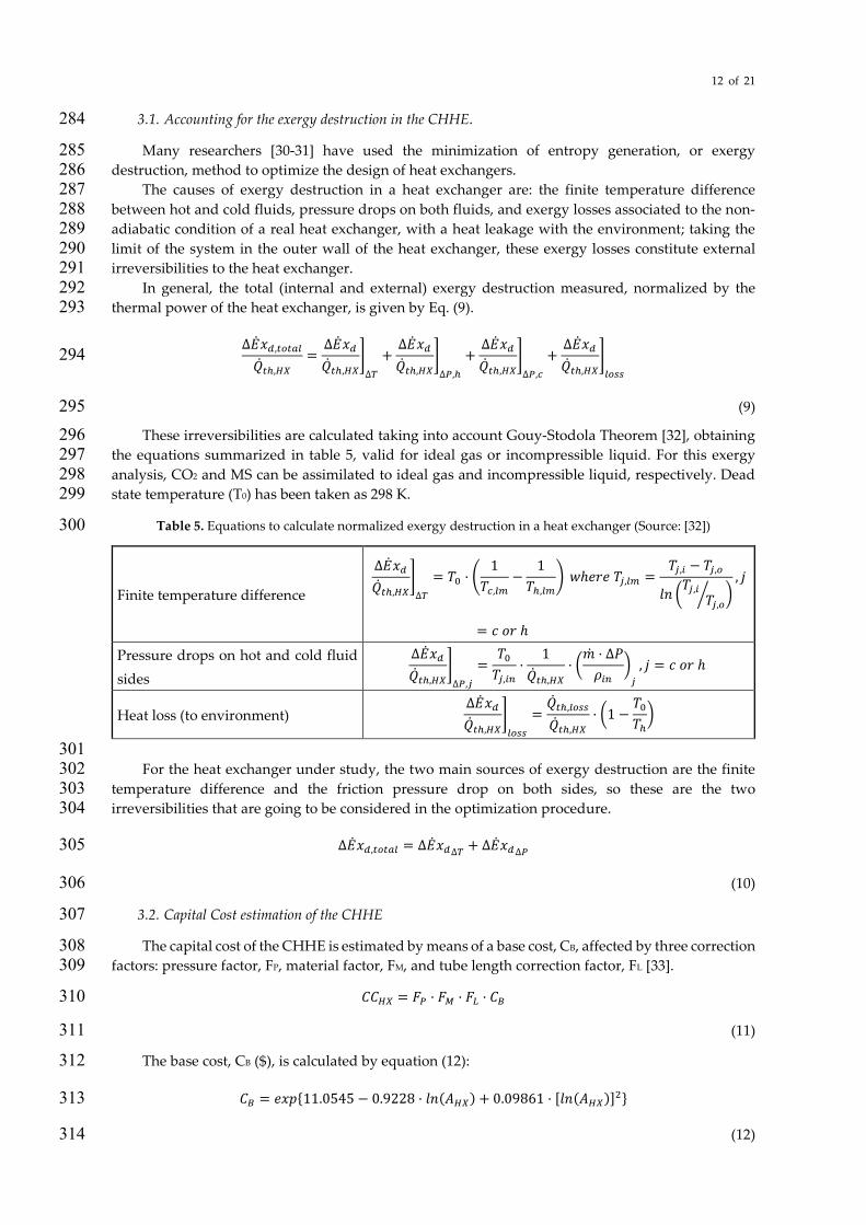
In general, the total (internal and external) exergy destruction measured, normalized by the 292 thermal power of the heat exchanger, is given by Eq. (9). 293
∆�̇�𝐶𝑥𝑥𝑑𝑑,𝑑𝑑𝑐𝑐𝑑𝑑𝑎𝑎𝑡𝑡
�̇�𝑄𝑑𝑑ℎ,𝐻𝐻𝐻𝐻=∆�̇�𝐶𝑥𝑥𝑑𝑑�̇�𝑄𝑑𝑑ℎ,𝐻𝐻𝐻𝐻
�∆𝑇𝑇
+∆�̇�𝐶𝑥𝑥𝑑𝑑�̇�𝑄𝑑𝑑ℎ,𝐻𝐻𝐻𝐻
�∆𝑃𝑃,ℎ
+∆�̇�𝐶𝑥𝑥𝑑𝑑�̇�𝑄𝑑𝑑ℎ,𝐻𝐻𝐻𝐻
�∆𝑃𝑃,𝑐𝑐
+∆�̇�𝐶𝑥𝑥𝑑𝑑�̇�𝑄𝑑𝑑ℎ,𝐻𝐻𝐻𝐻
�𝑡𝑡𝑐𝑐𝑠𝑠𝑠𝑠
294
(9) 295 These irreversibilities are calculated taking into account Gouy-Stodola Theorem [32], obtaining 296
the equations summarized in table 5, valid for ideal gas or incompressible liquid. For this exergy 297 analysis, CO2 and MS can be assimilated to ideal gas and incompressible liquid, respectively. Dead 298 state temperature (T0) has been taken as 298 K. 299
Table 5. Equations to calculate normalized exergy destruction in a heat exchanger (Source: [32]) 300
Finite temperature difference
∆�̇�𝐶𝑥𝑥𝑑𝑑�̇�𝑄𝑑𝑑ℎ,𝐻𝐻𝐻𝐻
�∆𝑇𝑇
= 𝑇𝑇0 · �1
𝑇𝑇𝑐𝑐,𝑡𝑡𝑚𝑚−
1𝑇𝑇ℎ,𝑡𝑡𝑚𝑚
� 𝑤𝑤ℎ𝑅𝑅𝑃𝑃𝑅𝑅 𝑇𝑇𝑗𝑗,𝑡𝑡𝑚𝑚 =𝑇𝑇𝑗𝑗,𝑠𝑠 − 𝑇𝑇𝑗𝑗,𝑐𝑐
𝑙𝑙𝑙𝑙 �𝑇𝑇𝑗𝑗,𝑠𝑠𝑇𝑇𝑗𝑗,𝑐𝑐� �
, 𝑗𝑗
= 𝑐𝑐 𝑙𝑙𝑃𝑃 ℎ
Pressure drops on hot and cold fluid sides
∆�̇�𝐶𝑥𝑥𝑑𝑑�̇�𝑄𝑑𝑑ℎ,𝐻𝐻𝐻𝐻
�∆𝑃𝑃,𝑗𝑗
=𝑇𝑇0𝑇𝑇𝑗𝑗,𝑠𝑠𝑐𝑐
·1
�̇�𝑄𝑑𝑑ℎ,𝐻𝐻𝐻𝐻· ��̇�𝑚 · ∆𝑃𝑃𝜌𝜌𝑠𝑠𝑐𝑐
�𝑗𝑗
, 𝑗𝑗 = 𝑐𝑐 𝑙𝑙𝑃𝑃 ℎ
Heat loss (to environment) ∆�̇�𝐶𝑥𝑥𝑑𝑑�̇�𝑄𝑑𝑑ℎ,𝐻𝐻𝐻𝐻
�𝑡𝑡𝑐𝑐𝑠𝑠𝑠𝑠
=�̇�𝑄𝑑𝑑ℎ,𝑡𝑡𝑐𝑐𝑠𝑠𝑠𝑠
�̇�𝑄𝑑𝑑ℎ,𝐻𝐻𝐻𝐻· �1 −
𝑇𝑇0𝑇𝑇ℎ�
301 For the heat exchanger under study, the two main sources of exergy destruction are the finite 302
temperature difference and the friction pressure drop on both sides, so these are the two 303 irreversibilities that are going to be considered in the optimization procedure. 304
∆�̇�𝐶𝑥𝑥𝑑𝑑,𝑑𝑑𝑐𝑐𝑑𝑑𝑎𝑎𝑡𝑡 = ∆�̇�𝐶𝑥𝑥𝑑𝑑∆𝑇𝑇 + ∆�̇�𝐶𝑥𝑥𝑑𝑑∆𝑃𝑃 305
(10) 306
3.2. Capital Cost estimation of the CHHE 307
The capital cost of the CHHE is estimated by means of a base cost, CB, affected by three correction 308 factors: pressure factor, FP, material factor, FM, and tube length correction factor, FL [33]. 309
𝐶𝐶𝐶𝐶𝐻𝐻𝐻𝐻 = 𝐶𝐶𝑃𝑃 · 𝐶𝐶𝑀𝑀 · 𝐶𝐶𝐿𝐿 · 𝐶𝐶𝐵𝐵 310
(11) 311
The base cost, CB ($), is calculated by equation (12): 312
𝐶𝐶𝐵𝐵 = 𝑅𝑅𝑥𝑥𝑒𝑒{11.0545 − 0.9228 · 𝑙𝑙𝑙𝑙(𝐴𝐴𝐻𝐻𝐻𝐻) + 0.09861 · [𝑙𝑙𝑙𝑙(𝐴𝐴𝐻𝐻𝐻𝐻)]2} 313
(12) 314
13 of 21
In Eq. (12), 𝐴𝐴𝐻𝐻𝐻𝐻 (𝑓𝑓𝑓𝑓2) is the heat transfer area of the CHHE. 315 The pressure factor, FP, the material of construction factor, FM, and the tube length correction 316
factor, FL, are given by equations (13), (14) and table 6, respectively: 317
𝐶𝐶𝑃𝑃 = 0.9803 + 0.018 · �𝑃𝑃
100� + 0.017 · �
𝑃𝑃100
�2
318
(13) 319
𝐶𝐶𝑀𝑀 = a + �𝐴𝐴𝐻𝐻𝐻𝐻100
�𝑏𝑏
320
(14) 321
Table 6. Parameters for the thermo-economic analysis and optimization 322
Tube length (ft) FL
8 1.25
12 1.12
16 1.05
20 1.00 In Eq. (13), P (psia) is the working pressure; in eq. (14), 𝐴𝐴𝐻𝐻𝐻𝐻 (𝑓𝑓𝑓𝑓2) is the heat transfer area of the 323
CHHE, the constant a is equal to 9.6, and the constant b is equal to 0.06. 324
4. Results from the optimization of the Compact Honeycomb Heat Exchanger 325 As said in section 2, the optimization procedure to minimize the objective function Annual Total 326
Cost (Mio.$) is done on the following parametrized thermal inputs: the temperature approach (TAMS-327 CO2) between both streams, and the pressure drop of the supercritical phase (dPCO2). TAMS-CO2 ranges 328 from 30 ˚C to 60 ˚C, whereas dPCO2 ranges from 1.5 bar to 3.25 bar. These two parameters (pressure 329 drop and temperature approach) have been considered in several optimization studies of heat 330 exchangers, as they affect both the investment and the operation costs [34-35]. 331
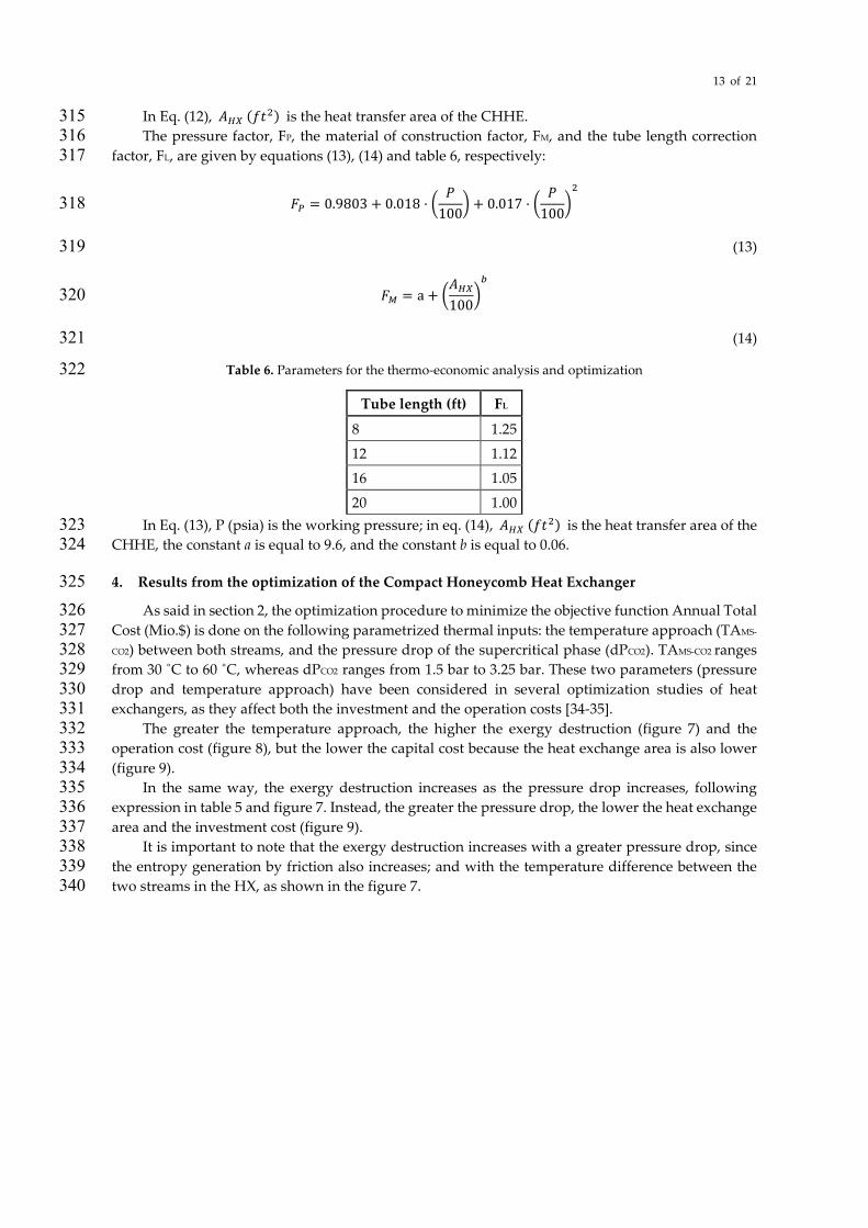
The greater the temperature approach, the higher the exergy destruction (figure 7) and the 332 operation cost (figure 8), but the lower the capital cost because the heat exchange area is also lower 333 (figure 9). 334
In the same way, the exergy destruction increases as the pressure drop increases, following 335 expression in table 5 and figure 7. Instead, the greater the pressure drop, the lower the heat exchange 336 area and the investment cost (figure 9). 337
It is important to note that the exergy destruction increases with a greater pressure drop, since 338 the entropy generation by friction also increases; and with the temperature difference between the 339 two streams in the HX, as shown in the figure 7. 340
14 of 21
341
Figure 7. Exergy destruction in the CHHE, as function of the temperature approach between MS and CO2, and 342 the CO2 pressure drop. 343
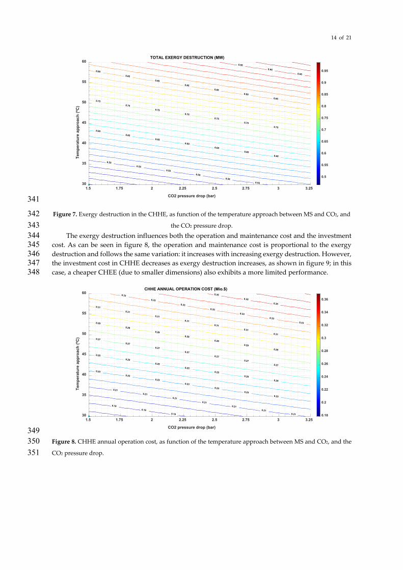
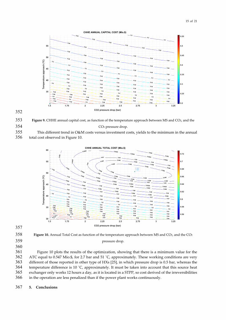
The exergy destruction influences both the operation and maintenance cost and the investment 344 cost. As can be seen in figure 8, the operation and maintenance cost is proportional to the exergy 345 destruction and follows the same variation: it increases with increasing exergy destruction. However, 346 the investment cost in CHHE decreases as exergy destruction increases, as shown in figure 9; in this 347 case, a cheaper CHEE (due to smaller dimensions) also exhibits a more limited performance. 348
349 Figure 8. CHHE annual operation cost, as function of the temperature approach between MS and CO2, and the 350 CO2 pressure drop. 351
1.5 1.75 2 2.25 2.5 2.75 3 3.25
CO2 pressure drop (bar)
30
35
40
45
50
55
60
Tem
pera
ture
app
roac
h (ºC
)
TOTAL EXERGY DESTRUCTION (MW)
0.550.55
0.550.55
0.550.55
0.650.65
0.650.65
0.650.65
0.65
0.750.75
0.750.75
0.750.75
0.75
0.85
0.850.85
0.850.85
0.850.85
0.950.95
0.95
0.5
0.55
0.6
0.65
0.7
0.75
0.8
0.85
0.9
0.95
1.5 1.75 2 2.25 2.5 2.75 3 3.25
CO2 pressure drop (bar)
30
35
40
45
50
55
60
Tem
pera
ture
app
roac
h (ºC
)
CHHE ANNUAL OPERATION COST (Mio.$)
0.190.19
0.19
0.210.21
0.210.21
0.210.21
0.21
0.230.23
0.230.23
0.230.23
0.23
0.250.25
0.250.25
0.250.25
0.25
0.270.27
0.270.27
0.270.27
0.27
0.290.29
0.290.29
0.290.29
0.29
0.310.31
0.310.31
0.310.31
0.31
0.33
0.330.33
0.330.33
0.330.33
0.350.35
0.35
0.18
0.2
0.22
0.24
0.26
0.28
0.3
0.32
0.34
0.36
15 of 21
352
Figure 9. CHHE annual capital cost, as function of the temperature approach between MS and CO2, and the 353 CO2 pressure drop. 354
This different trend in O&M costs versus investment costs, yields to the minimum in the annual 355 total cost observed in Figure 10. 356
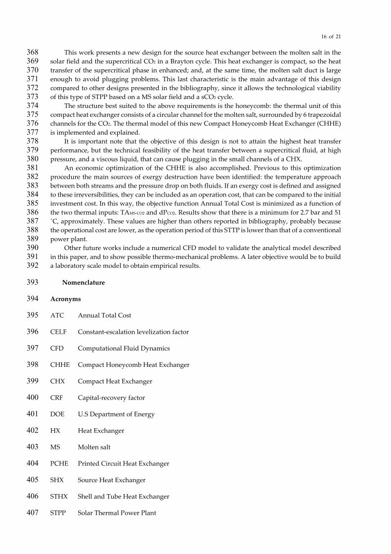
357 Figure 10. Annual Total Cost as function of the temperature approach between MS and CO2, and the CO2 358
pressure drop. 359 360 Figure 10 plots the results of the optimization, showing that there is a minimum value for the 361
ATC equal to 0.547 Mio.$, for 2.7 bar and 51 ˚C, approximately. These working conditions are very 362 different of those reported in other type of HXs [25], in which pressure drop is 0.5 bar, whereas the 363 temperature difference is 10 ˚C, approximately. It must be taken into account that this source heat 364 exchanger only works 12 hours a day, as it is located in a STPP, so cost derived of the irreversibilities 365 in the operation are less penalized than if the power plant works continuously. 366
5. Conclusions 367
1.5 1.75 2 2.25 2.5 2.75 3 3.25
CO2 pressure drop (bar)
35
40
45
50
55Te
mpe
ratu
re a
ppro
ach
(ºC)
CHHE ANNUAL CAPITAL COST (Mio.$)
0.2
0.2
0.2
0.22
0.22
0.22
0.22
0.22
0.22
0.24
0.24
0.24
0.24
0.24
0.24
0.24
0.260.26
0.26
0.26
0.26
0.26
0.26
0.280.28
0.28
0.28
0.28
0.28
0.28
0.30.3
0.30.3
0.3
0.3
0.3
0.3
0.320.32
0.320.32
0.32
0.32
0.32
0.340.34
0.340.34
0.34
0.34
0.34
0.360.36
0.360.36
0.36
0.36
0.36
0.380.38
0.380.38
0.38
0.38
0.38
0.40.4
0.40.4
0.4
0.4
0.4
0.4
0.420.42
0.420.42
0.42
0.42
0.42
0.440.44
0.44
0.44
0.44
0.44
0.46
0.46
0.46
0.46
0.46
0.48
0.48
0.48
0.48
0.5
0.5
0.5
0.52
0.520.54
0.2
0.25
0.3
0.35
0.4
0.45
0.5
0.55
1.5 1.75 2 2.25 2.5 2.75 3 3.25
CO2 pressure drop (bar)
30
35
40
45
50
55
60
Tem
pera
ture
app
roac
h (ºC
)
CHHE ANNUAL TOTAL COST (Mio.$)
0.5480.548
0.548
0.548 0.5480.548
0.548
0.548
0.5490.5490.549
0.549
0.549
0.549 0.5490.549
0.549
0.549
0.550.550.55
0.55
0.55
0.55
0.55 0.550.55
0.55
0.55
0.55250.5525
0.5525
0.5525
0.5525
0.5525
0.55
25
0.5525 0.55250.5525
0.5525
0.5525
0.5550.555
0.555
0.555
0.555
0.555
0.555
0.55
5
0.555
0.555
0.560.56
0.560.56
0.56
0.56
0.56
0.56
0.5650.565
0.5650.565
0.565
0.565
0.565
0.570.57
0.570.57
0.57
0.57
0.57
0.580.58
0.580.58
0.58
0.58
0.58
0.590.59
0.590.59
0.59
0.59
0.59
0.60.6
0.60.6
0.6
0.6
0.6
0.6
0.610.61
0.610.61
0.61
0.61
0.61
0.620.62
0.620.62
0.62
0.62
0.62
0.630.63
0.630.63
0.63
0.63
0.63
0.640.64
0.640.64
0.64
0.64
0.64
0.650.65
0.65
0.65
0.65
0.65
0.66
0.66
0.66
0.66
0.66
0.67
0.67
0.67
0.67
0.68
0.68
0.68
0.69
0.690.7
0.70.710.720.73
0.56
0.58
0.6
0.62
0.64
0.66
0.68
0.7
0.72
X 2.696Y 50.89
16 of 21
This work presents a new design for the source heat exchanger between the molten salt in the 368 solar field and the supercritical CO2 in a Brayton cycle. This heat exchanger is compact, so the heat 369 transfer of the supercritical phase in enhanced; and, at the same time, the molten salt duct is large 370 enough to avoid plugging problems. This last characteristic is the main advantage of this design 371 compared to other designs presented in the bibliography, since it allows the technological viability 372 of this type of STPP based on a MS solar field and a sCO2 cycle. 373
The structure best suited to the above requirements is the honeycomb: the thermal unit of this 374 compact heat exchanger consists of a circular channel for the molten salt, surrounded by 6 trapezoidal 375 channels for the CO2. The thermal model of this new Compact Honeycomb Heat Exchanger (CHHE) 376 is implemented and explained. 377
It is important note that the objective of this design is not to attain the highest heat transfer 378 performance, but the technical feasibility of the heat transfer between a supercritical fluid, at high 379 pressure, and a viscous liquid, that can cause plugging in the small channels of a CHX. 380
An economic optimization of the CHHE is also accomplished. Previous to this optimization 381 procedure the main sources of exergy destruction have been identified: the temperature approach 382 between both streams and the pressure drop on both fluids. If an exergy cost is defined and assigned 383 to these irreversibilities, they can be included as an operation cost, that can be compared to the initial 384 investment cost. In this way, the objective function Annual Total Cost is minimized as a function of 385 the two thermal inputs: TAMS-CO2 and dPCO2. Results show that there is a minimum for 2.7 bar and 51 386 ˚C, approximately. These values are higher than others reported in bibliography, probably because 387 the operational cost are lower, as the operation period of this STTP is lower than that of a conventional 388 power plant. 389
Other future works include a numerical CFD model to validate the analytical model described 390 in this paper, and to show possible thermo-mechanical problems. A later objective would be to build 391 a laboratory scale model to obtain empirical results. 392
Nomenclature 393
Acronyms 394
ATC Annual Total Cost 395
CELF Constant-escalation levelization factor 396
CFD Computational Fluid Dynamics 397
CHHE Compact Honeycomb Heat Exchanger 398
CHX Compact Heat Exchanger 399
CRF Capital-recovery factor 400
DOE U.S Department of Energy 401
HX Heat Exchanger 402
MS Molten salt 403
PCHE Printed Circuit Heat Exchanger 404
SHX Source Heat Exchanger 405
STHX Shell and Tube Heat Exchanger 406
STPP Solar Thermal Power Plant 407
17 of 21
TES Thermal Energy Storage 408
409
Latin letters 410
A Area (m2) 411
c Specific heat (J/kg/ C) 412
C Cost ($) 413
CC Capital Cost ($) 414
CE Cost per unit of exergy ($/Wh) 415
CB Base cost ($) 416
Dh Hydraulic diameter (m) 417
d Diameter (m) 418
dP Pressure Drop (Pa) 419
�̇�𝐶𝑥𝑥 Exergy (W) 420
f Darcy pressure friction loss factor 421
FP Pressure factor 422
FM Material of construction factor 423
FL Tube length correction factor, 424
hconv Convection heat transfer coefficient (W/m2/ C) 425
ieff Weighted average capital cost 426
k Thermal conductivity (W/m/ C) 427
L Length (m) 428
�̇�𝑚 Mass flow rate (kg/s) 429
N Number of heat exchanger elements 430
n Number of years 431
Nu Nusselt number 432
p Pressure (Pa) 433
Pr Prandtl number 434
�̇�𝑄 Thermal power (W) 435
rn Nominal escalation rate 436
18 of 21
Re Reynolds number 437
T Temperature ( C) 438
TA Temperature Approach ( C) 439
U Overall heat transfer coefficient (W/m2/ C) 440
u Velocity (m/s) 441
V Volume (m3) 442
Y Yearly operation time 443
444
Greek Letters 445
ρ Density (kg/m3) 446
𝜇𝜇 Dynamic viscosity (Pa·s) 447
448
Subscripts 449
ave Average 450
net Net 451
p Pressure 452
th Thermal 453
454
455 Author Contributions: “Conceptualization, M.J.Montes and J.I.Linares; methodology, M.J:Montes.; software, 456 M.J.Montes and J.I.Linares; validation, R.Barbero and B.Moratilla; formal analysis, M.J.Montes; investigation, 457 R.Barbero and B.Moratilla; resources, R.Barbero; data curation, B.Moratilla; writing—original draft preparation, 458 M.J.Montes; writing—review and editing, J.I.Linares; visualization, M.J.Montes; supervision, J.I.Linares; project 459 administration, M.J.Montes; funding acquisition, M.J.Montes. All authors have read and agreed to the published 460 version of the manuscript.” 461 Acknowledgments: This work has been developed in the frame of the ACES2030-CM project, funded by the 462 Regional Research and Development in Technology Programme 2018 (ref. P2018/EMT-4319). 463 Conflicts of Interest: 464 “The authors declare no conflict of interest.” 465 “The funders had no role in the design of the study; in the collection, analyses, or interpretation of data; in the 466 writing of the manuscript, or in the decision to publish the results.” 467 468
19 of 21
References 469
1. Mehos, M., Turchi, C., Vidal, J., Wagner, M., Ma, Z., Ho, C., Kolb, W., Andraka, C., Kruizenga, 470 A., 2017. Concentrating Solar Power Gen3 Demonstration Roadmap (No. NREL/TP--5500-67464, 471 1338899). https://doi.org/10.2172/1338899 472
2. Turchi, C.S., Vidal, J., Bauer, M., 2018. Molten salt power towers operating at 600–650 °C: Salt 473 selection and cost benefits. Solar Energy 164, 38–46. https://doi.org/10.1016/j.solener.2018.01.063 474
3. Ehsan, M.M., Guan, Z., Gurgenci, H., Klimenko, A., 2020. Feasibility of dry cooling in 475 supercritical CO2 power cycle in concentrated solar power application: Review and a case study. 476 Renewable and Sustainable Energy Reviews 132, 110055. 477 https://doi.org/10.1016/j.rser.2020.110055 478
4. Wang, K., He, Y.-L., Zhu, H.-H., 2017. Integration between supercritical CO 2 Brayton cycles and 479 molten salt solar power towers: A review and a comprehensive comparison of different cycle 480 layouts. Applied Energy 195, 819–836. 481 https://doi.org/10.1016/j.apenergy.2017.03.099 482
5. Neises, T., Turchi, C., 2019. Supercritical carbon dioxide power cycle design and configuration 483 optimization to minimize levelized cost of energy of molten salt power towers operating at 650 484 °C. Solar Energy 181, 27–36. https://doi.org/10.1016/j.solener.2019.01.078 485
6. Linares, J.I., Montes, M.J., Cantizano, A., Sánchez, C., 2020. A novel supercritical CO2 486 recompression Brayton power cycle for power tower concentrating solar plants. Applied Energy 487 263, 114644. https://doi.org/10.1016/j.apenergy.2020.114644 488
7. Kakaç, S., Liu, H., Pramuanjaroenkij, A., 2012. Heat Exchangers: Selection, Rating, and Thermal 489 Design, Third Edition. CRC Press, Hoboken. 490
8. Du, B.-C., He, Y.-L., Qiu, Y., Liang, Q., Zhou, Y.-P., 2018. Investigation on heat transfer 491 characteristics of molten salt in a shell-and-tube heat exchanger. International Communications 492 in Heat and Mass Transfer 96, 61–68. https://doi.org/10.1016/j.icheatmasstransfer.2018.05.020 493
9. Rajeh, T., Tu, P., Lin, H., Zhang, H., 2018. Thermo-Fluid Characteristics of High Temperature 494 Molten Salt Flowing in Single-Leaf Type Hollow Paddles. Entropy 20, 581. 495 https://doi.org/10.3390/e20080581 496
10. Le Pierres, R, Southall, D., & Osborne S. (2011) Impact of Mechanical Design Issues on Printed 497 Circuit Heat Exchangers. Proceedings of SCO2 Power Cycle Symposium, University of Colorado 498 at Boulder - University Memorial Center, CO 499
11. Southall, D., Le Pierres, R., & Dewson, S. J. (2008). Design considerations for compact heat 500 exchangers. International Congress on Advances in Nuclear Power Plants, American Nuclear 501 Society. ICAPP’08 proceedings of the 2008 International congress on advances in nuclear power 502 plants, California. 503
12. International Project on Innovative Nuclear Reactors and Fuel Cycles, International Atomic 504 Energy Agency, 2013. Challenges related to the use of liquid metal and molten salt coolants in 505 advanced reactors: report of the Collaborative Project COOL of the International Project on 506 Innovative Nuclear Reactors and Fuel Cycles (INPRO). 507
20 of 21
13. Iverson, B.D., Conboy, T.M., Pasch, J.J., Kruizenga, A.M., 2013. Supercritical CO2 Brayton cycles 508 for solar-thermal energy. Applied Energy 111, 957–970. 509 https://doi.org/10.1016/j.apenergy.2013.06.020 510
14. Fu, Q., Ding, J., Lao, J., Wang, W., Lu, J., 2019a. Thermal-hydraulic performance of printed circuit 511 heat exchanger with supercritical carbon dioxide airfoil fin passage and molten salt straight 512 passage. Applied Energy 247, 594–604. https://doi.org/10.1016/j.apenergy.2019.04.049 513
15. Fu, Q., Ding, J., Lao, J., Wang, W., Lu, J., 2019b. Thermal-hydraulic performance of printed circuit 514 heat exchanger with supercritical carbon dioxide airfoil fin passage and molten salt straight 515 passage. Applied Energy 247, 594–604. https://doi.org/10.1016/j.apenergy.2019.04.049 516
16. Shi, H.-Y., Li, M.-J., Wang, W.-Q., Qiu, Y., Tao, W.-Q., 2020. Heat transfer and friction of molten 517 salt and supercritical CO2 flowing in an airfoil channel of a printed circuit heat exchanger. 518 International Journal of Heat and Mass Transfer 150, 119006. 519 https://doi.org/10.1016/j.ijheatmasstransfer.2019.119006 520
17. Sun, X., Zhang, X., Christensen, R., Anderson, M., 2018. Compact Heat Exchanger Design and 521 Testing for Advanced Reactors and Advanced Power Cycles (No. 13–5101, 1437159). 522 https://doi.org/10.2172/1437159 523
18. Hesselgreaves, J.E., 2017. Compact heat exchangers: selection, design, and operation, Second 524 edition. ed. Elsevier/BH, Amsterdam. 525
19. NIST database https://webbook.nist.gov/chemistry/ 526 20. Turchi, C.S., Vidal, J., Bauer, M., 2018. Molten salt power towers operating at 527
600–650 °C: Salt selection and cost benefits. Solar Energy 164, 38–46. 528 https://doi.org/10.1016/j.solener.2018.01.063 529
21. Sun, H., Wang, J., Li, Z., Zhang, P., Su, X., 2018. Corrosion behavior of 316SS and Ni-based alloys 530 in a ternary NaCl-KCl-MgCl2 molten salt. Solar Energy 171, 320–329. 531 https://doi.org/10.1016/j.solener.2018.06.094 532
22. Haynes International https://www.haynesintl.com/ 533 23. ASME Boiler and Pressure Vessel Committee, American Society of Mechanical Engineers, ASME 534
Boiler and Pressure Vessel Committee, Subcommittee on Pressure Vessels, 2010. Rules for 535 construction of pressure vessels. an international code VIII, Division 1 VIII, Division 1. American 536 Society of Mechanical Engineers, New York, N.Y. 537
24. Pacheco, J.E., Ralph, M.E., Chavez, J.M., Dunkin, S.R., Rush, E.E., Ghanbari, C.M., Matthews, 538 M.W., 1995. Results of molten salt panel and component experiments for solar central receivers: 539 Cold fill, freeze/thaw, thermal cycling and shock, and instrumentation tests (No. SAND--94-540 2525, 46671). https://doi.org/10.2172/46671 541
25. Medrano, M., Puente, D., Arenaza, E., Herrazti, B., Paule, A., Brañas, B., Orden, A., Domínguez, 542 M., Stainsby, R., Maisonnier, D., Sardain, P., 2007. Power conversion cycles study for He-cooled 543 reactor concepts for DEMO. Fusion Engineering and Design 82, 2689–2695. 544 https://doi.org/10.1016/j.fusengdes.2007.04.041 545
546 26. Ariu, V. (2014). Heat exchanger analysis for innovative molten salt fast reactor. Master Thesis. 547
ETH Zürich – EPF Lausanne 548
21 of 21
27. Gnielinski, V., 1976. New equations for heat and mass transfer in turbulent pipe and channel 549 flow. International Chemical Engineering 16(2), 359-368. 550
28. Özçelik, Y., 2007. Exergetic optimization of shell and tube heat exchangers using a genetic based 551 algorithm. Applied Thermal Engineering 27, 1849–1856. 552 https://doi.org/10.1016/j.applthermaleng.2007.01.007 553
29. Ashrafizadeh, S.A., 2019. Application of Second Law Analysis in Heat Exchanger Systems. 554 Entropy 21, 606. https://doi.org/10.3390/e21060606 555
30. Bejan, A., 2002. Fundamentals of exergy analysis, entropy generation minimization, and the 556 generation of flow architecture. Int. J. Energy Res. 26, 0–43. https://doi.org/10.1002/er.804 557
31. London, A.L., Shah, R.K., 1983. Costs of Irreversibilities in Heat Exchanger Design. Heat Transfer 558 Engineering 4, 59–73. https://doi.org/10.1080/01457638108939603 559
32. Shah, R.K., Sekulić, D.P., 2003. Fundamentals of heat exchanger design. John Wiley & Sons, 560 Hoboken, NJ. 561
33. Seider, W.D., Seader, J.D., Lewin, D.R., 2004. Product and process design principles: synthesis, 562 analysis, and evaluation, 2. ed. ed. Wiley, New York. 563
34. Kim, E.S., Oh, C.H., Sherman, S., 2008. Simplified optimum sizing and cost analysis for compact 564 heat exchanger in VHTR. Nuclear Engineering and Design 238, 2635–2647. 565 https://doi.org/10.1016/j.nucengdes.2008.05.012 566 35. Yoon, S.-J., Sabharwall, P., Kim, E.-S., 2014. Numerical study on crossflow printed circuit heat 567 exchanger for advanced small modular reactors. International Journal of Heat and Mass Transfer 568 70, 250–263. https://doi.org/10.1016/j.ijheatmasstransfer.2013.10.079 569 570 571