Embed Size (px)
Citation preview
i
ADDIS ABABA UNIVERSITY
ADDIS ABABA INSTITUTE OF TECHNOLOGY
SCHOOL OF MECHANICAL & INDUSTRIAL ENGINEERING
Optimization and Fatigue Analysis of Crane Hook Using
Finite Element Method
A Thesis Submitted for the Partial Fulfilment of Degree of Masters of
Science in Mechanical Engineering (Design)
By:
Shumuye Tigabey
Advisor
Dr. Ing. Tamrat Tesfaye
Co Advisor
Hailemariam Nugus (PhD Candidate)
June 2018
Addis Ababa, Ethiopia

i
Acknowledgement
I would like to thank God for giving me endurance for completion of this thesis. I would like
to express my deep sense of gratitude towards my advisor Dr. Ing. Tamrat Tesfaye and my co-
advisor Hailemariam Nugus for their invaluable guidance, encouragements and inspiration
during the path of this work. their continuous interest was a constant source of motivation for
me throughout the work.

ii
Abstract
The failure of crane hook occurs because of the stress induced due to repetitive loading and
unloading conditions. These are the causes of fatigue failure of the crane hook. To minimize
the failure of crane hook, the stress induced in the crane hook is studied and reduced the
maximum stress than existing (trapezoidal) crane hook. By modifying the geometry (cross
section) the stress of the crane hook is reduced comparing with the standard crane hook. In this
study, the cross section has been selected as a basic parameter to optimize the hook design
which carries 4.5-tons load. Because of the stress reduction the fatigue life of the model-3 crane
hook goes to increase (have better life comparing with standard and other models of crane
hook). Here, there are four types of cross-section for crane hook namely model-1, model-2,
Model-3 and trapezoidal (standard). These crane hooks are modelled and analysed using
SOLIDWORK and ANSYS software respectively, and the results of each modified crane hooks
are compared with trapezoidal hook results based on different criteria’s which are maximum
stress, maximum deformation, fatigue life and weight of the hooks. Finally based on the
comparisons of each modified modelling crane hooks with the standard crane hook, model-3
is selected. The fatigue life cycle of model-3 crane hook is increased by 22.78% from the
standard crane hook with the same applied load. The maximum Von-Misses stress and weight
of model-3 crane hook are reduced from trapezoidal (standard) crane hook by 3.461 MPa
(4.133%) and 0.354 Kg (2.49%) respectively, and model-3 crane hook has better results of
safety factor & fatigue life than standard crane hook with the same applied load. Therefore,
model -3 crane hook is considered as optimum results.
Key words: Crane Hook, Finite Element Method, Weight Optimization, Fatigue Analysis
iii
Table of Contents
Acknowledgement ...................................................................................................................... i
Abstract ...................................................................................................................................... ii
List of Figure............................................................................................................................. vi
List of Table ........................................................................................................................... viii
CHAPTER 1 .............................................................................................................................. 1
1. INTRODUCTION .............................................................................................................. 1
1.1. Types of Crane Hooks ................................................................................................. 3
1.1.1. Types of Crane Hooks based on their shape ........................................................ 3
1.1.2. Types of Crane Hooks based on their manufacturing methods ........................... 4
1.2. Statement of Problem .................................................................................................. 7
1.3. Objective ..................................................................................................................... 7
1.3.1. General Objective ................................................................................................ 7
1.3.2. Specific Objective ................................................................................................ 7
1.4. Methodology used for this thesis ................................................................................ 8
1.5. Significance of the Study ............................................................................................ 9
1.6. Scope and Limitation of the study............................................................................... 9
1.7. Organization of the Study ........................................................................................... 9
CHAPTER 2 ............................................................................................................................ 10
2. LITERATURE REVIEW ................................................................................................. 10
2.1. Gap of the Literature ................................................................................................. 19
CHAPTER 3 ............................................................................................................................ 20
3. MATERIALS AND METHODS ..................................................................................... 20
3.1. Materials .................................................................................................................... 20
3.1.1. Dimensions of standard crane hook ................................................................... 20
3.1.2. Material Selection .............................................................................................. 22
3.2. Analysis and optimization Methods of crane hook ................................................... 27
iv
3.2.1. Methods of Modified Geometry 1 (Model -1) ................................................... 29
3.2.2. Methods of Modified Geometry 2 (Model -2) ................................................... 31
3.2.3. Methods of Modified Geometry 3 (Model -3) ................................................... 31
3.3. Analytical Methods in Structural Design of Crane Hook ......................................... 32
3.3.1. Stress analysis for trapezoidal crane hook ......................................................... 33
3.3.2. Stress analysis for model -1 crane hook ............................................................ 36
3.3.3. Stress analysis for model -2 crane hook ............................................................ 39
3.3.4. Stress analysis for model -3 crane hook ............................................................ 41
3.4. Geometrical Modelling and Numerical Analysis Using Ansys ................................ 43
3.4.1. Geometrical Modelling of the Hooks ................................................................ 44
3.4.2. Mesh Generating of the crane hook ................................................................... 45
3.4.3. Load condition of the crane hook ...................................................................... 47
3.5. Fatigue Analysis of Crane Hooks using Finite Element Method .............................. 48
3.5.1. Fatigue Life and Damage estimation of hooks by FEM .................................... 49
3.5.2. Safety factor of crane hooks .............................................................................. 49
CHAPTER 4 ............................................................................................................................ 50
4. RESULT AND DISCUSSION ......................................................................................... 50
4.1. Static Structural Analysis of Crane Hooks ................................................................ 50
4.1.1. Static structural analysis of trapezoidal crane hook ........................................... 50
4.1.2. Static structural analysis of Model 1crane hook ................................................ 50
4.1.3. Static structural analysis of Model 2 crane hook ............................................... 51
4.1.4. Static structural analysis of Model 3 crane hook ............................................... 52
4.2. Stress and Weight Comparison of the modelled crane hooks ................................... 54
4.3. Fatigue Analysis of Crane Hooks ............................................................................. 57
4.3.1. Fatigue Life and Damage estimation of hooks by FEM .................................... 57
4.3.2. Comparison of the crane hooks with total deformation verses fatigue life ....... 59
4.3.3. Fatigue Safety factor of the crane hooks............................................................ 61

v
4.3.4. Fatigue sensitivity of hooks ............................................................................... 63
CHAPTER 5 ............................................................................................................................ 68
5. CONCLUSION, RECOMMENDATION AND FUTURE WORKS .............................. 68
5.1. Conclusion ................................................................................................................. 68
5.2. Recommendation and Future works .......................................................................... 68
REFERENCE ........................................................................................................................... 70
Appendix .................................................................................................................................. 76
vi
List of Figure
Figure 1-1: Crane with all components [4] ................................................................................ 2
Figure 1-2: Single Crane Hooks [] ............................................................................................. 3
Figure 1-3: Double (Ramshorn) Crane Hook [] ......................................................................... 4
Figure 1-4: Laminated crane hook [40] ..................................................................................... 5
Figure 1-5: Methodology chart .................................................................................................. 8
Figure 3-1: dimensions cross sectional view of the standard (trapezoidal cross section crane
hook) [47]................................................................................................................................. 21
Figure 3-2: Comparison of S-N curve for structural steel, AISI 4340 normalized and annealed
steel .......................................................................................................................................... 27
Figure 3-3: cross section of selected iteration (iteration 2) ...................................................... 30
Figure 3-4: cross section of model 2 crane hook ..................................................................... 31
Figure 3-5: Change and reduce the circular cross section at the nose part of the crane hook
and increase inner width of the high stress area (bi) ................................................................ 32
Figure 3-6: curved beam with its cross section to shows that the neutral and centroidal axes
are not coincident. [48] ............................................................................................................ 33
Figure 3-7: Cross section of the High stress concentration area of model-1 crane hook ........ 37
Figure 3-8: high stress concentration area of cross section for model-2 crane hook ............... 39
Figure 3-9: cross section of high concentration area of cross section model 3 crane hook ..... 41
Figure 3-10: The 3D models of different cross sectional hooks which are trapezoidal, Model-
1, Model-2 and Model-3. ......................................................................................................... 45
Figure 3-11: The mesh generating for the different cross section hooks ................................. 46
Figure 3-12: Applied force on the trapezoidal, Model-1, Model-2, and Model-3 cross section
hooks. ....................................................................................................................................... 48
Figure 4-1: Maximum equivalent (Von-Misses) stress of modelled crane hooks by the
maximum applied load ............................................................................................................. 53
Figure 4-2: Maximum Von-Misses stress and weight comparison of the modelled crane
hooks. ....................................................................................................................................... 55
Figure 4-4 The fatigue life estimatted of the hooks by FEM ................................................... 57
Figure 4-5: Estimated Fatigue damage of hooks ..................................................................... 58
Figure 4-6: The graph of total deformation and available life of the crane hooks .................. 60
Figure 4-7: Safety factor contour plot of the crane hooks ....................................................... 61
Figure 4-8: the fatigue safety factor of the modelled crane hooks by applied different loads 63
vii
Figure 4-9: fatigue sensitivity chart of hooks for estimating available life in cycle depending
on the load variation................................................................................................................. 65
Figure 4-10: the difference of fatigue sensitivity for all modelled hooks ................................ 66
viii
List of Table
Table 3-1: The overall dimensions of the trapezoidal (standard) crane hook .......................... 21
Table 3-2: Comparison of the materials based on their mechanical properties [50, 51] ......... 22
Table 3-3: comparison of the values of S-N curve for structural steel, AISI 4340 steel
normalized, AISI 4340 steel annealed and 4130 steel normalized .......................................... 25
Table 3-4: Analysed variables and analysed functions for this model-1 optimization case .... 29
Table 3-5: comparison of three different Iterations to select one of these............................... 30
Table 3-6: analytical analysis results of crane hooks............................................................... 42
Table 3-7: indicated the mesh generating properties (number of elements and nodes) ........... 46
Table 4-1: Comparison of static structural analysis of model 1 crane hook with trapezoidal
crane hook ................................................................................................................................ 51
Table 4-2: Comparison of static structural analysis of model 2 crane hook with trapezoidal
crane hook ................................................................................................................................ 52
Table 4-3: comparison of trapezoidal and model-3 hooks....................................................... 52
Table 4-4: Comparison of hooks depending on maximum stress and weight of the crane
hooks ........................................................................................................................................ 54
Table 4-5: Comparison of minimum fatigue safety factor with applied different (variable)
loads. ........................................................................................................................................ 62
1
CHAPTER 1
1. INTRODUCTION
Material-handling equipment is equipment that relate to the movement, storage, control and
protection of materials, goods and products throughout the process of manufacturing,
distribution, consumption and disposal. Material handling equipment is the mechanical
equipment involved in the complete system. Material handling equipment is generally
separated into four main categories: storage and handling equipment, engineered systems,
industrial trucks, and bulk material handling. [1]
Crane hook is a curved bar and is used for lifting loads in cranes. Crane hook is the component
which is generally used to elevate the heavy load and transfer it from one place to another in
industries, factories and constructional sites. Crane hook is one of the main and important
components of crane basically a hoisting fixture designed to engage a ring or link of a lifting
chain or the pin of a shackle or cable socket and must follow the health and safety guidelines.
[2, 3]
Cranes are classified as weight handling equipment (WHE). They are primarily designed to
perform weight lifting and, with the proper attachment, excavating operations under varied
conditions. A crane is an item of plant intended for raising or lowering a load and moving it
horizontally including the supporting structure of the crane and its foundations. Cranes have
many configurations to accomplish various construction and industrial operations and are
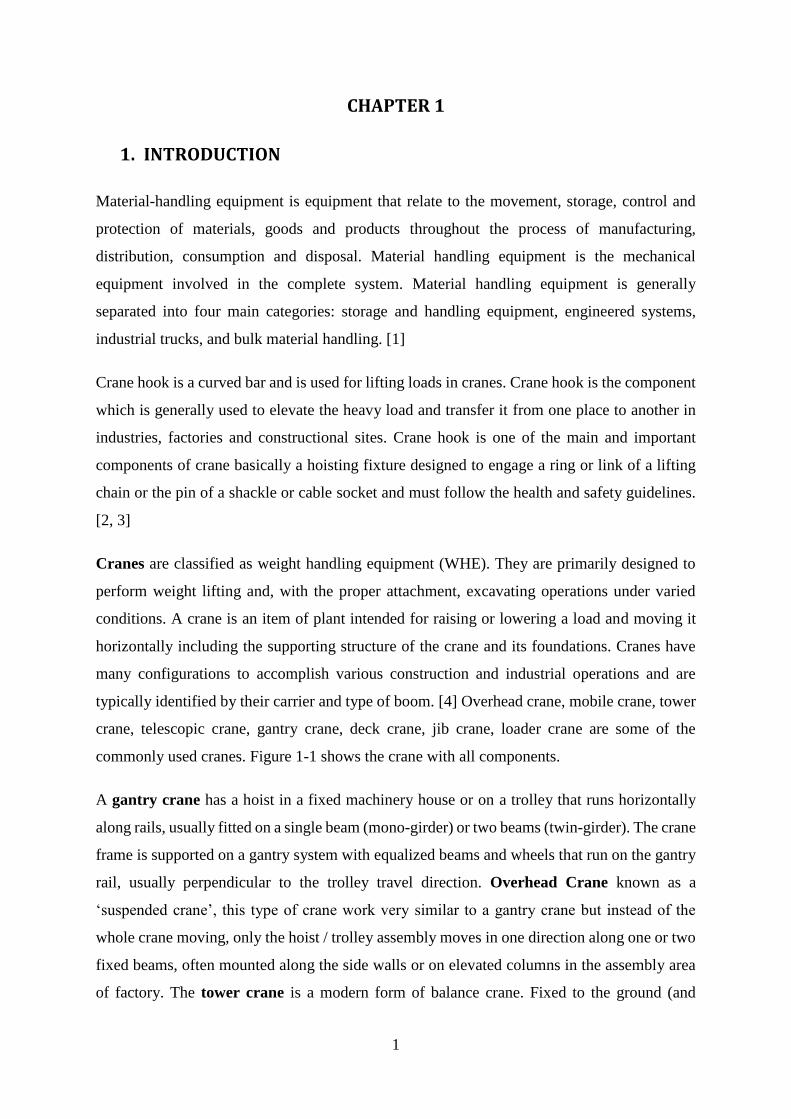
typically identified by their carrier and type of boom. [4] Overhead crane, mobile crane, tower
crane, telescopic crane, gantry crane, deck crane, jib crane, loader crane are some of the
commonly used cranes. Figure 1-1 shows the crane with all components.
A gantry crane has a hoist in a fixed machinery house or on a trolley that runs horizontally
along rails, usually fitted on a single beam (mono-girder) or two beams (twin-girder). The crane
frame is supported on a gantry system with equalized beams and wheels that run on the gantry
rail, usually perpendicular to the trolley travel direction. Overhead Crane known as a
‘suspended crane’, this type of crane work very similar to a gantry crane but instead of the
whole crane moving, only the hoist / trolley assembly moves in one direction along one or two
fixed beams, often mounted along the side walls or on elevated columns in the assembly area
of factory. The tower crane is a modern form of balance crane. Fixed to the ground (and
2
sometimes attached to the sides of structures as well), tower cranes often give the best
combination of height and lifting capacity and are used in the construction of tall buildings. A
mobile crane is a crane capable of travelling over a supporting surface without the need for
fixed runways and relying only on gravity for stability. A loader crane (also called a knuckle-
boom crane or articulating crane) is a hydraulically-powered articulated arm fitted to a truck or
trailer, and is used for loading/unloading the vehicle. A jib crane is a type of crane where a
horizontal member (jib or boom), supporting a moveable hoist, is fixed to a wall or to a floor-
mounted pillar. Jib cranes are used in industrial premises and on military vehicles. Deck Crane
is Located on the ships and boats, these are used for cargo operations or boat unloading and
retrieval where no shore unloading facilities are available. A telescopic crane has a boom that
consists of a number of tubes fitted one inside the other. A hydraulic or other powered
mechanism extends or retracts the tubes to increase or decrease the total length of the boom.
[5]
Figure 1-1: Crane with all components [4]
3
1.1. Types of Crane Hooks
Crane hooks are classified depending on their manufacturing materials as well as the intended
usage and, (amongst other factors) according to this, some aspects are more important than
others. Different types of crane hooks can be classified according to their shapes, method of
manufacture, mode of operation or other unique characteristics. They are made in a variety of
styles to meet specific needs and they are rated for loads of specific type and size.
1.1.1. Types of Crane Hooks based on their shape
There are two types of crane hook depending on their shape which are single crane hook and
double crane hook. As the name suggests, the main difference between these two options is the
number of hooks included, and there are different sub-types possible such as the C-hooks
(which is essentially a single hook variant with a slightly different shape). Figure 1-2 and figure
1-3 shows the single and double crane hooks.
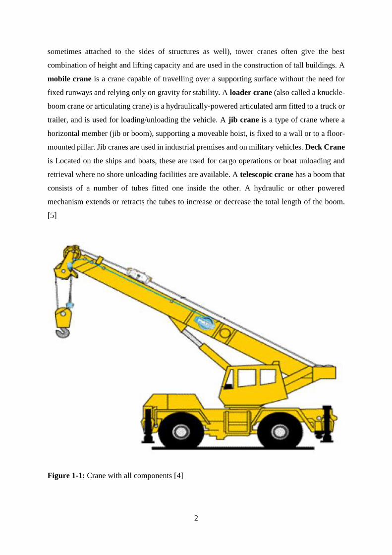
Single Crane Hooks are the right choice if the machinery deals with loads of up to 75 tons;
this lifting hook is very simple and easy to use.
Figure 1-2: Single Crane Hooks []
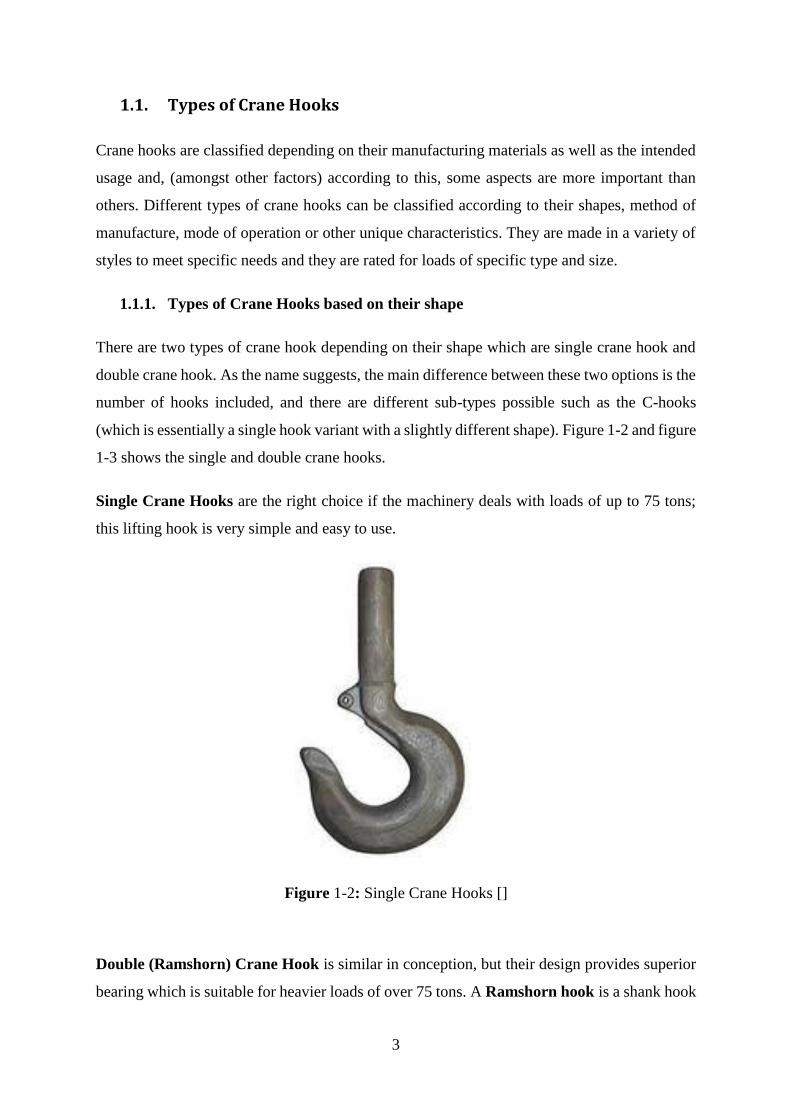
Double (Ramshorn) Crane Hook is similar in conception, but their design provides superior
bearing which is suitable for heavier loads of over 75 tons. A Ramshorn hook is a shank hook
4
with two throat openings, sometimes called sister hooks or twin hooks. Commonly they are
used in applications with shipyard cranes and container cranes. There are two types of
Ramshorn hooks: The Ramshorn Form A hook, which has a solid lower hook design and
the Ramshorn Form B hook which have hole at the lower hook design. The hole of hook is
used to attach rigging.
Figure 1-3: Double (Ramshorn) Crane Hook []
1.1.2. Types of Crane Hooks based on their manufacturing methods
When it comes to the manufacturing methods used to create crane hooks, there are two main
manufacturing types available which are forging crane hooks and laminated crane hooks.
Forging Crane Hooks are forged from a single piece of high quality steel with low carbon
which is cooled slowly to ensure optimum stress resistance. These hooks typically feature very
simple manufacturing and are also very simple to use, since they’re made of a single piece.
5
Forging is defined as a metal working process in which the useful shape of work piece is
obtained in solid state by compressive forces applied through the use of dies and tools.
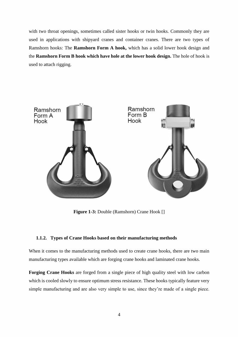
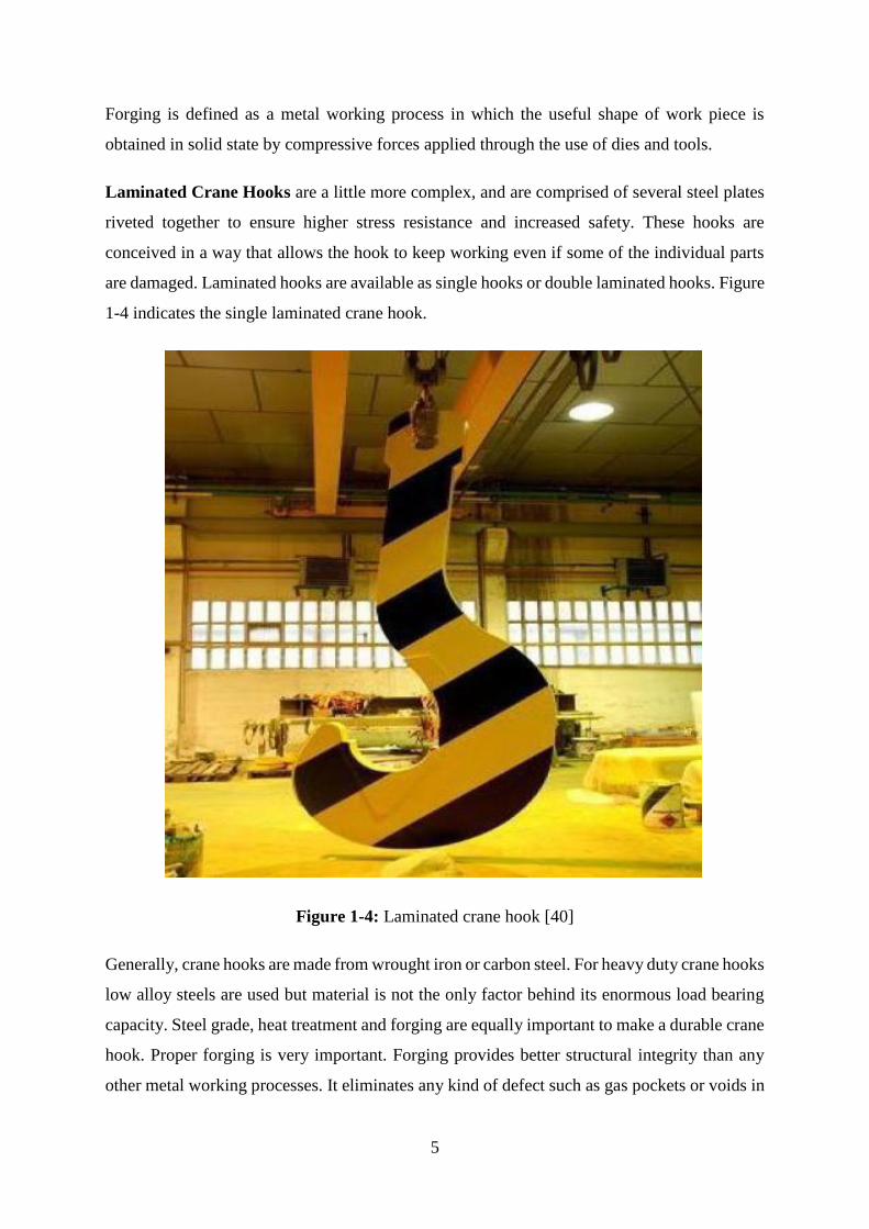
Laminated Crane Hooks are a little more complex, and are comprised of several steel plates
riveted together to ensure higher stress resistance and increased safety. These hooks are
conceived in a way that allows the hook to keep working even if some of the individual parts
are damaged. Laminated hooks are available as single hooks or double laminated hooks. Figure
1-4 indicates the single laminated crane hook.
Figure 1-4: Laminated crane hook [40]
Generally, crane hooks are made from wrought iron or carbon steel. For heavy duty crane hooks
low alloy steels are used but material is not the only factor behind its enormous load bearing
capacity. Steel grade, heat treatment and forging are equally important to make a durable crane
hook. Proper forging is very important. Forging provides better structural integrity than any
other metal working processes. It eliminates any kind of defect such as gas pockets or voids in
6
the hook which can affect its long term performance; thus increasing its strength, toughness,
load bearing capacity and fatigue resistance.
Carbon steel is a popular material for production of crane hook. It is available in numerous
grades, and can be heat-treated to improve its strength, ductility, and machinability. There are
four main grades of carbon steel: low carbon steel, medium carbon steel, high carbon steel and
very high carbon steel. Depending on the amount of carbon present in the material, carbon steel
forgings are hardenable by heat treatment to increase yield and impact strength as well as wear
resistance. Material cost of carbon steel forging is relatively much lower than other steel
forgings, especially compared with stainless steel forging.
The load is usually handlled by means of chain or rope slings attached to hook. Ther are two
most popular design hooks which are standard (single) and ramshorn (double) hooks. Standard
and ramshorn hooks may be flat-die or close die forged or else made of a series of sharped
plates. One piece forged hook is used to lifting loads up to 100tons. Mostly hooks are forged
from low carbon steel. In the process of production hooks are carrfully anealed after forging
and machining. [6]
Due to continuous working of crane hook nanostructure of crane hook are changes and some
problems like weakening of hook due to wear, tensile stresses and excessive thermal stresses
these are some other reason of failure. Hence continuous working of crane hook may increase
the magnitude of these stresses and eventually result in failure of crane hook. Due to some
design modification all the above mentioned failures may be prevented. [7, 42]
Motivation to Work on Weight Optimization and Fatigue Analysis of Crane Hook
In Mesifin Industrial Engineering (MIE) branch of automotive assembly plant during lifting of
the small vehicles accident is happened because of crane hook failure, and this failure caused
to vehicle damage. This accident is happened by didn’t consider the lifting ability and life
cycles of the crane hook. Therefore, here is interested to the fatigue and stress analysis of crane
hook, and this analysis helps to identify lifting ability and estimate the available life of crane
hook.
7
1.2. Statement of Problem
A crane is subjected to continuous loading and unloading condition. These will cause fatigue
failure of the crane hook and lead to serious accidents. Due to continuous loading cycle the life
(the ability to resist the applied load) of crane hook will reduce. Therefore, the fatigue life and
fatigue damage the crane hook must be analysed (estimated).
To reduce the failure of crane hook, the stress induced in the hook must be analysed and
reduced the stress as much as possible with having better other results. Actually, the analysis
of optimized hook stress is reduced compared to the standard hook by means of increasing the
contact area (high stress concentration area of cross section) and by design concept this means
indirectly strength improving of crane hook. By modifying the cross-section stress and weight
of the crane hook can reduce with comparing the standard crane hook, And the fatigue life also
be better than the standard crane hook.
1.3. Objective
1.3.1. General Objective
The general objective of this study is to optimize and fatigue analysis of crane hook using
finite element method
1.3.2. Specific Objective
The specific objective of this study is to:
✓ Reduce stress induced on the high stress concentration area of crane hook
✓ Get have better fatigue life than standard crane hook
✓ Compare the optimized and trapezoidal (standard) crane hooks with respect to
deformation, stress and minimum available life
8
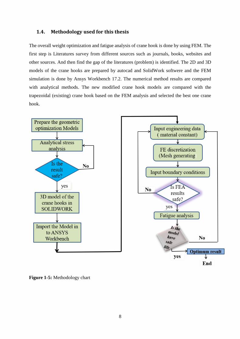
1.4. Methodology used for this thesis
The overall weight optimization and fatigue analysis of crane hook is done by using FEM. The
first step is Literatures survey from different sources such as journals, books, websites and
other sources. And then find the gap of the literatures (problem) is identified. The 2D and 3D
models of the crane hooks are prepared by autocad and SolidWork softwere and the FEM
simulation is done by Ansys Workbench 17.2. The numerical method results are compared
with analytical methods. The new modified crane hook models are compared with the
trapezoidal (existing) crane hook based on the FEM analysis and selected the best one crane
hook.
Figure 1-5: Methodology chart
9
1.5. Significance of the Study
The importance of this study is to reduce the weight of the crane hook which means to make
light weight of crane hook as well as to save the waste of material for Manufacturer Company.
The weight reduction of crane hook is indirectly making light to the overall weight of crane.
This helps to save (reduce) fuel consumption of the crane. The manufacturer company
produced the crane hooks by mass; therefore, it will save more materials and it is good saving
in terms of cost. The other important of this study is to reduce the maximum stress induced on
the crane hook (make having better fatigue life than the existing crane hook). The fatigue life
is checked by analysis fatigue sensitivity of the crane hooks and this analysis helps to estimate
the fatigue life with the applied over load. If the maximum stress is reduced the durability of
the crane hook will improve.
1.6. Scope and Limitation of the study
This study is focus on stress and weight optimization of crane hook by modified its cross
section. And also fatigue analysis of crane hook using FEM is concerned. Then compare the
modified and standard crane hooks based on their results. Other optimization and analysis
methods are not considered in this study.
1.7. Organization of the Study
This thesis is divided in to five chapters. Chapter one is an introduction to the report. It
comprises the background, statement of the problem, objective of the research, organization,
methodology, scope & limitation of the study and the significance of the study are introduced.
Chapter two includes the devoted to theoretical and empirical literatures. Discussed historical
background of crane hook, the methods of previous thesis, journals and books related to studies
of crane hook. Chapter three, structural design part of the thesis, materials and methods are
also developed of the study that fundamental to achieve of the specific objectives of the thesis.
And also included the analysis part (i.e. the heart of the study). The descriptions and steps of
how to finite element analysis of any object using ANSYS. The fourth chapter is about result
and discussion of the study. Compare the results of each modified models of crane hooks with
trapezoidal (standard) crane hook. The last chapter of this study is included the conclusions,
recommendations and future works.
10
CHAPTER 2
2. LITERATURE REVIEW
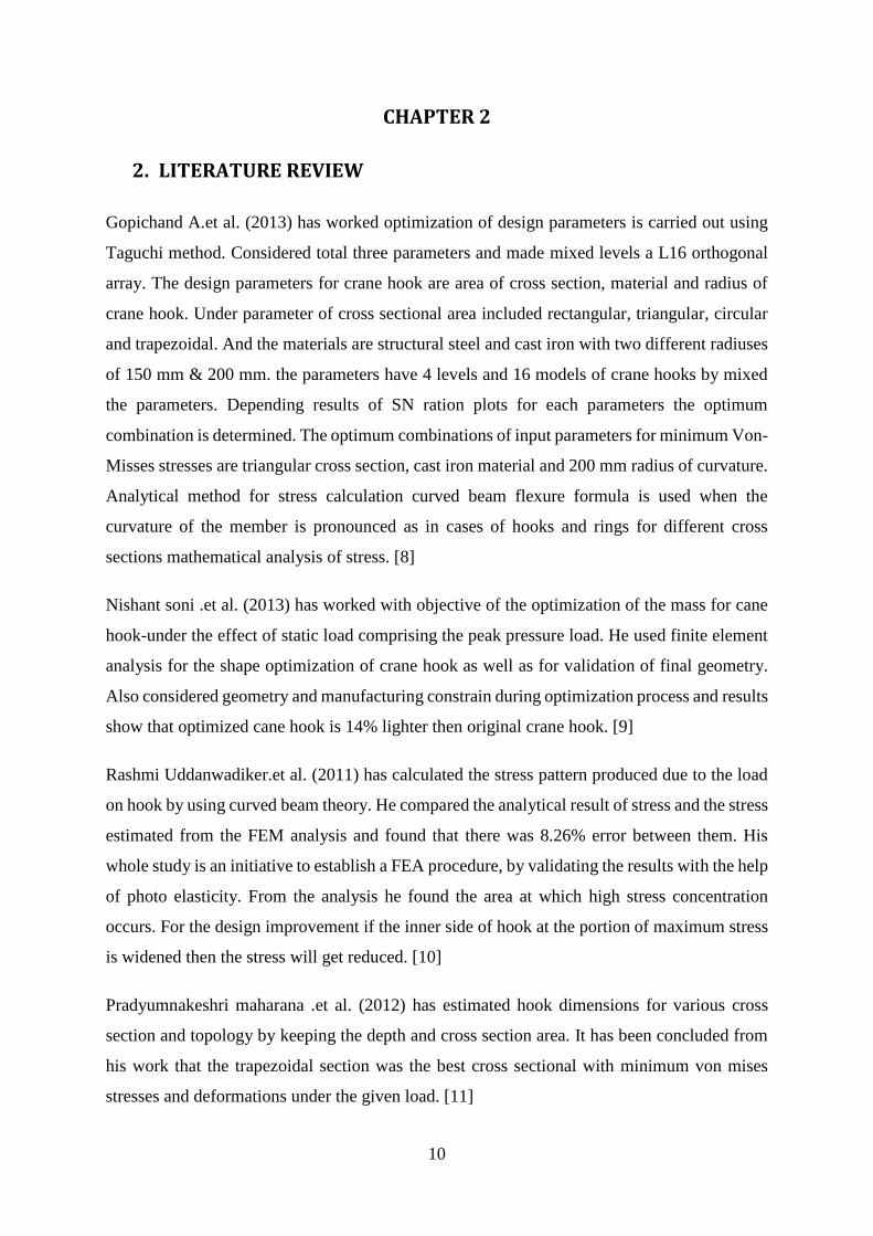
Gopichand A.et al. (2013) has worked optimization of design parameters is carried out using
Taguchi method. Considered total three parameters and made mixed levels a L16 orthogonal
array. The design parameters for crane hook are area of cross section, material and radius of
crane hook. Under parameter of cross sectional area included rectangular, triangular, circular
and trapezoidal. And the materials are structural steel and cast iron with two different radiuses
of 150 mm & 200 mm. the parameters have 4 levels and 16 models of crane hooks by mixed
the parameters. Depending results of SN ration plots for each parameters the optimum
combination is determined. The optimum combinations of input parameters for minimum Von-
Misses stresses are triangular cross section, cast iron material and 200 mm radius of curvature.
Analytical method for stress calculation curved beam flexure formula is used when the
curvature of the member is pronounced as in cases of hooks and rings for different cross
sections mathematical analysis of stress. [8]
Nishant soni .et al. (2013) has worked with objective of the optimization of the mass for cane
hook-under the effect of static load comprising the peak pressure load. He used finite element
analysis for the shape optimization of crane hook as well as for validation of final geometry.
Also considered geometry and manufacturing constrain during optimization process and results
show that optimized cane hook is 14% lighter then original crane hook. [9]
Rashmi Uddanwadiker.et al. (2011) has calculated the stress pattern produced due to the load
on hook by using curved beam theory. He compared the analytical result of stress and the stress
estimated from the FEM analysis and found that there was 8.26% error between them. His
whole study is an initiative to establish a FEA procedure, by validating the results with the help
of photo elasticity. From the analysis he found the area at which high stress concentration
occurs. For the design improvement if the inner side of hook at the portion of maximum stress
is widened then the stress will get reduced. [10]
Pradyumnakeshri maharana .et al. (2012) has estimated hook dimensions for various cross
section and topology by keeping the depth and cross section area. It has been concluded from
his work that the trapezoidal section was the best cross sectional with minimum von mises
stresses and deformations under the given load. [11]
11
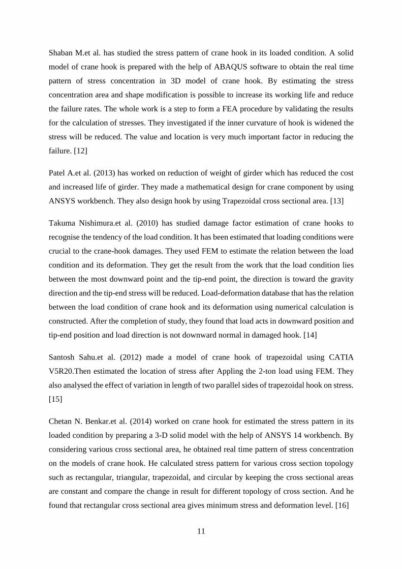
Shaban M.et al. has studied the stress pattern of crane hook in its loaded condition. A solid
model of crane hook is prepared with the help of ABAQUS software to obtain the real time
pattern of stress concentration in 3D model of crane hook. By estimating the stress
concentration area and shape modification is possible to increase its working life and reduce
the failure rates. The whole work is a step to form a FEA procedure by validating the results
for the calculation of stresses. They investigated if the inner curvature of hook is widened the
stress will be reduced. The value and location is very much important factor in reducing the
failure. [12]
Patel A.et al. (2013) has worked on reduction of weight of girder which has reduced the cost
and increased life of girder. They made a mathematical design for crane component by using
ANSYS workbench. They also design hook by using Trapezoidal cross sectional area. [13]
Takuma Nishimura.et al. (2010) has studied damage factor estimation of crane hooks to
recognise the tendency of the load condition. It has been estimated that loading conditions were
crucial to the crane-hook damages. They used FEM to estimate the relation between the load
condition and its deformation. They get the result from the work that the load condition lies
between the most downward point and the tip-end point, the direction is toward the gravity
direction and the tip-end stress will be reduced. Load-deformation database that has the relation
between the load condition of crane hook and its deformation using numerical calculation is
constructed. After the completion of study, they found that load acts in downward position and
tip-end position and load direction is not downward normal in damaged hook. [14]
Santosh Sahu.et al. (2012) made a model of crane hook of trapezoidal using CATIA
V5R20.Then estimated the location of stress after Appling the 2-ton load using FEM. They
also analysed the effect of variation in length of two parallel sides of trapezoidal hook on stress.
[15]
Chetan N. Benkar.et al. (2014) worked on crane hook for estimated the stress pattern in its
loaded condition by preparing a 3-D solid model with the help of ANSYS 14 workbench. By
considering various cross sectional area, he obtained real time pattern of stress concentration
on the models of crane hook. He calculated stress pattern for various cross section topology
such as rectangular, triangular, trapezoidal, and circular by keeping the cross sectional areas
are constant and compare the change in result for different topology of cross section. And he
found that rectangular cross sectional area gives minimum stress and deformation level. [16]
12
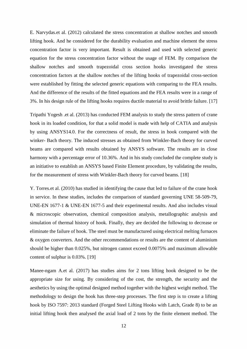
E. Narvydas.et al. (2012) calculated the stress concentration at shallow notches and smooth
lifting hook. And he considered for the durability evaluation and machine element the stress
concentration factor is very important. Result is obtained and used with selected generic
equation for the stress concentration factor without the usage of FEM. By comparison the
shallow notches and smooth trapezoidal cross section hooks investigated the stress
concentration factors at the shallow notches of the lifting hooks of trapezoidal cross-section
were established by fitting the selected generic equations with comparing to the FEA results.
And the difference of the results of the fitted equations and the FEA results were in a range of
3%. In his design rule of the lifting hooks requires ductile material to avoid brittle failure. [17]
Tripathi Yogesh .et al. (2013) has conducted FEM analysis to study the stress pattern of crane
hook in its loaded condition, for that a solid model is made with help of CATIA and analysis
by using ANSYS14.0. For the correctness of result, the stress in hook compared with the
winker- Bach theory. The induced stresses as obtained from Winkler-Bach theory for curved
beams are compared with results obtained by ANSYS software. The results are in close
harmony with a percentage error of 10.36%. And in his study concluded the complete study is
an initiative to establish an ANSYS based Finite Element procedure, by validating the results,
for the measurement of stress with Winkler-Bach theory for curved beams. [18]
Y. Torres.et al. (2010) has studied in identifying the cause that led to failure of the crane hook
in service. In these studies, includes the comparison of standard governing UNE 58-509-79,
UNE-EN 1677-1 & UNE-EN 1677-5 and their experimental results. And also includes visual
& microscopic observation, chemical composition analysis, metallographic analysis and
simulation of thermal history of hook. Finally, they are decided the following to decrease or
eliminate the failure of hook. The steel must be manufactured using electrical melting furnaces
& oxygen converters. And the other recommendations or results are the content of aluminium
should be higher than 0.025%, but nitrogen cannot exceed 0.0075% and maximum allowable
content of sulphur is 0.03%. [19]
Manee-ngam A.et al. (2017) has studies aims for 2 tons lifting hook designed to be the
appropriate size for using. By considering of the cost, the strength, the security and the
aesthetics by using the optimal designed method together with the highest weight method. The
methodology to design the hook has three-step processes. The first step is to create a lifting
hook by ISO 7597: 2013 standard (Forged Steel Lifting Hooks with Latch, Grade 8) to be an
initial lifting hook then analysed the axial load of 2 tons by the finite element method. The
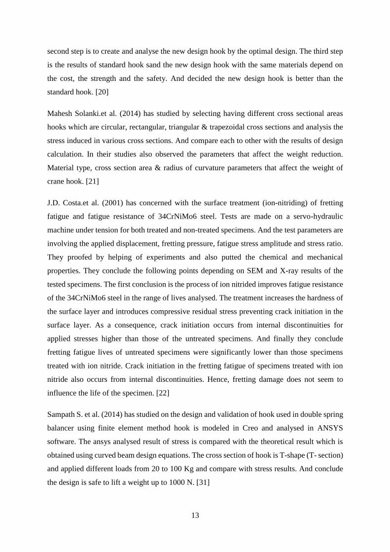
13
second step is to create and analyse the new design hook by the optimal design. The third step
is the results of standard hook sand the new design hook with the same materials depend on
the cost, the strength and the safety. And decided the new design hook is better than the
standard hook. [20]
Mahesh Solanki.et al. (2014) has studied by selecting having different cross sectional areas
hooks which are circular, rectangular, triangular & trapezoidal cross sections and analysis the
stress induced in various cross sections. And compare each to other with the results of design
calculation. In their studies also observed the parameters that affect the weight reduction.
Material type, cross section area & radius of curvature parameters that affect the weight of
crane hook. [21]
J.D. Costa.et al. (2001) has concerned with the surface treatment (ion-nitriding) of fretting
fatigue and fatigue resistance of 34CrNiMo6 steel. Tests are made on a servo-hydraulic
machine under tension for both treated and non-treated specimens. And the test parameters are
involving the applied displacement, fretting pressure, fatigue stress amplitude and stress ratio.
They proofed by helping of experiments and also putted the chemical and mechanical
properties. They conclude the following points depending on SEM and X-ray results of the
tested specimens. The first conclusion is the process of ion nitrided improves fatigue resistance
of the 34CrNiMo6 steel in the range of lives analysed. The treatment increases the hardness of
the surface layer and introduces compressive residual stress preventing crack initiation in the
surface layer. As a consequence, crack initiation occurs from internal discontinuities for
applied stresses higher than those of the untreated specimens. And finally they conclude
fretting fatigue lives of untreated specimens were significantly lower than those specimens
treated with ion nitride. Crack initiation in the fretting fatigue of specimens treated with ion
nitride also occurs from internal discontinuities. Hence, fretting damage does not seem to
influence the life of the specimen. [22]
Sampath S. et al. (2014) has studied on the design and validation of hook used in double spring
balancer using finite element method hook is modeled in Creo and analysed in ANSYS
software. The ansys analysed result of stress is compared with the theoretical result which is
obtained using curved beam design equations. The cross section of hook is T-shape (T- section)
and applied different loads from 20 to 100 Kg and compare with stress results. And conclude
the design is safe to lift a weight up to 1000 N. [31]
14
Prashant R. et al. (2015) has Studied about Structural Analysis and improving performance of
Crane Hook. And also compare the Manufacturing process of crane hook. Forging is preferred
to casting as the crane hooks produced from forging are much stronger than that produced by
casting. The reason been in casting the molten metal when solidifies, it has some residual
stresses due to non-uniform solidification. Thus casted crane hooks cannot bear high tensile
loads. And decide increases the stress slightly though reducing the cost of material. Finally,
discus from the stress analysis it is observed that the cross section of max stress area. If the
area on the inner side of the hook at the portion of max stress is widened, then the stresses will
get reduced. Analytically if the thickness is increased by 3 mm, stresses are reduced by 17%.
Thus the design can be modified by increasing the thickness on the inner curvature so that the
chances of failure are reduced considerably. [32]
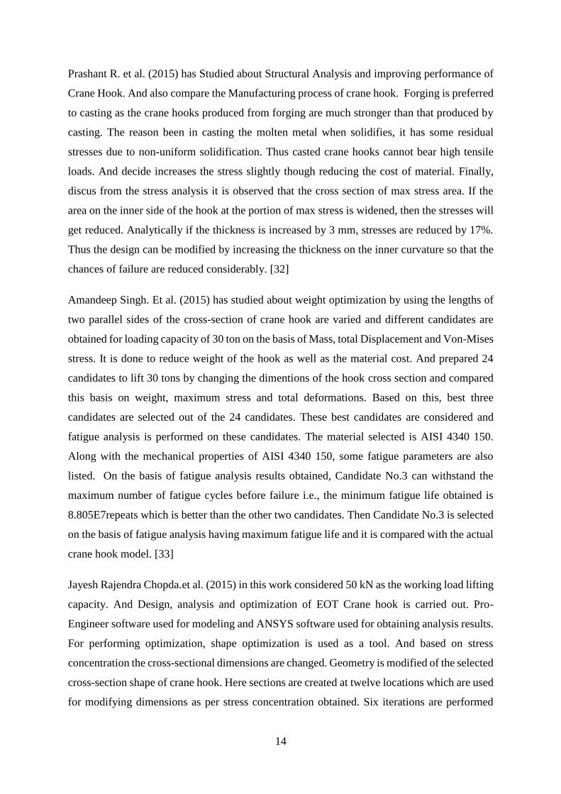
Amandeep Singh. Et al. (2015) has studied about weight optimization by using the lengths of
two parallel sides of the cross-section of crane hook are varied and different candidates are
obtained for loading capacity of 30 ton on the basis of Mass, total Displacement and Von-Mises
stress. It is done to reduce weight of the hook as well as the material cost. And prepared 24
candidates to lift 30 tons by changing the dimentions of the hook cross section and compared
this basis on weight, maximum stress and total deformations. Based on this, best three
candidates are selected out of the 24 candidates. These best candidates are considered and
fatigue analysis is performed on these candidates. The material selected is AISI 4340 150.
Along with the mechanical properties of AISI 4340 150, some fatigue parameters are also
listed. On the basis of fatigue analysis results obtained, Candidate No.3 can withstand the
maximum number of fatigue cycles before failure i.e., the minimum fatigue life obtained is
8.805E7repeats which is better than the other two candidates. Then Candidate No.3 is selected
on the basis of fatigue analysis having maximum fatigue life and it is compared with the actual
crane hook model. [33]
Jayesh Rajendra Chopda.et al. (2015) in this work considered 50 kN as the working load lifting
capacity. And Design, analysis and optimization of EOT Crane hook is carried out. Pro-
Engineer software used for modeling and ANSYS software used for obtaining analysis results.
For performing optimization, shape optimization is used as a tool. And based on stress
concentration the cross-sectional dimensions are changed. Geometry is modified of the selected
cross-section shape of crane hook. Here sections are created at twelve locations which are used
for modifying dimensions as per stress concentration obtained. Six iterations are performed
15
and the iterations are in deferent area of the hook. Then compared with the basic case (standard
hook) and the best optimized iteration is selected which is iteration 6. The iteration 6 is on the
top part (straight part) of the hook. Recommended best optimized cross-section is given for
manufacturing and testing. [34]
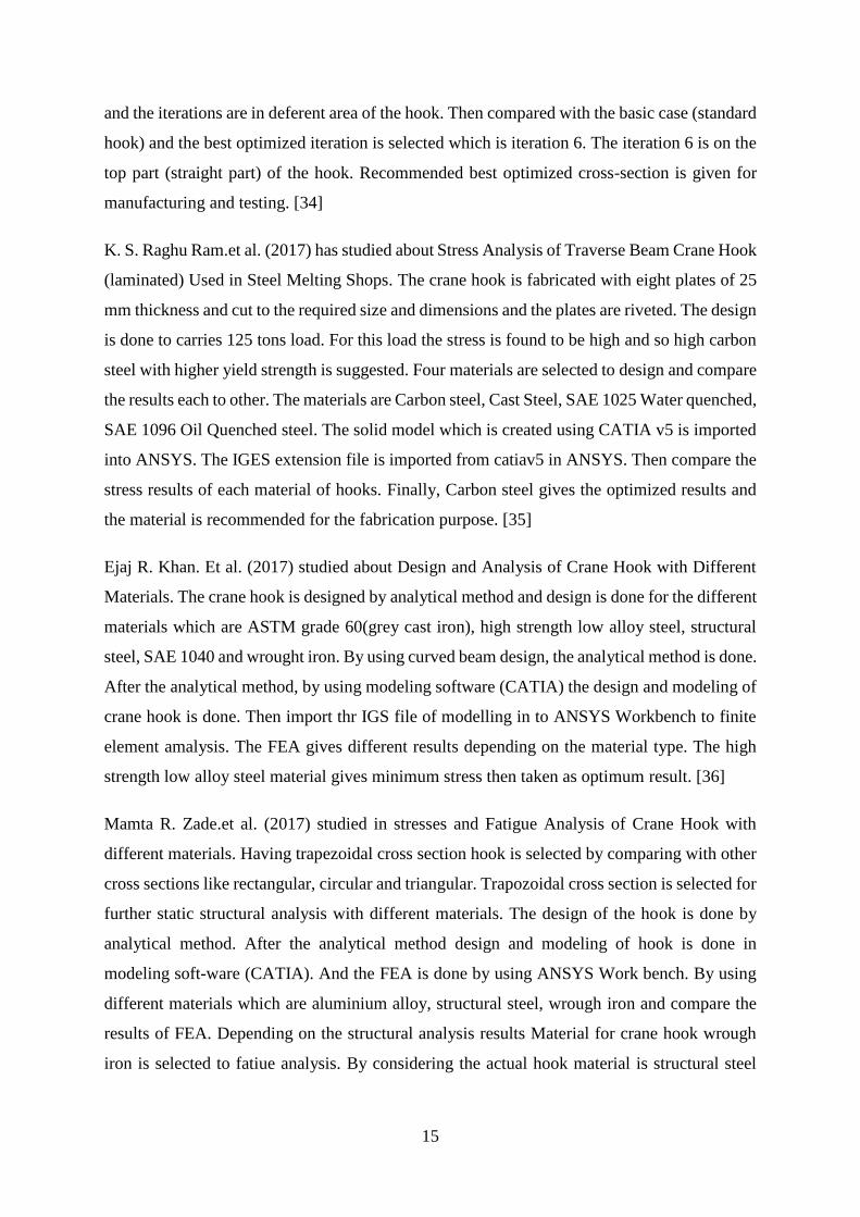
K. S. Raghu Ram.et al. (2017) has studied about Stress Analysis of Traverse Beam Crane Hook
(laminated) Used in Steel Melting Shops. The crane hook is fabricated with eight plates of 25
mm thickness and cut to the required size and dimensions and the plates are riveted. The design
is done to carries 125 tons load. For this load the stress is found to be high and so high carbon
steel with higher yield strength is suggested. Four materials are selected to design and compare
the results each to other. The materials are Carbon steel, Cast Steel, SAE 1025 Water quenched,
SAE 1096 Oil Quenched steel. The solid model which is created using CATIA v5 is imported
into ANSYS. The IGES extension file is imported from catiav5 in ANSYS. Then compare the
stress results of each material of hooks. Finally, Carbon steel gives the optimized results and
the material is recommended for the fabrication purpose. [35]
Ejaj R. Khan. Et al. (2017) studied about Design and Analysis of Crane Hook with Different
Materials. The crane hook is designed by analytical method and design is done for the different
materials which are ASTM grade 60(grey cast iron), high strength low alloy steel, structural
steel, SAE 1040 and wrought iron. By using curved beam design, the analytical method is done.
After the analytical method, by using modeling software (CATIA) the design and modeling of
crane hook is done. Then import thr IGS file of modelling in to ANSYS Workbench to finite
element amalysis. The FEA gives different results depending on the material type. The high
strength low alloy steel material gives minimum stress then taken as optimum result. [36]
Mamta R. Zade.et al. (2017) studied in stresses and Fatigue Analysis of Crane Hook with
different materials. Having trapezoidal cross section hook is selected by comparing with other
cross sections like rectangular, circular and triangular. Trapozoidal cross section is selected for
further static structural analysis with different materials. The design of the hook is done by
analytical method. After the analytical method design and modeling of hook is done in
modeling soft-ware (CATIA). And the FEA is done by using ANSYS Work bench. By using
different materials which are aluminium alloy, structural steel, wrough iron and compare the
results of FEA. Depending on the structural analysis results Material for crane hook wrough
iron is selected to fatiue analysis. By considering the actual hook material is structural steel
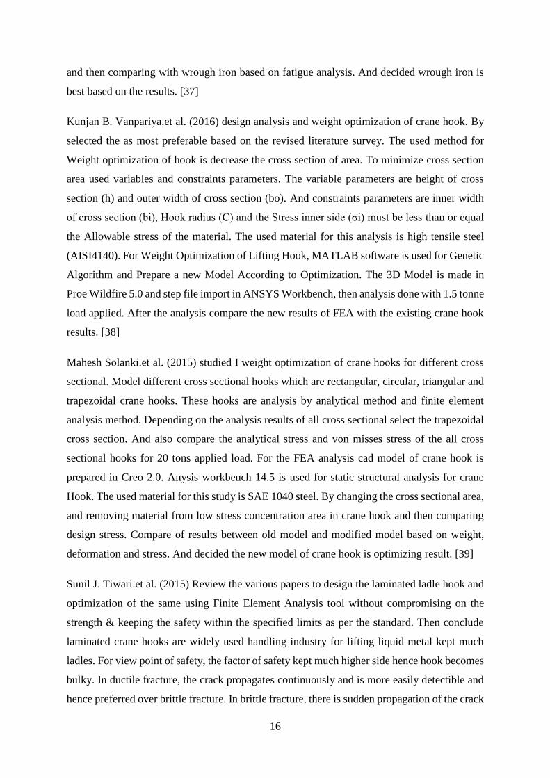
16
and then comparing with wrough iron based on fatigue analysis. And decided wrough iron is
best based on the results. [37]
Kunjan B. Vanpariya.et al. (2016) design analysis and weight optimization of crane hook. By
selected the as most preferable based on the revised literature survey. The used method for
Weight optimization of hook is decrease the cross section of area. To minimize cross section
area used variables and constraints parameters. The variable parameters are height of cross
section (h) and outer width of cross section (bo). And constraints parameters are inner width
of cross section (bi), Hook radius (C) and the Stress inner side (σi) must be less than or equal
the Allowable stress of the material. The used material for this analysis is high tensile steel
(AISI4140). For Weight Optimization of Lifting Hook, MATLAB software is used for Genetic
Algorithm and Prepare a new Model According to Optimization. The 3D Model is made in
Proe Wildfire 5.0 and step file import in ANSYS Workbench, then analysis done with 1.5 tonne
load applied. After the analysis compare the new results of FEA with the existing crane hook
results. [38]
Mahesh Solanki.et al. (2015) studied I weight optimization of crane hooks for different cross
sectional. Model different cross sectional hooks which are rectangular, circular, triangular and
trapezoidal crane hooks. These hooks are analysis by analytical method and finite element
analysis method. Depending on the analysis results of all cross sectional select the trapezoidal
cross section. And also compare the analytical stress and von misses stress of the all cross
sectional hooks for 20 tons applied load. For the FEA analysis cad model of crane hook is
prepared in Creo 2.0. Anysis workbench 14.5 is used for static structural analysis for crane
Hook. The used material for this study is SAE 1040 steel. By changing the cross sectional area,
and removing material from low stress concentration area in crane hook and then comparing
design stress. Compare of results between old model and modified model based on weight,
deformation and stress. And decided the new model of crane hook is optimizing result. [39]
Sunil J. Tiwari.et al. (2015) Review the various papers to design the laminated ladle hook and
optimization of the same using Finite Element Analysis tool without compromising on the
strength & keeping the safety within the specified limits as per the standard. Then conclude
laminated crane hooks are widely used handling industry for lifting liquid metal kept much
ladles. For view point of safety, the factor of safety kept much higher side hence hook becomes
bulky. In ductile fracture, the crack propagates continuously and is more easily detectible and
hence preferred over brittle fracture. In brittle fracture, there is sudden propagation of the crack
17
and hook fails suddenly. This type of fracture is very dangerous as it is difficult to detect. The
finite element method has been evolved as important tool for design an optimization of the
structure. Finally recommended very few article have been published so far regarding stress
analysis and design optimization of laminated crane hook. [40]
Niranjan Desai.et al. (2016) Studied optimize the performance of the crane hook based on
stress, geometry, and weight. A single load is considered and multiple cross sections including
square, circular, and trapezoidal are analyzed. The analysis takes the form of theoretical
calculations and finite element analysis through the use of SOLIDWORKS Simulation. The
results show that for a given cross sectional area, a trapezoid cross section of a hook has better
performance in terms of maximum stress than a circular or square cross section. The parameters
of the trapezoidal cross section are varied to determine the values that provide the optimal
performance. And decided the highest value for h will give the lowest weight. But it is
important to keep the proportions of the hook. A very large value of h will increase the overall
extents of the hook profile and create inefficiencies in packaging. Depending on the results
trapezoidal cross section is selected to check with other materials. The materials considered in
this optimization are A-36 steel, 6061-T6 Aluminium, and Ti-6AL-4V Titanium. The result in
percent decrease of the weight between steel and aluminium or titanium is as large as 80%.
This indicates that in terms of performance, aluminium or titanium a clear choice over steel.
[41]
Omkar P. et al. (2015) have Studies about trapezoidal crane hook design the hook by using
curved beam design theory. The CAD model of a lifting crane hook is initially prepared from
the Analytical Design. The designed trapezoidal section crane hook is modeled using UG-NX
8.0. Then import the CAD model into ANSYS Workbench. By applied the load until 20 tons
estimated the results of FEM analysed. The model of hook is checked by applied loads of 15,
18 and 20 tons. And select three different still materials which are structural steel, AISI 4140
steel and AISI 4340 steel. The von-misses stress developed in the model by FEM method these
results Von-Misses stresses are being compared with Taguchi L9 orthogonal array for specific
results. Suggest about fatigue failure of brittle and ductile materials. And also about other
failures which are Bending stresses combined with tensile stresses, weakening of hook due to
wear, plastic deformation due to overloading, and excessive thermal stresses. And conclude
AISI-4340 for 20-ton load is best suitable material for the manufacturing of the crane hook by
considering the Taguchi results of stress and deflection. [42]
18
Studied on the stress pattern of crane hook in its loaded condition, the stresses are obtained by
using finite element analysis and Winkler-Batch formula method in different cross- sections
are compared. A solid model of crane hook is prepared by using Creo Parametric 2.0 (Computer
Aided Three Dimensional Interactive Application) software. The FEM analysis of stress
distribution in 3D model of crane hook is obtained using ANSYS software. By starting as the
initial point, the material type, cross section area and radius are design parameters that affect
the weight of crane hook. To reduce the stress in the cross section of the hook is done by
changing its design parameters and increased its mass material. In his study prepared three
trapezoidal cross sections having different inner width of the cross section and analysis using
analytical and FEM analysis. Compare the results of each modelled crane hooks with respect
to analytical & FEM stresses, weight and deformation. Finally put in percentage the value of
increased weight and reduced stresses induced on the crane hooks. Then concluded trapezoidal
crane hook cross section 3 is better based on the stress value. But in his study less work has
been done on the optimization of crane hook because the weight is increased from the standard
hook. [43]
This work is to design a crane hook using different materials which are Forged Steel AISI 4140,
Grey cast iron, Carbon Steel ASTM A148, Stainless Steel 316(marine). A 3-D model of the
crane hook was designed based on the sketch using NX-CADD modeling software and analysis
by ANSYS workbench to calculate the total deformation and von mises stress distribution. And
compared with the results of each material modelled crane hooks. The concluded Forged Steel
AISI 4140 and Stainless Steel 316(marine) are more suitable for making crane hooks. [ 44]
Improving the durability of E.O.T. crane stracture and optimize the ramshorn hook material for
improving its solidity by using FEM. The analysis consists of three major components of
E.O.T. crane which are main longitudinal girder, cross girder and ramshorn crane hook. The
analysis of ramshorn crane hook is based on the three different materials are En-22, steel-20
and forged steel. And also the trapezoidal cross sectional ramshorn crane hook is checked with
another two cross sections which are round and rectangular cross sections. After analysis
compared according to the results of Von-Misses stress and total deformation of the trapezoidal
cross section ramshorn crane hooks with different materials. Then decided En-22 material is
most excellent from another two materials and trapezoidal cross section is better than the round
and rectangular cross sections. [45]
19
Studies the Stress Analysis of Ramshorn crane Hook with Different Cross Sections. By only
changing cross sectional shape of the ramshorn crane hook and keep constant material
properties, applied load and area of critical cross section for all selected cross sections. The
selected cross sections are circular, T section and I section. And the effect of cross sectional
shape on stress induced is analysed. The model of Ramshorn hook has been prepared in
SolidWorks. And the FEM stress and total deformation analysis of hook is done using ANSYS
14 workbench. The deflection and von Mises stresses have been compared for all selected cross
sectional shapes of hook. Then concluded Ramshorn hook with I-cross section is best as it
gives minimum stress and deformation value under given load in comparison with other
counterparts. [46]
Studied at experimentally investigating the effects of normalizing, and conventional hardening
on the hardness, microstructure and toughness of AISI 4340 steel. The specimen was machined
to ASTM standards and then different tests like microstructure analysis, hardness test, impact
test, and were carried out after the heat treatment processes. It was found the impact resistance
value of specimen in normalizing is too high compared to conventional hardening specimen.
[52]
the study was focused on investigate the effect of chain installation condition on stress
distribution that could eventually cause disastrous failure from sudden deformation and
geometric rupture. To estimate the effect of different load cases on structural rigidity of the
chain which is used in the crane utilized 3D modelling and finite element analysis. And used
CATIA for modelling and ANSYS for the analysis of the chain. Based on the results of finite
element analysis decided the stress is strongly affected by the condition of the chain installed
in the hook. [53]
2.1. Gap of the Literature
Generally, the literatures stated above studied about the stress on the hooks by using different
methods and about causes to fracture of crane hooks. Compare the trapezoidal cross section
hook with other regular cross sections which are circular, triangular and rectangular cross
sections depending on stress then they decided trapezoidal is best. Some studies are available
about weight reduction of hook by changing the material type and cross sections; but in their
work when the weight is reducing the stress is increase with comparing the trapezoidal
20
(standard) hook. But there is no work about optimization of weight and stress parallelly by
modified the cross section of the crane hook. Which means reducing the weight and stress by
comparing the trapezoidal (standard) crane hook with modified one.
By taking this gap, here the weight and maximum stress modified crane hook are reduced
parallelly with comparing the trapezoidal (standard) crane hook. And also estimated the fatigue
life of the modified crane hook is greater than the trapezoidal (standard) crane hook.
CHAPTER 3
3. MATERIALS AND METHODS
3.1. Materials
3.1.1. Dimensions of standard crane hook
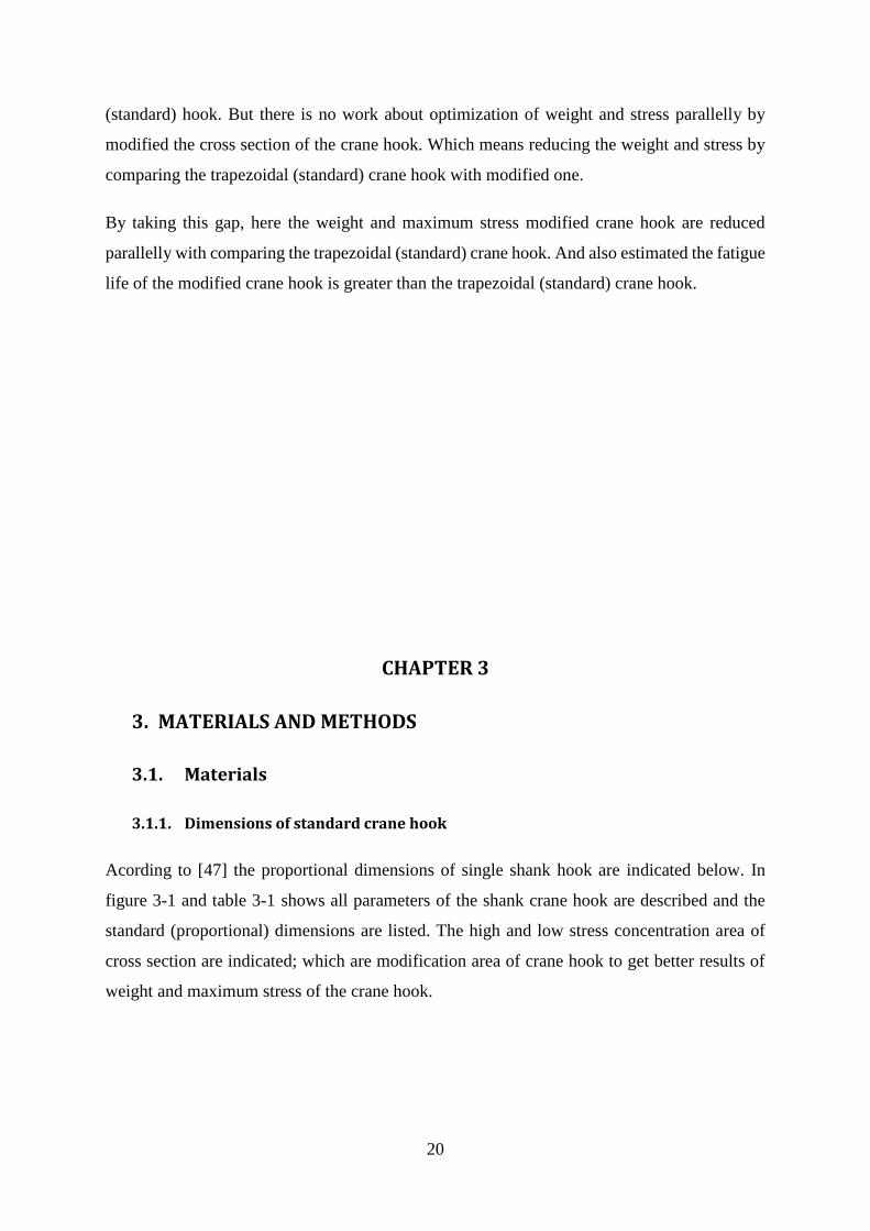
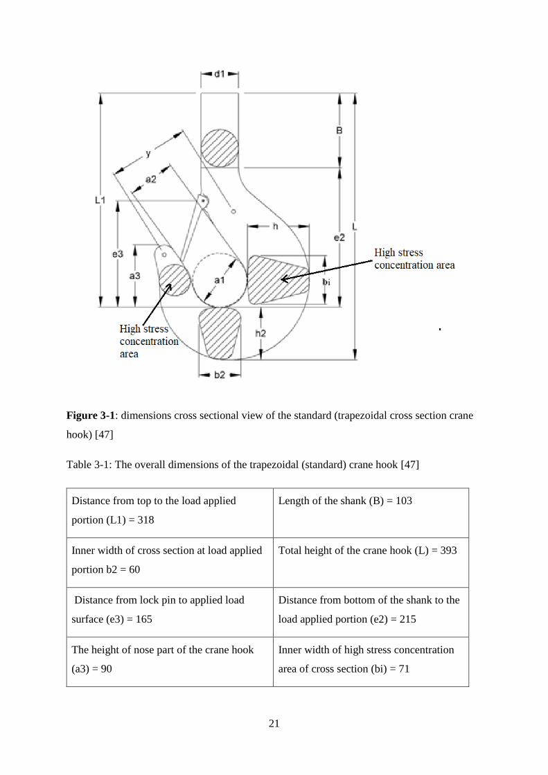
Acording to [47] the proportional dimensions of single shank hook are indicated below. In
figure 3-1 and table 3-1 shows all parameters of the shank crane hook are described and the
standard (proportional) dimensions are listed. The high and low stress concentration area of
cross section are indicated; which are modification area of crane hook to get better results of
weight and maximum stress of the crane hook.
21
Figure 3-1: dimensions cross sectional view of the standard (trapezoidal cross section crane
hook) [47]
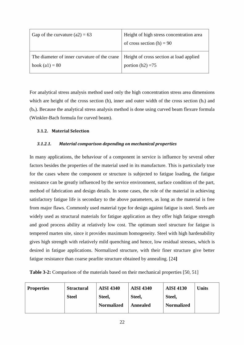
Table 3-1: The overall dimensions of the trapezoidal (standard) crane hook [47]
Distance from top to the load applied
portion (L1) = 318
Length of the shank (B) = 103
Inner width of cross section at load applied
portion b2 = 60
Total height of the crane hook (L) = 393
Distance from lock pin to applied load
surface (e3) = 165
Distance from bottom of the shank to the
load applied portion (e2) = 215
The height of nose part of the crane hook
(a3) = 90
Inner width of high stress concentration
area of cross section (bi) = 71
22
Gap of the curvature (a2) = 63 Height of high stress concentration area
of cross section (h) = 90
The diameter of inner curvature of the crane
hook (a1) = 80
Height of cross section at load applied
portion (h2) =75
For analytical stress analysis method used only the high concentration stress area dimensions
which are height of the cross section (h), inner and outer width of the cross section (bi) and
(bo). Because the analytical stress analysis method is done using curved beam flexure formula
(Winkler-Bach formula for curved beam).
3.1.2. Material Selection
3.1.2.1. Material comparison depending on mechanical properties
In many applications, the behaviour of a component in service is influence by several other
factors besides the properties of the material used in its manufacture. This is particularly true
for the cases where the component or structure is subjected to fatigue loading, the fatigue
resistance can be greatly influenced by the service environment, surface condition of the part,
method of fabrication and design details. In some cases, the role of the material in achieving
satisfactory fatigue life is secondary to the above parameters, as long as the material is free
from major flaws. Commonly used material type for design against fatigue is steel. Steels are
widely used as structural materials for fatigue application as they offer high fatigue strength
and good process ability at relatively low cost. The optimum steel structure for fatigue is
tempered marten site, since it provides maximum homogeneity. Steel with high hardenability
gives high strength with relatively mild quenching and hence, low residual stresses, which is
desired in fatigue applications. Normalized structure, with their finer structure give better
fatigue resistance than coarse pearlite structure obtained by annealing. [24]
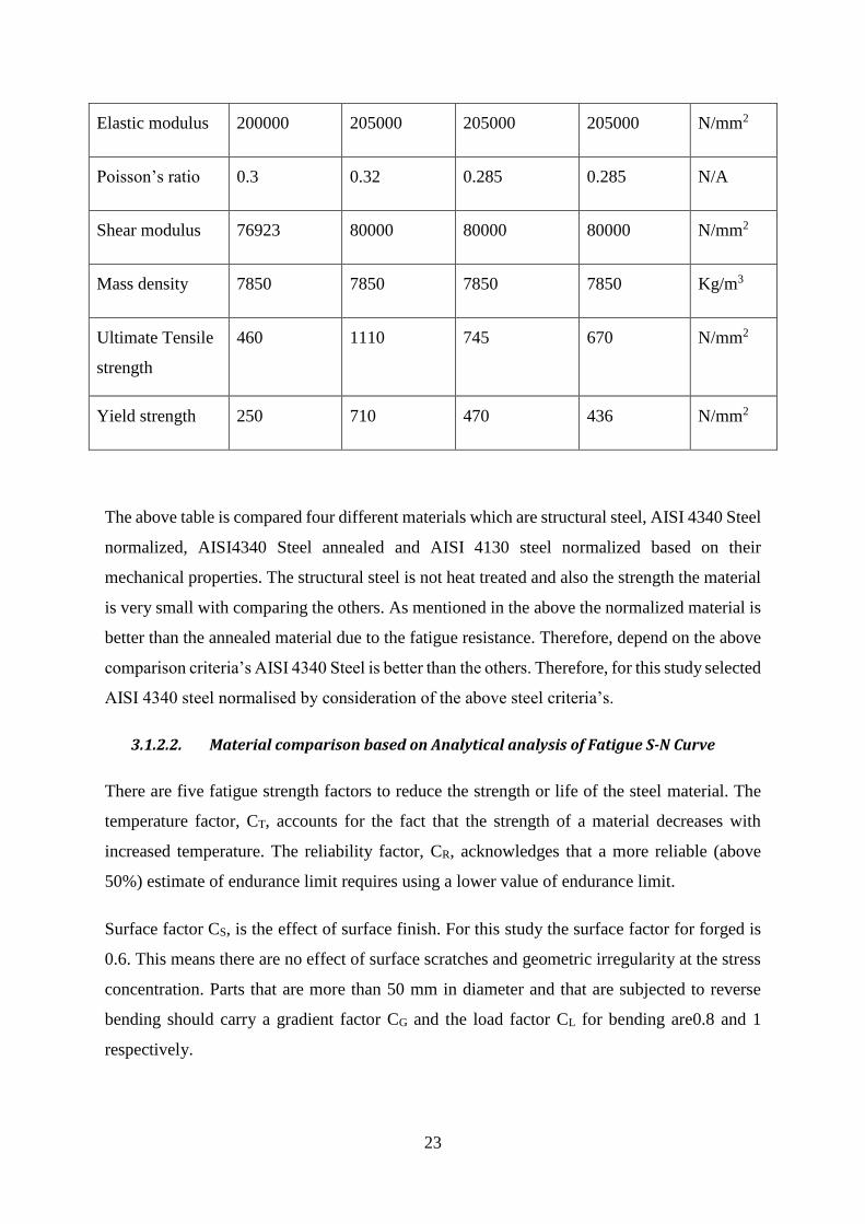
Table 3-2: Comparison of the materials based on their mechanical properties [50, 51]
Properties Stractural
Steel
AISI 4340
Steel,
Normalized
AISI 4340
Steel,
Annealed
AISI 4130
Steel,
Normalized
Units
23
Elastic modulus 200000 205000 205000 205000 N/mm2
Poisson’s ratio 0.3 0.32 0.285 0.285 N/A
Shear modulus 76923 80000 80000 80000 N/mm2
Mass density 7850 7850 7850 7850 Kg/m3
Ultimate Tensile
strength
460 1110 745 670 N/mm2
Yield strength 250 710 470 436 N/mm2
The above table is compared four different materials which are structural steel, AISI 4340 Steel
normalized, AISI4340 Steel annealed and AISI 4130 steel normalized based on their
mechanical properties. The structural steel is not heat treated and also the strength the material
is very small with comparing the others. As mentioned in the above the normalized material is
better than the annealed material due to the fatigue resistance. Therefore, depend on the above
comparison criteria’s AISI 4340 Steel is better than the others. Therefore, for this study selected
AISI 4340 steel normalised by consideration of the above steel criteria’s.
3.1.2.2. Material comparison based on Analytical analysis of Fatigue S-N Curve
There are five fatigue strength factors to reduce the strength or life of the steel material. The
temperature factor, CT, accounts for the fact that the strength of a material decreases with
increased temperature. The reliability factor, CR, acknowledges that a more reliable (above
50%) estimate of endurance limit requires using a lower value of endurance limit.
Surface factor CS, is the effect of surface finish. For this study the surface factor for forged is
0.6. This means there are no effect of surface scratches and geometric irregularity at the stress
concentration. Parts that are more than 50 mm in diameter and that are subjected to reverse
bending should carry a gradient factor CG and the load factor CL for bending are0.8 and 1
respectively.
24
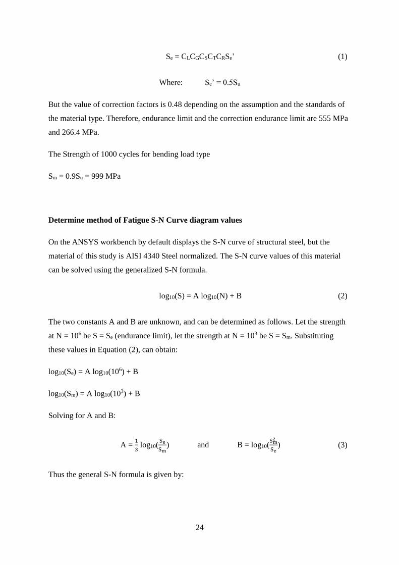
Se = CLCGCSCTCRSe’ (1)
Where: Se’ = 0.5Su
But the value of correction factors is 0.48 depending on the assumption and the standards of
the material type. Therefore, endurance limit and the correction endurance limit are 555 MPa
and 266.4 MPa.
The Strength of 1000 cycles for bending load type
Sm = 0.9Su = 999 MPa
Determine method of Fatigue S-N Curve diagram values
On the ANSYS workbench by default displays the S-N curve of structural steel, but the
material of this study is AISI 4340 Steel normalized. The S-N curve values of this material
can be solved using the generalized S-N formula.
log10(S) = A log10(N) + B (2)
The two constants A and B are unknown, and can be determined as follows. Let the strength
at N = 106 be S = Se (endurance limit), let the strength at N = 103 be S = Sm. Substituting
these values in Equation (2), can obtain:
log10(Se) = A log10(106) + B
log10(Sm) = A log10(103) + B
Solving for A and B:
A = 1
3 log10(
Se
Sm) and B = log10(
Sm2
Se) (3)
Thus the general S-N formula is given by:
25
log10(S) = 1
3 log10(
Se
Sm) log10(N) + log10(
Sm2
Se) (4)
Now by substituting any value number of cycles (N) in equation (4) can find the
corresponding strength (alternating stress).
Similarly, can determine the Sm, Se and fatigue S-N diagram values for structural steel, AISI
4340 steel annealed and 4130 steel normalized by using general S-N formula. The table is
compares three different materials based on the S-N curve values. In the previous section These
materials are compared with mechanical properties and fatigue resistance ability. Here also
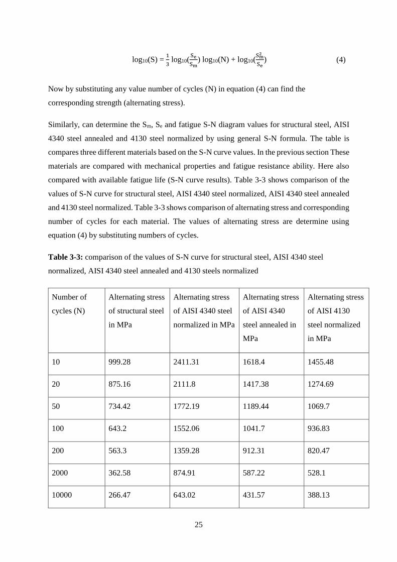
compared with available fatigue life (S-N curve results). Table 3-3 shows comparison of the
values of S-N curve for structural steel, AISI 4340 steel normalized, AISI 4340 steel annealed
and 4130 steel normalized. Table 3-3 shows comparison of alternating stress and corresponding
number of cycles for each material. The values of alternating stress are determine using
equation (4) by substituting numbers of cycles.
Table 3-3: comparison of the values of S-N curve for structural steel, AISI 4340 steel
normalized, AISI 4340 steel annealed and 4130 steels normalized
Number of
cycles (N)
Alternating stress
of structural steel
in MPa
Alternating stress
of AISI 4340 steel
normalized in MPa
Alternating stress
of AISI 4340
steel annealed in
MPa
Alternating stress
of AISI 4130
steel normalized
in MPa
10 999.28 2411.31 1618.4 1455.48
20 875.16 2111.8 1417.38 1274.69
50 734.42 1772.19 1189.44 1069.7
100 643.2 1552.06 1041.7 936.83
200 563.3 1359.28 912.31 820.47
2000 362.58 874.91 587.22 528.1
10000 266.47 643.02 431.57 388.13
26
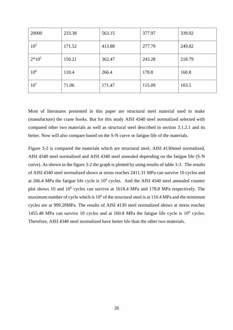
20000 233.38 563.15 377.97 339.92
105 171.52 413.88 277.79 249.82
2*105 150.21 362.47 243.28 218.79
106 110.4 266.4 178.8 160.8
107 71.06 171.47 115.09 103.5
Most of literatures presented in this paper are structural steel material used to make
(manufacture) the crane hooks. But for this study AISI 4340 steel normalized selected with
compared other two materials as well as structural steel described in section 3.1.2.1 and its
better. Now will also compare based on the S-N curve or fatigue life of the materials.
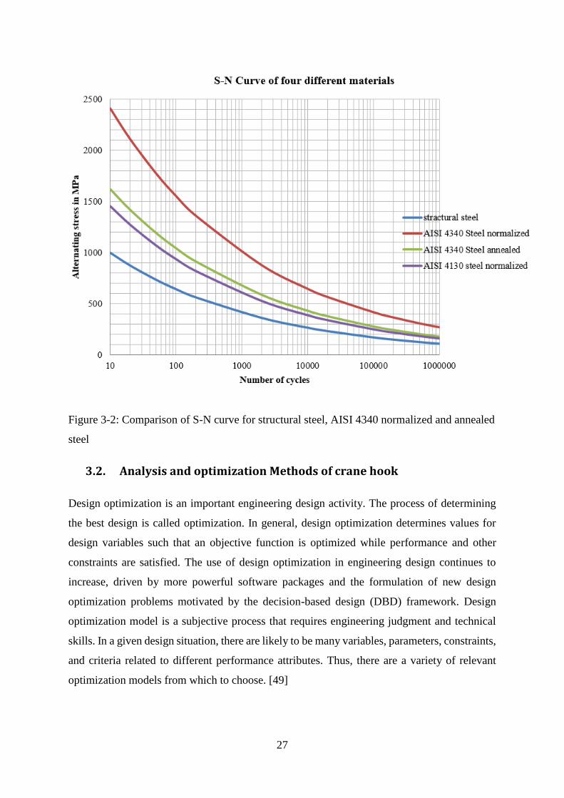
Figure 3-2 is compared the materials which are structural steel, AISI 4130steel normalized,
AISI 4340 steel normalized and AISI 4340 steel annealed depending on the fatigue life (S-N
curve). As shown in the figure 3-2 the graph is plotted by using results of table 3-3. The results
of AISI 4340 steel normalized shows at stress reaches 2411.31 MPa can survive 10 cycles and
at 266.4 MPa the fatigue life cycle is 106 cycles. And the AISI 4340 steel annealed counter
plot shows 10 and 106 cycles can survive at 1618.4 MPa and 178.8 MPa respectively. The
maximum number of cycle which is 106 of the structural steel is at 110.4 MPa and the minimum
cycles are at 999.28MPa. The results of AISI 4130 steel normalized shows at stress reaches
1455.48 MPa can survive 10 cycles and at 160.8 MPa the fatigue life cycle is 106 cycles.
Therefore, AISI 4340 steel normalized have better life than the other two materials.
27
Figure 3-2: Comparison of S-N curve for structural steel, AISI 4340 normalized and annealed
steel
3.2. Analysis and optimization Methods of crane hook
Design optimization is an important engineering design activity. The process of determining
the best design is called optimization. In general, design optimization determines values for
design variables such that an objective function is optimized while performance and other
constraints are satisfied. The use of design optimization in engineering design continues to
increase, driven by more powerful software packages and the formulation of new design
optimization problems motivated by the decision-based design (DBD) framework. Design
optimization model is a subjective process that requires engineering judgment and technical
skills. In a given design situation, there are likely to be many variables, parameters, constraints,
and criteria related to different performance attributes. Thus, there are a variety of relevant
optimization models from which to choose. [49]
28
The design and analysis of crane hook is done by considered as curved beam. Crane hooks with
trapezoidal, circular, rectangular and triangular cross section are commonly used. From
literatures presented in this paper trapezoidal cross section hook is better than the other cross
sections. This study deals with the study of crane hook consists the trapezoidal cross sections
as well as the modification of standard hook in which the weight optimization is done by
changing cross section. In this study there are three modified cross sectional hooks. Sometimes
an accident may occur due to stress concentration factor in it so stress analysis is necessary
before make it applicable. And stress analysis is studied in ANSYS workbench 17.2. Now the
model and analysis both are carried out by software’s. So; it must be designed to deliver
maximum performance without failure.
In this study there are four type of cross-section for crane hook namely model-1, model-2,
Model-3 and trapezoidal (standard). The theoretical stress calculation is done depend on the
cross-section type. All four cross-sections are modelled in SOLIDWORK 17 software. Then,
saving. igs file is used further for analysis. After modelling the four types of crane hook cross-
sections its. igs file which is saved in SOLIDWORK is imported in ANSYS workbench
software and by applying load and proper boundary constraints its analysis is obtained. The
results of stress obtained in ANSYS are compared with theoretical calculations and based on
the result section having least stress concentration is taken for further optimization.
For this method of optimization, geometry optimization is used as a tool. And based on high
and less stress concentration the cross-sectional dimensions are changed. Here there are three
new modelled (modified) cross sections which are model 1, model 2 and model 3. In the method
of model 1 by reduced and changed the high stress concentration area of cross section. Which
are by varying the inner and outer width of the cross sections and keep the height of cross
section is constant. In the method of model 2 the geometry is modified by reducing the both
sides of the curved member of hook cross section. In the case of model 3 by increase the cross
section of high stress concentration area. And reduce and change the cross section of low stress
concentration area. Finally, the new modified crane hook models are compared with the
trapezoidal (existing) crane hook based on the FEM analysis and selected the best one crane
hook.
For this study used three types of geometric modifications to optimize the weight and
maximum stress of the hook. Which are model-1, model-2 and model-3. And the results of
each modified hooks are compared with trapezoidal hook results based on different criteria’s
29
which are max stress, maximum equivalent strain, maximum deformation, weight and fatigue
life of the hooks. The applied load for all cross section is the same which is 4.5 tons. And
compared the modified hooks each to other then selected the best (better) model.
3.2.1. Methods of Modified Geometry 1 (Model -1)
For this modified hook (Model-1) the independent parameters of high stressed area of cross
section are width of inner side (bi) and width of outer side (bo). There are three Iterations having
different width of inner side (bi) and width of outer side (bo) but the cross sectional areas are
the same for all Iterations. By adjust (varying) these parameters analysed the stress and selected
cross section having better maximum equivalent stress which is Iteration 2 to compare with
other model hooks (model-2 and model-3). And the dependent parameters are material
properties, the radius of curvature, height of cross section and applied load. By analysed of
selected cross section the result of analysed functions are in safe condition.
The two parallel sides of crane hook cross-section namely ‘bi’ & ‘b0’ are taken as design
variables where ‘bi’ is width of inner side and ‘bo’ is width of outer side of the cross section of
crane hook.
Table 3-4: Analysed variables and analysed functions for this model-1 optimization case
Analysed variables Analysed functions
✓ width of outer side (bo) ✓ Weight (reduced the weight)
✓ width of inner side (bi) ✓ Maximum (von-mises) stress ( less than the
yield stress of the material)
✓ Total deformation
✓ Equivalent elastic strain
30
Table 3-5: comparison of three different Iterations to select one of these
cross sections Area of the
cross section
(A)
width of outer
side of the cross
section (b0)
width of inner
side of the cross
section (bi)
Maximum
Equivalent (von-
mises) stress
Iteration 1 4702.5 mm2 36.5mm 68mm 86.83 MPa
Iteration 2 4702.5 mm2 33.5mm 71mm 85.30 MPa
Iteration 3 4702.5 mm2 35mm 69.5mm 86.04 MPa
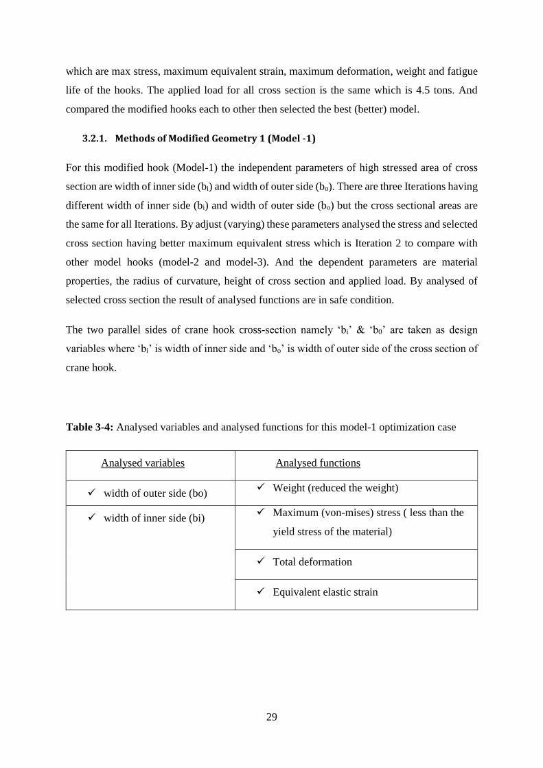
Figure 3-3: cross section of selected iteration (iteration 2)
The dimensions of ‘bi’ & ‘b0’ for this crane hook 71mm & 33.5mm for the big cross section
hook (maximum stress concentration area of cross section). The height and cross sectional area
of all iterations are the same the only variables are ‘bi’ & ‘b0’. Therefore, they have the same
weight the comparison is only based on the stress. Based on this, best one iteration is selected
out of the 3 iterations to compare with other model hooks (model-2 and model-3) shown in
table3-5. By changing (varying) the analysed variables obtained a new optimized design. The
above comparison results are obtained by analytical analysis. And Based on the stress
comparison of the above 3 iterations, iteration 2 is having better max stress concentration
(having less than the other two trials).
31
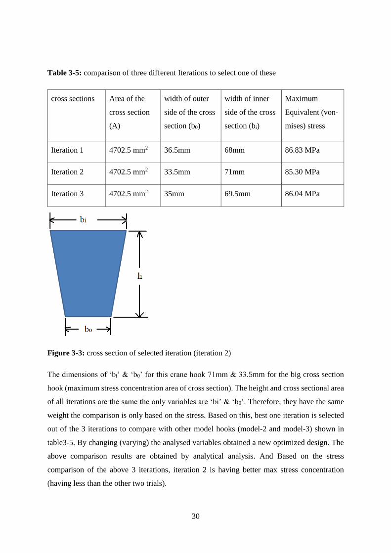
3.2.2. Methods of Modified Geometry 2 (Model -2)
In this optimization method the geometry is modified by reducing the both sides of the curved
member of hook cross section. The load is applied on the curved inner surface of the hook.
Actually the modified cross section is thin at the middle. But there is no any reaction force on
the opposite surface (outer surface) of the applied force. Therefore, it is not subjected to
buckling.
Figure 3-4: cross section of model 2 crane hook
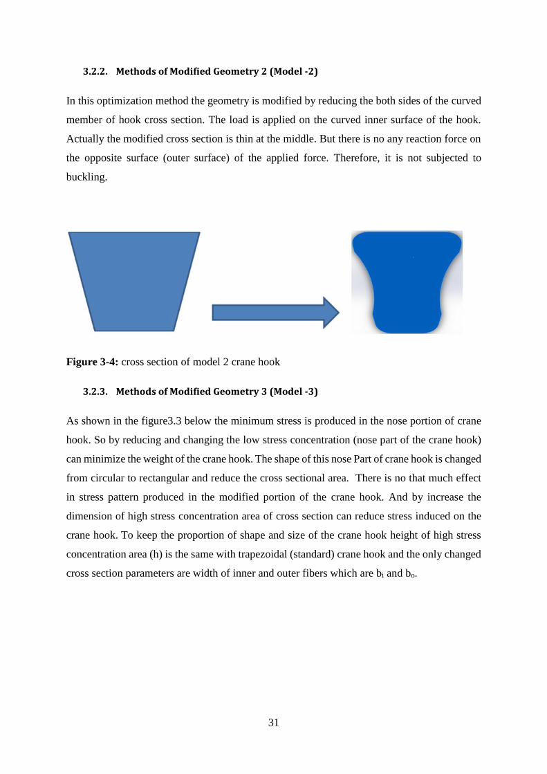
3.2.3. Methods of Modified Geometry 3 (Model -3)
As shown in the figure3.3 below the minimum stress is produced in the nose portion of crane
hook. So by reducing and changing the low stress concentration (nose part of the crane hook)
can minimize the weight of the crane hook. The shape of this nose Part of crane hook is changed
from circular to rectangular and reduce the cross sectional area. There is no that much effect
in stress pattern produced in the modified portion of the crane hook. And by increase the
dimension of high stress concentration area of cross section can reduce stress induced on the
crane hook. To keep the proportion of shape and size of the crane hook height of high stress
concentration area (h) is the same with trapezoidal (standard) crane hook and the only changed
cross section parameters are width of inner and outer fibers which are bi and bo.
32
Figure 3-5: Change and reduce the circular cross section at the nose part of the crane hook
and increase inner width of the high stress area (bi)
3.3. Analytical Methods in Structural Design of Crane Hook
According to the curved beam design theory components having curved beam portions are
frequently subjected to axial or bending loads or to a combination of bending and axial loads.
Structural design of crane hook is designed by considering as curved beam. The distribution of
stress in a curved flexural member is determined by using the following assumptions.
• The cross section has an axis of symmetry in a plane along the length of the beam.
• Plane cross sections remain plane after bending.
• The modulus of elasticity is the same in tension as in compression. [23]
The load condition of hook is the combination of bending moment and direct tensile load. The
inner surface of the hook is subjected to tensile stress and the outer surface subjected to
compression stress due to bending moment and direct tensile load.
According to the literatures presented in this paper concluded having trapezoidal cross section
crane hook is better than the other cross sectional hooks which are rectangular, circular and
triangular.

33
3.3.1. Stress analysis for trapezoidal crane hook
To design the trapezoidal cross section hook first draw should have to draw the curved beam
with its cross section to shows that the neutral and centroidal axes are not coincident. And also
show the parameters and the applied load on the curved beam (hook).
Figure 3-6: curved beam with its cross section to shows that the neutral and centroidal axes
are not coincident. [48]
The purpose of this design is to get safe condition of the hook due to maximum stress by
using appropriate design dimensions of the hook to lifting the applied load.
Radius of outer fiber (ro) = 130 mm
Radius of inner fiber (ri) = 40 mm
Width of the outer fiber (side) of the cross section (bo) = 35.5 mm
Width of the inner fiber (side) of the cross section (bi) = 71 mm
Depth of section (h) = 90 mm [47]
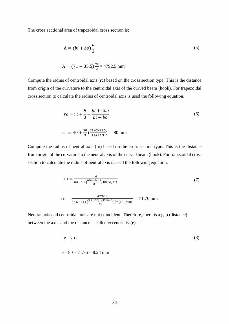
34
The cross sectional area of trapezoidal cross section is;
A = (𝑏𝑖 + 𝑏𝑜)
ℎ
2 (5)
A = (71 + 35.5)90
2 = 4792.5 mm2
Compute the radius of centroidal axis (rc) based on the cross section type. This is the distance
from origin of the curvature to the centroidal axis of the curved beam (hook). For trapezoidal
cross section to calculate the radius of centroidal axis is used the following equation.
𝑟𝑐 = 𝑟𝑖 +
ℎ
3+
𝑏𝑖 + 2𝑏𝑜
𝑏𝑖 + 𝑏𝑜 (6)
𝑟𝑐 = 40 +90
3(
71+2∗35.5
71+35.5) = 80 mm
Compute the radius of neutral axis (rn) based on the cross section type. This is the distance
from origin of the curvature to the neutral axis of the curved beam (hook). For trapezoidal cross
section to calculate the radius of neutral axis is used the following equation.
rn =𝐴
𝑏𝑜−𝑏𝑖+[𝑏𝑖𝑟𝑜−𝑏𝑜𝑟𝑖
ℎ] ln (𝑟𝑜/𝑟𝑖)
(7)
rn =4792.5
35.5−71+[(71∗130)−(35.5∗40)
90] ln (130/40)
= 71.76 mm
Neutral axis and centroidal axis are not coincident. Therefore, there is a gap (distance)
between the axes and the distance is called eccentricity (e).
e= rc-rn (8)
e= 80 – 71.76 = 8.24 mm
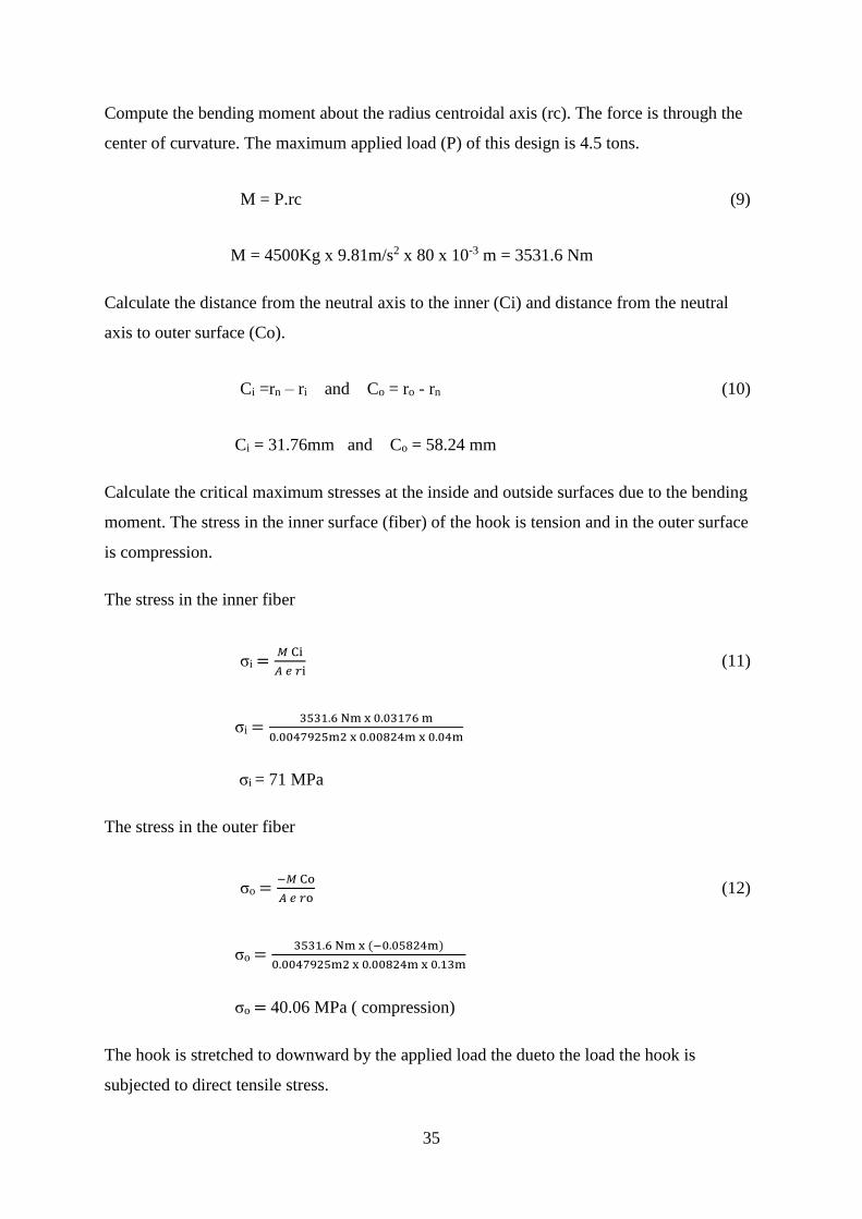
35
Compute the bending moment about the radius centroidal axis (rc). The force is through the
center of curvature. The maximum applied load (P) of this design is 4.5 tons.
M = P.rc (9)
M = 4500Kg x 9.81m/s2 x 80 x 10-3 m = 3531.6 Nm
Calculate the distance from the neutral axis to the inner (Ci) and distance from the neutral
axis to outer surface (Co).
Ci =rn – ri and Co = ro - rn (10)
Ci = 31.76mm and Co = 58.24 mm
Calculate the critical maximum stresses at the inside and outside surfaces due to the bending
moment. The stress in the inner surface (fiber) of the hook is tension and in the outer surface
is compression.
The stress in the inner fiber
σi =𝑀 Ci
𝐴 𝑒 𝑟i (11)
σi =3531.6 Nm x 0.03176 m
0.0047925m2 x 0.00824m x 0.04m
σi = 71 MPa
The stress in the outer fiber
σo =−𝑀 Co
𝐴 𝑒 𝑟o (12)
σo =3531.6 Nm x (−0.05824m)
0.0047925m2 x 0.00824m x 0.13m
σo = 40.06 MPa ( compression)
The hook is stretched to downward by the applied load the dueto the load the hook is
subjected to direct tensile stress.

36
σt =𝑃
𝐴 (13)
σt = 4500 𝑥 9.81
0.0047925
σt = 9.21 MPa
Calculate the resultant stresses at the inner and outer surface add or subtract maximum stresses
at inner and outer surfaces from direct stresses (using superposition) because the hook is
subjected to bending and direct tensile stress.
The resultant stress in the inner surface (fiber)
σRi = σt + σi = 80.21 MPa (14)
The resultant stress in the outer surface (fiber)
σRo = σt – σo = 30.85 MPa ( compression) (15)
3.3.2. Stress analysis for model -1 crane hook
All cross sectional dimension except width of outer side of the cross section of model 1 crane
hook are the same with trapezoidal crane hook cross sections. The changed dimension is only
width of the outer side of the cross section. Therefore, Model 1 crane hook can design with
the same procedure of the trapezoidal crane hook. Figure 3-7 shows the cross sectional
dimensions of high stress concentration area of model-1 crane hook.
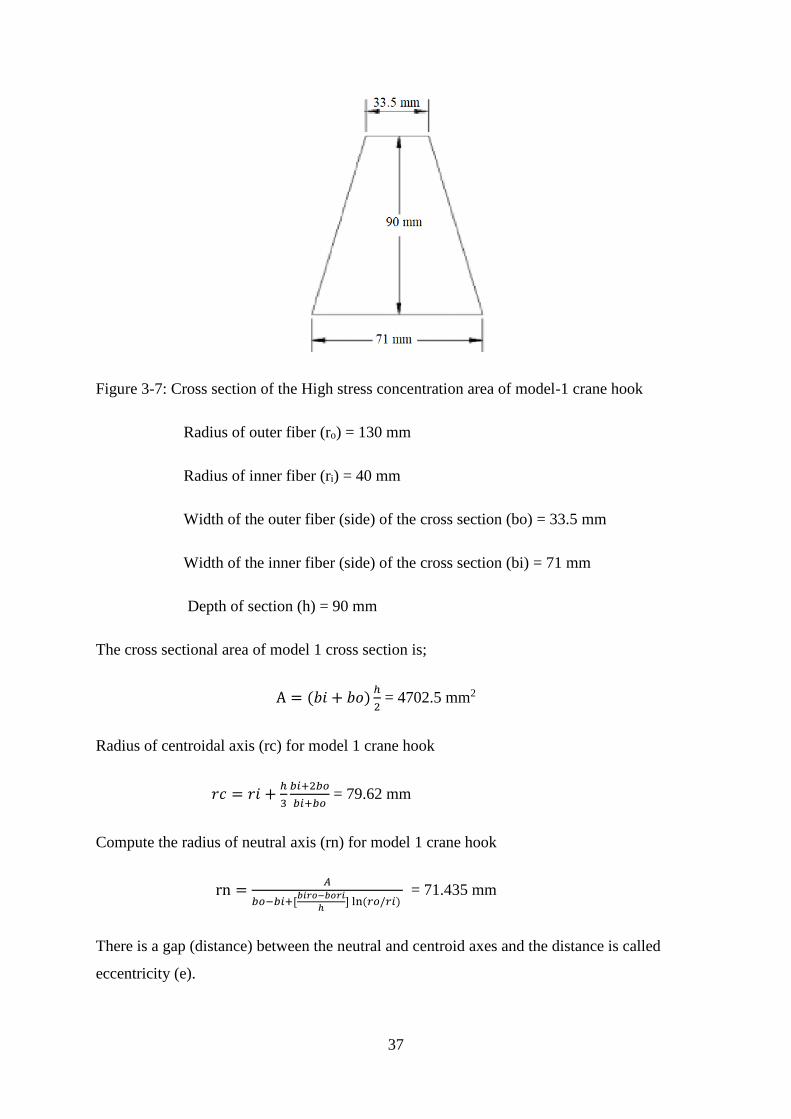
37
Figure 3-7: Cross section of the High stress concentration area of model-1 crane hook
Radius of outer fiber (ro) = 130 mm
Radius of inner fiber (ri) = 40 mm
Width of the outer fiber (side) of the cross section (bo) = 33.5 mm
Width of the inner fiber (side) of the cross section (bi) = 71 mm
Depth of section (h) = 90 mm
The cross sectional area of model 1 cross section is;
A = (𝑏𝑖 + 𝑏𝑜)ℎ
2 = 4702.5 mm2
Radius of centroidal axis (rc) for model 1 crane hook
𝑟𝑐 = 𝑟𝑖 +ℎ
3
𝑏𝑖+2𝑏𝑜
𝑏𝑖+𝑏𝑜 = 79.62 mm
Compute the radius of neutral axis (rn) for model 1 crane hook
rn =𝐴
𝑏𝑜−𝑏𝑖+[𝑏𝑖𝑟𝑜−𝑏𝑜𝑟𝑖
ℎ] ln (𝑟𝑜/𝑟𝑖)
= 71.435 mm
There is a gap (distance) between the neutral and centroid axes and the distance is called
eccentricity (e).
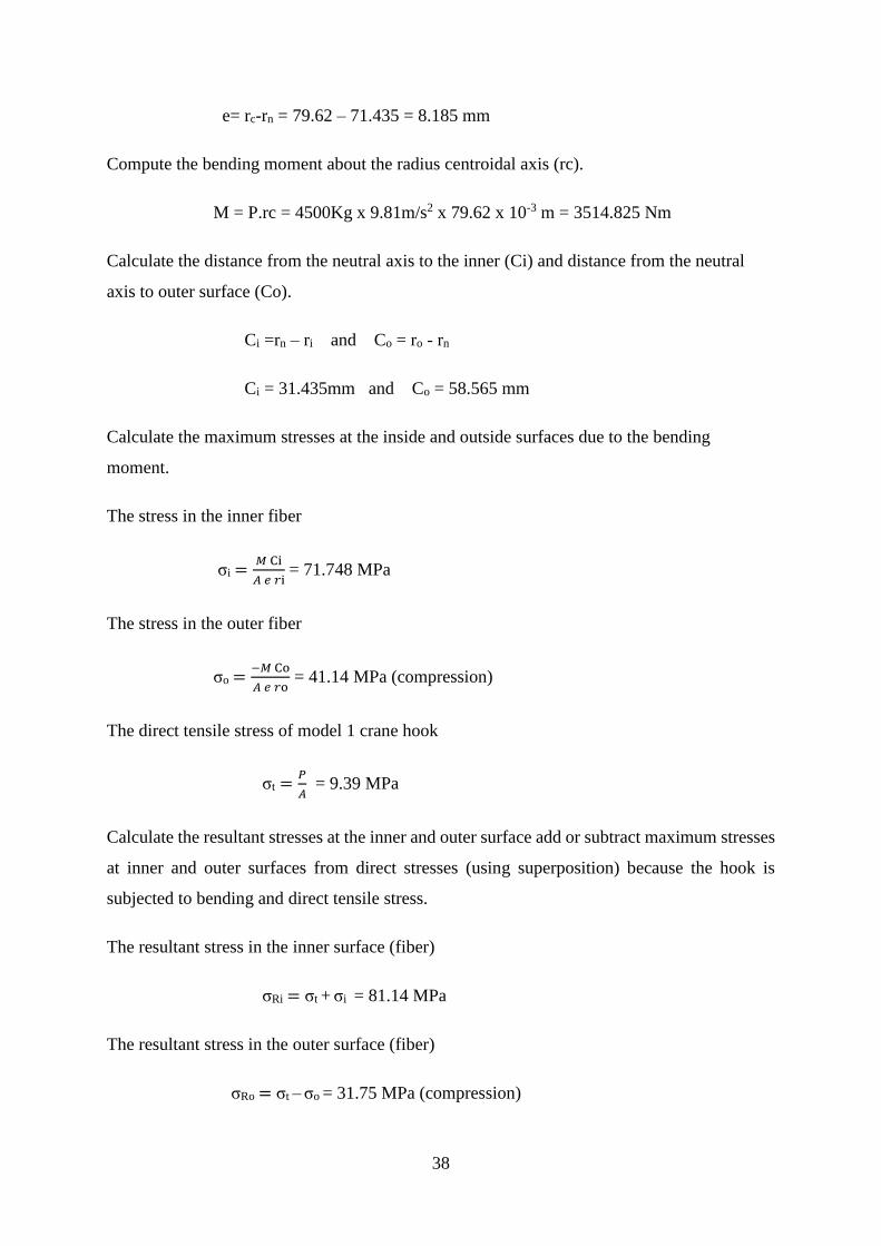
38
e= rc-rn = 79.62 – 71.435 = 8.185 mm
Compute the bending moment about the radius centroidal axis (rc).
M = P.rc = 4500Kg x 9.81m/s2 x 79.62 x 10-3 m = 3514.825 Nm
Calculate the distance from the neutral axis to the inner (Ci) and distance from the neutral
axis to outer surface (Co).
Ci =rn – ri and Co = ro - rn
Ci = 31.435mm and Co = 58.565 mm
Calculate the maximum stresses at the inside and outside surfaces due to the bending
moment.
The stress in the inner fiber
σi =𝑀 Ci
𝐴 𝑒 𝑟i = 71.748 MPa
The stress in the outer fiber
σo =−𝑀 Co
𝐴 𝑒 𝑟o = 41.14 MPa (compression)
The direct tensile stress of model 1 crane hook
σt =𝑃
𝐴 = 9.39 MPa
Calculate the resultant stresses at the inner and outer surface add or subtract maximum stresses
at inner and outer surfaces from direct stresses (using superposition) because the hook is
subjected to bending and direct tensile stress.
The resultant stress in the inner surface (fiber)
σRi = σt + σi = 81.14 MPa
The resultant stress in the outer surface (fiber)
σRo = σt – σo = 31.75 MPa (compression)
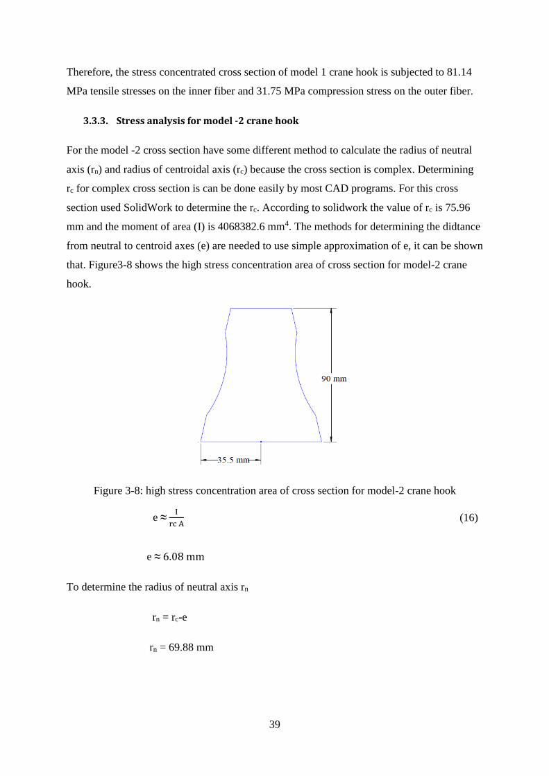
39
Therefore, the stress concentrated cross section of model 1 crane hook is subjected to 81.14
MPa tensile stresses on the inner fiber and 31.75 MPa compression stress on the outer fiber.
3.3.3. Stress analysis for model -2 crane hook
For the model -2 cross section have some different method to calculate the radius of neutral
axis (rn) and radius of centroidal axis (rc) because the cross section is complex. Determining
rc for complex cross section is can be done easily by most CAD programs. For this cross
section used SolidWork to determine the rc. According to solidwork the value of rc is 75.96
mm and the moment of area (I) is 4068382.6 mm4. The methods for determining the didtance
from neutral to centroid axes (e) are needed to use simple approximation of e, it can be shown
that. Figure3-8 shows the high stress concentration area of cross section for model-2 crane
hook.
Figure 3-8: high stress concentration area of cross section for model-2 crane hook
e ≈ I
rc A (16)
e ≈ 6.08 mm
To determine the radius of neutral axis rn
rn = rc-e
rn = 69.88 mm
40
The bending moment about the centroid of the cross section
M = P.rc = 4500Kg x 9.81m/s2 x 75.96 x 10-3 m = 3353.2542 Nm
Calculate the distance from the neutral axis to the inner (Ci) and distance from the neutral
axis to outer surface (Co).
Ci =rn – ri and Co = ro - rn
Ci = 29.88 mm and Co = 60.12 mm
Calculate the resultant stresses at the inner and outer surface add or subtract maximum stresses
at inner and outer surfaces from direct stresses (using superposition) because the hook is
subjected to bending and direct tensile stress.
The resultant stress in the inner surface (fiber)
σRi = σt + σi
σRi = 𝑃
𝐴 +
𝑀 Ci
𝐴 𝑒 𝑟i = 103.54 MPa
The resultant stress in the outer surface (fiber)
σRo = σt – σo
σRo = 𝑃
𝐴 -
𝑀 Ci
𝐴 𝑒 𝑟i = -47.87 MPa
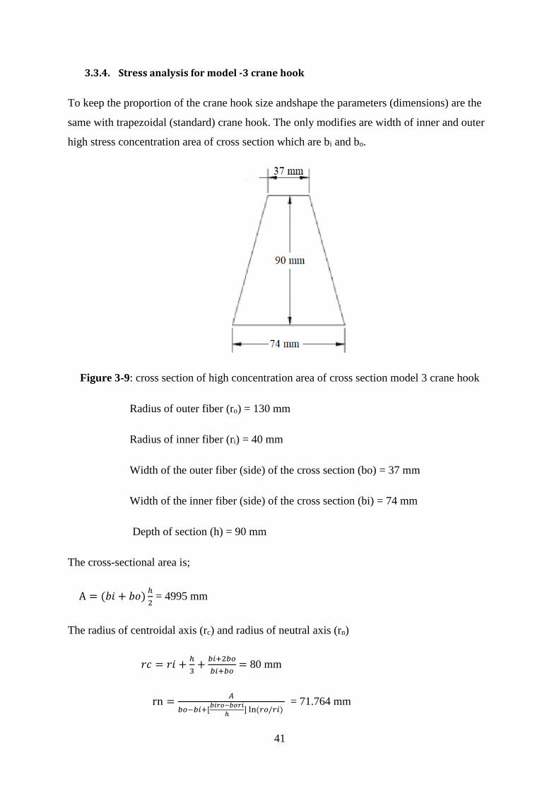
41
3.3.4. Stress analysis for model -3 crane hook
To keep the proportion of the crane hook size andshape the parameters (dimensions) are the
same with trapezoidal (standard) crane hook. The only modifies are width of inner and outer
high stress concentration area of cross section which are bi and bo.
Figure 3-9: cross section of high concentration area of cross section model 3 crane hook
Radius of outer fiber (ro) = 130 mm
Radius of inner fiber (ri) = 40 mm
Width of the outer fiber (side) of the cross section (bo) = 37 mm
Width of the inner fiber (side) of the cross section (bi) = 74 mm
Depth of section (h) = 90 mm
The cross-sectional area is;
A = (𝑏𝑖 + 𝑏𝑜)ℎ
2 = 4995 mm
The radius of centroidal axis (rc) and radius of neutral axis (rn)
𝑟𝑐 = 𝑟𝑖 +ℎ
3+
𝑏𝑖+2𝑏𝑜
𝑏𝑖+𝑏𝑜 = 80 mm
rn =𝐴
𝑏𝑜−𝑏𝑖+[𝑏𝑖𝑟𝑜−𝑏𝑜𝑟𝑖
ℎ] ln (𝑟𝑜/𝑟𝑖)
= 71.764 mm
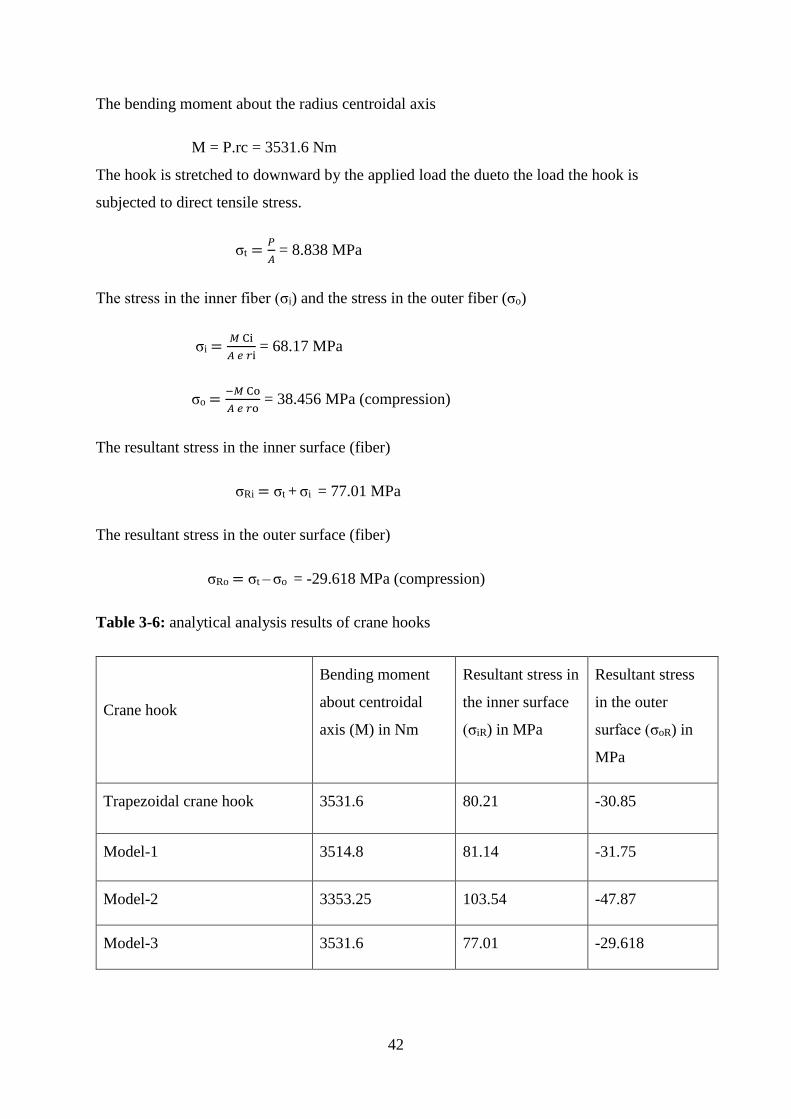
42
The bending moment about the radius centroidal axis
M = P.rc = 3531.6 Nm
The hook is stretched to downward by the applied load the dueto the load the hook is
subjected to direct tensile stress.
σt =𝑃
𝐴 = 8.838 MPa
The stress in the inner fiber (σi) and the stress in the outer fiber (σo)
σi =𝑀 Ci
𝐴 𝑒 𝑟i = 68.17 MPa
σo =−𝑀 Co
𝐴 𝑒 𝑟o = 38.456 MPa (compression)
The resultant stress in the inner surface (fiber)
σRi = σt + σi = 77.01 MPa
The resultant stress in the outer surface (fiber)
σRo = σt – σo = -29.618 MPa (compression)
Table 3-6: analytical analysis results of crane hooks
Crane hook
Bending moment
about centroidal
axis (M) in Nm
Resultant stress in
the inner surface
(σiR) in MPa
Resultant stress
in the outer
surface (σoR) in
MPa
Trapezoidal crane hook 3531.6 80.21 -30.85
Model-1 3514.8 81.14 -31.75
Model-2 3353.25 103.54 -47.87
Model-3 3531.6 77.01 -29.618
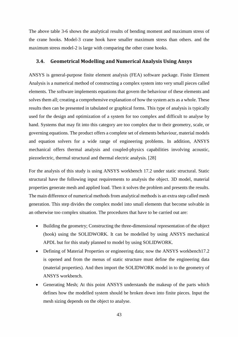
43
The above table 3-6 shows the analytical results of bending moment and maximum stress of
the crane hooks. Model-3 crane hook have smaller maximum stress than others. and the
maximum stress model-2 is large with comparing the other crane hooks.
3.4. Geometrical Modelling and Numerical Analysis Using Ansys
ANSYS is general-purpose finite element analysis (FEA) software package. Finite Element
Analysis is a numerical method of constructing a complex system into very small pieces called
elements. The software implements equations that govern the behaviour of these elements and
solves them all; creating a comprehensive explanation of how the system acts as a whole. These
results then can be presented in tabulated or graphical forms. This type of analysis is typically
used for the design and optimization of a system for too complex and difficult to analyse by
hand. Systems that may fit into this category are too complex due to their geometry, scale, or
governing equations. The product offers a complete set of elements behaviour, material models
and equation solvers for a wide range of engineering problems. In addition, ANSYS
mechanical offers thermal analysis and coupled-physics capabilities involving acoustic,
piezoelectric, thermal structural and thermal electric analysis. [28]
For the analysis of this study is using ANSYS workbench 17.2 under static structural. Static
structural have the following input requirements to analysis the object. 3D model, material
properties generate mesh and applied load. Then it solves the problem and presents the results.
The main difference of numerical methods from analytical methods is an extra step called mesh
generation. This step divides the complex model into small elements that become solvable in
an otherwise too complex situation. The procedures that have to be carried out are:
• Building the geometry; Constructing the three-dimensional representation of the object
(hook) using the SOLIDWORK. It can be modelled by using ANSYS mechanical
APDL but for this study planned to model by using SOLIDWORK.
• Defining of Material Properties or engineering data; now the ANSYS workbench17.2
is opened and from the menus of static structure must define the engineering data
(material properties). And then import the SOLIDWORK model in to the geometry of
ANSYS workbench.
• Generating Mesh; At this point ANSYS understands the makeup of the parts which
defines how the modelled system should be broken down into finite pieces. Input the
mesh sizing depends on the object to analyse.
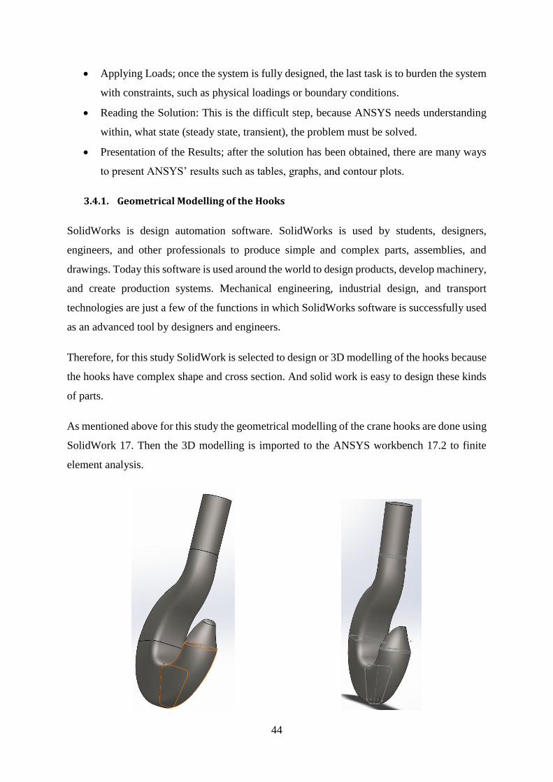
44
• Applying Loads; once the system is fully designed, the last task is to burden the system
with constraints, such as physical loadings or boundary conditions.
• Reading the Solution: This is the difficult step, because ANSYS needs understanding
within, what state (steady state, transient), the problem must be solved.
• Presentation of the Results; after the solution has been obtained, there are many ways
to present ANSYS’ results such as tables, graphs, and contour plots.
3.4.1. Geometrical Modelling of the Hooks
SolidWorks is design automation software. SolidWorks is used by students, designers,
engineers, and other professionals to produce simple and complex parts, assemblies, and
drawings. Today this software is used around the world to design products, develop machinery,
and create production systems. Mechanical engineering, industrial design, and transport
technologies are just a few of the functions in which SolidWorks software is successfully used
as an advanced tool by designers and engineers.
Therefore, for this study SolidWork is selected to design or 3D modelling of the hooks because
the hooks have complex shape and cross section. And solid work is easy to design these kinds
of parts.
As mentioned above for this study the geometrical modelling of the crane hooks are done using
SolidWork 17. Then the 3D modelling is imported to the ANSYS workbench 17.2 to finite
element analysis.
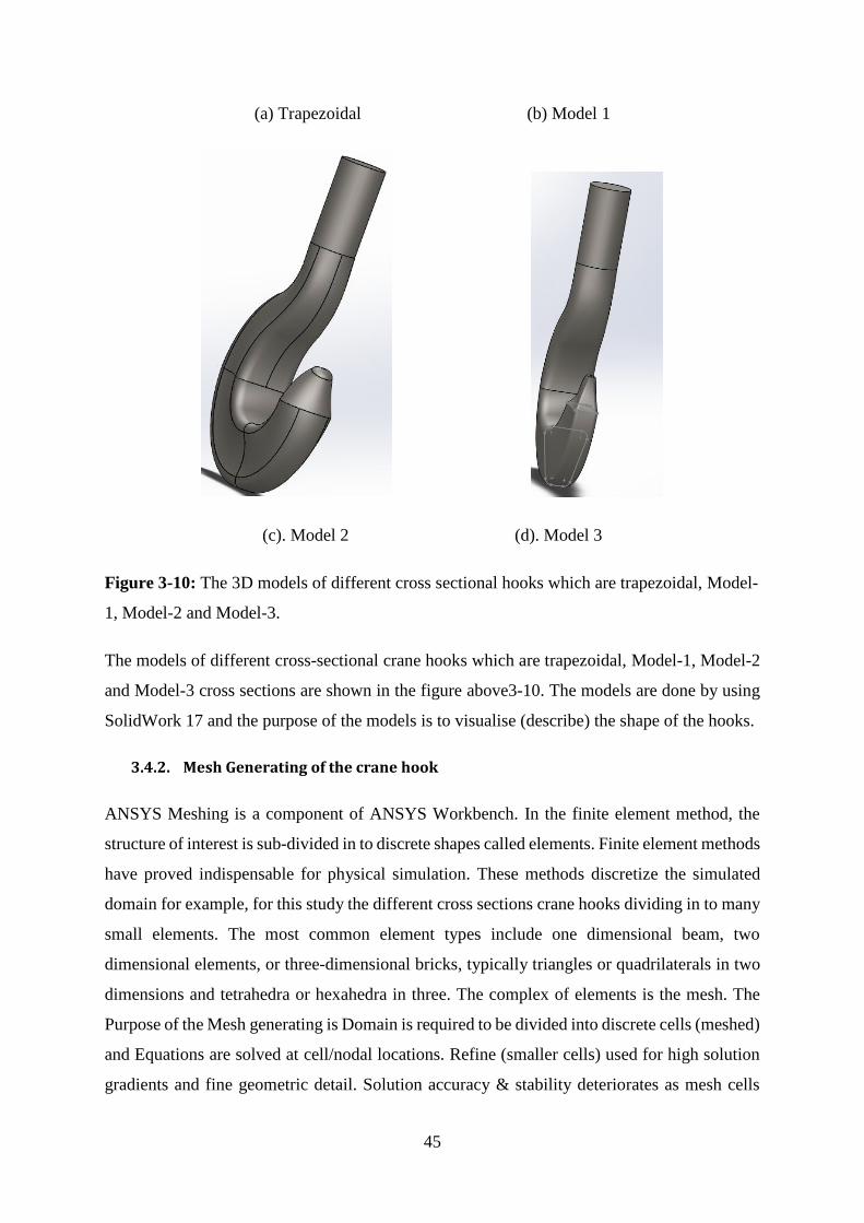
45
(a) Trapezoidal (b) Model 1
(c). Model 2 (d). Model 3
Figure 3-10: The 3D models of different cross sectional hooks which are trapezoidal, Model-
1, Model-2 and Model-3.
The models of different cross-sectional crane hooks which are trapezoidal, Model-1, Model-2
and Model-3 cross sections are shown in the figure above3-10. The models are done by using
SolidWork 17 and the purpose of the models is to visualise (describe) the shape of the hooks.
3.4.2. Mesh Generating of the crane hook
ANSYS Meshing is a component of ANSYS Workbench. In the finite element method, the
structure of interest is sub-divided in to discrete shapes called elements. Finite element methods
have proved indispensable for physical simulation. These methods discretize the simulated
domain for example, for this study the different cross sections crane hooks dividing in to many
small elements. The most common element types include one dimensional beam, two
dimensional elements, or three-dimensional bricks, typically triangles or quadrilaterals in two
dimensions and tetrahedra or hexahedra in three. The complex of elements is the mesh. The
Purpose of the Mesh generating is Domain is required to be divided into discrete cells (meshed)
and Equations are solved at cell/nodal locations. Refine (smaller cells) used for high solution
gradients and fine geometric detail. Solution accuracy & stability deteriorates as mesh cells
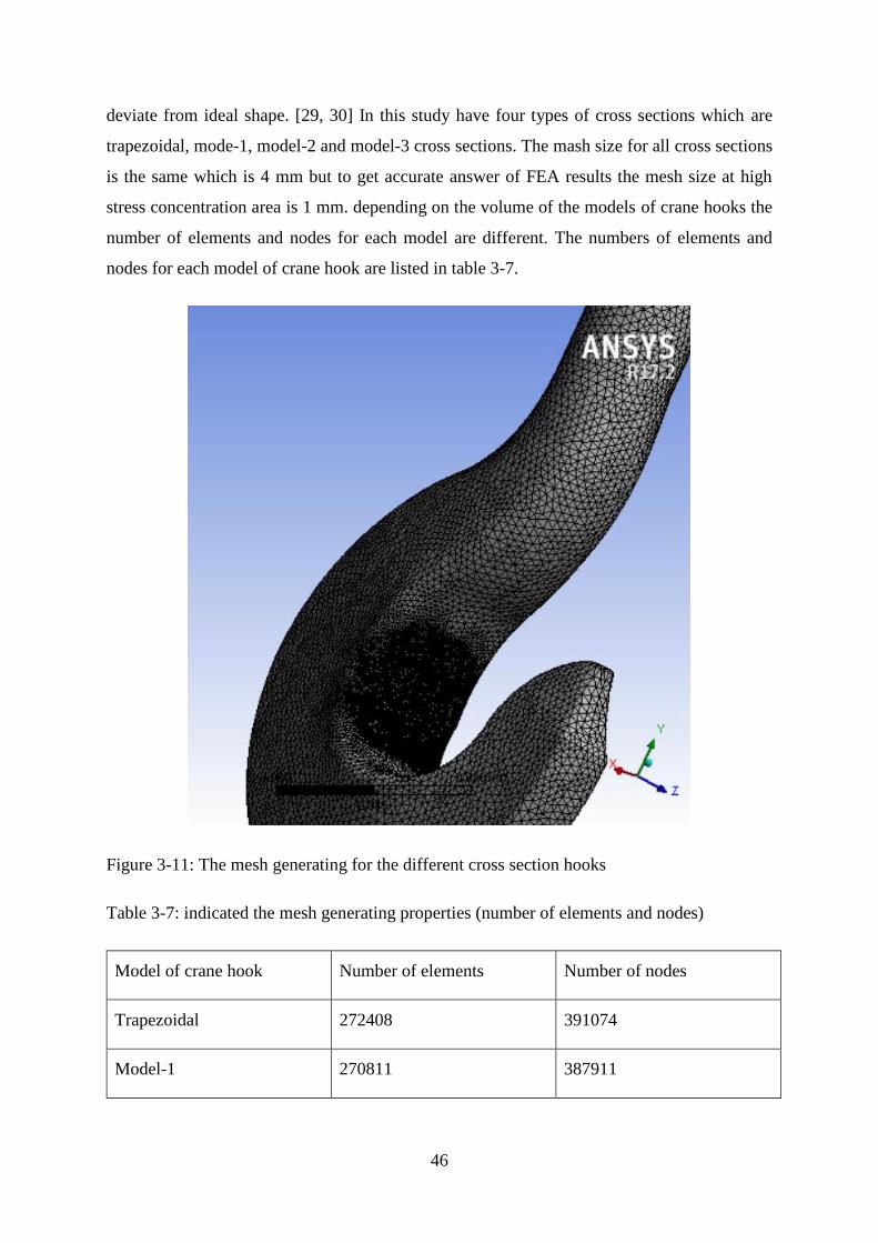
46
deviate from ideal shape. [29, 30] In this study have four types of cross sections which are
trapezoidal, mode-1, model-2 and model-3 cross sections. The mash size for all cross sections
is the same which is 4 mm but to get accurate answer of FEA results the mesh size at high
stress concentration area is 1 mm. depending on the volume of the models of crane hooks the
number of elements and nodes for each model are different. The numbers of elements and
nodes for each model of crane hook are listed in table 3-7.
Figure 3-11: The mesh generating for the different cross section hooks
Table 3-7: indicated the mesh generating properties (number of elements and nodes)
Model of crane hook Number of elements Number of nodes
Trapezoidal 272408 391074
Model-1 270811 387911
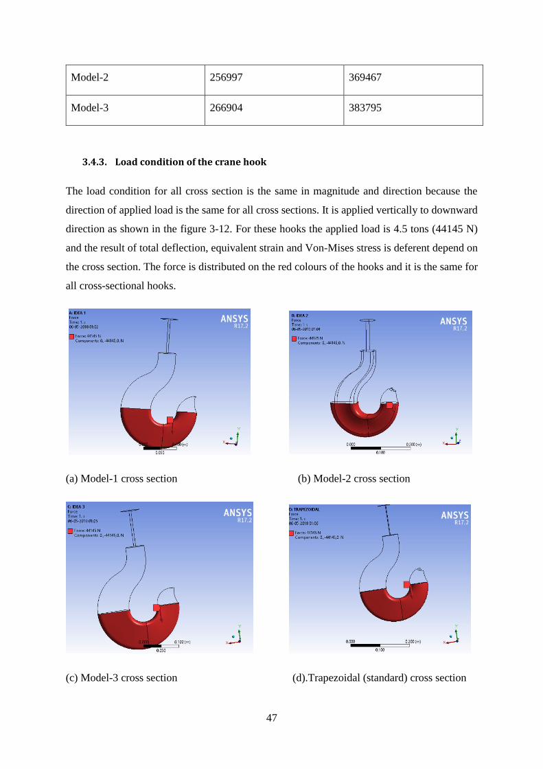
47
Model-2 256997 369467
Model-3 266904 383795
3.4.3. Load condition of the crane hook
The load condition for all cross section is the same in magnitude and direction because the
direction of applied load is the same for all cross sections. It is applied vertically to downward
direction as shown in the figure 3-12. For these hooks the applied load is 4.5 tons (44145 N)
and the result of total deflection, equivalent strain and Von-Mises stress is deferent depend on
the cross section. The force is distributed on the red colours of the hooks and it is the same for
all cross-sectional hooks.
(a) Model-1 cross section (b) Model-2 cross section
(c) Model-3 cross section (d).Trapezoidal (standard) cross section
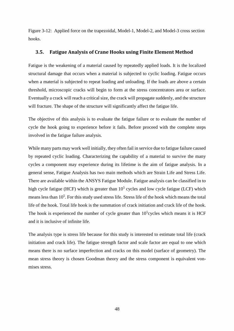
48
Figure 3-12: Applied force on the trapezoidal, Model-1, Model-2, and Model-3 cross section
hooks.
3.5. Fatigue Analysis of Crane Hooks using Finite Element Method
Fatigue is the weakening of a material caused by repeatedly applied loads. It is the localized
structural damage that occurs when a material is subjected to cyclic loading. Fatigue occurs
when a material is subjected to repeat loading and unloading. If the loads are above a certain
threshold, microscopic cracks will begin to form at the stress concentrators area or surface.
Eventually a crack will reach a critical size, the crack will propagate suddenly, and the structure
will fracture. The shape of the structure will significantly affect the fatigue life.
The objective of this analysis is to evaluate the fatigue failure or to evaluate the number of
cycle the hook going to experience before it fails. Before proceed with the complete steps
involved in the fatigue failure analysis.
While many parts may work well initially, they often fail in service due to fatigue failure caused
by repeated cyclic loading. Characterizing the capability of a material to survive the many
cycles a component may experience during its lifetime is the aim of fatigue analysis. In a
general sense, Fatigue Analysis has two main methods which are Strain Life and Stress Life.
There are available within the ANSYS Fatigue Module. Fatigue analysis can be classified in to
high cycle fatigue (HCF) which is greater than 105 cycles and low cycle fatigue (LCF) which
means less than 105. For this study used stress life. Stress life of the hook which means the total
life of the hook. Total life hook is the summation of crack initiation and crack life of the hook.
The hook is experienced the number of cycle greater than 105cycles which means it is HCF
and it is inclusive of infinite life.
The analysis type is stress life because for this study is interested to estimate total life (crack
initiation and crack life). The fatigue strength factor and scale factor are equal to one which
means there is no surface imperfection and cracks on this model (surface of geometry). The
mean stress theory is chosen Goodman theory and the stress component is equivalent von-
mises stress.
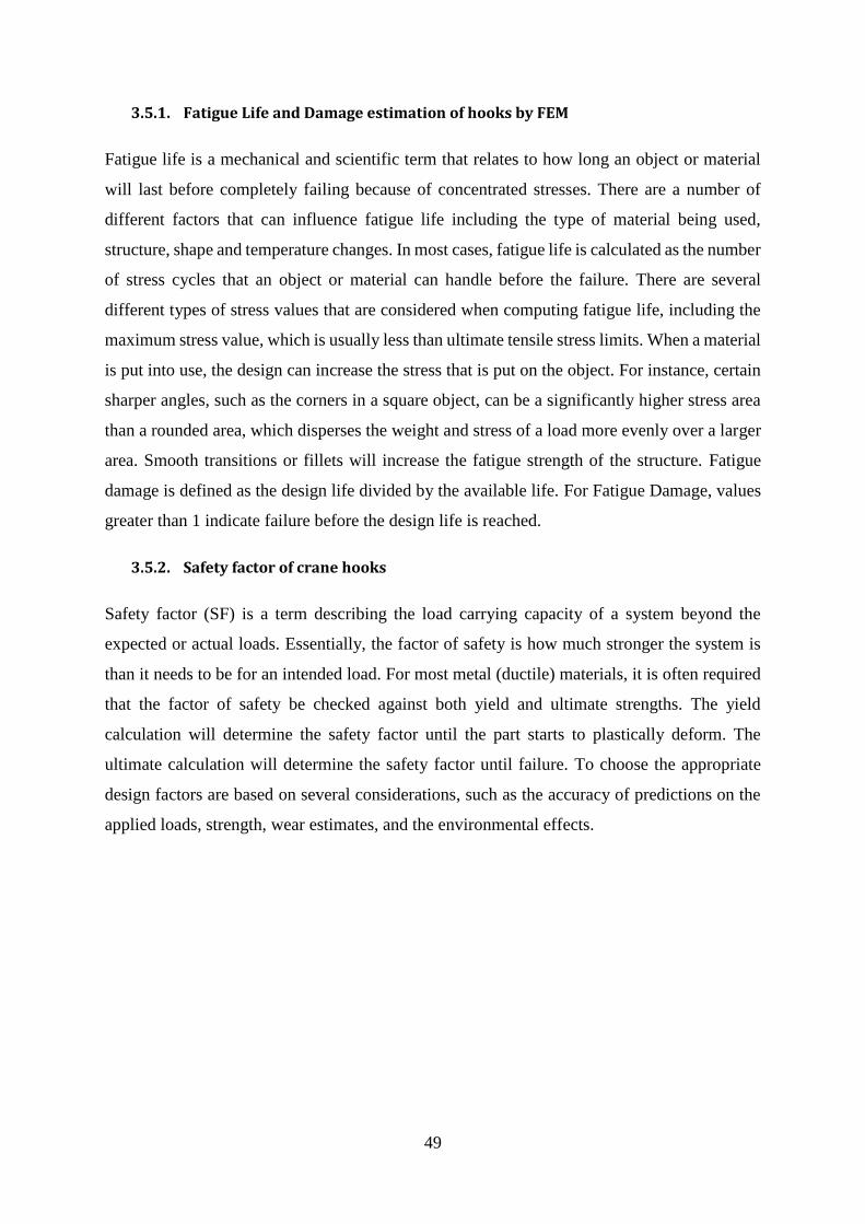
49
3.5.1. Fatigue Life and Damage estimation of hooks by FEM
Fatigue life is a mechanical and scientific term that relates to how long an object or material
will last before completely failing because of concentrated stresses. There are a number of
different factors that can influence fatigue life including the type of material being used,
structure, shape and temperature changes. In most cases, fatigue life is calculated as the number
of stress cycles that an object or material can handle before the failure. There are several
different types of stress values that are considered when computing fatigue life, including the
maximum stress value, which is usually less than ultimate tensile stress limits. When a material
is put into use, the design can increase the stress that is put on the object. For instance, certain
sharper angles, such as the corners in a square object, can be a significantly higher stress area
than a rounded area, which disperses the weight and stress of a load more evenly over a larger
area. Smooth transitions or fillets will increase the fatigue strength of the structure. Fatigue
damage is defined as the design life divided by the available life. For Fatigue Damage, values
greater than 1 indicate failure before the design life is reached.
3.5.2. Safety factor of crane hooks
Safety factor (SF) is a term describing the load carrying capacity of a system beyond the
expected or actual loads. Essentially, the factor of safety is how much stronger the system is
than it needs to be for an intended load. For most metal (ductile) materials, it is often required
that the factor of safety be checked against both yield and ultimate strengths. The yield
calculation will determine the safety factor until the part starts to plastically deform. The
ultimate calculation will determine the safety factor until failure. To choose the appropriate
design factors are based on several considerations, such as the accuracy of predictions on the
applied loads, strength, wear estimates, and the environmental effects.
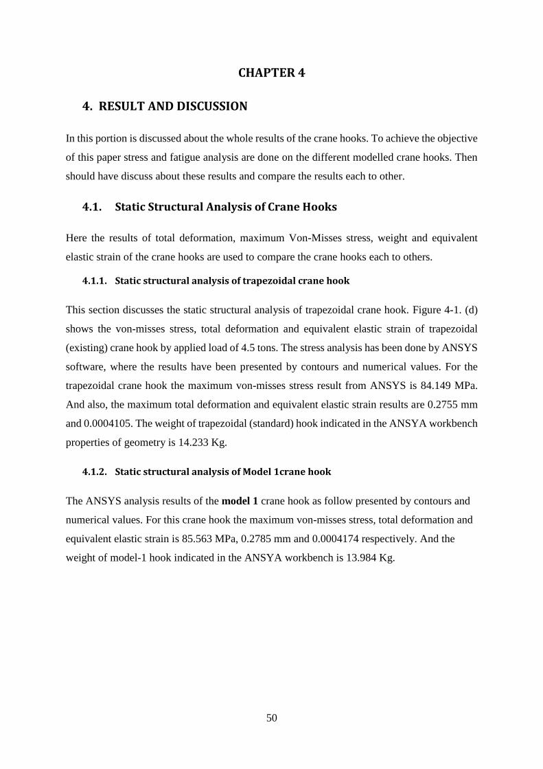
50
CHAPTER 4
4. RESULT AND DISCUSSION
In this portion is discussed about the whole results of the crane hooks. To achieve the objective
of this paper stress and fatigue analysis are done on the different modelled crane hooks. Then
should have discuss about these results and compare the results each to other.
4.1. Static Structural Analysis of Crane Hooks
Here the results of total deformation, maximum Von-Misses stress, weight and equivalent
elastic strain of the crane hooks are used to compare the crane hooks each to others.
4.1.1. Static structural analysis of trapezoidal crane hook
This section discusses the static structural analysis of trapezoidal crane hook. Figure 4-1. (d)
shows the von-misses stress, total deformation and equivalent elastic strain of trapezoidal
(existing) crane hook by applied load of 4.5 tons. The stress analysis has been done by ANSYS
software, where the results have been presented by contours and numerical values. For the
trapezoidal crane hook the maximum von-misses stress result from ANSYS is 84.149 MPa.
And also, the maximum total deformation and equivalent elastic strain results are 0.2755 mm
and 0.0004105. The weight of trapezoidal (standard) hook indicated in the ANSYA workbench
properties of geometry is 14.233 Kg.
4.1.2. Static structural analysis of Model 1crane hook
The ANSYS analysis results of the model 1 crane hook as follow presented by contours and
numerical values. For this crane hook the maximum von-misses stress, total deformation and
equivalent elastic strain is 85.563 MPa, 0.2785 mm and 0.0004174 respectively. And the
weight of model-1 hook indicated in the ANSYA workbench is 13.984 Kg.
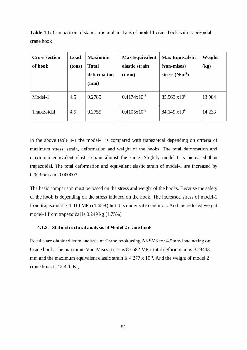
51
Table 4-1: Comparison of static structural analysis of model 1 crane hook with trapezoidal
crane hook
Cross section
of hook
Load
(tons)
Maximum
Total
deformation
(mm)
Max Equivalent
elastic strain
(m/m)
Max Equivalent
(von-mises)
stress (N/m2)
Weight
(kg)
Model-1 4.5 0.2785 0.4174x10⁻³ 85.563 x10⁶ 13.984
Trapizoidal 4.5 0.2755 0.4105x10⁻³ 84.149 x10⁶ 14.233
In the above table 4-1 the model-1 is compared with trapezoidal depending on criteria of
maximum stress, strain, deformation and weight of the hooks. The total deformation and
maximum equivalent elastic strain almost the same. Slightly model-1 is increased than
trapezoidal. The total deformation and equivalent elastic strain of model-1 are increased by
0.003mm and 0.000007.
The basic comparison must be based on the stress and weight of the hooks. Because the safety
of the hook is depending on the stress induced on the hook. The increased stress of model-1
from trapezoidal is 1.414 MPa (1.68%) but it is under safe condition. And the reduced weight
model-1 from trapezoidal is 0.249 kg (1.75%).
4.1.3. Static structural analysis of Model 2 crane hook
Results are obtained from analysis of Crane hook using ANSYS for 4.5tons load acting on
Crane hook. The maximum Von-Mises stress is 87.682 MPa, total deformation is 0.28443
mm and the maximum equivalent elastic strain is 4.277 x 10⁻⁴. And the weight of model 2
crane hook is 13.426 Kg.
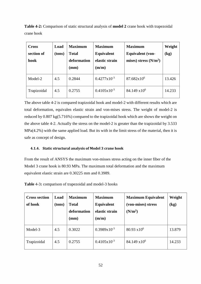
52
Table 4-2: Comparison of static structural analysis of model 2 crane hook with trapezoidal
crane hook
Cross
section of
hook
Load
(tons)
Maximum
Total
deformation
(mm)
Maximum
Equivalent
elastic strain
(m/m)
Maximum
Equivalent (von-
mises) stress (N/m2)
Weight
(kg)
Model-2 4.5 0.2844 0.4277x10⁻³ 87.682x10⁶ 13.426
Trapizoidal 4.5 0.2755 0.4105x10⁻³ 84.149 x10⁶ 14.233
The above table 4-2 is compared trapizoidal hook and model-2 with different results which are
total deformation, equivalen elastic strain and von-mises stress. The weight of model-2 is
reduced by 0.807 kg(5.716%) compared to the trapizoidal hook which are shows the weight on
the above table 4-2. Actually the stress on the model-2 is greater than the trapizoidal by 3.533
MPa(4.2%) with the same applied load. But its with in the limit stress of the material, then it is
safe as concept of design.
4.1.4. Static structural analysis of Model 3 crane hook
From the result of ANSYS the maximum von-misses stress acting on the inner fiber of the
Model 3 crane hook is 80.93 MPa. The maximum total deformation and the maximum
equivalent elastic strain are 0.30225 mm and 0.3989.
Table 4-3: comparison of trapezoidal and model-3 hooks
Cross section
of hook
Load
(tons)
Maximum
Total
deformation
(mm)
Maximum
Equivalent
elastic strain
(m/m)
Maximum Equivalent
(von-mises) stress
(N/m2)
Weight
(kg)
Model-3 4.5 0.3022 0.3989x10⁻³ 80.93 x10⁶ 13.879
Trapizoidal 4.5 0.2755 0.4105x10⁻³ 84.149 x10⁶ 14.233
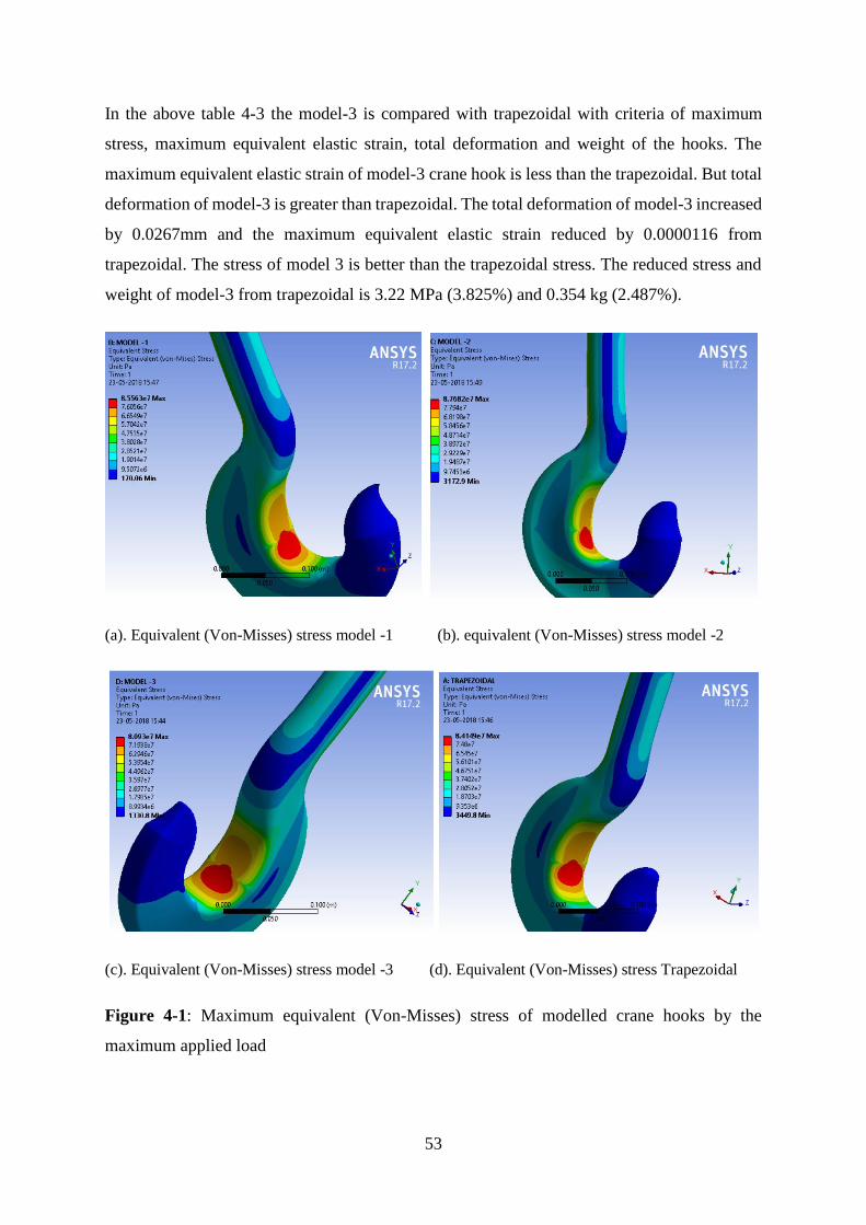
53
In the above table 4-3 the model-3 is compared with trapezoidal with criteria of maximum
stress, maximum equivalent elastic strain, total deformation and weight of the hooks. The
maximum equivalent elastic strain of model-3 crane hook is less than the trapezoidal. But total
deformation of model-3 is greater than trapezoidal. The total deformation of model-3 increased
by 0.0267mm and the maximum equivalent elastic strain reduced by 0.0000116 from
trapezoidal. The stress of model 3 is better than the trapezoidal stress. The reduced stress and
weight of model-3 from trapezoidal is 3.22 MPa (3.825%) and 0.354 kg (2.487%).
(a). Equivalent (Von-Misses) stress model -1 (b). equivalent (Von-Misses) stress model -2
(c). Equivalent (Von-Misses) stress model -3 (d). Equivalent (Von-Misses) stress Trapezoidal
Figure 4-1: Maximum equivalent (Von-Misses) stress of modelled crane hooks by the
maximum applied load
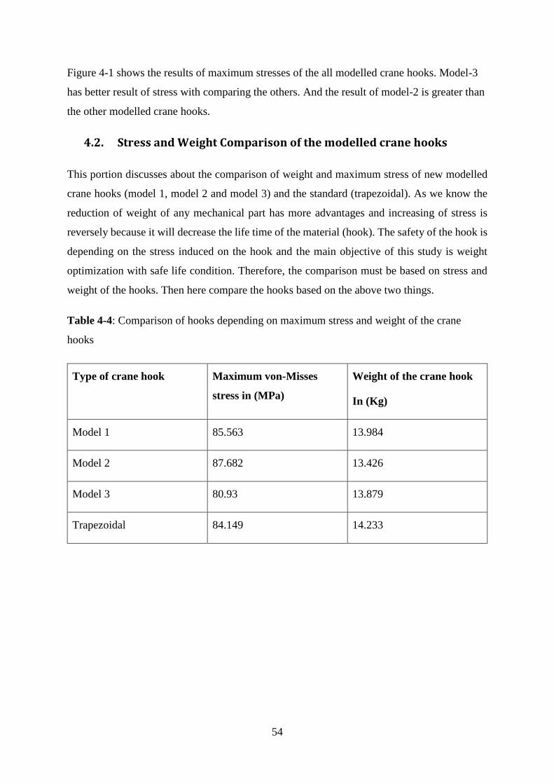
54
Figure 4-1 shows the results of maximum stresses of the all modelled crane hooks. Model-3
has better result of stress with comparing the others. And the result of model-2 is greater than
the other modelled crane hooks.
4.2. Stress and Weight Comparison of the modelled crane hooks
This portion discusses about the comparison of weight and maximum stress of new modelled
crane hooks (model 1, model 2 and model 3) and the standard (trapezoidal). As we know the
reduction of weight of any mechanical part has more advantages and increasing of stress is
reversely because it will decrease the life time of the material (hook). The safety of the hook is
depending on the stress induced on the hook and the main objective of this study is weight
optimization with safe life condition. Therefore, the comparison must be based on stress and
weight of the hooks. Then here compare the hooks based on the above two things.
Table 4-4: Comparison of hooks depending on maximum stress and weight of the crane
hooks
Type of crane hook Maximum von-Misses
stress in (MPa)
Weight of the crane hook
In (Kg)
Model 1 85.563 13.984
Model 2 87.682 13.426
Model 3 80.93 13.879
Trapezoidal 84.149 14.233
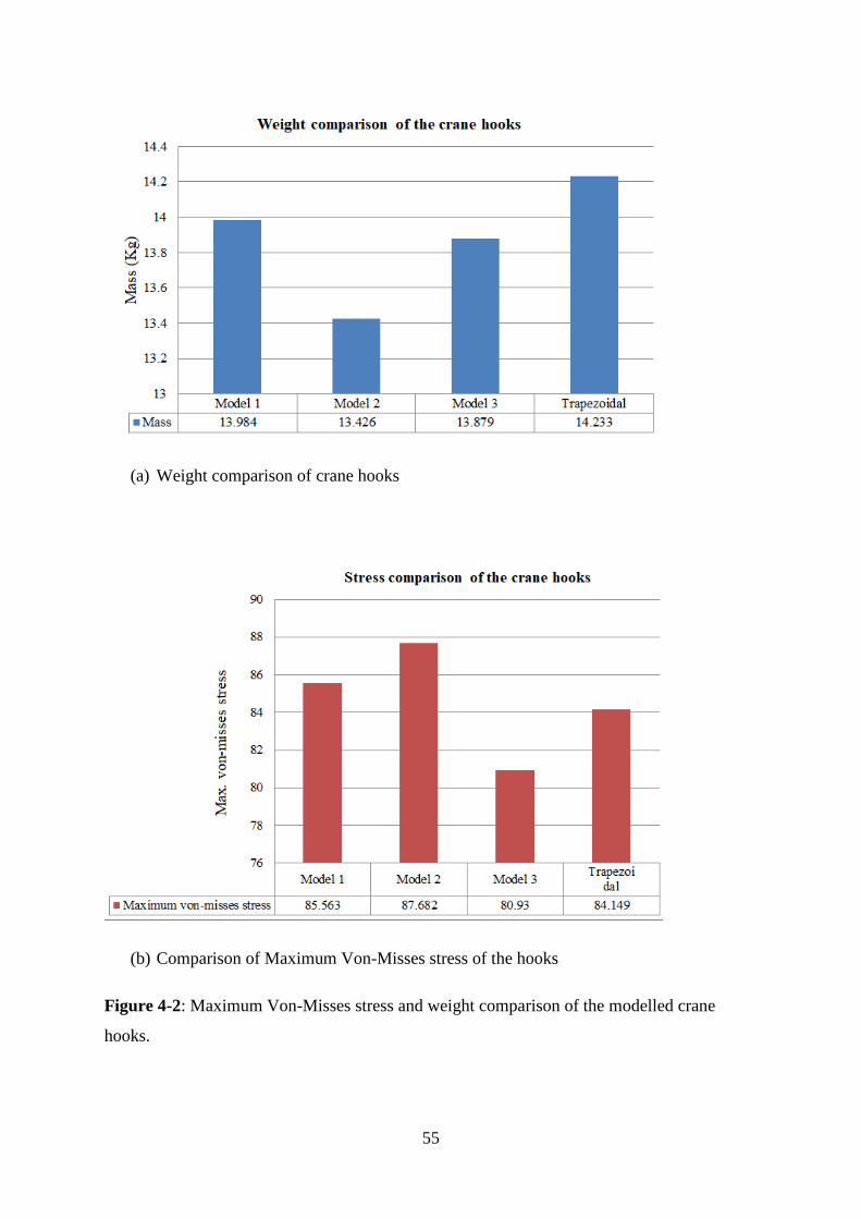
55
(a) Weight comparison of crane hooks
(b) Comparison of Maximum Von-Misses stress of the hooks
Figure 4-2: Maximum Von-Misses stress and weight comparison of the modelled crane
hooks.
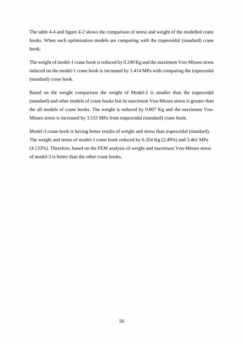
56
The table 4-4 and figure 4-2 shows the comparison of stress and weight of the modelled crane
hooks. When each optimization models are comparing with the trapezoidal (standard) crane
hook;
The weight of model-1 crane hook is reduced by 0.249 Kg and the maximum Von-Misses stress
induced on the model-1 crane hook is increased by 1.414 MPa with comparing the trapezoidal
(standard) crane hook.
Based on the weight comparison the weight of Model-2 is smaller than the trapezoidal
(standard) and other models of crane hooks but its maximum Von-Misses stress is greater than
the all models of crane hooks. The weight is reduced by 0.807 Kg and the maximum Von-
Misses stress is increased by 3.533 MPa from trapezoidal (standard) crane hook.
Model-3 crane hook is having better results of weight and stress than trapezoidal (standard).
The weight and stress of model-3 crane hook reduced by 0.354 Kg (2.49%) and 3.461 MPa
(4.133%). Therefore, based on the FEM analysis of weight and maximum Von-Misses stress
of model-3 is better than the other crane hooks.
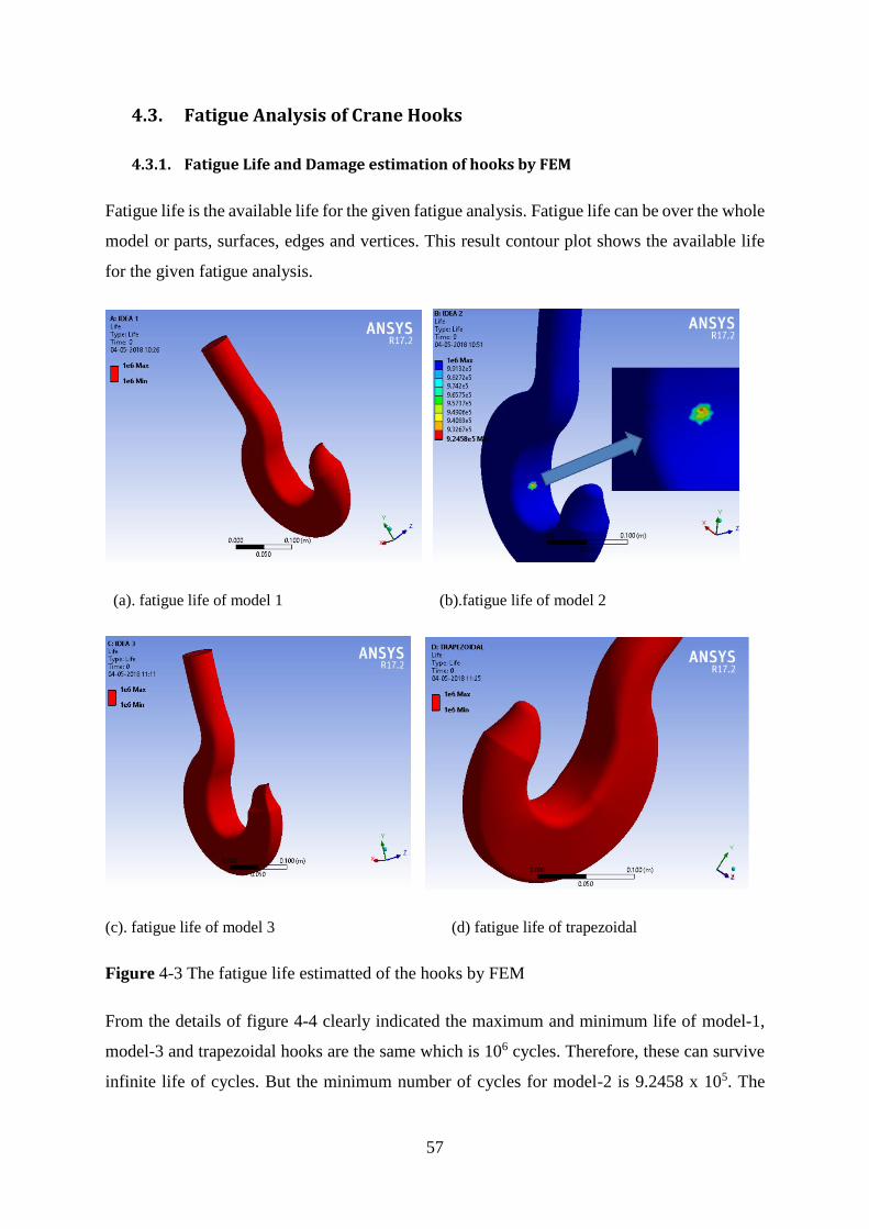
57
4.3. Fatigue Analysis of Crane Hooks
4.3.1. Fatigue Life and Damage estimation of hooks by FEM
Fatigue life is the available life for the given fatigue analysis. Fatigue life can be over the whole
model or parts, surfaces, edges and vertices. This result contour plot shows the available life
for the given fatigue analysis.
(a). fatigue life of model 1 (b).fatigue life of model 2
(c). fatigue life of model 3 (d) fatigue life of trapezoidal
Figure 4-3 The fatigue life estimatted of the hooks by FEM
From the details of figure 4-4 clearly indicated the maximum and minimum life of model-1,
model-3 and trapezoidal hooks are the same which is 106 cycles. Therefore, these can survive
infinite life of cycles. But the minimum number of cycles for model-2 is 9.2458 x 10⁵. The
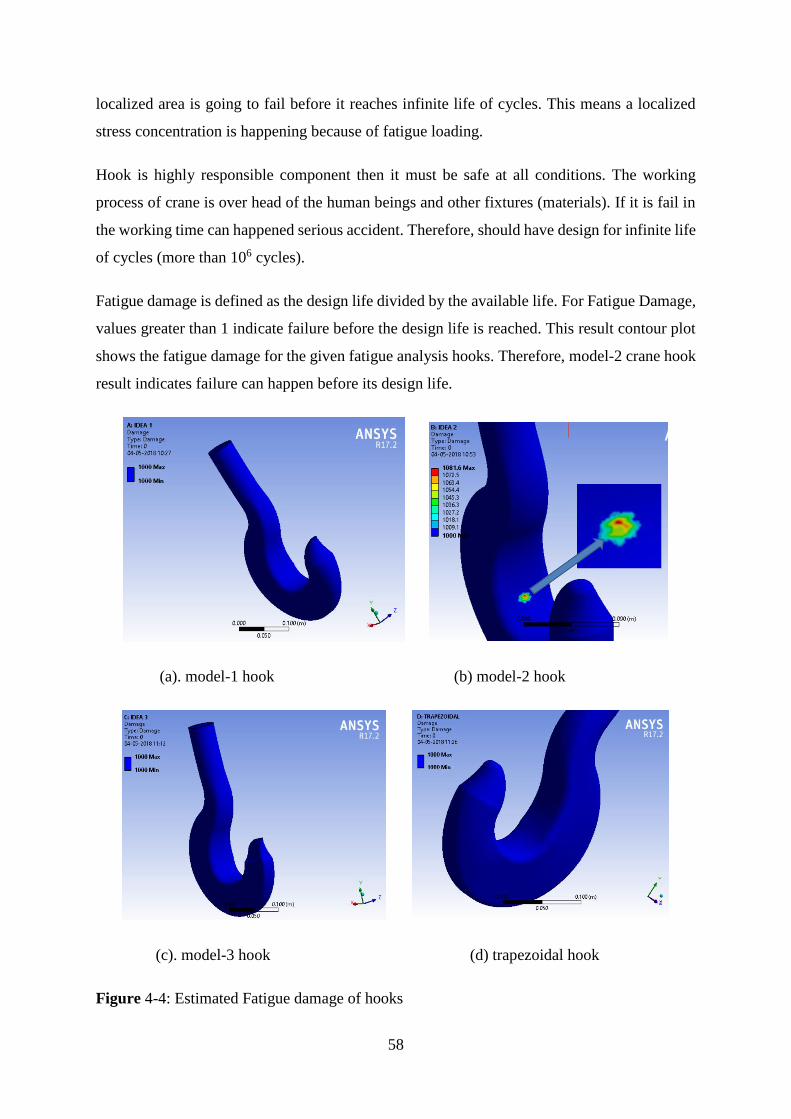
58
localized area is going to fail before it reaches infinite life of cycles. This means a localized
stress concentration is happening because of fatigue loading.
Hook is highly responsible component then it must be safe at all conditions. The working
process of crane is over head of the human beings and other fixtures (materials). If it is fail in
the working time can happened serious accident. Therefore, should have design for infinite life
of cycles (more than 106 cycles).
Fatigue damage is defined as the design life divided by the available life. For Fatigue Damage,
values greater than 1 indicate failure before the design life is reached. This result contour plot
shows the fatigue damage for the given fatigue analysis hooks. Therefore, model-2 crane hook
result indicates failure can happen before its design life.
(a). model-1 hook (b) model-2 hook
(c). model-3 hook (d) trapezoidal hook
Figure 4-4: Estimated Fatigue damage of hooks
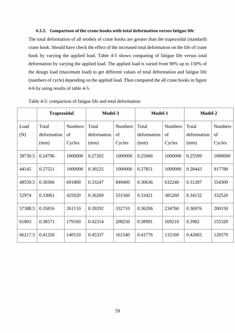
59
4.3.2. Comparison of the crane hooks with total deformation verses fatigue life
The total deformation of all models of crane hooks are greater than the trapezoidal (standard)
crane hook. Should have check the effect of the increased total deformation on the life of crane
hook by varying the applied load. Table 4-5 shows comparing of fatigue life versus total
deformation by varying the applied load. The applied load is varied from 90% up to 150% of
the design load (maximum load) to get different values of total deformation and fatigue life
(numbers of cycle) depending on the applied load. Then compared the all crane hooks in figure
4-6 by using results of table 4-5.
Table 4-5: comparison of fatigue life and total deformation
Trapezoidal Model-3 Model-1 Model-2
Load
(N)
Total
deformation
(mm)
Numbers
of
Cycles
Total
deformation
(mm)
Numbers
of
Cycles
Total
deformation
(mm)
Numbers
of
Cycles
Total
deformation
(mm)
Numbers
of
Cycles
39730.5 0.24796 1000000 0.27202 1000000 0.25066 1000000 0.25599 1000000
44145 0.27551 1000000 0.30225 1000000 0.27851 1000000 0.28443 917780
48559.5 0.30306 691800 0.33247 849400 0.30636 632240 0.31287 554300
52974 0.33061 425020 0.36269 531560 0.33421 385260 0.34132 332520
57388.5 0.35816 261110 0.39292 332710 0.36206 234760 0.36976 200150
61803 0.38571 179160 0.42314 208250 0.38991 169210 0.3982 155320
66217.5 0.41326 140510 0.45337 161540 0.41776 132160 0.42665 120570
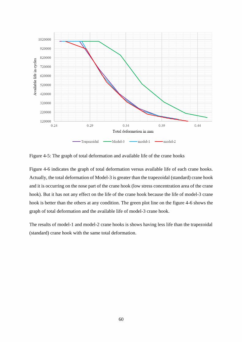
60
Figure 4-5: The graph of total deformation and available life of the crane hooks
Figure 4-6 indicates the graph of total deformation versus available life of each crane hooks.
Actually, the total deformation of Model-3 is greater than the trapezoidal (standard) crane hook
and it is occurring on the nose part of the crane hook (low stress concentration area of the crane
hook). But it has not any effect on the life of the crane hook because the life of model-3 crane
hook is better than the others at any condition. The green plot line on the figure 4-6 shows the
graph of total deformation and the available life of model-3 crane hook.
The results of model-1 and model-2 crane hooks is shows having less life than the trapezoidal
(standard) crane hook with the same total deformation.
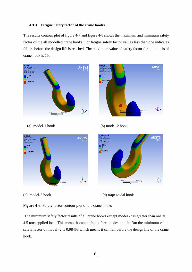
61
4.3.3. Fatigue Safety factor of the crane hooks
The results contour plot of figure 4-7 and figure 4-8 shows the maximum and minimum safety
factor of the all modelled crane hooks. For fatigue safety factor values less than one indicates
failure before the design life is reached. The maximum value of safety factor for all models of
crane hook is 15.
(a). model-1 hook (b) model-2 hook
(c). model-3 hook (d) trapezoidal hook
Figure 4-6: Safety factor contour plot of the crane hooks
The minimum safety factor results of all crane hooks except model -2 is greater than one at
4.5 tons applied load. This means it cannot fail before the design life. But the minimum value
safety factor of model -2 is 0.98453 which means it can fail before the design life of the crane
hook.
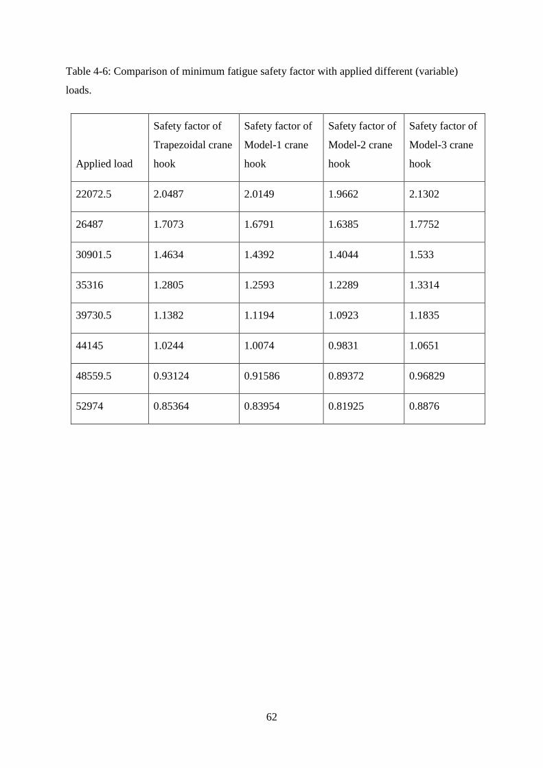
62
Table 4-6: Comparison of minimum fatigue safety factor with applied different (variable)
loads.
Applied load
Safety factor of
Trapezoidal crane
hook
Safety factor of
Model-1 crane
hook
Safety factor of
Model-2 crane
hook
Safety factor of
Model-3 crane
hook
22072.5 2.0487 2.0149 1.9662 2.1302
26487 1.7073 1.6791 1.6385 1.7752
30901.5 1.4634 1.4392 1.4044 1.533
35316 1.2805 1.2593 1.2289 1.3314
39730.5 1.1382 1.1194 1.0923 1.1835
44145 1.0244 1.0074 0.9831 1.0651
48559.5 0.93124 0.91586 0.89372 0.96829
52974 0.85364 0.83954 0.81925 0.8876
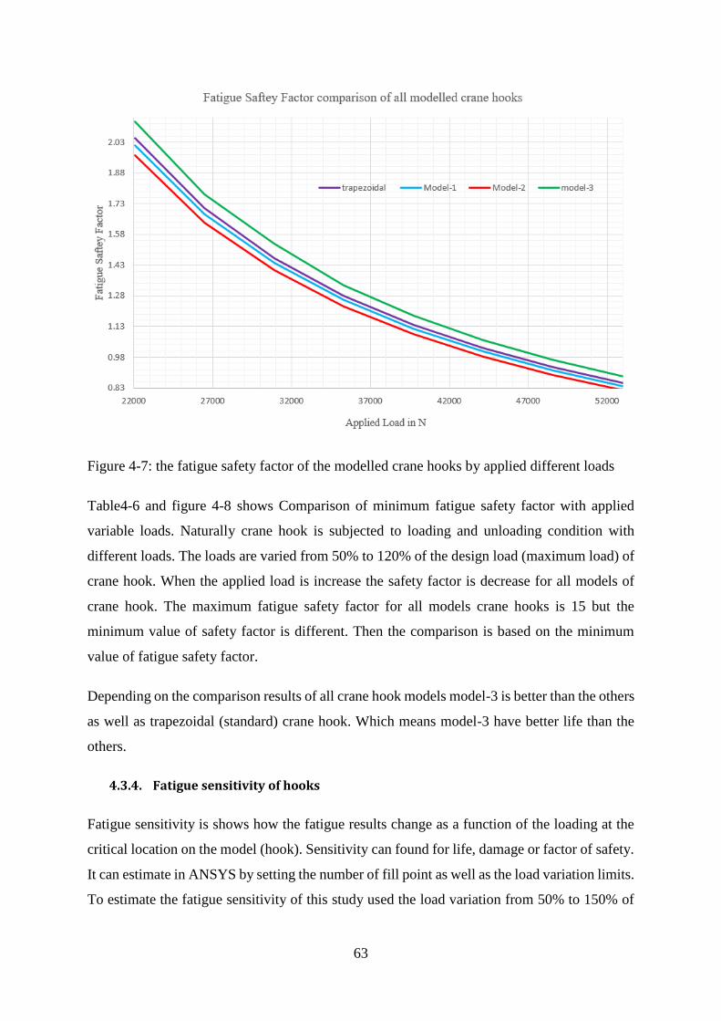
63
Figure 4-7: the fatigue safety factor of the modelled crane hooks by applied different loads
Table4-6 and figure 4-8 shows Comparison of minimum fatigue safety factor with applied
variable loads. Naturally crane hook is subjected to loading and unloading condition with
different loads. The loads are varied from 50% to 120% of the design load (maximum load) of
crane hook. When the applied load is increase the safety factor is decrease for all models of
crane hook. The maximum fatigue safety factor for all models crane hooks is 15 but the
minimum value of safety factor is different. Then the comparison is based on the minimum
value of fatigue safety factor.
Depending on the comparison results of all crane hook models model-3 is better than the others
as well as trapezoidal (standard) crane hook. Which means model-3 have better life than the
others.
4.3.4. Fatigue sensitivity of hooks
Fatigue sensitivity is shows how the fatigue results change as a function of the loading at the
critical location on the model (hook). Sensitivity can found for life, damage or factor of safety.
It can estimate in ANSYS by setting the number of fill point as well as the load variation limits.
To estimate the fatigue sensitivity of this study used the load variation from 50% to 150% of
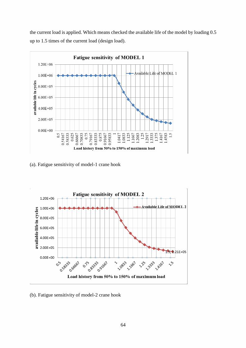
64
the current load is applied. Which means checked the available life of the model by loading 0.5
up to 1.5 times of the current load (design load).
(a). Fatigue sensitivity of model-1 crane hook
(b). Fatigue sensitivity of model-2 crane hook
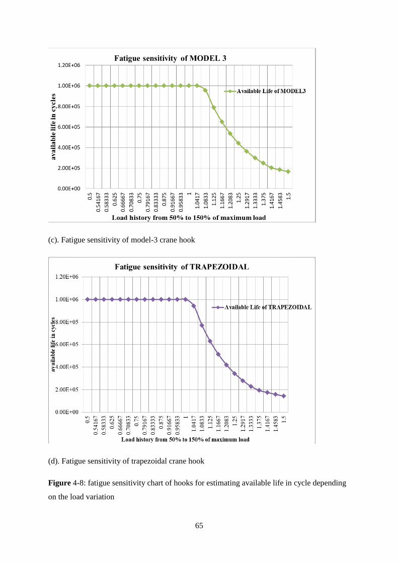
65
(c). Fatigue sensitivity of model-3 crane hook
(d). Fatigue sensitivity of trapezoidal crane hook
Figure 4-8: fatigue sensitivity chart of hooks for estimating available life in cycle depending
on the load variation
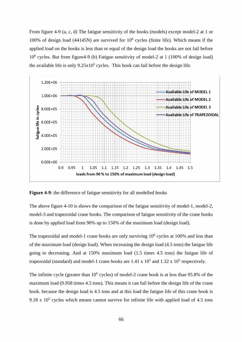
66
From figure 4-9 (a, c, d) The fatigue sensitivity of the hooks (models) except model-2 at 1 or
100% of design load (44145N) are survived for 106 cycles (finite life). Which means if the
applied load on the hooks is less than or equal of the design load the hooks are not fail before
106 cycles. But from figure4-9 (b) Fatigue sensitivity of model-2 at 1 (100% of design load)
the available life is only 9.25x10⁵ cycles. This hook can fail before the design life.
Figure 4-9: the difference of fatigue sensitivity for all modelled hooks
The above figure 4-10 is shows the comparison of the fatigue sensitivity of model-1, model-2,
model-3 and trapezoidal crane hooks. The comparison of fatigue sensitivity of the crane hooks
is done by applied load from 90% up to 150% of the maximum load (design load).
The trapezoidal and model-1 crane hooks are only surviving 106 cycles at 100% and less than
of the maximum load (design load). When increasing the design load (4.5 tons) the fatigue life
going to decreasing. And at 150% maximum load (1.5 times 4.5 tons) the fatigue life of
trapezoidal (standard) and model-1 crane hooks are 1.41 x 10⁵ and 1.32 x 10⁵ respectively.
The infinite cycle (greater than 106 cycles) of model-2 crane hook is at less than 95.8% of the
maximum load (0.958 times 4.5 tons). This means it can fail before the design life of the crane
hook. because the design load is 4.5 tons and at this load the fatigue life of this crane hook is
9.18 x 10⁵ cycles which means cannot survive for infinite life with applied load of 4.5 tons

67
(design load). At 150% of maximum load (1.5 times 4.5 tons) model-2 crane hook can survive
only 1.21 x 10⁵ cycles.
Model-3 crane hook can survive the infinite life (above 106 cycles) up to 106% of maximum
load (design load). This means the fatigue life of this crane hook is 106 and above cycles until
the applied load greater than 1.06 times 4.5 tons (4.77 tons). At 150% of the maximum load
(1.5 times 4.5 tons) the fatigue life of this crane hook is 1.62 x 10⁵ cycles. The design of all
models of crane hooks is considered to survive infinite life up to the applied load is 4.5 tons
and less than, but model-3 crane hook is surviving infinite life up to applied load is reaches
4.77 tons.
The fatigue life model-3 crane hook is better than the other models and trapezoidal (standard)
crane hooks at all conditions. Therefore, depend on the fatigue sensitivity model 3 crane hook
is better than the other crane hook.
68
CHAPTER 5
5. CONCLUSION, RECOMMENDATION AND FUTURE WORKS
5.1. Conclusion
To conclude the results of each modified modelling crane hooks with the standard crane hook,
the maximum Von-Misses stress and total deformation of model -1 and model -2 are increased.
The fatigue life of both model-1 and model-2 crane hook is less than the standard crane hook.
The maximum Von-Misses stress of model -3 is reduced and total deformation is increased.
The fatigue life of model-3 crane hook is greater than the standard crane hook. Then model-3
crane hook has been selected as a best crane hook model.
From model-3 crane hook analysis get the following result which is achieved the objective of
the thesis.
❖ The fatigue life of Model-3 crane hook is better than standard crane hook, and it is
increased by 22.78% from the standard crane hook
❖ The maximum stress of model-3 crane hook is reduced by 3.461 MPa (4.133%) from
the standard crane hook.
❖ The total deformation induced on model-3 crane hook is greater than the standard crane
hook by 0.035 mm. But the increased value is very small with comparing the overall
dimension of the crane hook. And it has no effect on the life of the crane hook, because
still life of model-3 is better than standard crane hook at any applied load.
❖ The weight of model-3 crane hook is reduced by 0.354 Kg (2.487%) from the standard
crane hook. This means the mass and volume of the crane hook is optimized.
Therefore model-3 crane hook is considered as optimized result.
69
5.2. Recommendation and Future works
In this thesis work stress and weight optimization is studied for different cross sectional crane
hooks using finite element method (FEM). Now the Finite element method is widely used for
mechanical analysis. Using FEM for stress analysis, weight optimization and fatigue life
estimation have the many advantages. Some of these advantages are requiring a short period
of time for analysis and less cost as compared to the experimental method.
The literature review allows Related to this title are very few articles have been published so
need more extensive investigation on optimization of crane hook using geometrical
modification. However, this paper can be extended to weight and stress optimization by varying
radius of curvature of the crane hook. And also can be study about thermal analysis of crane
hook.
70
REFERENCE
1. K. Ashok Babu, D.V. Subba Rao, Dr. P H V Sesha Talpa Sai, “Design Optimization
and Contact Analysis on Dual Joint.” International Journal of Science, Engineering
and Technology Research, vol. 4, pp. 2485-2493, July 2015.
2. Mr. Y.S.Mundada, Mr. S.J.Parihar, “Review of Finite Element Analysis of Crane
Hook.” in proc. CONVERGENCE 2016, April 2016, pp. 378-381.
3. B. Nagaraju, M. RajaRoy, P. Venkatesh Reddy, K Satyanarayana, “Stress Analysis of
crane Hook Using FEA.” International Journal of Current Engineering and Scientific
Research, vol. 2, pp. 126-131, February 2015.
4. Zaiyi Pana, Hongling Guoa, Yan Lia, “Automated Method for Optimizing Feasible
Locations of Mobile Cranes Based on 3D Visualization” pp. 19-22 June 2017.
5. G.R.Dinesh, P.NaveenChandran, “Analysis of Crane Hook using ANSYS Simulation
Tool.” International Journal of Advances in Engineering, pp. 434-438, April 2015.
6. Dr. Daniel Kitaw, “Pulleys, Sprockets, Drums and Load Handling Attachements” in
Material Handling Equipment, Ed. Ethiopia: Addis Ababa University, 2001, pp.76-
80.
7. Vivek Mahadev Thakur, Vaibhav Pawar, Dr. M.D. Nadar, Sanjay Ghorpade, Sahil
Patil, “Study and Analysis of Crane Hook in Loading Area.” International Journal of
Advanced Research in Education & Technology, vol. 3, pp. 88-89, March 2016.
8. A. Gopichand, R. V. S. Lakshmi, B. Maheshkrishna “Optimization of design
parameter for crane hook using taguchi method.” International Journal of Innovative
Research in Science, Engineering and Technology, vol.2, pp. 7780-7784, December
2013.
9. Nishant soni, “crane-hook shapes optimization and thermal analysis using finite
element too.” IJAIR, PP. 51-55, 2013.
10. Rasmi Uddanwadikar “Stress Analysis of Crane Hook and Validation by Photo-
Elasticity.” Scientific Research, pp. 935-941, August 2011.
71
11. Pradyumnakesharimaharana, “Computer Aided Analysis and Design of Hoisting
Mechanism of an EOT Crane.” Thesis, National Institute of Technology Rourkela,
May 2012.
12. M. Shaban, M. I. Mohamed, A. E. Abuelezz and T. Khalifa, “Determination of Stress
Distribution in Crane Hook by Caustic.” International Journal of Innovative
Research in Science, Engineering and Technology, vol. 2, pp. 1834-1840, May 2013.
13. Patel A.K, Jani V.K, “Design and Dynamic Analysis of 70T Double Girder Electrical
Overhead Crane.” Journal of Information, Knowledge and Research in Mechanical
Engineering, vol. 2, pp. 496-503, October 2013.
14. Takuma Nishimura, Takao Muromaki, Kazuyuki Hanahara, “Damage factor
Estimation of Crane Hook (A database approach with Image, Knowledge and
simulation),” in pro. 4th International Workshop on Reliable Engineering Computing,
2010, pp. 623-632.
15. Santosh Sahu, Ritesh Dewangan, Manas Patnaik, Narendra Yadav,“Study of Crane
Hook Having Trapezoidal Section by Finite Element Method& Design Experiments.”
International Journal of Modern Engineering Research, vol. 2, pp. 2779-2781,
August 2012.
16. Chetan N. Benkar, Dr. N. A. Wankhade “Finite Element Stress Analysis of Crane
Hook with Different Cross Sections.” International Journal for Technological
Research in Engineering, vol. 1, pp. 868-872, May 2014.
17. E.Narvydas, N.Puodziuniene, “Circumferential Stress Concentration Factor at the
Asymmetric shallow Notches of The lifting hook of trapezoidal cross-section.” vol.
18, pp. 152-157, April 2012.
18. Yogesh Tripathi, K. Joshi, “Comparison between Winker-Batch Theory and Finite
Element Method in Crane Hook for Trapezoidal Cross- Sectional Area.” International
Journal of Research in Engineering and Technology, vol. 2, pp. 26-31, September
2013.
72
19. Y. Torres, J.M. Gallardo, J. Dominguez, F.J. Jiménez E, “Brittle fracture of a crane
hook.” ScienceDirect, engineering failure Analysis, vol. 17, pp. 38-47, 30 December
2008.
20. Apichit Manee-ngam, Penyarat Saisirirat, Patpimol Suwankan, “hook design loading
by the optimization method with weighted factors rating method.” In proc. AEDCEE,
25-26 May 2017, PP. 337-342.
21. Mahesh Solanki, Antriksh Bhatt, Anilkumar Rathour, “Design, Analysis and Weight
Optimization of Crane Hook: A Review.” International Journal for Scientific
Research & Development, vol. 2, pp. 124-127, September 2014.
22. J.D. Costa, J.M. Ferreira, A.L. Ramalho, “Fatigue and fretting fatigue of ion-nitrided
34CrNiMo6 steel.” ScienceDirect, Theoretical and Applied Fracture Mechanics, vol.
35, pp. 69-79, 2001.
23. Richard G. Budynas and J. Keith Nisbett, “Load and Stress Analysis” in Shigley’s
Mechanical Engineering Design, 9th ed., New York: McGraw - Hill Series in
Mechanical Engineering, 2011, pp. 118-122.
24. Abass Adeyinka, “Fatigue Failure and Testing Methods”, May 15th 2013.
25. ASM International, “fatigue” in Elements of Metallurgy and Engineering Alloys, F.C.
Campbell. Ed. 2008, pp. 243-246.
26. Professor Dan Dubina, “Advanced Design of steel and Composite
structures.Internet:https://www.ct.upt.ro/suscos/files/2013-2015/2C08/L6-
Fatigue%20of%20structures.pdf
27. Arthur J. McEvily, “Fatigue” in Metal Failures, Mechanisms, Analysis, Prevention.”
2nd Edition Canada: John Wiley & Sons, Inc., Hoboken, New Jersey, 2013, pp. 237-
246.
28. Mulugeta Habtemariam, “Fracture Analysis of Pressure Vessel under Dynamic
Loading and Thermal Effect”, June 24, 2009.
29. Marshall Bern, David Eppstein “Mesh Generation and Optimal Triangulation” Xerox
Palo Alto Research Center, Palo Alto, California, U.S.A., pp. 2-4.
73
30. Metin Ozen, “Meshing Workshop” Ozen Engineering, Inc, Publisher, November 13th,
2014.
31. Sampath S, Sawan Shetty, Chithirai Pon Selvan M. “Design and Validation of Hook
Used in Double Spring Balancer for the Suspension of Weight Using FEA
Technique.” International Journal of Energy Science and Engineering, vol. 1, pp.
141-147, July 2014.
32. Prashant R. Mali, Dr. K. Dhande “Design, Structural Analysis and Optimization of
Crane Hook.” International Engineering Research Journal, Issue 2, Pp. 4298-4302,
November, 2015.
33. Amandeep Singh, Vinod Rohilla, “Optimization and Fatigue Analysisof a Crane
Hook Using Finite Element Method.” International Journal of Recent advances in
Mechanical Engineering, vol. 4, pp. 31-43, November 2015.
34. Jayesh Rajendra Chopda, Prof. S. H. Mankar, “Design, Analysis and Optimization of
Electric Overhead Travelling Crane Hook.” International Journal of Modern Trends
in Engineering and Research, vol. 2, pp. 285-294, May 2015.
35. K. S. Raghu Ram, D. Ajay Kumar, “Stress Analysis of Traverse Beam Crane Hook
Used in Steel Melting Shops of Steel Plant by ANSYS and CATIA.” American
Journal of Mechanical and Industrial Engineering, vol. 2, pp. 37-40, January 2017.
36. Ejaj R. Khan, Vinayak S. Kardile, Pravin D. Dhakane, Akash P. Gore, Bhushan D.
Mahajan, “Design and Analysis of Crane Hook with Different Materials.”
International Journal of Innovative and Emerging Research in Engineering, vol. 4,
pp. 227-233, 2017.
37. Mamta R. Zade, “Finite Element Analysis and Fatigue Analysis of Crane Hook with
Different Materials.” International Research Journal of Engineering and Technology,
vol. 4, pp. 1429-1436, Jan 2017.
38. Prof. Kunjan B. Vanpariya, Prof. Vishal Pandya, Prof. Jayesh Koisha, “Design
Analysis and Weight Optimization of Lifting Hook.” Journal of Emerging
Technologies and Innovative Research, vol. 3, pp. 81-85, December 2016.
74
39. Mahesh Solanki, Antriksh Bhatt, Anilkumar Rathour, Smit Thakkar, “Weight
Optimization in Crane Hook.” IJRDO-Journal of Mechanical and Civil Engineering,
vol. 1, pp. 192-196, June 2015.
40. Sunil J. Tiwari, Vivek Padole, “Design, Analysis and Material Optimization of
Laminated Crane Hook: A Review.” International Journal of Analytical,
Experimental and Finite Element Analysis, vol. 2, pp. 109-111, Sept 2015.
41. Niranjan Desai, Nuri Zeytinoglu, “Design and Optimization of the Geometric
Properties of a Crane Hook.” World Journal of Engineering and Technology, pp. 391-
397, August 2016.
42. Omkar P. Bhatkar, Arun V. Javir, Shinde Ajay Ashok, Sawant Subodh Sumant,
Ukarde Suraj Eknath, Kavathankar Kunal Shivram, “Finite Element Analysis of
Crane Hook and Optimization Using Taguchi Approach.” Journal of Advance
Research in Mechanical and Civil Engineering, vol. 2, pp. 63-67, March 2015.
43. Vikky Kumhar “Design and Analysis of Crane Hook Trapezoidal Cross-Section
Using Finite Element Analysis.” VSRD International Journal of Mechanical, Civil,
Automobile and Production Engineering, vol. 5, pp. 89-94, May 2015.
44. Abhijit Devaraj, “Design of a Crane Hook of Different Materials and Stress Analysis
Using ANSYS Workbench.” International Journal for Research in Applied Science &
Engineering, vol. 3, pp. 310-314, July 2015.
45. Naresh, P.M. Bhatt, “Improving the durability of E.O.T. crane structure by finite
element analysis and optimize the hook material for improving its solidity,” in proc.
International Conference Modelling Optimization and Computing, 2012, pp. 837-842.
46. Nausad Khan, Gian Bhushan, Pankaj Chandna, “Design and Stress Analysis of
Ramshorn Hook with Different Cross Section using CAE Tools.” International
Journal of Engineering Technology Science and Research, vol. 4, pp. 1-8, January
2017.
47. Columbus McKinnon Corporation (CM), “Shank Crane Hooks and Rigging
Products”, pp. 1-12, 2017.
75
48. Robert C. Juvinall, Kurt M. Marshek, “Static Body Stresses,” in Fundamentals of
Machine Component Design, 5th ed., linda Ratta, Ed. U.S.A.: John Wiley & Sons,
Inc.,2012, pp. 138-141.
49. Jeffrey W. Herrmann, “Evaluating Design Optimization Models.” Institute for
Systems Research, 2007.
50. ASM aerospace specification metals inc, “AISI 4340
Steel”.Internet:http://asm.matweb.com/search/SpecificMaterial.asp?bassnum=m434ae
51. Steven R. Schmid, Bernard J. Hamrock, Bo O. Jacobson, “Fundamentals of machine
element SI version” 3rd edition, 2014.
52. Gurumurthy B.M, A. Amar Murthy, Jamaluddin Hindi, S.S Sharma, Achutha Kini,
“Characteristics Evaluation of Normalized and Conventionally Hardened AISI 4340
Steel,” in proc. International Conference on Automotive, Mechanical and Materials
Engineering (ICAMME), 2015, pp. 64-68.
53. Tae-Gu KIM, Seong-Beom LEE and Hong-Chul LEE, “A Case Study on Engineering
Failure Analysis of Link Chain.” Safety and Health at Work, vol. 1, pp. 43-50, 2010.
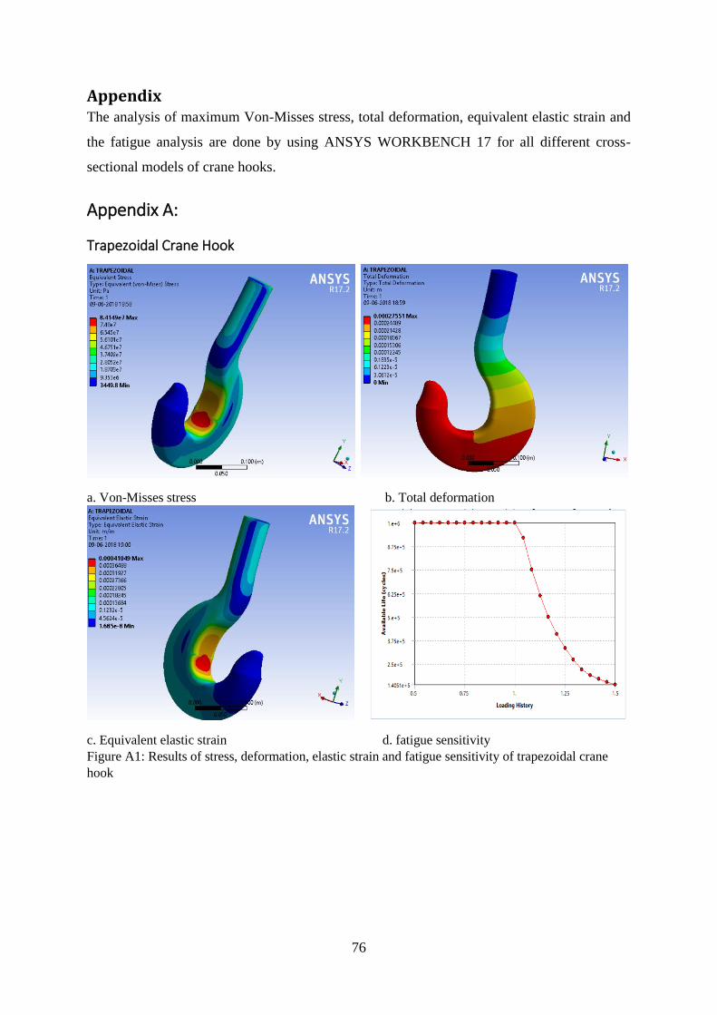
76
Appendix The analysis of maximum Von-Misses stress, total deformation, equivalent elastic strain and
the fatigue analysis are done by using ANSYS WORKBENCH 17 for all different cross-
sectional models of crane hooks.
Appendix A:
Trapezoidal Crane Hook
a. Von-Misses stress b. Total deformation
c. Equivalent elastic strain d. fatigue sensitivity
Figure A1: Results of stress, deformation, elastic strain and fatigue sensitivity of trapezoidal crane
hook
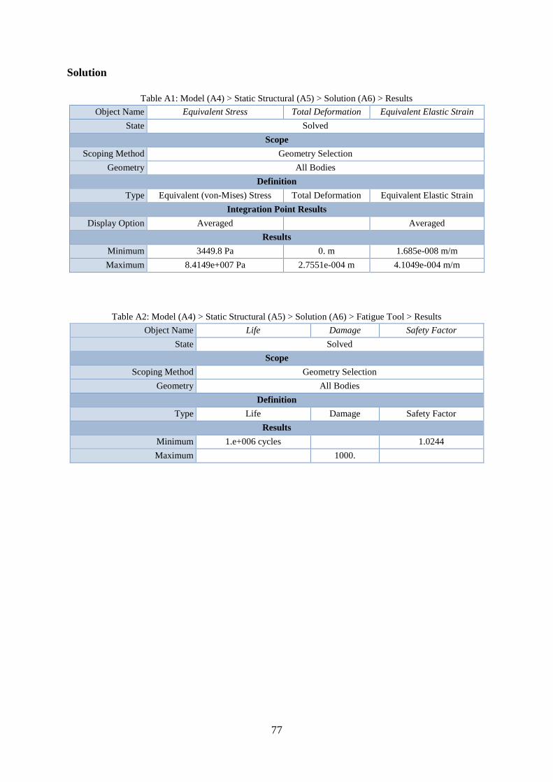
77
Solution
Table A1: Model (A4) > Static Structural (A5) > Solution (A6) > Results
Object Name Equivalent Stress Total Deformation Equivalent Elastic Strain
State Solved
Scope
Scoping Method Geometry Selection
Geometry All Bodies
Definition
Type Equivalent (von-Mises) Stress Total Deformation Equivalent Elastic Strain
Integration Point Results
Display Option Averaged Averaged
Results
Minimum 3449.8 Pa 0. m 1.685e-008 m/m
Maximum 8.4149e+007 Pa 2.7551e-004 m 4.1049e-004 m/m
Table A2: Model (A4) > Static Structural (A5) > Solution (A6) > Fatigue Tool > Results
Object Name Life Damage Safety Factor
State Solved
Scope
Scoping Method Geometry Selection
Geometry All Bodies
Definition
Type Life Damage Safety Factor
Results
Minimum 1.e+006 cycles 1.0244
Maximum 1000.
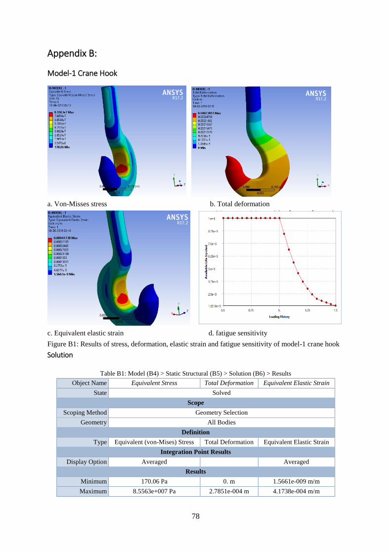
78
Appendix B:
Model-1 Crane Hook
a. Von-Misses stress b. Total deformation
c. Equivalent elastic strain d. fatigue sensitivity
Figure B1: Results of stress, deformation, elastic strain and fatigue sensitivity of model-1 crane hook
Solution
Table B1: Model (B4) > Static Structural (B5) > Solution (B6) > Results
Object Name Equivalent Stress Total Deformation Equivalent Elastic Strain
State Solved
Scope
Scoping Method Geometry Selection
Geometry All Bodies
Definition
Type Equivalent (von-Mises) Stress Total Deformation Equivalent Elastic Strain
Integration Point Results
Display Option Averaged Averaged
Results
Minimum 170.06 Pa 0. m 1.5661e-009 m/m
Maximum 8.5563e+007 Pa 2.7851e-004 m 4.1738e-004 m/m
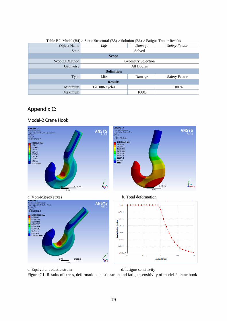
79
Table B2: Model (B4) > Static Structural (B5) > Solution (B6) > Fatigue Tool > Results
Object Name Life Damage Safety Factor
State Solved
Scope
Scoping Method Geometry Selection
Geometry All Bodies
Definition
Type Life Damage Safety Factor
Results
Minimum 1.e+006 cycles 1.0074
Maximum 1000.
Appendix C:
Model-2 Crane Hook
a. Von-Misses stress b. Total deformation
c. Equivalent elastic strain d. fatigue sensitivity
Figure C1: Results of stress, deformation, elastic strain and fatigue sensitivity of model-2 crane hook
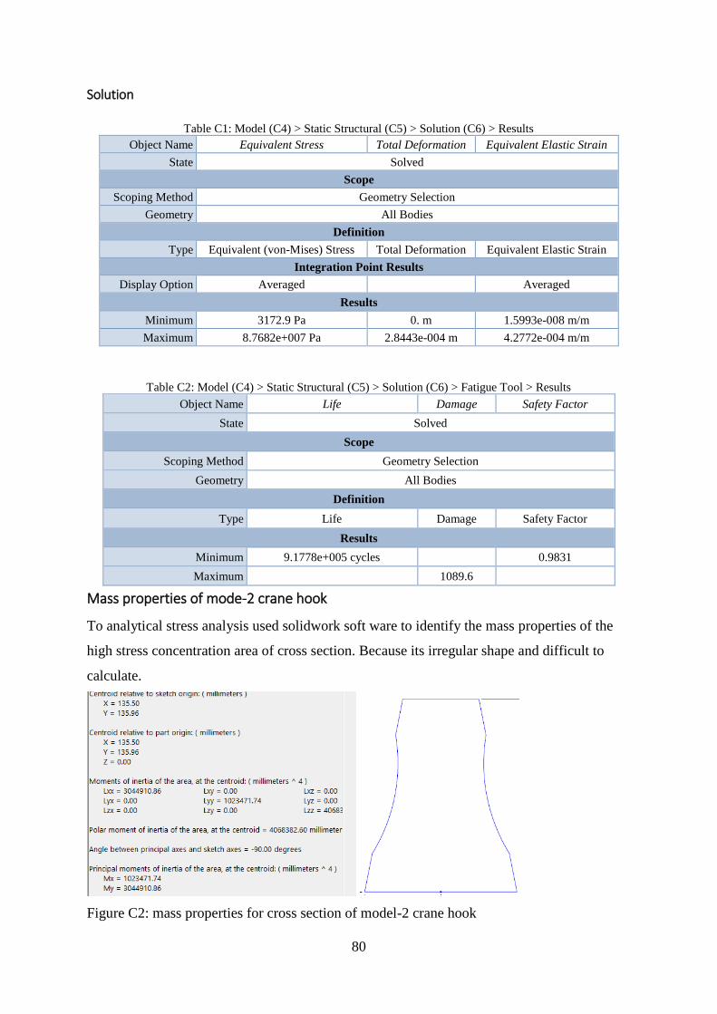
80
Solution
Table C1: Model (C4) > Static Structural (C5) > Solution (C6) > Results
Object Name Equivalent Stress Total Deformation Equivalent Elastic Strain
State Solved
Scope
Scoping Method Geometry Selection
Geometry All Bodies
Definition
Type Equivalent (von-Mises) Stress Total Deformation Equivalent Elastic Strain
Integration Point Results
Display Option Averaged Averaged
Results
Minimum 3172.9 Pa 0. m 1.5993e-008 m/m
Maximum 8.7682e+007 Pa 2.8443e-004 m 4.2772e-004 m/m
Table C2: Model (C4) > Static Structural (C5) > Solution (C6) > Fatigue Tool > Results
Object Name Life Damage Safety Factor
State Solved
Scope
Scoping Method Geometry Selection
Geometry All Bodies
Definition
Type Life Damage Safety Factor
Results
Minimum 9.1778e+005 cycles 0.9831
Maximum 1089.6
Mass properties of mode-2 crane hook
To analytical stress analysis used solidwork soft ware to identify the mass properties of the
high stress concentration area of cross section. Because its irregular shape and difficult to
calculate.
Figure C2: mass properties for cross section of model-2 crane hook
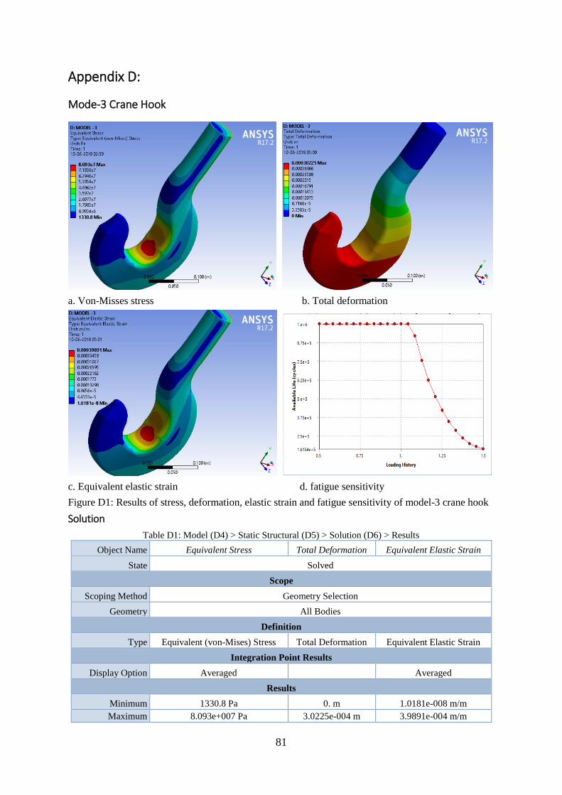
81
Appendix D:
Mode-3 Crane Hook
a. Von-Misses stress b. Total deformation
c. Equivalent elastic strain d. fatigue sensitivity
Figure D1: Results of stress, deformation, elastic strain and fatigue sensitivity of model-3 crane hook
Solution
Table D1: Model (D4) > Static Structural (D5) > Solution (D6) > Results
Object Name Equivalent Stress Total Deformation Equivalent Elastic Strain
State Solved
Scope
Scoping Method Geometry Selection
Geometry All Bodies
Definition
Type Equivalent (von-Mises) Stress Total Deformation Equivalent Elastic Strain
Integration Point Results
Display Option Averaged Averaged
Results
Minimum 1330.8 Pa 0. m 1.0181e-008 m/m
Maximum 8.093e+007 Pa 3.0225e-004 m 3.9891e-004 m/m
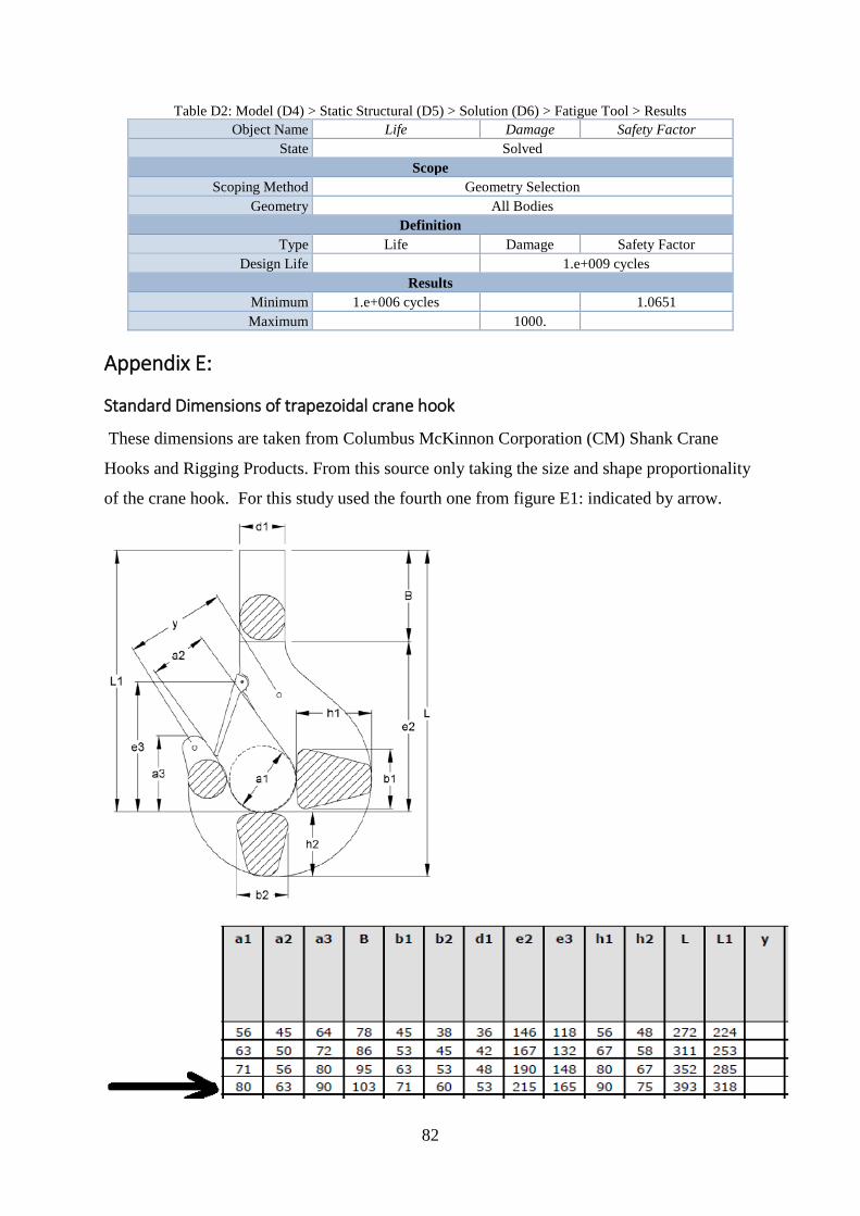
82
Table D2: Model (D4) > Static Structural (D5) > Solution (D6) > Fatigue Tool > Results
Object Name Life Damage Safety Factor
State Solved
Scope
Scoping Method Geometry Selection
Geometry All Bodies
Definition
Type Life Damage Safety Factor
Design Life 1.e+009 cycles
Results
Minimum 1.e+006 cycles 1.0651
Maximum 1000.
Appendix E:
Standard Dimensions of trapezoidal crane hook
These dimensions are taken from Columbus McKinnon Corporation (CM) Shank Crane
Hooks and Rigging Products. From this source only taking the size and shape proportionality
of the crane hook. For this study used the fourth one from figure E1: indicated by arrow.

83