Embed Size (px)
Citation preview
925
Optimal Placement of Piezoelectric Macro
Fiber Composite Patches on Composite
Plates for Vibration Suppression
1 INTRODUCTION
The increasing demand for light structures in important applications highlights the necessity for
using advanced methods in their design, as the structural optimization and optimal control. With
sensors and actuators integrated through control systems, these structures have the capacity of
sensing environment changes, diagnose localized problems, store and process measured data. They
are, then, able to take appropriate action to improve the efficiency of the system or to preserve
their structural integrity and safety [Cheng et al. (2008)]. Important applications, according to
Abstract
This work presents a new methodology for the parametric optimization of
piezoelectric actuators installed in laminated composite structures, with
the objective of controlling structural vibrations. Problem formulation is
the optimum location of a Macro Fiber Composite (MFC) actuator patch
by means the maximization of the controllability index. The control
strategy is based on a Linear Quadratic Regulator (LQR) approach. For
the structural analysis, the modeling of the interaction between the MFC
and the structure is made taking into account the active material as one
of the orthotropic laminate shell layers. The actuation itself is modeled as
an initial strain arising from the application of an electric potential which
deforms the rest of the structure. Thereby, modeling the electric field and
the electromechanical coupling within the actuator is avoided because
these effects are considered analytically. Numerical simulations show that
the structural model presents good agreement with numerical and
experimental results. Furthermore, the results show that optimizing the
location of the actuator in the structure helps the control algorithm to
reduce induced structural vibration.
Keywords
Parametric optimization, macro fiber composite, LQR optimal control,
laminated composite material.
Eduardo Padoin a
Jun Sergio Ono Fonseca b
Eduardo André Perondi c
Odair Menuzzi d
a GMAp – Applied Mechanics Group,
R. Sarmento Leite, 425, 90050-170
Porto Alegre, RS, Brazil
email: [email protected] b email: [email protected]
c email: [email protected]
d email: [email protected]
http://dx.doi.org/10.1590/1679-78251320
Received 29.04.2014
In revised form 13.11.2014
Accepted 15.12.2014
Available online 03.02.2015
926 E. Padoin et al. / Optimal Placement of Piezoelectric Macro Fiber Composite Patches on Composite Plates for Vibration Suppression
Latin American Journal of Solids and Structures 12 (2015) 925-947
Crawley (1994), are systems that can sense induced vibration and, thus, applying forces to
control the amplitudes. Smart structures are applied mainly in the aerospace industry, where
they can be found, for instance, in flexible robot manipulators [Zimcik and Yousefi (2003)].
The development of methods to design smart structures is a promising research field, fueled by
the existing demand for these structures and the great range of possible applications. In the
research area of structural design, the topologic and parametric optimization methods contribute
efficiently in the design of lighter structures, decreasing costs and the material utilized,
evidencing the sustainability aspects of these approaches [Haftka and Gürdal (1991), Bendsøe and
Sigmund (2003)].
Optimized structures usually present reduced mass and low internal damping. These features
induce the occurrence of structural vibrations, which may cause undesirable operational effects,
for instance in positioning accuracy. According to Preumont (2002), the use of an active control
system integrated by sensors and actuators is crucial in smart structures. This article presents the
application of a specific type of actuator, the MFC (Macro Fiber Composite) piezoelectric
transducer [Smart Material (2013)].
The use of piezoelectric ceramics (as the PZT) to generate mechanical force, or, as a sensor in
control systems, is relatively well known. When deformed, piezoelectric materials generate an
electric charge; conversely they undergo mechanical deformation when subjected to an electric
field. As an alternative to monolithic homogeneous ceramic inserts, some composite piezoelectric
devices such as the MFC were developed in the last decade. The MFC is a piezoelectric composite
actuator and consists in a plane array of PZT rods with wired comb shaped electrodes embedded
within polymeric layers. Considering that PZT is a brittle ceramic material, distributing it in thin
rods creates a flexible structure, allowing be bonded to curved structures.
This work uses a simplified model to represent the interaction between the MFC and the
structure. Most works models the electromechanical effect, where it is necessary to consider the
electric field generated between the electrodes, the piezoelectric constitutive model coupling
mechanical and electrical systems, resulting thus, in a complex multi-physics model [Latalski
(2011), Collet et al. (2010)]. Kapuria et al, 2010, present a review about the development of
efficient models and their numerical implementation for piezoelectric laminated plate, especially
to dynamics and control, free-edge stresses and micromechanical behavior. Besides, the future
challenges in smart composite structure technology are identified.
Differently from others works, we propose here the use of a simpler model to represent the
electromechanical interaction, being the structure modeled as a laminate shell and the MFC as
orthotropic material layers that present an initial strain. This strain is computed analytically as
resulting of the application of an instantaneous electric potential to the electrodes, and it is
converted into nodal forces during the finite element discretization. The numerical simulations
performed using the proposed approach show that the structural model presents good agreement
with numerical and experimental results.
A Linear Quadratic Regulator (LQR) controller is used to the structural vibration control.
The dynamic system is represented in state space using modal coordinates [Meirovitch (1990),
Preumont (2002) and Gawronski (2004)]. In the active control of structural vibrations using
piezoelectric material, the localization of sensors and actuators has significant influence in the
E. Padoin et al. / Optimal Placement of Piezoelectric Macro Fiber Composite Patches on Composite Plates for Vibration Suppression 927
Latin American Journal of Solids and Structures 12 (2015) 925-947
performance of the control system [Kumar e Narayanan, 2008]. Therefore, the present work
presents a new parametric optimization methodology that allows the optimal MFC placement by
means of the maximization of a controllability index. Sohn et al., 2011, present an optimization
technique for shells also using the MFC and a controllability index different from that used in the
present work, in which it was used the one proposed by Hac and Liu (1993). [Kang et al. (1996),
Quek et al. (2003)], present an optimal placement strategy of piezoelectric sensor/actuator pairs
using the maximum damping effect. The optimum location of the sensor/actuator is determined
as the point where the structural damping index is maximum.
Based on the aforementioned ideas, this work presents a parametric optimization of
piezoelectric actuators on laminated composite structures applied to reduce the structural
vibration induced by external forces. In comparison with other optimization forms, the proposed
parametric optimization helps to determine the optimal region to bond a commercially available
fixed dimension MFC patch in the structure.
2 MACRO FIBER COMPOSITE
The studies about piezoelectric ceramics for actuation and sensing are relatively advanced.
However, PZT presents significant restrictions that appear in some actual applications. The PZT
is a brittle material, requiring additional attention during the handling and assembly or bonding
procedures. Besides, its use in curved surfaces is difficult and may require additional treatment
[Kolovos et al. (2007)].
Composite piezoceramic actuators, which have been extensively studied in the last years, can
overcome these limitations. The MFC is one these solutions [Smart Material (2013)]. It was
developed by NASA for applications in which the structure flexibility prevails at expense of the
force capacity. It was developed to be used as sensor and actuator in vibration control and for
energy harvesting applications.
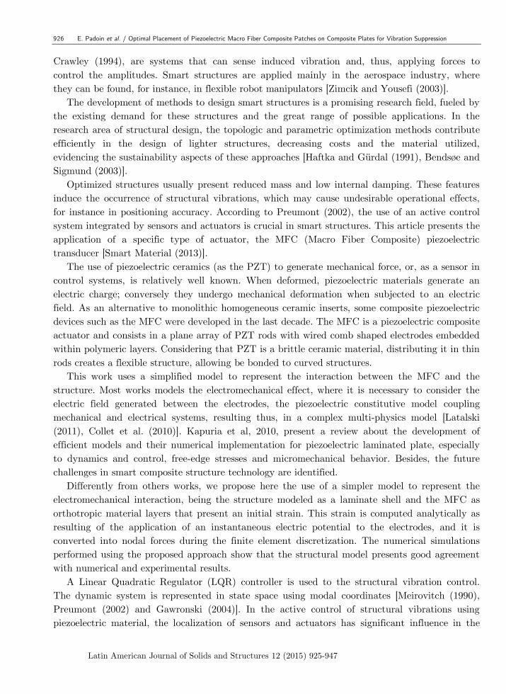
The MFC is constituted of rectangular piezoceramic rods sandwiched between layers of
adhesive material, electrodes and polyimide film, as shown in Figure 1. The electrodes are attached
to the film in an interdigitated pattern which transfers the applied voltage directly to and from
the ribbon shaped rods. This assembly enables in-plane poling, actuation and sensing in a sealed
and durable, ready to use device. As a thin, surface conformable sheet, it can be applied (normally
bonded) to various types of structures or embedded in a composite structure. If voltage is applied,
it can be used to bend or distort structures, generate or counteract vibrations. If no voltage is
applied, it can work as a strain gauge, sensing deformations, noise and vibrations.
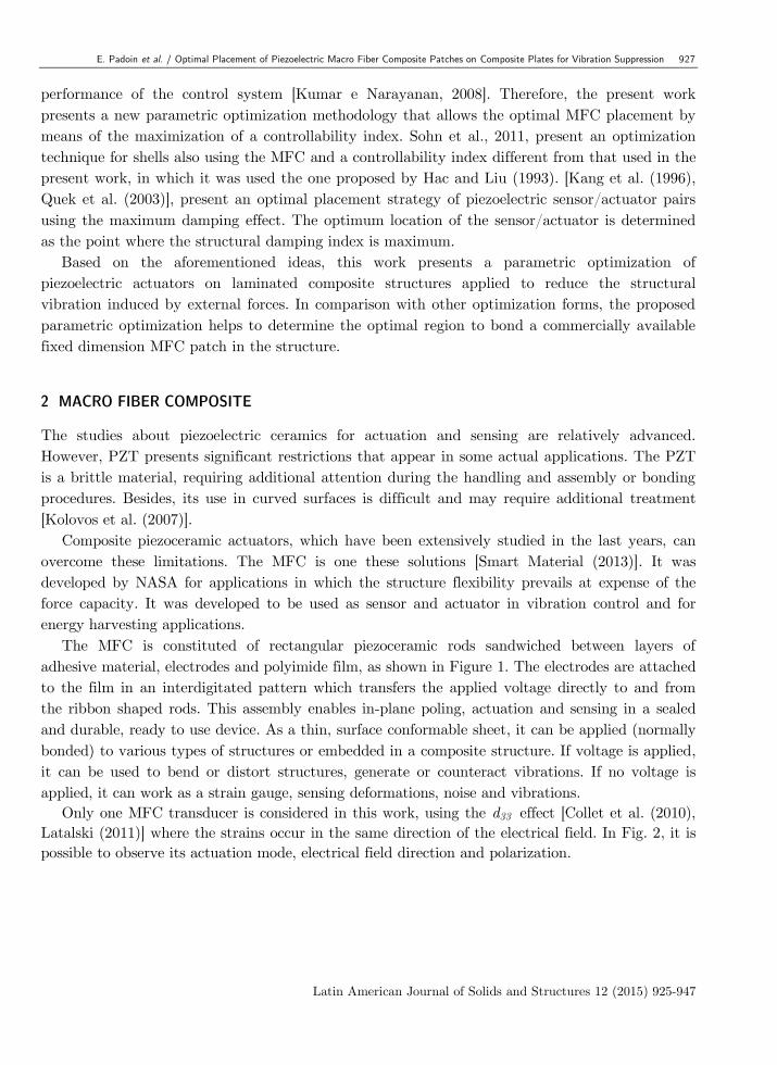
Only one MFC transducer is considered in this work, using the d33 effect [Collet et al. (2010),
Latalski (2011)] where the strains occur in the same direction of the electrical field. In Fig. 2, it is
possible to observe its actuation mode, electrical field direction and polarization.
928 E. Padoin et al. / Optimal Placement of Piezoelectric Macro Fiber Composite Patches on Composite Plates for Vibration Suppression
Latin American Journal of Solids and Structures 12 (2015) 925-947
Figure 1: MFC actuator construction, Kovalovs et al.(2007).
Figure 2: Electrical field and polarization for MFC effect, Schönecker et al. (2006).
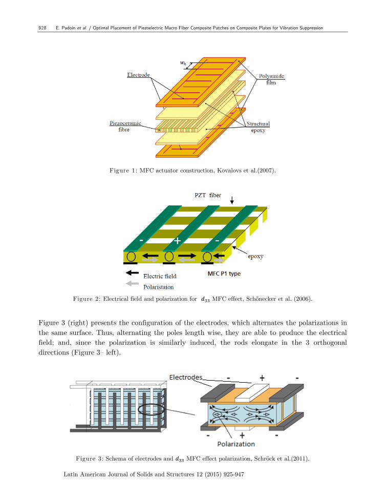
Figure 3 (right) presents the configuration of the electrodes, which alternates the polarizations in
the same surface. Thus, alternating the poles length wise, they are able to produce the electrical
field; and, since the polarization is similarly induced, the rods elongate in the 3 orthogonal
directions (Figure 3– left).
Figure 3: Schema of electrodes and MFC effect polarization, Schröck et al.(2011).
E. Padoin et al. / Optimal Placement of Piezoelectric Macro Fiber Composite Patches on Composite Plates for Vibration Suppression 929
Latin American Journal of Solids and Structures 12 (2015) 925-947
3 STRUCTURAL MODELING
The standard approximated solution of the solid mechanics equilibrium equations uses finite
element method (FEM) formulation. It uses the assumptions of the infinitesimal linear elasticity
and a lamination theory for the composite materials. Mass and stiffness matrices are derived for
an eight node serendipity quadrilateral shell element. The element is based on the degenerated
solid formulation by Ahmad et al. (1970), and it has five degrees-of-freedom (three displacements
and two slopes) per node. A good review of this element can be found in Zienkiewicz and Taylor
(2000). The laminated composite part is accounted using an explicit integration through the
thickness.
3.1 First-order Shear Deformation Laminated Theory
The First Order Deformation Laminated Theory (FSDT) is based on the Mindlin-Reissner plate
theory. It is assumed that a transverse normal segment does not necessarily remain perpendicular
to the midsurface after the deformation. The model allows transverse shear strains with linear
variation through the thickness [Reddy (2004)]. According Zhang and Yang (2009), the FSDT
offers a good compromise between computation efficient and accuracy of the global structural
behavior in comparison with the Classical Lamination Theory (CLT). In this theory, the
constitutive equation of laminated plate is described as:
(1)
where N and M are the distributed normal tractions and moments applied to the plate,
respectively. The terms are referred to the midplane (membrane) strains, while corresponds to
the curvatures terms.
The matrix is the extensional stiffness matrix that relates the extensional midplane strain
with the plate traction . It is written as:
(2)
where is the distance from laminate midplane to the bottom of the each -th layer, is the
transformed stiffness matrix and is the number of layers.
The stiffness matrix represents the coupling between bending and membrane tension forces,
which contains the contribution of the curvature in the traction. When the plate is symmetric,
. This matrix is given by:
(3)
930 E. Padoin et al. / Optimal Placement of Piezoelectric Macro Fiber Composite Patches on Composite Plates for Vibration Suppression
Latin American Journal of Solids and Structures 12 (2015) 925-947
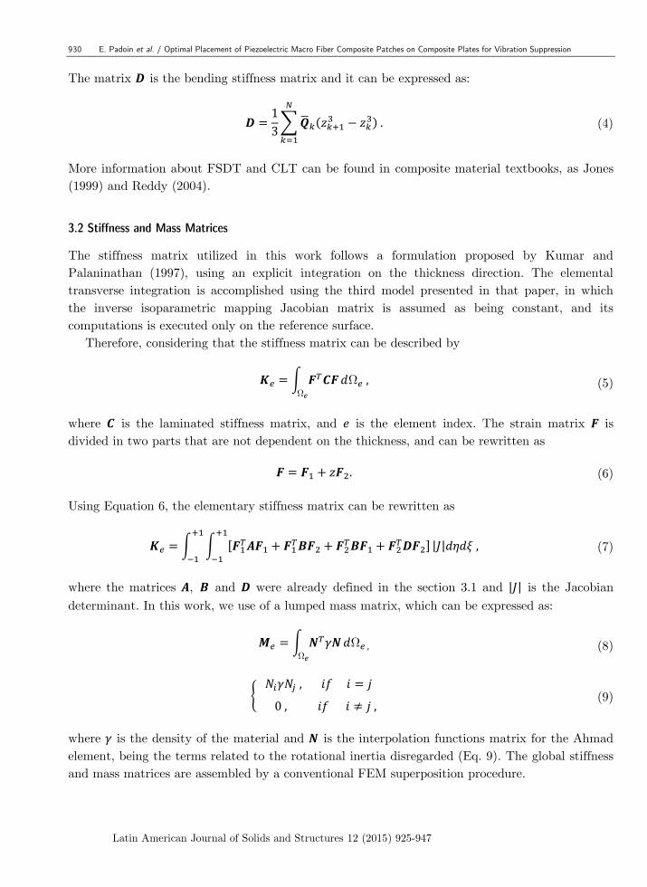
The matrix is the bending stiffness matrix and it can be expressed as:
(4)
More information about FSDT and CLT can be found in composite material textbooks, as Jones
(1999) and Reddy (2004).
3.2 Stiffness and Mass Matrices
The stiffness matrix utilized in this work follows a formulation proposed by Kumar and
Palaninathan (1997), using an explicit integration on the thickness direction. The elemental
transverse integration is accomplished using the third model presented in that paper, in which
the inverse isoparametric mapping Jacobian matrix is assumed as being constant, and its
computations is executed only on the reference surface.
Therefore, considering that the stiffness matrix can be described by
(5)
where is the laminated stiffness matrix, and is the element index. The strain matrix is
divided in two parts that are not dependent on the thickness, and can be rewritten as
(6)
Using Equation 6, the elementary stiffness matrix can be rewritten as
(7)
where the matrices , and were already defined in the section 3.1 and is the Jacobian
determinant. In this work, we use of a lumped mass matrix, which can be expressed as:
(8)
(9)
where is the density of the material and is the interpolation functions matrix for the Ahmad
element, being the terms related to the rotational inertia disregarded (Eq. 9). The global stiffness
and mass matrices are assembled by a conventional FEM superposition procedure.
E. Padoin et al. / Optimal Placement of Piezoelectric Macro Fiber Composite Patches on Composite Plates for Vibration Suppression 931
Latin American Journal of Solids and Structures 12 (2015) 925-947
3.3 Distributed Force Vector Due to the MFC
As already mentioned, a simplified model is proposed to represent the interaction between the
MFC actuator and the structure. This approach presents the advantage of needing less
implementation efforts than the alternative based on the modeling of the electric fields and
electromechanical effect. Assuming that the MFC is modeled as one of the orthotropic material
layers of the laminate shell, it is considered that an additional elemental force vector of
distributed loads is obtained from an initial strain existent in the MFC. This strain is
proportional to the electrical potential applied in the MFC. Therefore, it is not necessary to
model the electric field and the electromechanical coupling, because these effects are considered
analytically. Both the stiffness and the mass of the MFC are taken into account in the structural
model.
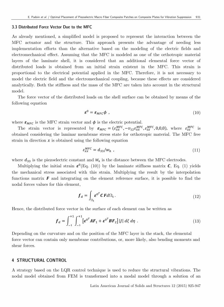
The force vector of the distributed loads on the shell surface can be obtained by means of the
following equation
(10)
where is the MFC strain vector and is the electric potential.
The strain vector is represented by
where
is
obtained considering the laminar membrane stress state for orthotropic material. The MFC free
strain in direction is obtained using the following equation
(11)
where is the piezoelectric constant and is the distance between the MFC electrodes.
Multiplying the initial strain (Eq. (10)) by the laminate stiffness matrix , Eq. (1) yields
the mechanical stress associated with this strain. Multiplying the result by the interpolation
functions matrix and integrating on the element reference surface, it is possible to find the
nodal forces values for this element,
(12)
Hence, the distributed force vector in the surface of each element can be written as
(13)
Depending on the curvature and on the position of the MFC layer in the stack, the elemental
force vector can contain only membrane contributions, or, more likely, also bending moments and
shear forces.
4 STRUCTURAL CONTROL
A strategy based on the LQR control technique is used to reduce the structural vibrations. The
nodal model obtained from FEM is transformed into a modal model through a solution of an
932 E. Padoin et al. / Optimal Placement of Piezoelectric Macro Fiber Composite Patches on Composite Plates for Vibration Suppression
Latin American Journal of Solids and Structures 12 (2015) 925-947
eigenproblem. Accordingly, it is possible to truncate the system for the most relevant vibration
modes, allowing that a real time controller could be implemented. Detailed reviews about LQR
control and modal model can be found in Preumont (2002) and Gawronski (2004).
4.1 Modal Model
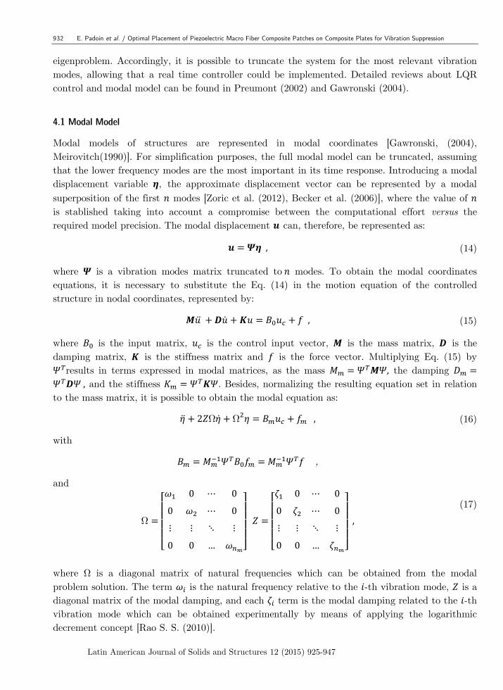
Modal models of structures are represented in modal coordinates [Gawronski, (2004),
Meirovitch(1990)]. For simplification purposes, the full modal model can be truncated, assuming
that the lower frequency modes are the most important in its time response. Introducing a modal
displacement variable , the approximate displacement vector can be represented by a modal
superposition of the first modes [Zoric et al. (2012), Becker et al. (2006)], where the value of
is stablished taking into account a compromise between the computational effort versus the
required model precision. The modal displacement can, therefore, be represented as:
(14)
where is a vibration modes matrix truncated to modes. To obtain the modal coordinates
equations, it is necessary to substitute the Eq. (14) in the motion equation of the controlled
structure in nodal coordinates, represented by:
(15)
where is the input matrix, is the control input vector, is the mass matrix, is the
damping matrix, is the stiffness matrix and is the force vector. Multiplying Eq. (15) by
results in terms expressed in modal matrices, as the mass the damping
and the stiffness . Besides, normalizing the resulting equation set in relation
to the mass matrix, it is possible to obtain the modal equation as:
(16)
with
,
and
(17)
where is a diagonal matrix of natural frequencies which can be obtained from the modal
problem solution. The term is the natural frequency relative to the -th vibration mode, is a
diagonal matrix of the modal damping, and each term is the modal damping related to the -th
vibration mode which can be obtained experimentally by means of applying the logarithmic
decrement concept [Rao S. S. (2010)].
E. Padoin et al. / Optimal Placement of Piezoelectric Macro Fiber Composite Patches on Composite Plates for Vibration Suppression 933
Latin American Journal of Solids and Structures 12 (2015) 925-947
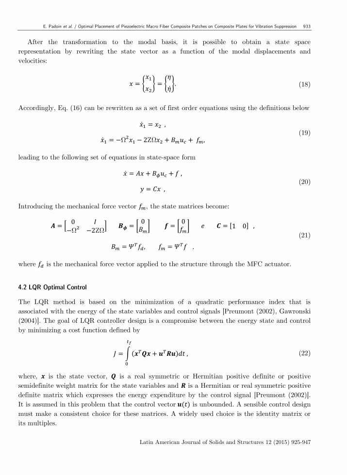
After the transformation to the modal basis, it is possible to obtain a state space
representation by rewriting the state vector as a function of the modal displacements and
velocities:
(18)
Accordingly, Eq. (16) can be rewritten as a set of first order equations using the definitions below
(19)
leading to the following set of equations in state-space form
(20)
Introducing the mechanical force vector , the state matrices become:
,
(21)
where is the mechanical force vector applied to the structure through the MFC actuator.
4.2 LQR Optimal Control
The LQR method is based on the minimization of a quadratic performance index that is
associated with the energy of the state variables and control signals [Preumont (2002), Gawronski
(2004)]. The goal of LQR controller design is a compromise between the energy state and control
by minimizing a cost function defined by
(22)
where, is the state vector, is a real symmetric or Hermitian positive definite or positive
semidefinite weight matrix for the state variables and is a Hermitian or real symmetric positive
definite matrix which expresses the energy expenditure by the control signal [Preumont (2002)].
It is assumed in this problem that the control vector is unbounded. A sensible control design
must make a consistent choice for these matrices. A widely used choice is the identity matrix or
its multiples.
934 E. Padoin et al. / Optimal Placement of Piezoelectric Macro Fiber Composite Patches on Composite Plates for Vibration Suppression
Latin American Journal of Solids and Structures 12 (2015) 925-947
In the LQR approach [Preumont (2002)], an optimal control law can be expressed through Eq.
(23):
(23)
If the matrix of elements is determined to minimize the performance index (Eq. 22), then
is suitable for any initial state
In the standard LQR approach, the optimal gain matrix is expressed by , where
is the solution of the Riccati equation:
(24)
Considering a state feedback control, the closed-loop state equation is, hence, given by:
(25)
As a hypothesis, it is assumed that all states are completely measurable or observable and that
they are related to the outputs.
For the optimization problem solution, it is necessary to define the system property to be
maximized. In the present work, as in Zoric et al. (2012), the optimization task is defined as
finding the position for the piezoelectric actuators where the control action spends less energy in
the effort dispended to attenuating structural vibrations. Therefore, a performance index
associated to the system controllability is adopted. As, for example, in Becker et al. (2006), the
measure of the system controllability is performed through the use of the trace of the so-called
Gramian controllability matrix , which is defined by the following Lyapunov equation
[Preumont (2002)]:
(26)
where and are the matrices defined in the Eq. (21) and is the Gramian controllability
matrix.
5 RESULTS
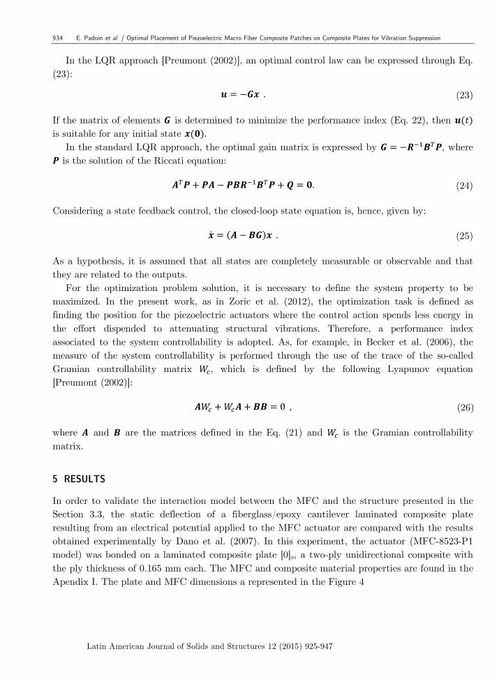
In order to validate the interaction model between the MFC and the structure presented in the
Section 3.3, the static deflection of a fiberglass/epoxy cantilever laminated composite plate
resulting from an electrical potential applied to the MFC actuator are compared with the results
obtained experimentally by Dano et al. (2007). In this experiment, the actuator (MFC-8523-P1
model) was bonded on a laminated composite plate [0]s, a two-ply unidirectional composite with
the ply thickness of 0.165 mm each. The MFC and composite material properties are found in the
Apendix I. The plate and MFC dimensions a represented in the Figure 4
E. Padoin et al. / Optimal Placement of Piezoelectric Macro Fiber Composite Patches on Composite Plates for Vibration Suppression 935
Latin American Journal of Solids and Structures 12 (2015) 925-947
Figure 4: Cantilever laminated composite plate with a MFC actuator bonded to the structure.
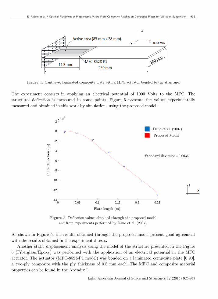
The experiment consists in applying an electrical potential of 1000 Volts to the MFC. The
structural deflection is measured in some points. Figure 5 presents the values experimentally
measured and obtained in this work by simulations using the proposed model.
Figure 5: Deflection values obtained through the proposed model
and from experiments performed by Dano et al. (2007).
As shown in Figure 5, the results obtained through the proposed model present good agreement
with the results obtained in the experimental tests.
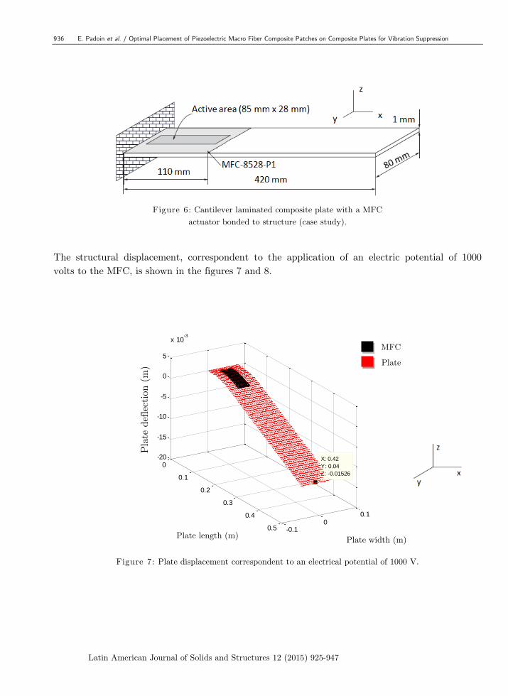
Another static displacement analysis using the model of the structure presented in the Figure
6 (Fiberglass/Epoxy) was performed with the application of an electrical potential in the MFC
actuator. The actuator (MFC-8523-P1 model) was bonded on a laminated composite plate [0,90],
a two-ply composite with the ply thickness of 0.5 mm each. The MFC and composite material
properties can be found in the Apendix I.
0 0.05 0.1 0.15 0.2 0.25-14
-12
-10
-8
-6
-4
-2
0
2x 10
-3
Comprimento da Placa (m)
Deflexão d
a P
laca (
m)
Dano et al. (2007)
Proposed Model
Plate length (m)
Pla
te d
efle
ctio
n (
m)
Standard deviation=0.0036
936 E. Padoin et al. / Optimal Placement of Piezoelectric Macro Fiber Composite Patches on Composite Plates for Vibration Suppression
Latin American Journal of Solids and Structures 12 (2015) 925-947
Figure 6: Cantilever laminated composite plate with a MFC
actuator bonded to structure (case study).
The structural displacement, correspondent to the application of an electric potential of 1000
volts to the MFC, is shown in the figures 7 and 8.
Figure 7: Plate displacement correspondent to an electrical potential of 1000 V.
0
0.1
0.2
0.3
0.4
0.5 -0.10
0.1
-20
-15
-10
-5
0
5
x 10-3
Largura da Placa (m)
X: 0.42
Y: 0.04
Z: -0.01526
Comprimento da Placa (m)
Deflexão d
a P
laca (
m)
MFC
Plate
Plate length (m)
Pla
te d
efle
ctio
n (
m)
Plate width (m)
E. Padoin et al. / Optimal Placement of Piezoelectric Macro Fiber Composite Patches on Composite Plates for Vibration Suppression 937
Latin American Journal of Solids and Structures 12 (2015) 925-947
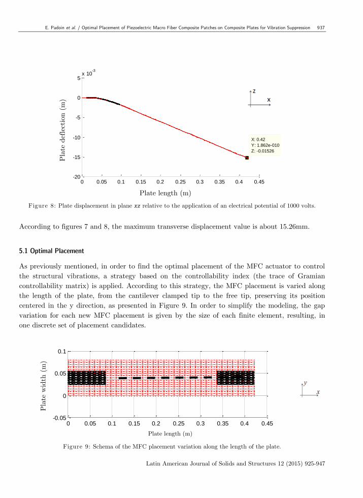
Figure 8: Plate displacement in plane relative to the application of an electrical potential of 1000 volts.
According to figures 7 and 8, the maximum transverse displacement value is about 15.26mm.
5.1 Optimal Placement
As previously mentioned, in order to find the optimal placement of the MFC actuator to control
the structural vibrations, a strategy based on the controllability index (the trace of Gramian
controllability matrix) is applied. According to this strategy, the MFC placement is varied along
the length of the plate, from the cantilever clamped tip to the free tip, preserving its position
centered in the y direction, as presented in Figure 9. In order to simplify the modeling, the gap
variation for each new MFC placement is given by the size of each finite element, resulting, in
one discrete set of placement candidates.
Figure 9: Schema of the MFC placement variation along the length of the plate.
0 0.05 0.1 0.15 0.2 0.25 0.3 0.35 0.4 0.45-20
-15
-10
-5
0
5x 10
-3
X: 0.42
Y: 1.862e-010
Z: -0.01526
Comprimento da Placa (m)
Deflexão d
a P
laca (
m)
0 0.05 0.1 0.15 0.2 0.25 0.3 0.35 0.4 0.45-0.05
0
0.05
0.1
Comprimento da Placa (m)
Larg
ura
da P
laca (
m)
Plate length (m)
Pla
te d
efle
ctio
n (
m)
Pla
te w
idth
(m
)
Plate length (m)
938 E. Padoin et al. / Optimal Placement of Piezoelectric Macro Fiber Composite Patches on Composite Plates for Vibration Suppression
Latin American Journal of Solids and Structures 12 (2015) 925-947
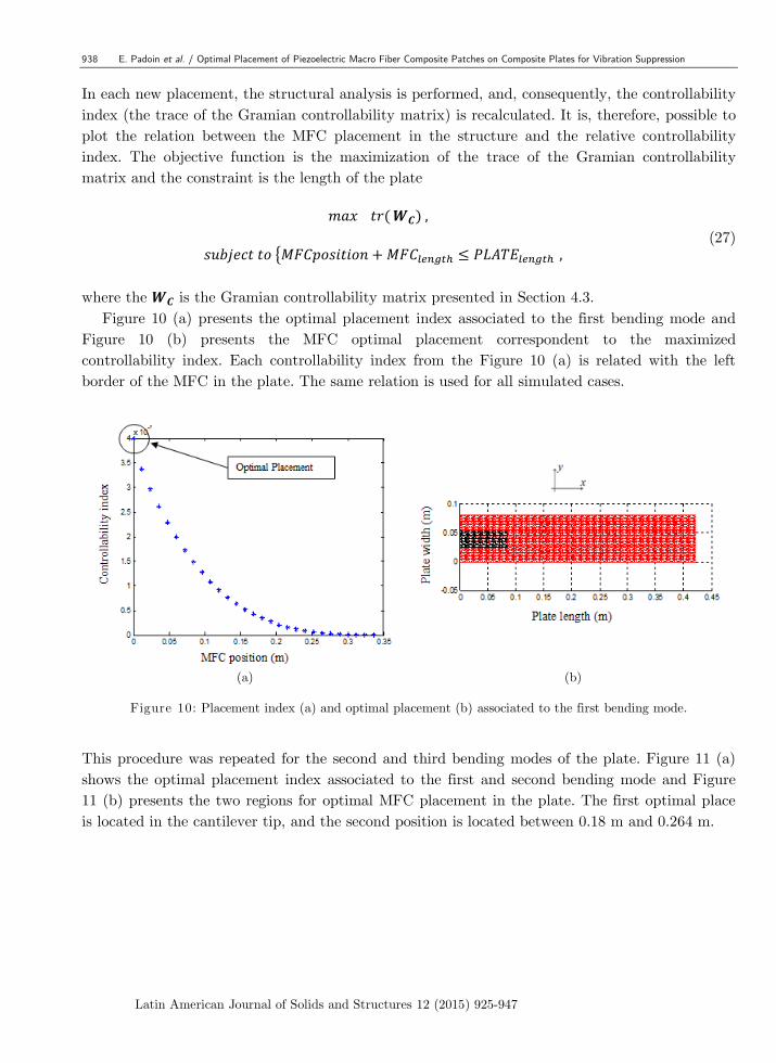
In each new placement, the structural analysis is performed, and, consequently, the controllability
index (the trace of the Gramian controllability matrix) is recalculated. It is, therefore, possible to
plot the relation between the MFC placement in the structure and the relative controllability
index. The objective function is the maximization of the trace of the Gramian controllability
matrix and the constraint is the length of the plate
(27)
where the is the Gramian controllability matrix presented in Section 4.3.
Figure 10 (a) presents the optimal placement index associated to the first bending mode and
Figure 10 (b) presents the MFC optimal placement correspondent to the maximized
controllability index. Each controllability index from the Figure 10 (a) is related with the left
border of the MFC in the plate. The same relation is used for all simulated cases.
(a) (b)
Figure 10: Placement index (a) and optimal placement (b) associated to the first bending mode.
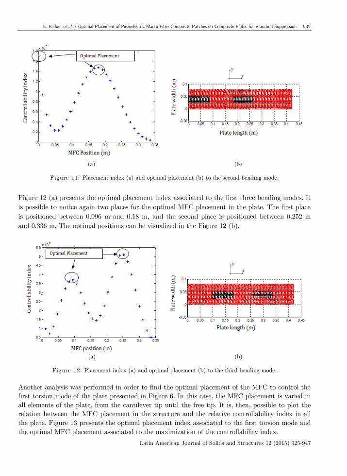
This procedure was repeated for the second and third bending modes of the plate. Figure 11 (a)
shows the optimal placement index associated to the first and second bending mode and Figure
11 (b) presents the two regions for optimal MFC placement in the plate. The first optimal place
is located in the cantilever tip, and the second position is located between 0.18 m and 0.264 m.
E. Padoin et al. / Optimal Placement of Piezoelectric Macro Fiber Composite Patches on Composite Plates for Vibration Suppression 939
Latin American Journal of Solids and Structures 12 (2015) 925-947
(a) (b)
Figure 11: Placement index (a) and optimal placement (b) to the second bending mode.
Figure 12 (a) presents the optimal placement index associated to the first three bending modes. It
is possible to notice again two places for the optimal MFC placement in the plate. The first place
is positioned between 0.096 m and 0.18 m, and the second place is positioned between 0.252 m
and 0.336 m. The optimal positions can be visualized in the Figure 12 (b).
(a) (b)
Figure 12: Placement index (a) and optimal placement (b) to the third bending mode.
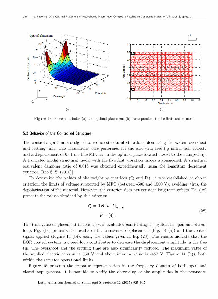
Another analysis was performed in order to find the optimal placement of the MFC to control the
first torsion mode of the plate presented in Figure 6. In this case, the MFC placement is varied in
all elements of the plate, from the cantilever tip until the free tip. It is, then, possible to plot the
relation between the MFC placement in the structure and the relative controllability index in all
the plate. Figure 13 presents the optimal placement index associated to the first torsion mode and
the optimal MFC placement associated to the maximization of the controllability index.
940 E. Padoin et al. / Optimal Placement of Piezoelectric Macro Fiber Composite Patches on Composite Plates for Vibration Suppression
Latin American Journal of Solids and Structures 12 (2015) 925-947
(a) (b)
Figure 13: Placement index (a) and optimal placement (b) correspondent to the first torsion mode.
5.2 Behavior of the Controlled Structure
The control algorithm is designed to reduce structural vibrations, decreasing the system overshoot
and settling time. The simulations were performed for the case with free tip initial null velocity
and a displacement of 0.01 m. The MFC is on the optimal place located closed to the clamped tip.
A truncated modal structural model with the five first vibration modes is considered. A structural
equivalent damping ratio of 0.018 was obtained experimentally using the logarithm decrement
equation [Rao S. S. (2010)].
To determine the values of the weighting matrices (Q and R), it was established as choice
criterion, the limits of voltage supported by MFC (between -500 and 1500 V), avoiding, thus, the
depolarization of the material. However, the criterion does not consider long term effects. Eq. (28)
presents the values obtained by this criterion.
(28)
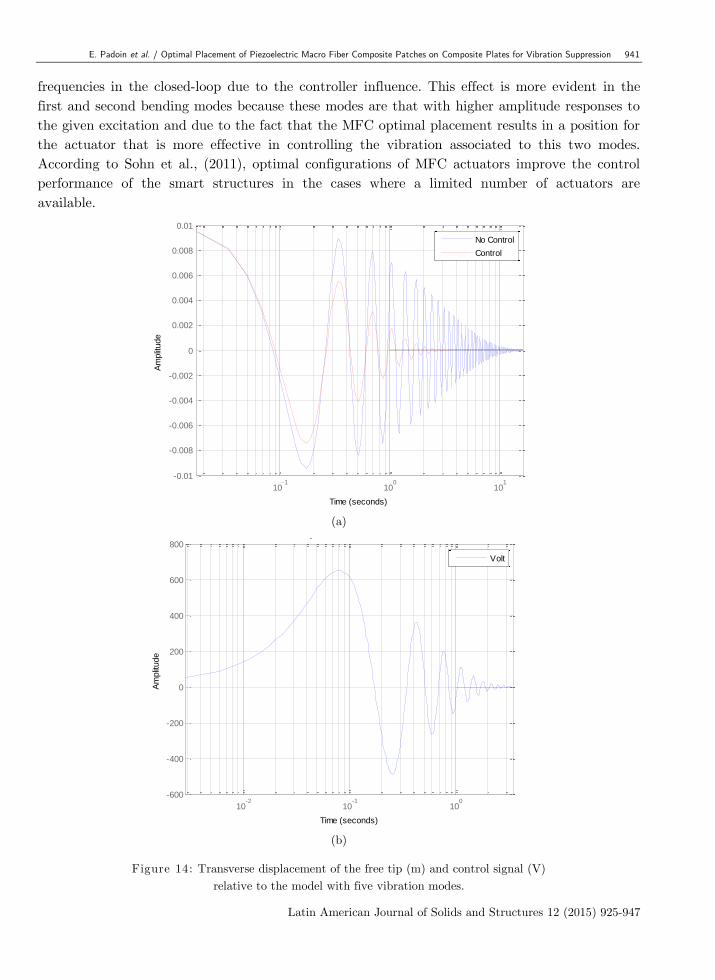
The transverse displacement in free tip was evaluated considering the system in open and closed-
loop. Fig. (14) presents the results of the transverse displacement (Fig. 14 (a)) and the control
signal applied (Figure 14 (b)), using the values given in Eq. (28). The results indicate that the
LQR control system in closed-loop contributes to decrease the displacement amplitude in the free
tip. The overshoot and the settling time are also significantly reduced. The maximum value of
the applied electric tension is 650 V and the minimum value is -487 V (Figure 14 (b)), both
within the actuator operational limits.
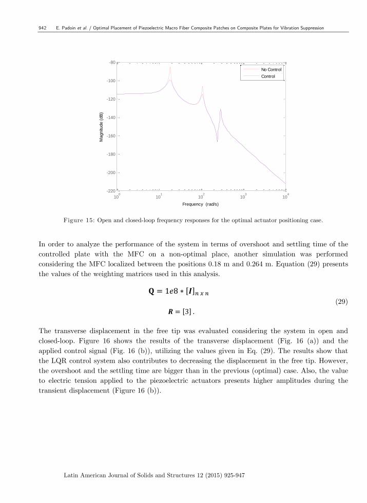
Figure 15 presents the response representation in the frequency domain of both open and
closed-loop systems. It is possible to verify the decreasing of the amplitudes in the resonance
E. Padoin et al. / Optimal Placement of Piezoelectric Macro Fiber Composite Patches on Composite Plates for Vibration Suppression 941
Latin American Journal of Solids and Structures 12 (2015) 925-947
frequencies in the closed-loop due to the controller influence. This effect is more evident in the
first and second bending modes because these modes are that with higher amplitude responses to
the given excitation and due to the fact that the MFC optimal placement results in a position for
the actuator that is more effective in controlling the vibration associated to this two modes.
According to Sohn et al., (2011), optimal configurations of MFC actuators improve the control
performance of the smart structures in the cases where a limited number of actuators are
available.
(a)
(b)
Figure 14: Transverse displacement of the free tip (m) and control signal (V)
relative to the model with five vibration modes.
10-1
100
101
-0.01
-0.008
-0.006
-0.004
-0.002
0
0.002
0.004
0.006
0.008
0.01
Response to Initial Conditions
Time (seconds)
Am
plit
ude
No Control
Control
10-2
10-1
100
-600
-400
-200
0
200
400
600
800
Response to Initial Conditions
Time (seconds)
Am
plit
ude
Volt
942 E. Padoin et al. / Optimal Placement of Piezoelectric Macro Fiber Composite Patches on Composite Plates for Vibration Suppression
Latin American Journal of Solids and Structures 12 (2015) 925-947
Figure 15: Open and closed-loop frequency responses for the optimal actuator positioning case.
In order to analyze the performance of the system in terms of overshoot and settling time of the
controlled plate with the MFC on a non-optimal place, another simulation was performed
considering the MFC localized between the positions 0.18 m and 0.264 m. Equation (29) presents
the values of the weighting matrices used in this analysis.
(29)
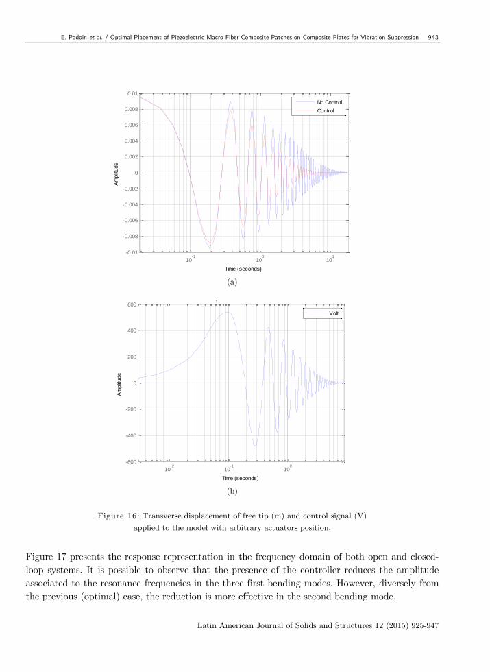
The transverse displacement in the free tip was evaluated considering the system in open and
closed-loop. Figure 16 shows the results of the transverse displacement (Fig. 16 (a)) and the
applied control signal (Fig. 16 (b)), utilizing the values given in Eq. (29). The results show that
the LQR control system also contributes to decreasing the displacement in the free tip. However,
the overshoot and the settling time are bigger than in the previous (optimal) case. Also, the value
to electric tension applied to the piezoelectric actuators presents higher amplitudes during the
transient displacement (Figure 16 (b)).
100
101
102
103
104
-220
-200
-180
-160
-140
-120
-100
-80
Magnitu
de (
dB
)
Bode Diagram
Frequency (rad/s)
No Control
Control
E. Padoin et al. / Optimal Placement of Piezoelectric Macro Fiber Composite Patches on Composite Plates for Vibration Suppression 943
Latin American Journal of Solids and Structures 12 (2015) 925-947
(a)
(b)
Figure 16: Transverse displacement of free tip (m) and control signal (V)
applied to the model with arbitrary actuators position.
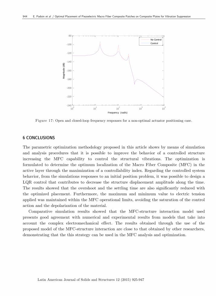
Figure 17 presents the response representation in the frequency domain of both open and closed-
loop systems. It is possible to observe that the presence of the controller reduces the amplitude
associated to the resonance frequencies in the three first bending modes. However, diversely from
the previous (optimal) case, the reduction is more effective in the second bending mode.
10-1
100
101
-0.01
-0.008
-0.006
-0.004
-0.002
0
0.002
0.004
0.006
0.008
0.01
Response to Initial Conditions
Time (seconds)
Am
plit
ude
No Control
Control
10-2
10-1
100
-600
-400
-200
0
200
400
600
Response to Initial Conditions
Time (seconds)
Am
plit
ude
Volt
944 E. Padoin et al. / Optimal Placement of Piezoelectric Macro Fiber Composite Patches on Composite Plates for Vibration Suppression
Latin American Journal of Solids and Structures 12 (2015) 925-947
Figure 17: Open and closed-loop frequency responses for a non-optimal actuator positioning case.
6 CONCLUSIONS
The parametric optimization methodology proposed in this article shows by means of simulation
and analysis procedures that it is possible to improve the behavior of a controlled structure
increasing the MFC capability to control the structural vibrations. The optimization is
formulated to determine the optimum localization of the Macro Fiber Composite (MFC) in the
active layer through the maximization of a controllability index. Regarding the controlled system
behavior, from the simulations responses to an initial position problem, it was possible to design a
LQR control that contributes to decrease the structure displacement amplitude along the time.
The results showed that the overshoot and the settling time are also significantly reduced with
the optimized placement. Furthermore, the maximum and minimum value to electric tension
applied was maintained within the MFC operational limits, avoiding the saturation of the control
action and the depolarization of the material.
Comparative simulation results showed that the MFC-structure interaction model used
presents good agreement with numerical and experimental results from models that take into
account the complex electromechanical effect. The results obtained through the use of the
proposed model of the MFC-structure interaction are close to that obtained by other researchers,
demonstrating that the this strategy can be used in the MFC analysis and optimization.
100
101
102
103
104
-240
-220
-200
-180
-160
-140
-120
-100
-80
Magnitu
de (
dB
)
Bode Diagram
Frequency (rad/s)
No Control
Control
E. Padoin et al. / Optimal Placement of Piezoelectric Macro Fiber Composite Patches on Composite Plates for Vibration Suppression 945
Latin American Journal of Solids and Structures 12 (2015) 925-947
References
Ahmad, S.; Irons, B. M. and Zienckievicz, O. C. (1970). Analysis of Think and Thin Shell Structure by Curved
Finite Elements, International Journal for Numericas Methods in Engineering, vol, 2, p. 419-451.
Becker, J.; Fein, O.; Maess, M. and Gaul, L.(2006). Finite element-based analysis of shunted piezoelectric
structures for vibration damping, Computers and Structures, Vol. 84, p. 2340–2350.
Bendsøe, M. e Sigmund, O. (2003). Topology Optimization - Theory, Methods and Applications. Springer, Berlin.
Cheng, Y. F.; Jiang, H. and Lou K. (2008). Smart Structures: Innovative Systems for Seismic Response Control.
Collet, M.;Ruzzene, M.; Cunefare, K. and Xu, B. (2010). Modeling and Characterization of Macro-Fiber
Composite Transducers for Lamb Wave Excitation, Health Monitoring of Structural and Biological Systems.
Crawley, E.F. (1994). Intelligent Structures for aerospace: A technology overview and assessment, AIAA Journal,
Vol. 32. P. 1689-1699.
Dano, M. L.; Gakwaya, M. and Julliè Re, B. (2007). Compensation of Thermally Induced Distortion in Composite
Structures using Macro-fiber Composites, Journal of Intelligent Material Systems and Structures.
Gawronski, W. (2004). Advanced Structural Dynamics and Active Control of Structures. Springer, New York.
Hac A, Lui L. (1993). Sensor and actuator location in motion control of flexible structures. Journal of Sound and
Vibration.V. 167(2), pp. 239–261.
Haftka, R. and Gürdal, Z. (1991). Elements of Structural Optimization. Kluver Academic Publishers, 3rd edition.
Jones, R. M. (1999). Mechanics of Composite Materials. Scripta Book Company, Washington, 2nd edtion.
Kang K. Y.; Park H. C.; Hwang W.; Han K. S. (1996). Optimum Placement of Piezoelectric Sensor/Actuator for
Vibration Control of Laminated Beams. AIAA Journal, Vol. 34.
Kapuria S.; Kumari P.; Nath J. K. (2010). Efficient modeling of smart piezoelectric composite laminates: a review,
Acta Mechanical ,vol.
214, Issue 1-2, pp 31-48.
Kovalovs A.; Barkanov E.; Gluhihs S. (2007). Active control of structures using macro-fiber composite (MFC),
Journal of Physics: Conference Series 93.
Kumar, R. and Narayanan, S. (2008). Active vibration control of beams with optimal placement of piezoelectric
sensor/actuator pairs, Smart Materials and Structures, vol. 17, pp. 01–15.
Kumar, W. P. P. and Palaninathan, R. (1997). Finite Element Analysis of Laminated Shells with Exact Through-
Thickness Integration, Computers and Structures, Vol, 63(1), p.173-184.
Latalski, J. (2011). Modelling of macro fiber composite piezoelectric active elements in ABA QUS system,
Maintenance And Reliability NR 4.
Meirovitch, L. (1990). Dynamics and Control of Structures. John Wiley & Sons, New York.
Preumont, A. (2002).Vibration Control of Active Structures, An Introduction. Kluwer.
Quek S. T.; Wang S. Y.; Ang K. K. (2003). Vibration Control of Composite Plates via optimal Placement of
Piezoelectric Patches. Journal of Intelligent Material systems and Structures, Vol. 14.
Rao. S. S. (2010).Mechanical Vibrations. Prentice Hall, 3 thedition.
Reddy, J. N. (2004). Mechanics of Composite Plates and Shells – Theory and Analysis. John Willey & Sons, Inc.
Schönecker, A. J.; Daue, T.; Brückner, B.; Freytag, C.; Hähne L and Rödig T. (2006). Overview on Macro Fiber
Composite Applications, Smart Structures and Materials: Active Materials: Behavior and Mechanics.
Schröck, J.; Meurer, T. and Kugi, A. (2011).Control of a flexible beam actuated by macro-fiber composite
patches: I. Modeling and feedforward trajectory control, Smart Materials And Structures, Vol. 20.
946 E. Padoin et al. / Optimal Placement of Piezoelectric Macro Fiber Composite Patches on Composite Plates for Vibration Suppression
Latin American Journal of Solids and Structures 12 (2015) 925-947
Smart Material. (2013). http://www.smart-material.com/MFC-product-main.html. The research was done on
March 11.
Sohn, J. W.; Choi, S. B. and Kim, H. S. (2011). Vibration control of smart hull structure with optimally placed
piezoelectric composite actuators, International Journal of Mechanical Sciences, Vol. 53, p. 647–659.
Zhang, Y. X. and Yang, Z. h. (2009). Recent Developments in Finite Element Analysis For Laminated Composite
Plates, Composite Structures, Vol. 88, p. 147-157.
Zienkiewicz, O. and Taylor, R. L. (2000). The Finite Element Method – Solid Mechanics. Vol. 2, Elsevier
Academic Press, 5th edition.
Zimcik, D. G.; Yousefi-Koma A. (2003). Applications of Smart Structures to Aircraft for Performance
Enhancement, Canadian Aeronautics and Space Journal, Vol. 49, p. 163-172.
Zoric N. D.; Simonovic, A. M.; Mitrovic, Z. S. and Stupar, S. N. (2012).Optimal vibration control of smart
composite beams with optimal size and location of piezoelectric sensing and actuation, Journal of Intelligent
Material Systems and Structures, Vol. 24(4), p. 499–526.
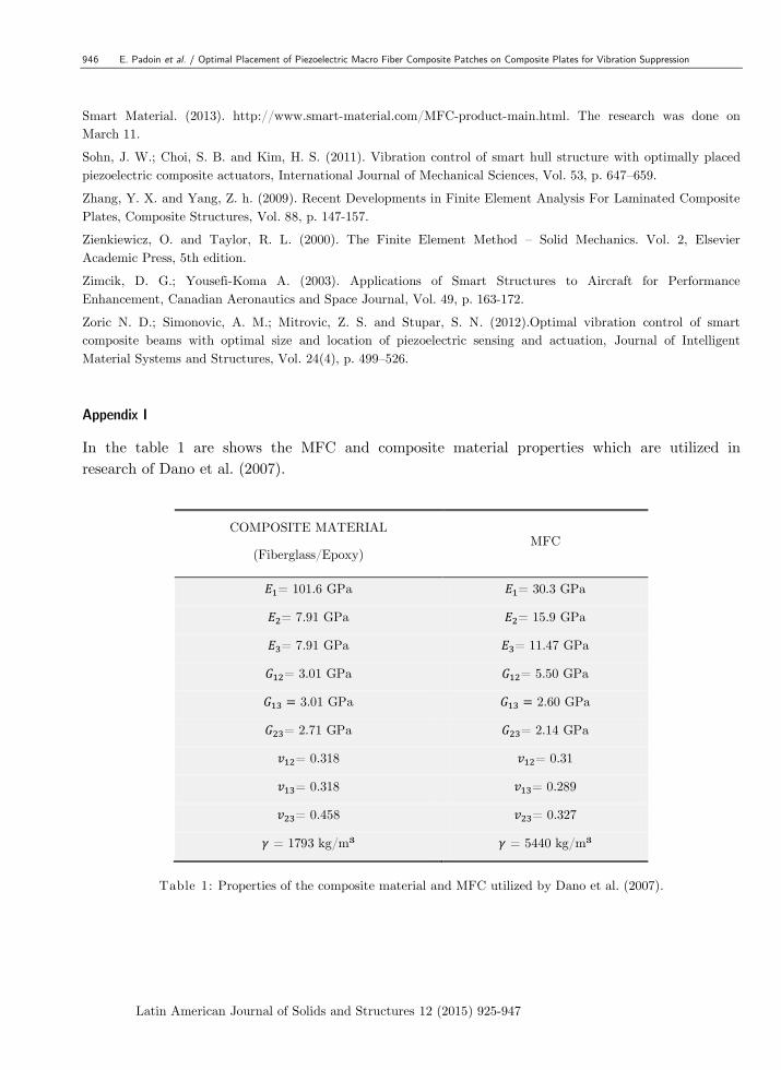
Appendix I
In the table 1 are shows the MFC and composite material properties which are utilized in
research of Dano et al. (2007).
COMPOSITE MATERIAL
(Fiberglass/Epoxy) MFC
= 101.6 GPa = 30.3 GPa
= 7.91 GPa = 15.9 GPa
= 7.91 GPa = 11.47 GPa
= 3.01 GPa = 5.50 GPa
3.01 GPa 2.60 GPa
= 2.71 GPa = 2.14 GPa
= 0.318 = 0.31
= 0.318 = 0.289
= 0.458 = 0.327
= 1793 kg/m³ = 5440 kg/m³
Table 1: Properties of the composite material and MFC utilized by Dano et al. (2007).

E. Padoin et al. / Optimal Placement of Piezoelectric Macro Fiber Composite Patches on Composite Plates for Vibration Suppression 947
Latin American Journal of Solids and Structures 12 (2015) 925-947
Where are the elastic modulus of material in the directions 1, 2 and 3, respectively,
are the Poisson coefficients and are the shear modulus in the planes 1-2,
2-3 and 3-1, respectively.
Table 2 shows the properties of a layer of the plate which was used to validate the numeric
model, and the MFC properties, where 1 is the fiber direction;
COMPOSITE MATERIAL
(Fiberglass/Epoxy) MFC
= 29.09GPa = 30.336 GPa
= 8.841 GPa = = 15.857 GPa
= 2.726 GPa = = 5.515 GPa
= 1.205 GPa = 2.6GPa
= = 0.1434 = = 0.31
= 0.2933 = 0.327
= 1793 kg/m³ = 5440 kg/m³
Table 2: Properties of the composite material and MFC.