Embed Size (px)
Citation preview
ERJ Engineering Research Journal
Faculty of Engineering
Minoufiya University
Engineering Research Journal, Vol. 37, No. 2, April 2014, PP: 143-155. © Faculty of Engineering, Minoufiya University, Egypt
143
Optimal PI Gains Scheduler for Three Phase Induction Motor Drive Using PSO
Hussein M. Wally Haitham Z. Azazi Fahmy M. El-Khouly Assistant Researcher, epartment of Electrical Engineering, Department of Electrical Engineering,
Mechanical & Electrical Research Center, Faculty of Engineering, Faculty of Engineering,
National Water Research Center, Egypt. Menoufiya University, Egypt. noufiya University, Egypt.
Email: [email protected] Email: [email protected] Email: [email protected]
Abstract
This paper proposed a Gain-Scheduling Adaptive of a Proportional-Integral (GSAPI) controller scheme for
speed control of three-phase induction motor (IM) drives using a particle swarm optimization (PSO) algorithm
to optimize the parameters of the proportional-integral (PI) of the speed controller. The PI gains are allowed to
vary within a predetermined range and therefore, eliminate the problems faced by the conventional fixed PI
and PSO-PI without gain-scheduling control speed controllers. The performance of the proposed GSAPI speed
controller is simulated and compared with the conventional fixed PI and PSO-PI speed controllers under
different operating conditions. The tuning of PI speed controller parameters is determined by conventional
fixed gains, PSO-PI without gain-scheduling control and on-line. For conventional PI, the PI gains are
optimized by Trial-and-error method. For PSO-PI tuning, the PI gains are optimized by PSO. On-line
application, PSO gains scheduling adaptively adjusts the controller gains to improve the speed response under
different operating conditions. The simulation and experimental results show that the GSAPI can be
efficiently used for tuning parameters of the PI speed controller, also a good improvement in transient as well
as a steady-state response of the proposed controller over the conventional fixed PI and PSO-PI one.
لتكاملىا ــ التناسبيالجدوله للمتحكم مخطط ثلاثى الأوجه باستخدام (IM)الحثىلمحرك اسرعة لتحكم فىل اً نهجاً حديث البحث اهذ يقترح(GSAPI) المثلىالطيور سرب أفرادطريقة إستخدامب(PSO) التكاملى ــلتحسين معاملات المتحكم التناسبى .(PI) لمعاملات حيث يسمح
المتحكممن ⸗تظهر بواسطة كلل التي القضاء على المشاكيتم ،وبالتالي ,امسبقداخل نطاق محدد ( أن تتغير PI)التكاملى المتحكم التناسبى ــ
بدون إستخدام (PSO)سرب الطيور المثلى أفراد إستخدام طريقةايضا و ,) Fixed PI ( ذو المعاملات الثابته التقليديالتكاملى التناسبى ــ
من ⸗كل مع (GSAPI) لتكاملىا ــ التناسبيمن مخطط الجدوله للمتحكم هالمقترح طريقةيتم مقارنة ومحاكاة أداء ال .الجدولهمخطط عملية
مخطط الجدوله بدون إستخدام عملية (PSO)سرب الطيور المثلى أفراد إستخدام وطريقة ,) Fixed PI (التقليديالتكاملى التناسبى ــ المتحكمطريقة بثلاث طرق، أولاً ((conventional PI التقليديالتكاملى التناسبى ــ المتحكم. يتم ضبط معاملات مختلفةالتشغيل التحت ظروف
التطبيق الثالثة فهى طريقةالأما .(PSO)سرب الطيور المثلى أفراد بإستخدام طريقة معاملاتالالثانيه يتم ضبط الطريقةفى المحاوله والخطا ,
ذى يتكيف مع معاملاتال عمل مخطط الجدولهبوذلك (PSO) أفراد سرب الطيور المثلى بإستخدام طريقة (PI) المباشر, يتم ضبط معاملات
طريقة التطبيق المباشر أن توضحالنتائج العمليه نتائج المحاكاة و .مختلفةال تشغيلال ظروف تحت السرعة ستجابةإ لتحسين (PI)السرعة حكممت
عابرة لحاله الافي أنها تكون أفضل كما ,(PI)متحكم السرعة ت لامابكفاءة لضبط مع عمالهايمكن است (GSAPI)الجدوله بإستخدام مخطط
.(PSO), وطريقة أفراد السرب المثلى (PI)الثابتة التقليدية الطريقة لتحكم المقترحة علىا لطريقة وكذلك استجابة الحالة المستقرة
Index Terms, Gain Scheduling Adaptive a PI Controller (GSAPI), Particle Swarm Optimization (PSO),
Induction Motor (IM), Proportional-Integral (PI).
I. INTRODUCTION IM can be considered as one of the largest
consumers of electrical energy due to its well-known
advantages, including robustness, reliability, low price
and maintenance-free operation. The IMs are used in
both industrial and commercial sectors in a wide range
of applications, such as fans, compressors, pumps,
conveyors, winders, mills, transports, elevators and
home appliances [1-3]. Hence, the research potential of
the drive is especially towards development of a speed
controller, so that performance of the motor is
optimized. The optimized gain values are fed to the
controller to simulate the drive [4].
It is well known that a conventional PI-controller is
most widely used in industry due to its simple control
structure, ease of design and low cost. However, the PI
type controller cannot give a good control performance.
Moreover, it suffers from disadvantages of slower
response, larger overshoots, and oscillation [5]. PI-
controllers have been applied to control almost any
process in current use, from aerospace to motion
control, from slow to fast systems. Alongside this
success, however, the problem of tuning PI-controllers
has remained an active research area. Furthermore,
with changes in system dynamics and variations in
operating points, PI-controllers should be returned
regularly. This has triggered extensive research on the
possibilities and potential of the so-called adaptive PI-
controllers. Loosely defined, adaptive PI-controllers
avoid time-consuming manual tuning by providing
optimum PI-controller settings automatically as the
system dynamics or operating points change [6]. To
Hussein M. Wally, Haitham Z. Azazi, Fahmy M. El-Khouly “Optimal PI Gains Scheduler for Three ….”
Engineering Research Journal, Minoufiya University, Vol. 37, No. 2, April 2014 144
reduce the complexity of tuning PI parameters by the
traditional approach, many random search methods i.e.
simulated annealing (SA), genetic algorithm (GA),
bees' algorithm (BA), ant colony optimization (ACO)
and particle swarm optimization (PSO), have recently
received much interest for achieving high efficiency
and searching global optimal solution [7-13].
Gain scheduling is an alternative to controller
parameter adaptation because it has the advantage that
the parameters can be changed quickly, and thus, the
system can follow rapid changes of the operating
conditions. An optimal PID gain-scheduling system for
providing faster responses to power requests in
hydrogenerator applications was proposed in [14]. A
gain-scheduling control system for dc motor drive was
presented in [15], genetic fuzzy PID controller based
on adaptive gain scheduling for load frequency control
was proposed in [16], and an adaptive fuzzy gain-
scheduling scheme for load frequency control was
proposed in [17]. The application of the gain-
scheduling regulator for high-performance position
control of switched reluctance motor drives has been
investigated in [18] and based on fuzzy logic control in
[19] for obtaining a fast dynamic response over the
entire speed range. However, the disadvantage such as
designing logic controllers to need expertise of the
human expert and determining parameters of the
controller by trial-and-error limits its application.
In this paper, a GSAPI controller for three-phase IM
drive system using PSO is presented and is to develop a
high-performance control system for precise speed
control of a three-phase IM drive. It has the advantage
that the parameters can be changed quickly, and thus,
the system can follow rapid changes of the different
operating conditions. The controller parameters are
adjusted based on the motor drive operating conditions.
The real-time estimation of speed proportional–integral
(PI) parameter is accomplished through a nonlinear
compensation lookup table that takes into account the
influence of load torque, and rotor speeds variation.
The proposed GSAPI speed controller gains are
allowed to vary within a predetermined range, is
characterized by low computational time, ease of
implementation and suitable for practical applications,
and therefore, eliminate the problem by the
conventional PI and PSO-PI without gain-scheduling
control speed controllers. Simulation model is
established on Matlab/Simulink to test the three-phase
IM drive system under different operating conditions.
Experimental system was built with dSPACE (DS1104)
to examine and assess the performance of the proposed
controller. The proposed GSAPI controller is
characterized by using PSO with gain scheduling, also
is characterized by low computational time, ease of
implementation and suitable for practical applications.
The remaining of the paper is organized as follows:
in Section II, induction motor model is presented; The
Section III, field oriented control of three-phase IM is
discussed; A PSO is presented in section IV. Speed
control schemes of three-phase IM are discussed in The
Section V. Simulation and experimental results are
given to demonstrate the advantage of the proposed
scheme is described in Section VI and VII,
respectively. Conclusion and reference are mentioned
in the last section.
II. INDUCTION MOTOR MODEL
Squirrel-cage induction motor is represented
in its de-qe dynamic model. This model
represented in a synchronous reference frame is
expressed as follows;
m m
s e e eer r qsqse
eem m dsdse
e s e er r qr
er m r e r m dr
r m e r m r
L LR pL L p
L L IV
L L IVL R pL p
L L0
R L 0 R pL ( )L0
0 R L ( )L R pL
(1)
The electromechanical equation is also given by;
where, the electromagnetic torque is expressed as;
where V
eqse, V
edse are q, d-axis stator voltages
respectively; Ieqs, I
eds are q, d-axis stator current
respectively; λeqr, λ
edr are d, q-axis rotor flux
respectively; Rs, Rr are the stator and rotor resistances
per phase, respectively; Ls, Lr are the self inductances
of the stator and rotor respectively; Lm is the mutual
inductance, Lσ is the leakage inductance, ωr is the rotor
speed, p is the differential operator, Te is the
electromagnetic developed torque, TL is the load
torque, J is the rotor inertia and B is the rotor damping
coefficient [20-22]
Hussein M. Wally, Haitham Z. Azazi, Fahmy M. El-Khouly “Optimal PI Gains Scheduler for Three ….”
Engineering Research Journal, Minoufiya University, Vol. 37, No. 2, April 2014 145
rectifier
��+
Speed
Command
Wr
PWM
Inverter
Space
Voltage
Vector
Gc
Gc
Speed
Controller
(PI)
3ϕ / 2ϕ
Coordinate
transform
3ϕ supply
Encoder
Vdc
- +
Slip
Frequency
Calculation
We
We
Ws
Wr
Ias
Ibs
Ics
i*qs
i*dsI.M
Wr*
Flux controller��
i*ds
+
+��
i*qs
V*ds
V*qs
+
+
Sa
Sb
Sc
ids
iqs
Gain
SchedulerPSO
e(t) uc
kp , ki
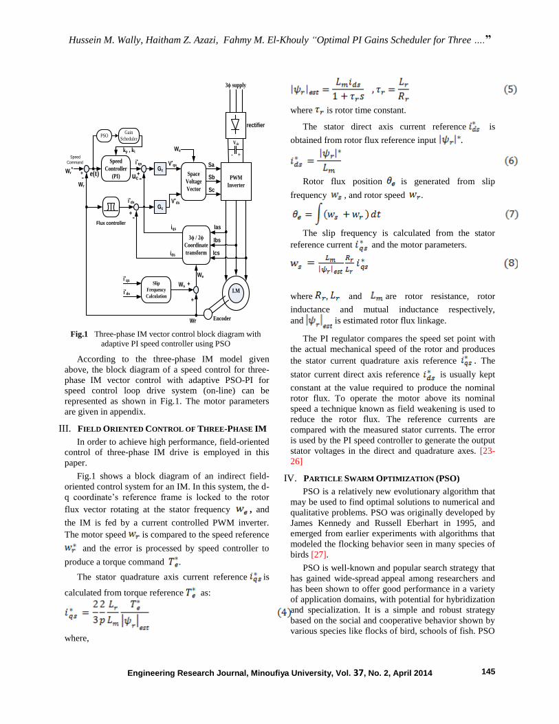
Fig.1 Three-phase IM vector control block diagram with
adaptive PI speed controller using PSO
According to the three-phase IM model given
above, the block diagram of a speed control for three-
phase IM vector control with adaptive PSO-PI for
speed control loop drive system (on-line) can be
represented as shown in Fig.1. The motor parameters
are given in appendix.
III. FIELD ORIENTED CONTROL OF THREE-PHASE IM
In order to achieve high performance, field-oriented
control of three-phase IM drive is employed in this
paper.
Fig.1 shows a block diagram of an indirect field-
oriented control system for an IM. In this system, the d-
q coordinate’s reference frame is locked to the rotor
flux vector rotating at the stator frequency , and
the IM is fed by a current controlled PWM inverter.
The motor speed is compared to the speed reference
and the error is processed by speed controller to
produce a torque command .
The stator quadrature axis current reference is
calculated from torque reference as:
where,
where is rotor time constant.
The stator direct axis current reference is
obtained from rotor flux reference input .
Rotor flux position is generated from slip
frequency , and rotor speed .
The slip frequency is calculated from the stator
reference current and the motor parameters.
where , and are rotor resistance, rotor
inductance and mutual inductance respectively,
and is estimated rotor flux linkage.
The PI regulator compares the speed set point with
the actual mechanical speed of the rotor and produces
the stator current quadrature axis reference . The
stator current direct axis reference is usually kept
constant at the value required to produce the nominal
rotor flux. To operate the motor above its nominal
speed a technique known as field weakening is used to
reduce the rotor flux. The reference currents are
compared with the measured stator currents. The error
is used by the PI speed controller to generate the output
stator voltages in the direct and quadrature axes. [23-
26]
IV. PARTICLE SWARM OPTIMIZATION (PSO)
PSO is a relatively new evolutionary algorithm that
may be used to find optimal solutions to numerical and
qualitative problems. PSO was originally developed by
James Kennedy and Russell Eberhart in 1995, and
emerged from earlier experiments with algorithms that
modeled the flocking behavior seen in many species of
birds [27].
PSO is well-known and popular search strategy that
has gained wide-spread appeal among researchers and
has been shown to offer good performance in a variety
of application domains, with potential for hybridization
and specialization. It is a simple and robust strategy
based on the social and cooperative behavior shown by
various species like flocks of bird, schools of fish. PSO
Hussein M. Wally, Haitham Z. Azazi, Fahmy M. El-Khouly “Optimal PI Gains Scheduler for Three ….”
Engineering Research Journal, Minoufiya University, Vol. 37, No. 2, April 2014 146
and its variants have been effectively applied to a wide
range of real-life optimization problems.
In simulations, birds would begin by flying around
with no particular destination and spontaneously
formed flocks until one of the birds flew over the
roosting area. Due to the simple rules, the birds used to
set their directions and velocities, a bird pulling away
from the flock in order to land at the roost would result
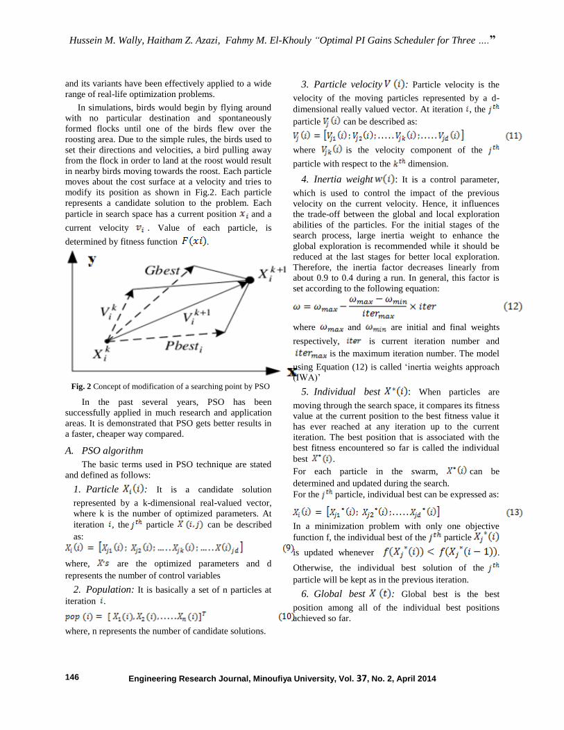
in nearby birds moving towards the roost. Each particle
moves about the cost surface at a velocity and tries to
modify its position as shown in Fig.2. Each particle
represents a candidate solution to the problem. Each
particle in search space has a current position and a
current velocity . Value of each particle, is
determined by fitness function .
Fig. 2 Concept of modification of a searching point by PSO
In the past several years, PSO has been
successfully applied in much research and application
areas. It is demonstrated that PSO gets better results in
a faster, cheaper way compared.
A. PSO algorithm
The basic terms used in PSO technique are stated
and defined as follows:
1. Particle : It is a candidate solution
represented by a k-dimensional real-valued vector,
where k is the number of optimized parameters. At
iteration , the particle can be described
as:
where, are the optimized parameters and d
represents the number of control variables
2. Population: It is basically a set of n particles at
iteration .
where, n represents the number of candidate solutions.
3. Particle velocity : Particle velocity is the
velocity of the moving particles represented by a d-
dimensional really valued vector. At iteration , the
particle can be described as:
where is the velocity component of the
particle with respect to the dimension.
4. Inertia weight : It is a control parameter,
which is used to control the impact of the previous
velocity on the current velocity. Hence, it influences
the trade-off between the global and local exploration
abilities of the particles. For the initial stages of the
search process, large inertia weight to enhance the
global exploration is recommended while it should be
reduced at the last stages for better local exploration.
Therefore, the inertia factor decreases linearly from
about 0.9 to 0.4 during a run. In general, this factor is
set according to the following equation:
where and are initial and final weights
respectively, is current iteration number and
is the maximum iteration number. The model
using Equation (12) is called ‘inertia weights approach
(IWA)’
5. Individual best : When particles are
moving through the search space, it compares its fitness
value at the current position to the best fitness value it
has ever reached at any iteration up to the current
iteration. The best position that is associated with the
best fitness encountered so far is called the individual
best .
For each particle in the swarm, can be
determined and updated during the search.
For the particle, individual best can be expressed as:
In a minimization problem with only one objective
function f, the individual best of the particle
is updated whenever .
Otherwise, the individual best solution of the
particle will be kept as in the previous iteration.
6. Global best : Global best is the best
position among all of the individual best positions
achieved so far.
Hussein M. Wally, Haitham Z. Azazi, Fahmy M. El-Khouly “Optimal PI Gains Scheduler for Three ….”
Engineering Research Journal, Minoufiya University, Vol. 37, No. 2, April 2014 147
7. Stopping criteria: Termination of the search
process will take place whenever one of the following
criteria is satisfied:
- The number of the iterations since the last
change of the best solution is greater than a
specified number.
- The number of iterations reaches the maximum
allowable number.
The particles are manipulated according to the
following equations:
1 1 2 2( ) ( )jd jd jd jd gd jdV V c r P X c r P X
(14)
jd jd jdX X V
(15)
where, g is the best particle among all particles, and
are positive constant and and are uniformly
distributed numbers in (0, 1).
B. Advantages of PSO
Many advantages of PSO over other traditional
optimization techniques can be summarized as follows:
PSO is a population-based search algorithm. This
property ensures PSO to be less susceptible in being
trapped on local minima. PSO makes use of the
probabilistic transition rules and not deterministic rules.
Hence, PSO is a kind of stochastic optimization
algorithm that can search for a complicated and
uncertain area. This makes PSO more flexible and
robust than conventional methods. PSO can easily deal
with non-differentiable objective functions because
PSO uses payoff (performance index or objective
function) information to guide the search in the
problem space. Additionally, this property relieves PSO
of assumptions and approximations, which are often
required by traditional optimization models. PSO has
the flexibility to control the balance between the global
and local exploration of the search space. This unique
feature of a PSO overcomes the premature convergence
problem and enhances the search capability which
makes it different from Genetic Algorithm (GA) and
other heuristic algorithms [27-30].
C. Parameter settings for the PSO algorithm
The proposed PSO based approach was
implemented using Intel core i3. 1.0 GHz processor
with 4 GB of RAM in MATLAB 10.0. Initially, several
runs have been done with different values of the PSO
key parameters such as inertia weight and the
maximum allowable velocity. Other parameters are
selected as a number of particles n=30, the iterations
=150, varied between (0.9 - 0.4) and the
cognitive and the social parameters and which
are be equalized , and & are
random numbers uniformly distributed within (0-1).
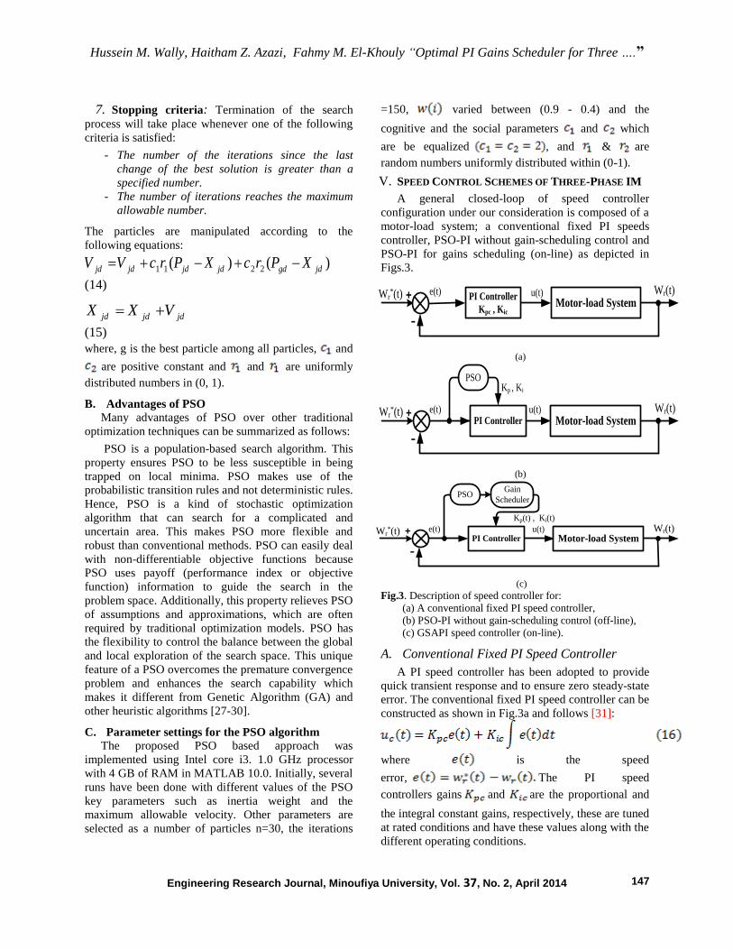
V. SPEED CONTROL SCHEMES OF THREE-PHASE IM
A general closed-loop of speed controller
configuration under our consideration is composed of a
motor-load system; a conventional fixed PI speeds
controller, PSO-PI without gain-scheduling control and
PSO-PI for gains scheduling (on-line) as depicted in
Figs.3.
Wr(t)Wr*(t)
��
+ e(t) u(t)Motor-load System
PI Controller
Kpc , Kic
(a)
Wr(t)Wr*(t)
��
+ e(t) u(t)
PSO
PI Controller Motor-load System
Kp , Ki
(b)
Gain
SchedulerPSO
Wr(t)Wr*(t)
��
+ e(t) u(t)PI Controller Motor-load System
Kp(t) , Ki(t)
(c)
Fig.3. Description of speed controller for:
(a) A conventional fixed PI speed controller,
(b) PSO-PI without gain-scheduling control (off-line),
(c) GSAPI speed controller (on-line).
A. Conventional Fixed PI Speed Controller
A PI speed controller has been adopted to provide
quick transient response and to ensure zero steady-state
error. The conventional fixed PI speed controller can be
constructed as shown in Fig.3a and follows [31]:
where is the speed
error, The PI speed
controllers gains and are the proportional and
the integral constant gains, respectively, these are tuned
at rated conditions and have these values along with the
different operating conditions.
Hussein M. Wally, Haitham Z. Azazi, Fahmy M. El-Khouly “Optimal PI Gains Scheduler for Three ….”
Engineering Research Journal, Minoufiya University, Vol. 37, No. 2, April 2014 148
B. Particle Swarm Optimization (PSO)
PSO is suggested by Eberhart and Kennedy in 1995
based on the analogy of swarm of bird and school of
fish as mentioned before. The PSO mimics the
behavior of individuals in a swarm to maximize the
survival of the species. The main advantages of the
PSO algorithm over other heuristic optimization
techniques are summarized as; simple concept, easy
implementation, robustness to control parameters,
computational efficiency, lower sensitivity to the nature
of the objective function and derivative free property
unlike many conventional techniques as shown in
Fig.3b [30]. An optimal control scheme based PSO
Algorithm method is used for tuning the parameters of
PI controller. The PSO algorithm is used to search an
optimal parameter set containing Kp and Ki. The
parameters used for tuning the PSO algorithm and
Simulink parameters are tabulated in Table.3 and in
section IV(C) mentioned above [32].
C. Gain Scheduling Adaptive PI Controller
[GSAPI]
Gain scheduling method is applied to three-phase
IM for online tuning of the PI speed controller in
presence of set point changes which obtaining the
parameter of the speed controller gains using PSO
optimization. It is counted as an adaptive method and
offers a robust performance. The structure of this
method has the ability of online tuning of the proposed
PI with respect to time. It is also robust in presence of
system uncertainties [33].
In this study, PI gain scheduling model structure is
offered as shown as in Fig.3c by using PSO techniques.
GSAPI used to solve the problems of other tuning
methods, in order to meet the control objectives and to
provide high performance of the drive.
The key feature of the proposed gain scheduling
scheme of adaptive control is the reduced amount of
computation. An easy and low cost practical
implementation of the procedure is possible without
employing expensive dedicated computing systems.
This scheme is very easy to implement in practice since
an existing PI speed controller is tuned automatically to
control fast transient recovery and low overshoot in the
dynamic response of the system. In this scheme, the
gains are allowed to vary over a predetermined range
for varying operating conditions. The gain scheduled
PI speed controller output, which is considered as the
reference torque of the motor can be described as:
where and are the proportional and the
integral variable gains, respectively. These gains are
obtained by using PSO techniques.
VI. SIMULATION RESULTS
The control algorithm of the control methods has
been developed and simulated using the
MATLAB/SIMULINK software based on the
introduced mathematical model. The performance of
the three-phase IM drive system is tested under
different operating conditions. Simulation results
include starting operation, step speed command, speed
reversal and load impact. The performance of a gain-
scheduling adaptive of a PI speed controller in
comparison with conventional fixed PI and PSO-PI
speed controllers is examined and assessed by
computer simulations. The system parameters are
reported in appendix.
0 1 2 3 4 5 6 7 8 9 10-50
0
50
100
150
200
Time (sec)
Mo
to
r S
peed
( r
ad
/sec )
4.95 5 5.05 5.1 5.15 5.2 5.2548
49
50
51
52
5 5.1 5.2 5.3 5.4
48
49
50
51
52
53
5.9 6 6.1 6.2 6.3 6.4
36.5
37
37.5
38
38.5
39
1.4 1.6 1.8 2 2.2
149
150
151
152
153
154
3 3.5 4 4.5
290
300
310
320
330
3 3.5 4 4.5290
300
310
320
330
3.5 4 4.5 5290
300
310
320
330
PIPSO
GSAPI
(a)
0 1 2 3 4 5 6 7 8 9 10
-20
0
20
40
60
Time (sec)
Mo
to
r T
orq
ue
( N
.m )
1.45 1.5 1.55 1.6 1.65 1.7
6.6
6.8
7
7.2
7.4
7.6
4.95 5 5.05
5.5
6
6.5
7
7.5
6.98 7 7.02 7.04 7.06 7.08
7
8
9
10
11
3 3.05 3.1
5.5
6
6.5
7
7.5
PIPSO
GSAPI
(b)
Hussein M. Wally, Haitham Z. Azazi, Fahmy M. El-Khouly “Optimal PI Gains Scheduler for Three ….”
Engineering Research Journal, Minoufiya University, Vol. 37, No. 2, April 2014 149
0 1 2 3 4 5 6 7 8 9 10
-50
0
50
100
Time (sec)
Mo
to
r S
peed
E
rro
r ( ra
d/sec )
2.5 3 3.5 4 4.5 5 5.5 6 6.5-1
0
1
2
3
7 7.2 7.4 7.6 7.8
-4
-2
0
2
4
GSAPI
PSO
PI
(c)
0 1 2 3 4 5 6 7 8 9 100
5
10
15
Time (sec)
Kp
&
K
i
Ki
Kp
(d)
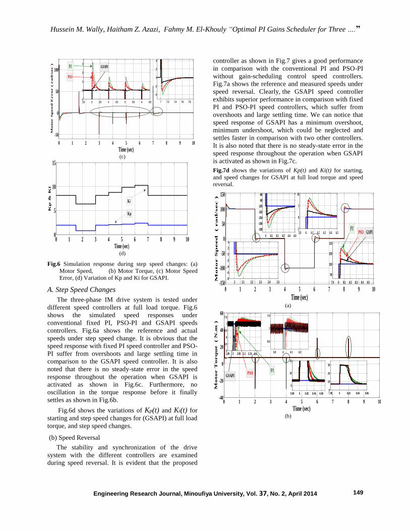
Fig.6 Simulation response during step speed changes: (a)
Motor Speed, (b) Motor Torque, (c) Motor Speed
Error, (d) Variation of Kp and Ki for GSAPI.
A. Step Speed Changes
The three-phase IM drive system is tested under
different speed controllers at full load torque. Fig.6
shows the simulated speed responses under
conventional fixed PI, PSO-PI and GSAPI speeds
controllers. Fig.6a shows the reference and actual
speeds under step speed change. It is obvious that the
speed response with fixed PI speed controller and PSO-
PI suffer from overshoots and large settling time in
comparison to the GSAPI speed controller. It is also
noted that there is no steady-state error in the speed
response throughout the operation when GSAPI is
activated as shown in Fig.6c. Furthermore, no
oscillation in the torque response before it finally
settles as shown in Fig.6b.
Fig.6d shows the variations of Kp(t) and Ki(t) for
starting and step speed changes for (GSAPI) at full load
torque, and step speed changes.
(b) Speed Reversal
The stability and synchronization of the drive
system with the different controllers are examined
during speed reversal. It is evident that the proposed
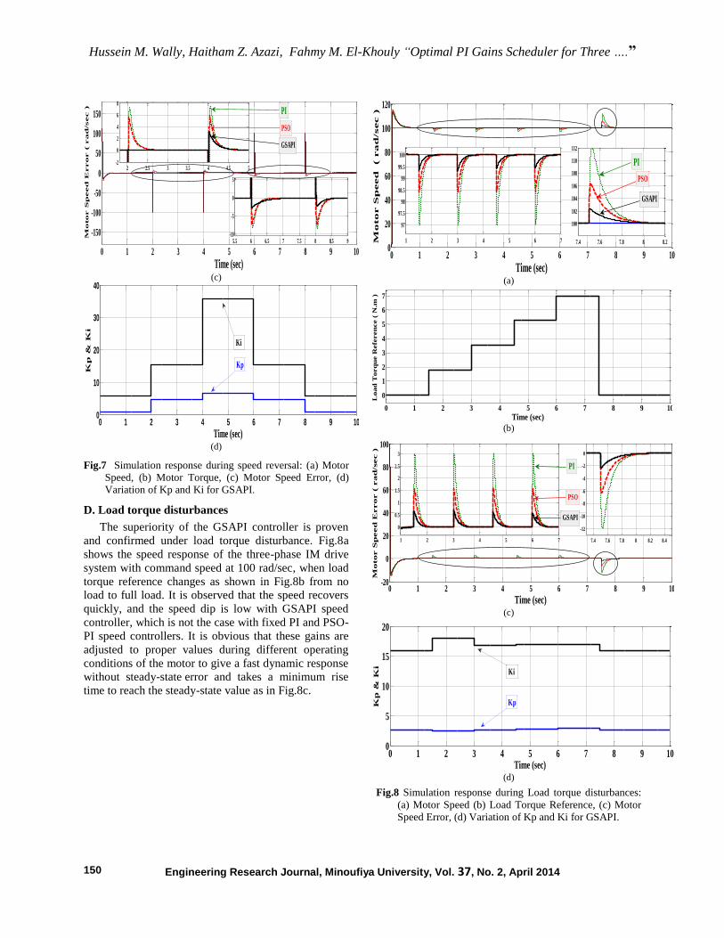
controller as shown in Fig.7 gives a good performance
in comparison with the conventional PI and PSO-PI
without gain-scheduling control speed controllers.
Fig.7a shows the reference and measured speeds under
speed reversal. Clearly, the GSAPI speed controller
exhibits superior performance in comparison with fixed
PI and PSO-PI speed controllers, which suffer from
overshoots and large settling time. We can notice that
speed response of GSAPI has a minimum overshoot,
minimum undershoot, which could be neglected and
settles faster in comparison with two other controllers.
It is also noted that there is no steady-state error in the
speed response throughout the operation when GSAPI
is activated as shown in Fig.7c.
Fig.7d shows the variations of Kp(t) and Ki(t) for starting,
and speed changes for GSAPI at full load torque and speed
reversal.
0 1 2 3 4 5 6 7 8 9 10-150
-100
-50
0
50
100
150
Time (sec)
Mo
to
r S
peed
( ra
d/sec )
7.9 8 8.1 8.2 8.3 8.4 8.5
95
100
105
110
4 4.1 4.2 4.3 4.4 4.5
-108
-106
-104
-102
-100
-98
-96
2 2.1 2.2 2.3 2.4 2.5-8
-6
-4
-2
0
2
4
5.9 6 6.1 6.2 6.3 6.4 6.5-5
0
5
10
GSPIPSOPI
(a)
0 1 2 3 4 5 6 7 8 9 10-40
-20
0
20
40
60
Time (sec)
Mo
to
r T
orq
ue ( N
.m
)
1.95 2 2.05 2.1 2.15 2.25
5.5
6
6.5
7
7.5
5.98 6 6.02 6.04 6.06
5
10
15
3.9 4 4.1 4.2
6.5
7
7.5
6.2 6.447.647.84848.248.448.648.8
7.98 8 8.02 8.04 8.060
10
20
30
0 0.5 1 1.5150
155
160
165
PIPSO
GSAPI
(b)
Hussein M. Wally, Haitham Z. Azazi, Fahmy M. El-Khouly “Optimal PI Gains Scheduler for Three ….”
Engineering Research Journal, Minoufiya University, Vol. 37, No. 2, April 2014 150
0 1 2 3 4 5 6 7 8 9 10
-150
-100
-50
0
50
100
150
Time (sec)
Mo
to
r S
peed
E
rro
r ( ra
d/sec )
2 2.5 3 3.5 4 4.5 5-2
0
2
4
6
8
5.5 6 6.5 7 7.5 8 8.5 9-10
-5
0
5
PI
PSO
GSAPI
(c)
0 1 2 3 4 5 6 7 8 9 100
10
20
30
40
Time (sec)
Kp
&
K
i
Ki
Kp
(d)
Fig.7 Simulation response during speed reversal: (a) Motor
Speed, (b) Motor Torque, (c) Motor Speed Error, (d)
Variation of Kp and Ki for GSAPI.
D. Load torque disturbances
The superiority of the GSAPI controller is proven
and confirmed under load torque disturbance. Fig.8a
shows the speed response of the three-phase IM drive
system with command speed at 100 rad/sec, when load
torque reference changes as shown in Fig.8b from no
load to full load. It is observed that the speed recovers
quickly, and the speed dip is low with GSAPI speed
controller, which is not the case with fixed PI and PSO-
PI speed controllers. It is obvious that these gains are
adjusted to proper values during different operating
conditions of the motor to give a fast dynamic response
without steady-state error and takes a minimum rise
time to reach the steady-state value as in Fig.8c.
0 1 2 3 4 5 6 7 8 9 100
20
40
60
80
100
120
Time (sec)
Mo
to
r S
peed
( ra
d/sec )
1 2 3 4 5 6 7
97
97.5
98
98.5
99
99.5
100
7.4 7.6 7.8 8 8.2
100
102
104
106
108
110
112
PI
PSO
GSAPI
(a)
0 1 2 3 4 5 6 7 8 9 10
0
1
2
3
4
5
6
7
Time (sec)
Load
Torq
ue R
efe
ren
ce (
N.m
)
(b)
0 1 2 3 4 5 6 7 8 9 10-20
0
20
40
60
80
100
Time (sec)
Motor S
peed
Error (
rad
/sec )
7.4 7.6 7.8 8 8.2 8.4
-12
-10
-8
-6
-4
-2
0
1 2 3 4 5 6 7
0
0.5
1
1.5
2
2.5
3
GSAPI
PSO
PI
(c)
0 1 2 3 4 5 6 7 8 9 100
5
10
15
20
Time (sec)
Kp
& K
i
Ki
Kp
(d)
Fig.8 Simulation response during Load torque disturbances:
(a) Motor Speed (b) Load Torque Reference, (c) Motor
Speed Error, (d) Variation of Kp and Ki for GSAPI.
Hussein M. Wally, Haitham Z. Azazi, Fahmy M. El-Khouly “Optimal PI Gains Scheduler for Three ….”
Engineering Research Journal, Minoufiya University, Vol. 37, No. 2, April 2014 151
Fig.8d shows the variations of Kp(t) and Ki(t) for
starting, transient conditions and load disturbance for
GSAPI at speed constant.
It is noted that, overall dynamic performances
of the motor when operated at the GSAPI speed
controller with PSO is better than the
conventional PI and PSO-PI speed controllers,
and the steady-state error of speed response is
zero. Simulation results indicate that controllers
designed using PSO approach guarantees good
performance under various load conditions.
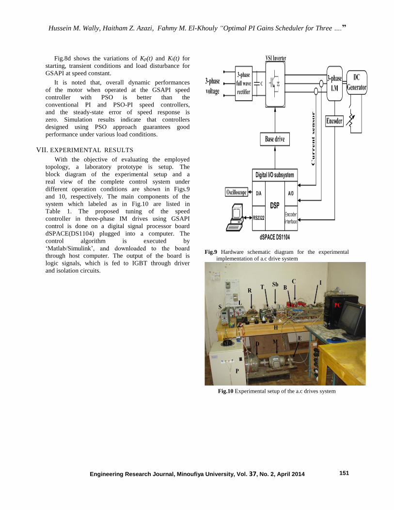
VII. EXPERIMENTAL RESULTS
With the objective of evaluating the employed
topology, a laboratory prototype is setup. The
block diagram of the experimental setup and a
real view of the complete control system under
different operation conditions are shown in Figs.9
and 10, respectively. The main components of the
system which labeled as in Fig.10 are listed in
Table 1. The proposed tuning of the speed
controller in three-phase IM drives using GSAPI
control is done on a digital signal processor board
dSPACE(DS1104) plugged into a computer. The
control algorithm is executed by
‘Matlab/Simulink’, and downloaded to the board
through host computer. The output of the board is
logic signals, which is fed to IGBT through driver
and isolation circuits.
Fig.9 Hardware schematic diagram for the experimental
implementation of a.c drive system
Fig.10 Experimental setup of the a.c drives system
Hussein M. Wally, Haitham Z. Azazi, Fahmy M. El-Khouly “Optimal PI Gains Scheduler for Three ….”
Engineering Research Journal, Minoufiya University, Vol. 37, No. 2, April 2014 152
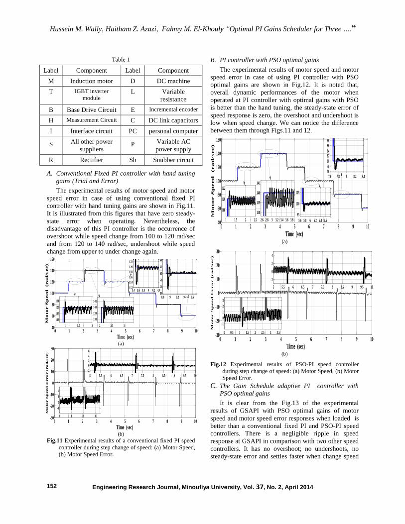
Table 1
Label Component Label Component
M Induction motor D DC machine
T IGBT inverter
module L Variable
resistance
B Base Drive Circuit E Incremental encoder
H Measurement Circuit C DC link capacitors
I Interface circuit PC personal computer
S All other power
suppliers P Variable AC
power supply
R Rectifier Sb Snubber circuit
A. Conventional Fixed PI controller with hand tuning
gains (Trial and Error)
The experimental results of motor speed and motor
speed error in case of using conventional fixed PI
controller with hand tuning gains are shown in Fig.11.
It is illustrated from this figures that have zero steady-
state error when operating. Nevertheless, the
disadvantage of this PI controller is the occurrence of
overshoot while speed change from 100 to 120 rad/sec
and from 120 to 140 rad/sec, undershoot while speed
change from upper to under change again.
0 1 2 3 4 5 6 7 8 9 1040
60
80
100
120
140
160
Time (sec)
Mo
to
r S
peed
(ra
d/sec)
3.4 3.6 3.8 4 4.2 4.4112
114
116
118
120
122
8.8 9 9.2 9.4 9.654
56
58
60
62
64
2 2.5 3
138
139
140
141
1 1.5 2
118
119
120
121
(a)
0 1 2 3 4 5 6 7 8 9 10-30
-20
-10
0
10
20
30
Time (sec)
Mo
to
r S
peed
E
rro
r (ra
d/sec)
0 1 2 3
-1
0
1
2
5 5.5 6 6.5 7 7.5 8 8.5 9 9.5 10
-2
0
2
4
6
(b)
Fig.11 Experimental results of a conventional fixed PI speed
controller during step change of speed: (a) Motor Speed,
(b) Motor Speed Error.
B. PI controller with PSO optimal gains
The experimental results of motor speed and motor
speed error in case of using PI controller with PSO
optimal gains are shown in Fig.12. It is noted that,
overall dynamic performances of the motor when
operated at PI controller with optimal gains with PSO
is better than the hand tuning, the steady-state error of
speed response is zero, the overshoot and undershoot is
low when speed change. We can notice the difference
between them through Figs.11 and 12.
0 1 2 3 4 5 6 7 8 9 1040
60
80
100
120
140
160
Time (sec)
Mo
to
r S
peed
(ra
d/sec)
2.6 2.8 3 3.2 3.4 3.6 3.8
138
139
140
141
5.6 5.8 6 6.2 6.4 6.6
95
100
105
7.6 7.8 8 8.2 8.476
78
80
8284
86
88
1 1.5 2 2.5
118
120
122
(a)
0 1 2 3 4 5 6 7 8 9 10-30
-20
-10
0
10
20
30
Time (sec)
Motor S
peed
E
rror (rad
/sec)
0 0.5 1 1.5 2 2.5 3 3.5
-1
0
1
2
3
5 5.5 6 6.5 7 7.5 8 8.5 9 9.5 10
-2
0
2
4
(b)
Fig.12 Experimental results of PSO-PI speed controller
during step change of speed: (a) Motor Speed, (b) Motor
Speed Error.
C. The Gain Schedule adaptive PI controller with
PSO optimal gains
It is clear from the Fig.13 of the experimental
results of GSAPI with PSO optimal gains of motor
speed and motor speed error responses when loaded is
better than a conventional fixed PI and PSO-PI speed
controllers. There is a negligible ripple in speed
response at GSAPI in comparison with two other speed
controllers. It has no overshoot; no undershoots, no
steady-state error and settles faster when change speed

Hussein M. Wally, Haitham Z. Azazi, Fahmy M. El-Khouly “Optimal PI Gains Scheduler for Three ….”
Engineering Research Journal, Minoufiya University, Vol. 37, No. 2, April 2014 153
from 100 to 120 rad/sec and from 120 to 140 rad/ sec
and return again.
0 1 2 3 4 5 6 7 8 9 1040
60
80
100
120
140
160
Time (sec)
Mo
to
r S
peed
(ra
d/sec)
7.5 8 8.5 9
79
80
81
82
6 6.5 7
98
100
102
0.5 1 1.5 2 2.5
118
119
120
121
2.6 2.8 3 3.2 3.4 3.6 3.8
138
139
140
141
(a)
0 1 2 3 4 5 6 7 8 9 10-30
-20
-10
0
10
20
30
Time (sec)
Motor S
peed
E
rror (rad
/sec)
0 0.5 1 1.5 2 2.5 3 3.5 4
-1
0
1
2
4 5 6 7 8 9 10-4
-2
0
2
(b)
Fig.13 Experimental results using GSAPI speed controller
during step change of speed: (a) Motor Speed, (b) Motor
Speed Error.
The benefits of the proposed GSAPI regulator in
settling time and performance are validated by
comparing Fig.13 with Fig.11 and 12, which shows the
performance of the same three-phase IM drive with
conventional speed PI; PSO-PI and GSAPI speed
controllers.
This means that the GSAPI parameters are adjusted
according to the speed and load torque conditions in
order to meet the control objectives and to provide high
performance of the drive. The gain of the controllers
can be set to control fast transient recovery and low
overshoot in the dynamic response of the system.
GSAPI controller improves steady-state error with little
or no overshoot.
Table 3 and 4 summarizes the simulation and
experimental results of all three cases of the adaptive
control method GSAPI compared with the conventional
fixed PI and PSO-PI without gain-scheduling control
speed controllers.
VIII. CONCLUSIONS
A gain scheduling adaptive PI controller for a three-
phase IM drive using PSO has been presented in this
paper. The three-phase IM drive system has been
examined experimentally and by computer simulations
with proposed controller, conventional fixed PI and
PSO-PI. The gains of the proposed controller have been
varied and tuned such that the drive system exhibits
satisfactory transient and steady-state response under
varying operating conditions. Simulation and
experimental results show the effectiveness of this
approach and demonstrate the usefulness of the
proposed controller in high-performance drives. The
proposed controller method has shown a good
performance in comparison with the conventional fixed
PI and PSO-PI controllers in terms of speed varied and
load disturbances. Furthermore, the proposed method
has characterized by simplicity, low computation time
and ease of implementation. A comparison between the
conventional fixed PI, PSO-PI controllers and a GSAPI
one has shown the advantages of the proposed scheme.
REFERENCES
[1] G. K. Singh, K. Nam and S. K. Lim, “A Simple
Indirect Field-Oriented Control Scheme for
Multiphase Induction Machine” IEEE Transactions
on Industrial Electronics Society, Vol. 52, No. 4,
pp. 1177 - 1184 Aug 2005.
[2] R. Thangaraj, Th. R. Chelliah, M. Pant and A.
Abraham, C. Grosan, "Optimal gain tuning of PI
speed controller in induction motor drives using
particle swarm optimization", Oxford Journals,
Mathematics & Physical Sciences, Logic Journal of
the IGPL, Vol 19, No. 2, pp. 343-356, July 2010.
[3] S. Subramanian, R. Bhuvaneswari and V.P.
Sakthivel, "An Improved Particle Swarm
Optimization for Induction Motor Parameter
Determination" International Journal of Computer
Applications, Vol. 1, No. 2, pp. 62-67, 2010.
[4] V. Chitra and R. S. Prabhakar, "Induction
Motor Speed Control using Fuzzy Logic
Controller", World Academy of Science,
Engineering and Technology 23, pp. 17-22,
2006.
[5] M. S. Zaky and E. M. Ismaeil "Gain
Scheduling Adaptive PI Control of Hybrid
Stepper Motor Drives Stepper Motor Drives"
Electrical Power Components and systems,
No. 121, pp. 85-91, Dec 2010.
Hussein M. Wally, Haitham Z. Azazi, Fahmy M. El-Khouly “Optimal PI Gains Scheduler for Three ….”
Engineering Research Journal, Minoufiya University, Vol. 37, No. 2, April 2014 154
[6] A. Besharati, W. Lo and K. M Tsang, "Self-tuning
PID controller using Newton-Raphson Search
Method", IEEE Transactions on Power Electronics.
Vol. 44, No. 5, pp. 717-725, Oct 1997.
[7] Y. del Valle, G.K. Venayagamoorthy, S.
Mohagheghi, J.C. Hernandez, and R.G.
Harley, "Particle Swarm Optimization: Basic
Concepts, Variants and Applications in Power
Systems", IEEE Transactions on Evolutionary
Computation, Vol. 12, No. 2, pp. 171-195,
Apr 2008.
[8] M.A. Porta García, O. Montiel, O. Castillo and R.
Sepúlveda. “Optimal Path Planning for
Autonomous Mobile Robot Navigation Using Ant
Colony Optimization and a Fuzzy Cost Function
Evaluation” Springer-Verlag Berlin Heidelberg,
Analysis and Design of Intelligent Systems using
Soft Computing Techniques, pp. 790–798, 2007.
[9] R. L. Haupt and S. E. Haupt, "Practical genetic
algorithms" 2nd edition, published by John
Wiley & Sons, Inc., Hoboken, New Jersey,
2004.
[10] S. Panda and N. P. Padhy, "Comparison of
particle swarm optimization and genetic
algorithm for FACTS-based controller
design", Applied Soft Computing,
ELSEVIER, Vol. 8, No. 4, pp. 1418–1427,
Sep 2008.
[11] M. Peyvandi, M. Zafarani and E. Nasr,
"Comparison of Particle Swarm Optimization
and the Genetic Algorithm in the Improvement
of Power System Stability by an SSSC-based
Controller", Journal of Electrical Engineering
& Technology, Vol. 6, No. 2, pp. 182-191,
2011.
[12] H. Azarkish, S. Farahat, and S.Masoud H.
Sarvari, "Comparing the Performance of the
Particle Swarm Optimization and the Genetic
Algorithm on the Geometry Design of
Longitudinal Fin", World Academy of
Science, Engineering and Technology 61, pp.
836-9, 2012.
[13] S. Panda and N. P. Padhy, "Comparison of Particle
Swarm Optimization and Genetic Algorithm for
TCSC-based Controller Design", International
Journal of Electrical and Electronics Engineering
1:5, pp. 305-313, 2007.
[14] G. Orelind, L. Wozniak, J. Medanic, and T.
Whittemore, “Optimal PID gain schedule for
hydrogenerators-Design and applications,” IEEE
Trans. Energy Convers., Vol. 4, No. 3, pp. 300-307,
Sep. 1989.
[15] M. R. Mataušek, B. I. Jefteniæ, D. M. Miljkoviæ,
and M. Z. Bebiæ, “Gain scheduling control of DC
motor drive with field weakening,” IEEE Trans.
Ind. Electron., Vol. 43, No. 1, pp. 153-162, Feb.
1996.
[16] A. Kumar, A. Kumar and S. Chanana " Genetic
Fuzzy PID Controller Based on Adaptive Gain
Scheduling for Load Frequency Control" IEEE,
Power Electronics, Drives and Energy Systems
(PEDES)& 2010 Power India, 2010 Joint
International Conference, pp. 1-8, Dec 2010 .
[17] J. Talaq and F. Al-Basri, “Adaptive fuzzy gain
scheduling for load frequency control,” IEEE Trans.
Power Syst., vol. 14, no. 1, pp. 145-150, Feb. 1999.
[18] Ch. Mademlis, and I. Kioskeridis " Gain-
Scheduling Regulator for High-Performance
Position Control of Switched Reluctance Motor
Drives" IEEE transactions on industrial electronics,
pp. 2922-2931, Vol. 57, No. 9, Sep 2010.
[19] S. K. Panda, X. M. Zhu, and P. K. Dash, “Fuzzy
gain scheduled PI speed controller for switched
reluctance motor drive,” in Proc. IEEE IECON,
Vol. 3, pp. 989–994, Nov 1997.
[20] B. Ozpineci, L. M. Tolbert “Simulink
Implementation of Induction Machine Model”,
IEEE conference publications, Vol. 2, pp. 728
- 734 , 2003.
[21] Ae. Mahesh, Dr. Ba Singh “Vector Control of
Induction Motor Using ANN and Particle Swarm
Optimization” UETAE, International Journal of
Emerging Technology and Advanced Engineering, pp. 480-485, Vol. 2, No. 9, Sept 2012.
[22] M. M. Eissa, G. S. Virk, A. M. AbdelGhany,
E. S. Ghith, “Optimum Induction Motor Speed
Control Technique Using Particle Swarm
Optimization” Scientific & Academic
Publishing, International Journal of Energy
Engineering, Vol. 3, No. 2, pp. 65-73, 2013.
[23] G-W. Chang, G. Espinosa-Pérez, E. Mendes, and
R. Ortega "Tuning Rules for the PI Gains of Field-
Oriented Controllers of Induction Motors" IEEE
Transactions on Industrial Electronics, pp. 592-602,
Vol. 47, NO. 3, Jun 2000.
[24] E. Ozkop, H.I. Okumus “Direct Torque Control of
Induction Motor Using Space Vector Modulation
(SVM-DTC)" IEEE, Power System Conference,
MEPCON 2008, 12th International Middle-East, pp.
368 – 372, Mar 2008.
[25] G. S. Buja, and M. P. Kazmierkowski, "Direct
Torque Control of PWM Inverter-Fed AC Motors-A
Survey", IEEE, Transactions on Industrial
Electronics, Vol. 51, No. 4, pp. 744-757, Aug. 2004.
[26] D. Casadei, F. Profumo, G. Serra, and A. Tani
"FOC and DTC: Two Viable Schemes for Induction
Motors Torque Control" IEEE transactions on
Hussein M. Wally, Haitham Z. Azazi, Fahmy M. El-Khouly “Optimal PI Gains Scheduler for Three ….”
Engineering Research Journal, Minoufiya University, Vol. 37, No. 2, April 2014 155
power electronics, Vol. 17, No. 5, pp. 779-787, Sep.
2002.
[27] J, Kennedy, R, Eberhart, "Particle Swarm
Optimization." Proc. IEEE Int. Conf. Neural
Networks. 4, pp. 1942-48, 1995.
[28] M. B. B. Sharifian, S. Galvani and M. B.
Kouhshahi, "Torque fluctuations reducing in a
vector-controlled induction motor drive by PI
controller tuning using particle swarm
optimization" IEEE, International Conference on
Electrical Machines and Systems (ICEMS), pp. 1-6,
Aug 2011.
[29] V.P. Sakthivel, R. Bhuvaneswari and S.
Subramanian “Adaptive Particle Swarm
Optimization for the Design of Three-Phase
Induction Motor Considering the Active
Power Loss Effect” IACSIT, International
Journal of Computer and Electrical
Engineering, Vol. 2, No. 4, pp. 627-636, Aug,
2010.
[30] M. Mahdavi and H. Monsef “advanced Particle
Swarm Optimization used for optimal design of
single-phase induction motor” (IJTPE),
International Journal on, “Technical and Physical
Problems of Engineering” Vol. 2, No. 1, pp. 55-59,
Mar 2010.
[31] M. Pant, R. Thangaraj, and A. Abraham,
"Optimal tuning of PI speed controller using
nature inspired heuristics", IEEE Computer
Society, In Proceedings of the Eighth
International Conference on Intelligent
Systems Design and Applications, pp. 420-
425, Nov 2008.
[32] R. Jayanthi, I. A. Chidambaram, C. Banusri
"Decentralized controller gain scheduling using
PSO for power system restoration assessment in a
two-area interconnected power system"
International Journal of Engineering, Science and
Technology, Vol. 3, No. 4, pp. 14-26, 2011.
[33] M. A. Movahed, A. M. Yazdani, "Application of
Imperialist Competitive Algorithm in Online PI
Controller" IEEE, 2011 Second International
Conference on Intelligent Systems, Modelling and
Simulation (ISMS), pp. 83-87, Jan. 2011.
APPENDIX
The simulation and the experimental results for the
proposed method are taken with the following
specifications:
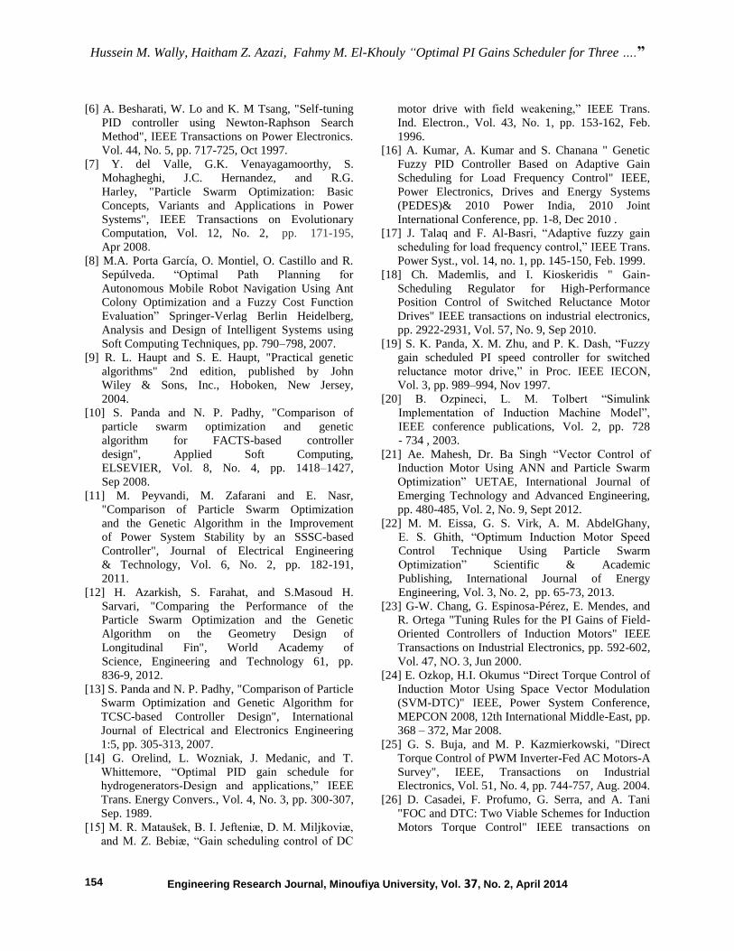
Table 2
The induction motor parameters are as follows:
Rated power 1.5 HP
Rated voltage 380 V
Rated current 2-8 A
No. of poles 4
Stator resistance 7.4826 Ω
Rotor resistance 3.834 Ω
Mutual inductance 0.4114 H
Stator leakage inductance 0.0221 H
Rotor leakage inductance 0.0221 H
Rated speed 1400 rpm
Moment of inertia 0.035 kg.m2
Rated torque 7.5 N.m
Table 3
Gains of conventional PI and PSO-PI (off-line)
controllers
a conventional fixed PI PSO-PI (off-line)
KPc 0.5 KPpso 1.0143
Kic 4 KIpso 7.1623
Table 4
Gains of GSAPI speed controller
Wr
rad/sec
TL
N.m
KP KI Wr
rad/sec
TL
N.m
KP KI
150
0 2.5501 15.3058
50
0 1.0134 7.1623
1.75 2.7851 17.0301 1.75 5.3254 28.3254
3.5 2.9853 17.805 3.5 5.4408 30.4563
5.25 2.9853 17.8315 5.25 5.5542 30.5468
7 3.0214 17.9094 7 5.9898 33.8245
100
0 2.6899 15.9958
37.5
0 3.0578 19.0623
1.75 2.5035 18.101 1.75 6.1578 30.9554
3.5 2.5954 16.8795 3.5 6.3212 31.0663
5.25 2.7120 16.9515 5.25 6.4625 31.6653
7 2.9225 17.0094 7 6.6045 35.0658
75
0 3.5486 23.2645
-100
0 0.9073 5.6958
1.75 4.0852 23.3209 1.75 2.0254 9.5487
3.5 4.6025 23.6825 3.5 4.7853 15.4015
5.25 4.6320 23.8315 5.25 6.5123 35.7714
7 4.6457 23.9094 7 7.2105 38.5478


![Computer Architecture and Assembly Languagecaspl162/wiki.files/PS07_162[1].pdf · main() scheduler co-routine1 scheduler co-routine2 scheduler ... • flags • stack pointer (ESP)](https://img.pdfslide.us/doc/110x75/5b8a0ca57f8b9a50388b4848/computer-architecture-and-assembly-language-caspl162wikifilesps071621pdf.jpg)