Embed Size (px)
Citation preview

Ocean Engineering 46 (2012) 33–45
Contents lists available at SciVerse ScienceDirect
Ocean Engineering
0029-80
doi:10.1
n Corr
E-m
psotirop1 Pr
Departm
journal homepage: www.elsevier.com/locate/oceaneng
Optimal docking pose and tactile hook-localisation strategy for AUVintervention: The DIFIS deployment case
Panagiotis Sotiropoulos a,n,1, Niccolo Tosi b, Fivos Andritsos a, Franck Geffard b
a European Commission, Joint Research Centre, IPSC, Ispra,VA 21027, Italyb CEA, LIST, Interactive Robotics Laboratory, Fontenay-aux-Roses, F-92265, France
a r t i c l e i n f o
Article history:
Received 2 December 2010
Accepted 20 February 2012
Editor-in-Chief: A.I. Incecikwell-blow-out cases such as the recent accident in the Gulf of Mexico. The DIFIS deployment typically
requires the use of ROVs and dedicated dynamic-positioning ships that increase the cost significantly
Available online 22 March 2012Keywords:
Autonomous underwater vehicles
Docking
Tactile localisation
Manipulation
Underwater operations
18/$ - see front matter & 2012 Elsevier Ltd. A
016/j.oceaneng.2012.02.005
esponding author. Tel.: þ390332785358.
ail addresses: [email protected]
@mech.upatras.gr (P. Sotiropoulos).
esent Address: University of Patras, Mechanic
ent, Rio 26504, Greece. Tel.: þ30261099614
a b s t r a c t
The DIFIS project has proposed a new solution for the immediate intervention directly on tanker wrecks
so as to contain any leakages and prevent eventual pollution. The method could be extended also to oil
and make the operations weather-dependent. Eventual AUV use would result in much more efficient
and flexible deployment procedures. The scenario studied here consists of a hook-grasping task that is
part of the DIFIS mooring procedure. The overall objective is to automate certain processes enabling the
use of AUVs or, at least, enhancing the currently foreseen ROV operations. A two-step method is
presented consisting of a genetic algorithm for the determination of the optimum docking pose for the
vehicle, and a particle filter algorithm that runs on a later stage for the tactile localisation of the hook.
The method proposed is rather generic and can be extended to several steps of the DIFIS Deployment
procedure, or even to other AUV intervention missions in a semi-structured environment. Results from
the two algorithms are also presented and discussed.
& 2012 Elsevier Ltd. All rights reserved.
1. Introduction
The increasing oil and gas demand is forcing oil companies toexplore new drilling areas leading offshore platforms to sites ofconstantly bigger depths, several kilometres below the sea sur-face, with all the related risks. Blowouts such as the one in theGulf of Mexico in May 2010 cannot be excluded. Regulations andnew methods of prompt containment interventions at the seabed,right at the source of the pollution, will be required for sustain-able offshore hydrocarbon exploitation.
Triggered from another recent catastrophe, that of the PRESTIGE,the DIFIS (Double Inverted Funnel for Intervention System) projectproposed a new solution to deal with tanker wrecks and preventingenvironmental disasters (DIFIS; Andritsos et al., 2007, 2008; Cozijnet al., 2008; Konstantinopoulos and Andritsos, 2008). The basicconcept relies on gravity forces to channel the flux of spilt fueltowards the surface. Leaking fuel is collected by a moored fabricdome covering the wreck and channelled through a large riser tubeto an open inverted reservoir, the buffer bell, 20–30 m below the seasurface. The buffer bell serves for buffer storage, as a separator and,through its buoyancy, keeps the whole system in tension. Fig. 1
ll rights reserved.
uropa.eu,
al and Aeronautics Engineers
2.
shows an initial conceptual model of the dome and the buffer bell.DIFIS, with some re-engineering to take account of the methane gas,can be applied to contain deep sea oil well blow-out accidents.
DIFIS system has many advantages: it is simple, entirelypassive (apart from the periodical off-loading of the collected oilfrom the buffer bell), once installed does not require operationswith Remotely Operated Vehicle’s (ROVs) and it is rough weathertolerant. However, its deployment requires substantial prepara-tion and intense underwater remote manipulation activitiessupported by specialised equipment and dynamic positioning(DP) vessels. This represents a significant part of its overall cost.
Optimising the deployment procedures and, in particular, usingIntervention-Autonomous Underwater Vehicles (I-AUVs) instead ofROV-based activities would decrease the overall DIFIS interventioncost and add substantially to its flexibility. I-AUVs possess certainadvantages such as the significant reduction of the size of the supportvessel, while no DP vessel is needed, and the fact that it is notrequired to remain on site for the entire mission. Thus, the cost of themission is reduced accordingly. Moreover, since I-AUVs can operateuntethered, their deployment can be immediate regardless of the sea-state on site, while such a free-to-move vehicle could prove moresuccessful in a complex environment, avoiding umbilical manage-ment. In the framework of DIFIS, several ROV underwater operationshave been envisioned for the Dome Deployment Stage, namely:
�
Installation of transducers for a Long Base Line (LBL) acousticpositioning system,
Fig. 1. DIFIS Dome (left) and Buffer Bell (right) deployment.
P. Sotiropoulos et al. / Ocean Engineering 46 (2012) 33–4534
�
Intervention on the existing leaks in order to limit the oil flow, � Connection of the mooring lines on the dome.Hereafter, the connection operation of the mooring lines onthe dome, listed above, is described more in detail. During thedeployment stage the dome initially remains folded as it islowered into the water. A set of mooring concrete cubes arereleased by the support vessel. Three of these cubes would serveas anchoring points for the dome and the rest would aid to unfoldand retain under tension the dome itself. A hook that would beconnected to each cube through a rope has to be used to anchorthe dome. According to the current planning, an ROV, as illu-strated in Fig. 2, is used to execute this task.
During the process, the pilot has to identify the cube, dock on itusing suction cups, localise the hook, grasp it and attach it to thedome. A method that would turn the overall process to a partially orfully autonomous process would benefit from the use of an I-AUVfor these tasks or even favour the current ROV operations.
2. Navigation, localisation and docking techniques
The envisioned scenarios for the I-AUV operations presented inSection 1 are harsh as the shipwreck is typically situated on theseabed, possibly under strong currents and heavy oil leakage.Hence, in order to perform the mooring task in an as-wide-as-possible set of scenes, the robot has to be able to choose amongmultiple strategies to accomplish each of the identified subtasks.Before the actual manipulation takes place, the procedure done bythe robot can be divided into three subtasks, namely, navigationand on-site localisation, robot docking, and hook localisation.
2.1. I-AUV navigation and on-site localisation
Regarding the navigation and the localisation of the vehicle onthe site, previous related works envisioned the adoption of an LBLAcoustic Positioning System. Several algorithms have been pro-posed for AUV localisation using such a system. Miller et al.(2010) presented a robust navigation system for AUVs combiningthe inertial measurement unit of the vehicle and the localisationmeasurements from the LBL, while Scherbatyuk (1995) proposedan algorithm for position and velocity estimation using range datafrom only one transponder.
Navigation could also be achieved through other acousticmethods, mainly based on sonar guidance and common naviga-tion sensors such as DVL, IMU etc. A homing method on anacoustic target was proposed by Stokey et al. (1997) for the
docking phase of REMUS AUV. The method, although reliable forlong range navigation, becomes impractical at close ranges due tothe high update rates required.
Thus, for close-range navigation and especially for the robotdocking phase, the use of mainly acoustic guidance is not sufficientand the methods discussed in the literature usually utilise bothacoustic and vision techniques (Krupinski et al., 2008).
2.2. I-AUV docking
As discussed by Grosset et al. (2002) and Weiss et al. (2009), inorder for the I-AUV to perform a fine intervention, it is necessary todock near the target, since dynamic-positioning control would notprovide the adequate error compensation in the presence of seacurrents. Even in the case of ROVs, docking is preferred over othersolutions, due to the higher accuracy guaranteed by such method.
As described above, AUVs docking methods combine acousticand vision localisation techniques. Generally, vision-localisationtechniques can either use passive or active targets. Adoptingpassive vision techniques, Evans et al. (2003) studied the trajec-tory control problem during the homing of an I-AUV on anintervention-panel, and proposed a pose-estimation algorithmbased on sonar and camera data to control the robot. Negreet al. (2008) proposed a docking method for AUVs using self-similar landmarks on the target so that the vehicle could self-localise using the camera. Palmer et al. (2009) proposed a systemfor I-AUV short-range navigation in order to approach and dockon an offshore intervention panel using data from a camera-basedtechnique for feature extraction and common navigation sensors.
As for the active vision techniques, Lee et al. (2003) introduced amethod for AUV docking using one camera on the vehicle and anarray of lights on the docking station. Krupinski et al. (2008)introduced a method to perform I-AUV docking on an interventionpanel by coupling sonar data with visual information using activemarkers. Though active markers require an energy source on thedocking platform itself, it is rather robust compared to passive visiontechniques especially in limited visibility situations.
2.3. Autonomous localisation of the target and manipulation
Regarding the autonomous localisation of a target object formanipulation purposes, a combination of underwater camerasand ultrasound motion trackers has been proposed by Maraniet al. (2009). Vision provides absolute pose estimation of theobject, but at low sample rate and with the need of a light source,which could significantly reduce AUV autonomy. On the otherhand, motion trackers can provide reliable and high sample-rate

Fig. 2. ROV deployment.
Fig. 3. Suction foot with attachment arm.
P. Sotiropoulos et al. / Ocean Engineering 46 (2012) 33–45 35
information, but the measurement is relative to the position ofthe tracking probe, and sensors have to be installed on the targetobject. Moreover, stereoscopic cameras proved to become unreli-able when the target is too close to the point of view (Woodset al., 1994).
Fig. 4. Scenario depiction.
3. Proposed methodology and scenario description
Among the three identified subtasks involved in I-AUV mooringoperations, the navigation and on-site localisation problem and the
AUV docking problem are the ones most frequently discussed in theliterature, as summarised in Section 2.
In this work, we focus on the target localisation and manip-ulation subtask, proposing a new solution based on a geneticalgorithm to calculate the best docking position and tactilesensing exploration using a force–torque sensor to localise thehook. The proposed solution is intended to widen the set ofpossible strategies available to the AUV to accomplish the sub-tasks involved in the mooring operation. The intervention sce-nario is composed of a mooring cube situated on the seabed. Onits top surface, a hook (Fig. 8) is attached to the cube by a ropelatched to a handle. The final objective of the robot is to find theoptimum place to dock on the cube, localise the hook and grasp it.A depiction of the scenario appears in Fig. 4 when the I-AUV isapproaching the cube. The I-AUV is equipped with a 6-DOF elbowmanipulator arm and is assumed to be able to dock on thedetermined optimal location. The docking is to be performedusing common suction cups, as the ones illustrated in Fig. 3 (PerrySlingsby Systems, 2010).
As mentioned in Section 2.1, the LBL system installed on siteshould be sufficient for the positioning and the navigation of thevehicle since position accuracy of 0.09 m could be achieved(Bingham et al., 2006), while a mapping of the area prior to theI-AUV deployment could lead to accurate navigation towards thecubes. More in detail, a mapping of the area immediately after thedeployment of the cubes would provide substantial data foraccurate I-AUV navigation towards each of the cubes. In theabsence of such a map, visual patterns or active markers couldbe placed on the cubes to assist the I-AUV homing and dockingprocess. This would require that the I-AUV be equipped with acamera apart from the common navigation instruments.
The method proposed here is a two-step approach consistingof first calculating an appropriate docking pose for the vehicle,and later localising the hook in order to grasp it. The I-AUVoptimal docking pose algorithm and hook-pose tactile localisationprocedure are described in detail. Since the cube would rest onsite some time before the actual deployment takes place, adisplacement might occur around its initial position due to seacurrents and its descending process. Therefore, in this paper the

Fig. 5. Uncertainty area on the cube and the global coordinate system.
P. Sotiropoulos et al. / Ocean Engineering 46 (2012) 33–4536
actual position of the hook is not given but it is supposed to besituated in the ABCDA area illustrated in Fig. 5, and has to belocalised using the force–torque sensor attached to the endeffector. ABCDA represents the uncertainty due to both docking-position errors and hook displacement.
The determination of the docking pose is accomplished withthe use of a genetic algorithm (GA) to maximise the dexterity ofthe robot over the hook’s area, and a particle filter (PF) algorithmis adopted to process point-wise measurement in order to inferthe position and orientation of the object.
For the formulation of the GA’s objective function, the manip-ulability measure w, as defined by Yoshikawa (1990), on the outeredges of a predefined uncertainty space is taken into considera-tion along with the distance between the proposed docking poseand the vehicle’s current pose. The physical constraints imposedby the environment are also incorporated into the algorithm. Tocomplete the tactile localisation procedure, a 3D model of thetarget object is used to define a touch strategy and identify theposition and orientation of the object.
Despite the fact that the method presented here deals with aspecific problem of a certain underwater application, the samestrategy is rather generic and it could be easily adopted in anycommon I-AUV scenario in a semi-structured environment.
Fig. 6. AUV and base coordinate system.
4. Determination of the optimum docking pose
While the I-AUV would attempt to dock near the target, thedetermination of the optimum docking pose is of vital importanceto the success of the overall mission. Such a pose would guaranteethat there exists at least one high-dexterity configuration for themanipulator in order to localise the hook and perform thegrasping task in hand in a faster and more robust way. In addition,a high-dexterity docking pose would avoid singular configura-tions for the manipulator that would require a re-docking ofthe I-AUV to a more suitable pose. Faster interventions and theavoidance of possible re-dockings for the vehicle, will reducemission time.
To define a measure of manipulator’s dexterity an appropriateindex had to be selected. Various indices have been proposed sofar in order to quantify the dexterity. Yoshikawa (1990) proposeddexterity indices based on the kinematic and the dynamic
manipulability ellipsoid of the manipulator in order to provide aquantitative measure of a robot’s ability for manipulation insideits workspace. Aspragathos (1996) proposed a globalised versionof the Yoshikawa’s manipulability index in order to determine theoptimal location of a continuous path on the manipulator’sworkspace. Other indices have also been suggested such as thecondition number of the Jacobian by Salisbury and Craig (1982)and the manipulator velocity ratio (MVR) by Dubey and Luh(1988) as a measure of kinematic performance for the control ofredundant manipulators. In addition, an index for the velocityefficiency for a robot moving its end-effector along a path basedon the minimum MVR along it was proposed by Aspragathos andFoussias (2002). Meanwhile, task related dexterity indices are alsopresented in literature, such as the one presented by Yashima andYamawaki (2009) where the optimum grasping is considered for acertain manipulation task.
The vehicle having acquired its relative pose to the target usingthe LBL system and the map of the site should estimate theoptimum docking pose in order to navigate towards it. Thealgorithm through an optimisation process returns a docking posethat assures high dexterity for the manipulator. A method for thedetermination of the docking pose of an Unmanned UnderwaterVehicle (UUV) has been introduced by Sotiropoulos et al. (2010),though the location of the hook was a priori known and only thecentre point of the task area was taken under consideration.
In order to guarantee dexterity for the end effector during thesearch of the hook, in the predefined uncertainty area ABCDA themanipulability measure of the arm is calculated in the four outercorners A, B, C and D. The objective is to assure a minimum ofdexterity in all the four points that would lead to a sufficientrange of speed for the end effector while trying to localise thehook and later while attempting to grasp it.
The method described here was designed to return 3-D posepo¼[x, y, z, y, j, g], estimating the full 6-DOFs of the vehicle. In thisspecific case though, only [x, y, z, g] are concerned since the rest arerestricted by the fact that the vehicle is intended to dock on the topof the cube’s surface. The actual pose of the cube itself does notaffect the algorithm since the computations are relative to the globalcoordinate system (GCS), G situated on its top surface in Fig. 6.
4.1. Optimisation problem
Prior to setting the actual optimisation problem and formulat-ing the objective function, certain terms are to be defined. For this

P. Sotiropoulos et al. / Ocean Engineering 46 (2012) 33–45 37
scenario, there are two main coordinate systems set as shown inFig. 6, the GCS and the manipulator’s base coordinate system(BCS) B situated on the I-AUV. The vehicle’s current position refersto the position of the suction cup at its bottom surface and isgiven with respect to B as Bpdp ¼ ½
BxdpBydp
Bzdp�. The proposed
docking point on the cube with respect to G is defined byGpd ¼ ½
GxdGyd
Gzd�. The AUV’s current position with respect to GGpi is then derived by
Gpi
1
" #¼
GT oBBpdp 1 ��
ð1Þ
where GT oB is a homogeneous transformation matrix.The manipulator’s base point for the proposed docking posi-
tion is defined as Gp¼[x y z] and along with the angle g about thez-axis describes the candidate optimal pose. The candidate optimal
pose is taken into account for the calculation of the manipulabilitymeasure in the four corners of the predefined area. Since themanipulator has 6 degrees of freedom (DOFs) there are up to eightsolutions for each point (A, B, C and D) from the current candidate
optimal pose. The configuration that provides the maximummanipulability measure for its point is retained and a min
operator is applied afterwards to provide the overall minimummanipulability associated with the current pose. This way a lowerlimit of dexterity is guaranteed.
The manipulability measure for each pose is derived throughthe solution of the inverse kinematics problem and the calcula-tion of the Jacobian matrix and it is defined as
wðyÞ ¼ffiffiffiffiffiffiffiffiffiffiffiffiffiffiffiffiffiffiffiffiffiffiffiffiffiffiffiffiffiffiffidetð JT
ðyÞ JðyÞÞq
ð2Þ
where J(y) is the Jacobian matrix, and the vector y(x, y, z, g) is oneof the possible joint configurations derived by the inverse kine-matics solution for the considered pose.
The inverse kinematics solution and the calculation of theJacobian matrix are based on the exponential products methodand the Paden-Kahan sub-problems (Murray et al., 1994).
While setting the optimisation problem, the manipulabilitymeasure as it is computed for every candidate pose is not the onlycriterion taken into account. The Euclidean distance between theI-AUV’s current position and the candidate optimal pose has to beconsidered in order to select the pose closer to the current oneand thus minimise the energy needed for the vehicle to reach it.The term of the distance is calculated as following:
L¼ffiffiffiffiffiffiffiffiffiffiffiffiffiffiffiffiffiffiffiffiffiffiffiffiffiffiffiffiffiffiffiffiffiffiffiffiffiffiffiffiffiffiffiffiffiffiffiffiffiffiffiffiffiffiffiffiffiffiffiffiffiffiffiffiffiffiffiffiffiffiffiffiffiffiffiffiffiffiðGxi�
Gxd Þ2þðGyi�
Gyd Þ2þðGzi�
Gzd Þ2
qð3Þ
Finally, the objective function that is to be maximised for thisproblem is given below
f obj ¼ aMðwÞ�bLðx,y,zÞ ð4Þ
M(w) is the manipulability measure function described as
MðwÞ ¼minðmaxðwAi
Þ,maxðwBiÞ,maxðwCi
Þ,maxðwDiÞÞ, if yl
joyjoyuj ,j¼ 1,. . .,6
0,otherwise
(
ð5Þ
where wi(y) is the manipulability measure for the ith configura-tion of the manipulator in every edge of the predefined area, asdefined by Eq. (2) and y¼[y1yyjyy6] the joint angles that arederived by the inverse kinematics solution for the currentcandidate optimal pose [x, y, z, g]. yl and yu are the limits for everyjoint. a, b are the weighting factors used to transform the twoterms of the objective function to comparable amounts, since theymay take different magnitude of values.
4.2. Genetic algorithm
In order to solve the optimisation problem set above, a GA wasimplemented and used. The optimum placement of the base of therobot for dexterous manipulation using GAs is a problem that iswidely discussed in the literature. Mitsi et al. (2008) proposed amethod for determining the optimum robot base location using ahybrid genetic algorithm. Tian and Collins (2005) used a GA todefine the optimum base location for a two-link planar manipulator.
The choice of the GA was based on the fact that it offers severaladvantages over other optimisation methods, such as gradientmethods, in the sense that it requires only the objective functionand not its derivative. GAs can find a near optimum solution evenif the objective function is not continuous and they can performrobustly even in complex search spaces avoiding getting trappedin local minima. Moreover, additional constraints could be easilyspecified inside the algorithm.
In the studied case, the constraints of the optimisation vari-ables are incorporated into the definition of the chromosome.Each chromosome consists of the x, y and z coordinates for itsposition and g angle for its orientation and it is represented as abinary chromosome of the form:
x
y z c 10y11 10y11 10y11 01y11The length of every part of the chromosome depends on therange of field of values of each variable and the selected accuracy.
The field of values for the x, y, z coordinates is defined by theupper surface of the cube, adding a margin d along the z-axis,where the final docking pose should be found. As a consequencethe base point coordinates are bounded according to the follow-ing relations:
ðxmin cuberxrxAÞ, ðxDrxrxmax cubeÞ ð6Þ
ðymin cuberyryAÞ, ðyBryrymax cubeÞ ð7Þ
zAozrzAþBzbpþd ð8Þ
where Bzbp is the relevant z-axis distance between the manip-ulator and the vehicle’s docking point.
With the termination of the algorithm, a near optimum dock-ing pose is acquired that would act as an input for the controlsystem of the I-AUV, and from which the tactile localisationmethod could afterwards be performed with ease.
5. Tactile localisation of the hook
Tactile localisation is generally achieved by processing dataobtained from force–torque sensors which provide x–y–z coordi-nates and normal vector of the touched point. Even if thecollected measurements are only a partial representation ofobject state, the combination of several readings may be success-fully adopted to univocally identify the position, the orientationand the grasping points of the object.
For the localisation task studied in this work, a probabilistic,model-based inference method is adopted. The prior knowledgeof the object geometry and the touch measurements are pro-cessed to localise the hook within the solution space. In model-based algorithms, the geometric characteristics of the object areassumed to be known, usually in the form of a mesh created froma 3D model. A few strategies have been developed to reconstructposition and orientation from point-wise measurements. Deter-ministic approaches proved to be effective in estimating a singlehypothesis of state in 2D (Grimson and Lozano-Perez, 1984).

Fig. 8. Hook geometry (dimensions in mm).
P. Sotiropoulos et al. / Ocean Engineering 46 (2012) 33–4538
However, probabilistic approaches based on Bayesian estimation(Gadeyne and Bruyninckx, 2001) seem to be the most powerfullocalisation strategies, as, theoretically, they can be applied to anygeometry. Specifically, Gadeyne and Bruyninckx have appliedMonte Carlo Method to a 3-DOF localisation problem. In theiralgorithm, they discretise the solution space and perform resam-pling to further refine the n-dimension grid until the requiredaccuracy is reached. Morover, a compliant cube-in-corner opera-tion has been implemented in Gadeyne et al. (2005). In particular,a sequence of compliant contact-state formations to positionthe cube in the corner was calculated. Contact-state transitionswere recognised, e.g. changing from edge-to-face to face-to-faceformations, using both a Kalman filter and a particle filter.Petrovskaya et al. (2007) have developed and implemented analgorithm to localise a box in a 6-DOF solution space using a basicactive sensing technique to establish contact with five differentfaces of the solid rectangle, and processed the data with a particlefilter.
With the I-AUV docked in the defined pose to assure highmanipulability over the search space, the robot arm is moved tocollect information and localise the hook by exploring theenvironment and establishing contacts with a spherical endeffector (Fig. 7) coupled with a force–torque sensor. The geo-metric properties of the probe allow to measure the contact-pointcoordinates and normal vector following the technique firstlyintroduced by Stokey et al. (1997). The acquired information isused as input for a Bayesian estimation algorithm.
With respect to previous related research, this paper intro-duces a new strategy to sense the environment in order to localisea solid object on a flat surface. The 3-DOF localisation problem istackled by dividing the procedure into an exploration phase alongan Archimedean spiral trajectory followed by a local inspectionthrough a series of vertical depth samples. Spiral exploration, firstsuggested by Chhatpar and Branicky (2001), allows an efficientinvestigation of the search space paying off a small displacementof the hook after the initial contact. The suggested depth-sampletechnique allows information collection to localise the objectwithout causing any displacement. In addition, the chosen targetobject is geometrically complex and does not present symmetrycharacteristics to simplify the localisation task.
The presented procedure can be optimised by adaptingthe search parameters to the geometric characteristics of the
Fig. 7. Spherical end effector.
environment, namely:
�
The spiral increment should not be bigger than the smallestedge of the object bounding box. This guarantees contact withthe object during the exploration phase. � The speed of the end effector during the robot has to be set sothat the caused displacement is limited and does not affecttask accomplishment.
� The distance of the grid points used to take depth samplesshould not be bigger than the smallest edge of the objectbounding box. This allows the collection of an adequatenumber of contact points for the inference.
5.1. Bayesian estimation
In Bayesian solid-object localisation, the position and orienta-tion of solid objects is inferred by building a probability distribu-tion function (PDF) over the solution space O, which is genericallya portion of Rn. More specifically, the PDF is calculated using
(1)
the prior belief about the problem, (2) the measurement system characteristics, (3) the known three-dimensional model of the object.For a set of measurements D¼ fYmg, where Ym is the m-th
measurement collecting x–y–z coordinates and normal vectorcomponents of the touched point, the posterior probability ofthe generic state X of having caused the measurements is given by
PðX9DÞ ¼ PðD9XÞPðXÞ
PðDÞð9Þ
In other words, the conditional probability of the generic stateX to cause the set of measurements D is proportional to PðD9XÞ, i.e.
PðX9DÞpPðD9XÞ: ð10Þ
Information from both the model and the measurements areused to build the PDF PðD9XðiÞÞ. This likelihood distributionrepresents the probability of the set of measurements beingcaused by the states XðiÞ.
The Kalman Filter technique makes simplifying assumptionson the PDF, whereas the Monte-Carlo Method (Thrun et al., 2005)performs sampling over the solution space. Kalman Filter esti-mates position and orientation by minimising the mean squareerror estimate. Generally, Kalman Filter is effective for trackingproblem. It can be successfully adopted for object localisation if
�
the PDF can be modelled as uni-modal, � the system and the measurements are linear.Instead, Monte-Carlo Method discretises the solution space bygenerating a set of n-dimension points (particles) fXðiÞg, each of

P. Sotiropoulos et al. / Ocean Engineering 46 (2012) 33–45 39
them representing a portion of O, and consequently builds thePDF on them. Creating a fine uniform grid over the solution spaceimplies a high computational cost. Therefore, ‘‘smart’’ samplingtechniques have been developed to locate particles in high-probability regions. Sequential Monte-Carlo methods, also knownas particle filter (PF) methods, perform the calculation of the PDFand resample the solution space at every filtering step. A reviewof resampling techniques is presented by Maskell and Gordon(2001).
5.2. Particle filter algorithm
For this application, a particle filter algorithm, able to process thedata obtained during the touching procedure, is defined in order tolocalise an object whose geometry is known. In this model, the solidobject is represented as a polygonal mesh consisting of a set of facesff ig. Therefore, each particle corresponds to a specific configurationof the object in the six-dimensional solution space. For each particle,the probability is calculated for each face to cause the measurement.The measurement noise is assumed to be Gaussian. Hence, for ageneric face, f i, the probability of it causing the measurement Ym isgiven by the multiplication of the position probability and orienta-tion probability
PðY ðmÞ9f iÞ ¼ PðY ðmÞp 9f iÞPðYðmÞn 9f iÞ: ð11Þ
In particular, position probability is calculated as
PðY ðmÞp 9f iÞ ¼1ffiffiffiffiffiffi
2pp
errp
exp �1
2
½dðY ðmÞp,f iÞ�2
errp2
!ð12Þ
where dðY ðmÞp ,f iÞ is the shortest Euclidean distance between themeasured contact point and the face f i and errp
2 is the variance ofthe contact position measurement.
Orientation probability is calculated as
PðY ðmÞn 9f iÞ ¼1ffiffiffiffiffiffi
2pp
errn
exp �1
2
:Y ðmÞn �normalðf iÞ:2
err2n
!ð13Þ
where errn2 is the noise variance from the normal-vector mea-
surement, and it can be expressed using the coefficient r as
errn ¼ rerrp: ð14Þ
As a strategy to establish correspondence between particlesfaces and measurement points are required, for a generic particle,the face with the highest probability is considered to be the onethat caused the measurement (Fox et al., 1999), i.e.
PðmÞk ¼maxiðPðY ðmÞ9f iÞÞ: ð15Þ
Having associated a priori probability to all the particles foreach measurement Y ðmÞ, the following weight function for thegeneric k-th particle is defined and has to be maximised
Wk ¼
Qm
PðmÞk
Cð16Þ
where C is the normalising constant to make the weight distribu-tion a partition of unity
C ¼X
k
Wk: ð17Þ
The weight function described here takes into account themeasurement noise, as expressed in Eqs. (12) and (13). To smooththe PDF, an artificially-inflated noise technique (Petrovskaya et al.,2007) is applied to sharpen the PDF as the number of filters isincreased. Basically, at the beginning of the filtering, a high noiseerrp is considered, so that the obtained PDF is smooth over thesampled solution space, due to negative sign of the exponentialelement. As the filters run, errp is progressively reduced until it
reaches the value of the real measurement noise, so that thecalculated PDF function is narrow. Artificially-inflated noise provedto be an effective tool in reducing the risk of converging to localminima, even though the number of filters to perform is increased.In this implementation, errp is scaled down as illustrated in thefollowing equation:
errpðnþ1Þ ¼errpðnÞ
2d ð18Þ
where d lies in the range of ð0,1:0�.Basically, since one can visualise errpðnÞ as the radius of the
inflated noise at the n-th time step, the volume of the noisesphere representing the measurement noise is reduced at eachfiltering step.
Resampling is performed using Eq. (16), and the distribution ofthe new particles set is calculated as
clonesk ¼c�Wk � pcs ð19Þ
where clonesk is the number of particles that will be created atthe (nþ1)th step from the k-th particle, pcs is the total number ofparticles, and c is a resampling coefficient such as 0rcr1. Ateach time step, the new particles set is created from the previoussample distribution using the information gained from the weightfunction. Each particle will be the parent of a number of cloneparticles proportional to its weight. Therefore, next-step particlesparticles will be originated from the high-weight particles of theprevious time step. The c coefficient is used to keep a soundnumber of completely randomly-generated particles helping thealgorithm not to be prone to local minima. In this work, c¼ 0:9.
5.3. Hook localisation
As the AUV docks on the mooring cube, the hook is to belocalised on the top surface. No prior knowledge about theposition and orientation of the hook is assumed.
As the hook is positioned on the cube top surface, the task canbe simplified into a 3-DOF problem, i.e. the hook unknowncoordinates are Bx,By and Bg. To collect tactile information, e.g.point-wise measurements of contact-point coordinates and nor-mal vector, a set of different approaches can be adopted to solvethe problem of ‘‘where to sense next’’. In this example, the hook islying on the top surface and it is likely to move if touched fromthe side, whereas a touch from above is not expected to affect itsposition. Since no prior knowledge about the pose of the hook isavailable, the configuration of the object cannot be used to definean optimal strategy, at least at the initial step. Therefore, it ischosen to divide the touching sequence into two sub-sequences.Firstly, the initial contact with the object is to be established, thena further investigation of its position is performed.
Initially, the end effector is moved following an Archimedeanspiral trajectory on a plane parallel to the top surface, 25 mmabove it. In the presented examples, the increment in the spiraltrajectory is set to 45 mm, i.e. equal to the smallest edge of thehook bounding box. This allows the robot to quickly cover thesearch area to establish the first contact with the object, and alsoprevents the end-effector from interfering with the rope attachingthe hook. Chhatpar and Branicky (2001) proved spirals to be themost efficient trajectory in first-contact-exploration operations.Even if a lateral contact is expected to provoke a displacement ofthe object, the speed of the end effector can be set to limit theafter-contact pose change of the object.
Moreover, if the end effector is moved along the trajectorywith constant speed, water friction is constant in magnitude and,therefore, a proper threshold on the force resultant can be set inorder to detect the contact. As the threshold is reached, the
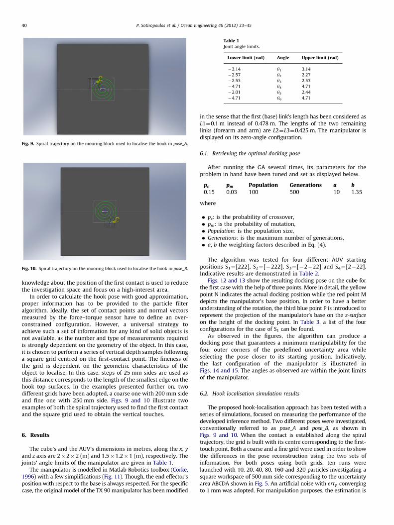
Fig. 9. Spiral trajectory on the mooring block used to localise the hook in pose_A.
Fig. 10. Spiral trajectory on the mooring block used to localise the hook in pose_B.
Table 1Joint angle limits.
Lower limit (rad) Angle Upper limit (rad)
�3.14 y1 3.14
�2.57 y2 2.27
�2.53 y3 2.53
�4.71 y4 4.71
�2.01 y5 2.44
�4.71 y6 4.71
P. Sotiropoulos et al. / Ocean Engineering 46 (2012) 33–4540
knowledge about the position of the first contact is used to reducethe investigation space and focus on a high-interest area.
In order to calculate the hook pose with good approximation,proper information has to be provided to the particle filteralgorithm. Ideally, the set of contact points and normal vectorsmeasured by the force–torque sensor have to define an over-constrained configuration. However, a universal strategy toachieve such a set of information for any kind of solid objects isnot available, as the number and type of measurements requiredis strongly dependent on the geometry of the object. In this case,it is chosen to perform a series of vertical depth samples followinga square grid centred on the first-contact point. The fineness ofthe grid is dependent on the geometric characteristics of theobject to localise. In this case, steps of 25 mm sides are used asthis distance corresponds to the length of the smallest edge on thehook top surfaces. In the examples presented further on, twodifferent grids have been adopted, a coarse one with 200 mm sideand fine one with 250 mm side. Figs. 9 and 10 illustrate twoexamples of both the spiral trajectory used to find the first contactand the square grid used to obtain the vertical touches.
6. Results
The cube’s and the AUV’s dimensions in metres, along the x, y
and z axis are 2�2�2 (m) and 1.5�1.2�1 (m), respectively. Thejoints’ angle limits of the manipulator are given in Table 1.
The manipulator is modelled in Matlab Robotics toolbox (Corke,1996) with a few simplifications (Fig. 11). Though, the end effector’sposition with respect to the base is always respected. For the specificcase, the original model of the TX 90 manipulator has been modified
in the sense that the first (base) link’s length has been considered asL1¼0.1 m instead of 0.478 m. The lengths of the two remaininglinks (forearm and arm) are L2¼L3¼0.425 m. The manipulator isdisplayed on its zero-angle configuration.
6.1. Retrieving the optimal docking pose
After running the GA several times, its parameters for theproblem in hand have been tuned and set as displayed below.
pc
pm Population Generations a b 0.15 0.03 100 500 10 1.35where
�
pc: is the probability of crossover, � pm: is the probability of mutation, � Population: is the population size, � Generations: is the maximum number of generations, � a, b the weighting factors described in Eq. (4).The algorithm was tested for four different AUV startingpositions S1¼[222], S2¼[�222], S3¼[�2�22] and S4¼[2�22].Indicative results are demonstrated in Table 2.
Figs. 12 and 13 show the resulting docking pose on the cube forthe first case with the help of three points. More in detail, the yellowpoint N indicates the actual docking position while the red point Mdepicts the manipulator’s base position. In order to have a betterunderstanding of the rotation, the third blue point P is introduced torepresent the projection of the manipulator’s base on the z-surface
on the height of the docking point. In Table 3, a list of the fourconfigurations for the case of S1 can be found.
As observed in the figures, the algorithm can produce adocking pose that guarantees a minimum manipulability for thefour outer corners of the predefined uncertainty area whileselecting the pose closer to its starting position. Indicatively,the last configuration of the manipulator is illustrated inFigs. 14 and 15. The angles as observed are within the joint limitsof the manipulator.
6.2. Hook localisation simulation results
The proposed hook-localisation approach has been tested with aseries of simulations, focused on measuring the performance of thedeveloped inference method. Two different poses were investigated,conventionally referred to as pose_A and pose_B, as shown inFigs. 9 and 10. When the contact is established along the spiraltrajectory, the grid is built with its centre corresponding to the first-touch point. Both a coarse and a fine grid were used in order to showthe differences in the pose reconstruction using the two sets ofinformation. For both poses using both grids, ten runs werelaunched with 10, 20, 40, 80, 160 and 320 particles investigating asquare workspace of 500 mm side corresponding to the uncertaintyarea ABCDA shown in Fig. 5. An artificial noise with errp convergingto 1 mm was adopted. For manipulation purposes, the estimation is

Table 2GA test results.
fobj x (m) y (m) z (m) c (rad) w
S1 �1.4269 0.3033 0.3820 0.2500 �2.4228 0.1888
S2 �1.5857 �0.3806 0.2507 0.2452 �0.9209 0.1773
S3 �1.4404 �0.3218 �0.3669 0.2476 0.7483 0.1873
S4 �1.7274 0.3218 �0.2705 0.2310 2.2694 0.1670
Fig. 12. Final docking pose starting from S1.
Fig. 11. Zero-angle configuration.
P. Sotiropoulos et al. / Ocean Engineering 46 (2012) 33–45 41
considered correct with a translation error smaller than 5 mm and arotation error smaller than 5 degrees. Figs. 16–19 illustrate thetranslation error for both the studied poses using the two differentgrids, and with respect to the number of particles. For each run,error and standard deviation are plotted. For both pose_A and pose_B,illustrated in Figs. 9 and 10, the PF is able to converge to a solutionwithin the allowed error when the fine grid is adopted.
Figs. 20–23 present the translation and rotation error for boththe poses and adopted grids. The graphs show how the PFbehaves well when the number of particles is higher than 80,but is affected by local-minima problems with less than 80particles, regardless of the number of contact points usedas input.
The algorithm tested in these examples proved to be effectivein localising the hook when processing data obtained from thefine grid. Local minima represent the main source of errors. The
minimum number of particles required to make the error con-verge below the manipulability limit is significantly low.
7. Conclusions
In this work, an overview on the subtasks involved in themooring operations during the DIFIS dome deployment has beenprovided, namely navigation and on-site localisation, robot dock-ing and hook localisation. State-of-the-art techniques to accom-plish each subtask have been summarised and discussed. Theresearch results presented in this paper focus on robot dockingand hook localisation. The considered underwater scenario con-sists of an I-AUV attempting to dock on a mooring cube and thenlocalise a latched hook lying on an uncertainty area on the topsurface. A new approach to calculate the best docking position in

Table 3Manipulator’s configurations for S1.
S1 q1 q2 q3 q4 q5 q6
Point A (�0.25, �0.25,0) 0.204 �0.548 0.241 1.147e�16 1.878 2.219
Point B (�0.25, 0.25, 0) �0.397 �1.224 1.341 3.142 �1.454 �0.322
Point C (0.25,0.25, 0) 0.827 �2.321 2.229 3.142 �1.663 �1.546
Point D (0.25, �0.25, 0) 0.847 0.049 �1.109 7.921e�16 2.031 1.576
Fig. 13. Top view of the docking pose for S1.
Fig. 14. Manipulator’s configuration to reach point D.
Fig. 15. Top view of the manipulator.
P. Sotiropoulos et al. / Ocean Engineering 46 (2012) 33–4542

Fig. 16. Pose_A—coarse grid.
Fig. 17. Pose_A—fine grid.
Fig. 18. Pose_B—coarse grid.
Fig. 19. Pose_B—fine grid.
Fig. 20. Pose_A—coarse grid.
Fig. 21. Pose_A—fine grid.
P. Sotiropoulos et al. / Ocean Engineering 46 (2012) 33–45 43
order to guarantee high dexterity over the target area has beenintroduced, together with a hook-localisation technique using aforce–torque sensor.
A GA was adopted to calculate a near-optimal docking pose,assuring a minimum of dexterity for a manipulator’s end effectorwhile reaching the four outer edges of the search area. The

Fig. 22. Pose_B—coarse grid.
Fig. 23. Pose_B—fine grid.
P. Sotiropoulos et al. / Ocean Engineering 46 (2012) 33–4544
distance of the vehicle’s initial pose was also taken into account.The results from four different starting points were presented andit can be observed that a final docking pose closer to the startingpoint was always selected.
To localise the hook, an inference method based on Bayesianestimation has been proposed. To establish the first contact withthe object, the chosen strategy was to follow a spiral trajectory ona plane parallel to the cube top surface. Once the object isdetected, the position of the hook is inferred by taking depthsamples following a square grid over the first-touch location. Theproposed algorithm was tested with a series of simulations andproved to localise the hook when sensing over a fine grid.
The overall method could be embedded in the vehicle’s controlsystem and perform the described task in an autonomous wayenabling the use of I-AUVs for the mission in hand. Though seatrials have yet to be performed, this seems to be a ratherpromising method. Further developments towards autonomousprocedures for the remaining stages of the DIFIS deploymentprocedures would make the use of I-AUVs a feasible reality,reducing the deployment cost substantially, shortening the inter-vention time and making the overall DIFIS method even moreflexible and appealing.
Acknowledgements
This work was sponsored by the FREESUBNET project, Contractnumber MTRN-CT-2006–036186.
References
Andritsos, F., et al., 2007. Recuperation of oil trapped in ship-wrecks: the DIFISconcept. In: Proceedings of the International Symposium on Maritime Safety,Security and Environmental Protection (SSE 07), Athens.
Andritsos, F., et al., 2008. Avoidance of wreck polution. PSDMH J., 407.Aspragathos, N.A., 1996. Optimal location of path following tasks in the workspace
of a manipulator using genetic algorithms. In: Proceedings of the ARK’96.Kluwer Academic Publishers, Portroz, Slovenia.
Aspragathos, N.A., Foussias, S., 2002. Optimal location of a robot path whenconsidering velocity performance. Robotica 20 (02), 139–147.
Bingham, B., et al., 2006. Integrating precision relative positioning into JASON/MEDEA ROV operations. Mar. Technol. Soc. J. 40 (1), 87–96.
Chhatpar, S.R., Branicky, M.S., 2001. Search strategies for peg-in-hole assemblieswith position uncertainty. In: Proceedings of the 2001 IEEE/RSJ InternationalConference on Intelligent Robots and Systems..
Corke, P.I., 1996. A robotics toolbox for MATLAB. IEEE Robotics Autom. Mag. 3 (1),24–32.
Cozijn, H., et al., 2008. DIFIS—double inverted funnel for the intervention on shipwrecks. In: Proceedings of the International Oil Spill Conference (IOSC 2008),Savannah, Georgia, USA.
DIFIS, 2005. DIFIS Project Web Site. Available from: //http://www.ifremer.fr/difis/S.Dubey, R., Luh, J.Y.S., 1988. Redundant robot control using task based performance
measures. J. Robotic Syst. 5 (5), 409–432.Evans, J., et al., 2003. Autonomous docking for Intervention-AUVs using sonar and
video-based real-time 3D pose estimation. In: Proceedings of the OCEANS 2003.Fox, D., et al., 1999. Monte Carlo localization: efficient position estimation for
mobile robots. In: Proceedings of the National Conference on ArtificialIntelligence, pp. 343–349.
Gadeyne, K., et al., 2005. Bayesian hybrid model-state estimation applied tosimultaneous contact formation detection and geometrical parameter estima-tion. Int. J. Robotics Res. 24, 615–630.
Gadeyne, K., Bruyninckx, H., 2001. Markov techniques for object localization withforce-controlled robots. In: Proceedings of the Tenth International Conferenceon Advanced Robotics.
Grimson, W.E.L., Lozano-Perez, T., 1984. Model-based recognition and localizationfrom sparse range or tactile data. Int. J. Robotics Res. 3 (3), 3–35.
Grosset, D., et al., 2002. Quasi-rigid docking of AUV for underwater manipulations.In: Proceedings of International Workshop on Computer Science and Informa-tion Technologies, CSIT, Patras, Greece.
Konstantinopoulos, P., Andritsos, F., 2008. DIFIS —Greek innovation for theavoidance of wreck polution. Naval J. 168, 566. (Hellenic Navy).
Krupinski, S., et al., 2008. Investigation of autonomous docking strategies for roboticoperation on intervention panels. In: Proceedings of the OCEANS 2008.
Lee, P. M. et al., 2003. Visual servoing for underwater docking of an autonomousunderwater vehicle with one camera. In: Proceedings of the Oceans Con-ference Record (IEEE), vol. 2, pp. 677-682.
Marani, G., et al., 2009. Underwater autonomous manipulation for interventionmissions AUVs. Ocean Eng. 36 (1), 15–23.
Maskell, S., Gordon, N., 2001. A tutorial on particle filters for on-line nonlinear/non-Gaussian Bayesian tracking. Target Tracking: Algorithms and Applications(Ref. no. 2001/174), IEE.
Miller, P.A., et al., 2010. Autonomous underwater vehicle navigation. IEEE J.Oceanic Eng. 35 (3), 663–678.
Mitsi, S., et al., 2008. Determination of optimum robot base location consideringdiscrete end-effector positions by means of hybrid genetic algorithm. RoboticsComput.Integrated Manuf. 24 (1), 50–59.
Murray, R., et al., 1994. A Mathematical Introduction to Robotic Manipulation.CRC.
Negre, A. et al., 2008. Robust vision-based underwater target identification andhoming using self-similar landmarks. Springer Tracts in Advanced Robotics,vol. 42, pp. 51–60.
Palmer, T. et al., 2009. Vision based localization system for AUV docking on subseaintervention panels. OCEANS ’09 IEEE. Bremen, Germany.
Perry Slings by Systems, 2010. Perry Slings by Systems. Available from: //http://www. perryslingsbysystems.com.S.
Petrovskaya, Anna, et al., 2007. Touch based perception for object manipulation.In: Proceedings of the Robot Manipulation Workshop.
Salisbury, J.K., Craig, J.J., 1982. Articulated hands. Int. J. Robotics Res. 1 (1), 4–17.Scherbatyuk, A.P., 1995. The AUV positioning using ranges from one transponder
LBL. In: OCEANS’95 MTS/IEEE: Challenges of our Changing Global Environ-ment, Conference Proceedings.
Sotiropoulos, P., et al., 2010. Determination of the optimum docking position of anunderwater unmanned vehicle using a genetic algorithm. In: Proceedings ofthe ICIAR’10, San Francisco.
Stokey, R. et al., 1997. Docking system for REMUS, an autonomous underwatervehicle. In: Proceedings of the Oceans Conference Record (IEEE), vol. 2, pp.1132–1136.

P. Sotiropoulos et al. / Ocean Engineering 46 (2012) 33–45 45
Thrun, S., et al., 2005. Probabilistic Robotics (Intelligent Robotics and AutonomousAgents). The MIT Press.
Tian, L., Collins, C., 2005. Optimal placement of a two-link planar manipulatorusing a genetic algorithm. Robotica 23 (2), 169–176.
Weiss, P. et al., 2009. FreeSUB: Dynamic stabilization and docking for autonomousUnderwater vehicles. In: Proceedings of the 13th International Symposium onUnmanned Untethered Submersible Technology(UUST), Durham, USA.
Woods, A., et al., 1994. Experiences of using stereoscopic video with an under-water remotely operated vehicle. Underwater Intervention. San Diego, Cali-fornia, pp. 34–38.
Yashima, M., Yamawaki, T., 2009. Task-oriented accuracy measure for dexterousmanipulation. In: Proceedings of the IEEE International Conference onRobotics and Biomimetics, ROBIO 2008.
Yoshikawa, T., 1990. Foundations of Robotics. The MIT Press, Cambridge Massachusetts.