Embed Size (px)
Citation preview
Optimal design of spiral-wound membranenetworks for gas separations
Runhong Qi, Michael A. Henson*
Department of Chemical Engineering, Louisiana State University, Baton Rouge, LA 70803-7303, USA
Received 13 January 1998; received in revised form 15 May 1998; accepted 22 May 1998
Abstract
An optimal design strategy for spiral-wound membrane networks based on an approximate permeator model and a mixed-
integer nonlinear programming (MINLP) solution strategy is proposed. A general permeator system superstructure is used to
embed a very large number of possible network con®gurations. The superstructure allows the development of a MINLP design
strategy which simultaneously optimizes the permeator con®guration and operating conditions to minimize an objective
function which approximates the total annual process cost. Case studies for the separation of CO2/CH4 mixtures in natural gas
treatment and enhanced oil recovery are presented. Permeator con®gurations are derived for different number of separation
stages for both continuous and discrete membrane areas. The proposed approach provides an ef®cient methodology for the
preliminary design of multi-stage membrane separation systems for binary gas mixtures. # 1998 Elsevier Science B.V. All
rights reserved.
Keywords: Gas separations; Modules; Design; Optimization
1. Introduction
Membrane systems have become viable alternatives
to conventional gas separation technologies such as
pressure swing adsorption and cryogenic distillation.
A particularly important application of membrane
technology is the use of spiral-wound permeators to
separate methane/carbon dioxide mixtures encoun-
tered in natural gas treatment and enhanced oil recov-
ery. The economics of membrane separation processes
depend critically on the process design. Single-stage
systems have low capital costs, but they are appro-
priate only for moderate product purity and recovery
requirements. Multiple separation stages and recycle
are required for more demanding applications. The
design of a membrane system involves the determina-
tion of: (i) the con®guration of the permeator network;
and (ii) the operating conditions of the individual
permeators.
Membrane systems currently are designed via a
sequential procedure in which the permeator con®g-
uration is chosen by process heuristics and the oper-
ating conditions are determined using some type of
optimization procedure. Many investigators have con-
sidered the design of multi-stage gas permeation
systems [1±14]. Spillman et al. [4] design membrane
systems to separate CO2/CH4 mixtures encountered in
natural gas treatment and enhanced oil recovery.
Several permeator con®gurations are optimized for
Journal of Membrane Science 148 (1998) 71±89
*Corresponding author. Tel.: +1-504-388-3690; fax: +1-504-
388-1476; e-mail: [email protected]
0376-7388/98/$ ± see front matter # 1998 Elsevier Science B.V. All rights reserved.
P I I : S 0 3 7 6 - 7 3 8 8 ( 9 8 ) 0 0 1 4 3 - 4
a particular feed composition. Babcock et al. [5]
evaluate the economics of single-stage and three-stage
membrane systems for the natural gas treatment by
providing comparisons with amine treatment pro-
cesses. Bhide and Stern present detailed case studies
of membrane separation systems for natural gas treat-
ment [6,7] and oxygen enrichment of air [8,9]. A grid
search method is used to optimize the operating con-
ditions for several different con®gurations. Agrawal
and Xu [11±14] develop a stepwise procedure for the
synthesis of membrane cascades using limited num-
bers of recycle compressors. This approach is based on
a master cascade which contains a large number of
possible permeation stages and a speci®ed number of
recycle compressors. Substructure cascades are gen-
erated by eliminating unwanted recycle compressors
and membrane stages using heuristic process analysis.
A systematic method for optimizing the membrane
cascades and their operating conditions is not pre-
sented.
Sequential design procedures are very inef®cient
because it is usually not feasible to enumerate and
evaluate all possible network con®gurations. As a
result, existing design techniques often yield subopti-
mal ¯owsheets. During the last decade, a wide variety
of process design and synthesis problems have been
solved by mathematical programming [15±17]. This
approach utilizes rigorous optimization methods to
systematically determine the process con®guration
and operating conditions. A popular approach is to
postulate a superstructure which embeds many pro-
cess con®gurations, each of which is a candidate for
the optimal process ¯owsheet [18]. The superstructure
is mathematically described by a model which con-
tains both continuous and integer variables that repre-
sent operating conditions, as well as processing units
and their interconnections. The mixed-integer non-
linear programming (MINLP) model is posed as a set
of constraints in an optimization problem in which the
total annual process cost usually is the objective
function. An algorithm for solving the resulting
MINLP problem has been developed and implemen-
ted as DICOPT�� [19] within the general algebraic
modeling system (GAMS) [20]. MINLP techniques
have allowed extensive progress in the synthesis of
heat-exchanger networks, distillation column
sequences, reactor networks, and mass-exchange net-
works [15±18].
For gas membrane separation systems, a major
dif®culty in applying MINLP synthesis techniques
is that fundamental permeator models are comprised
of differential-algebraic-integral equations with
mixed boundary conditions. These models are too
mathematically complex and computationally inten-
sive to be utilized for MINLP design. An alternative
approach is to develop approximate models which
provide a more reasonable compromise between pre-
diction accuracy and computational ef®ciency.
Approximate models usually consist of a set of non-
linear algebraic equations which can be solved much
more ef®ciently. Petterson and Lien [10] study the
design of single-stage and multi-stage membrane
systems using an algebraic model for hollow-®ber
gas permeators. The permeator con®gurations are
chosen a priori, and nonlinear programming (NLP)
is used to optimize the operating conditions. However,
the approximate permeator model does not yield
accurate predictions when the feed concentration of
the more permeable component is higher than 0.3±
0.5 mol fraction. Recently, we proposed an approx-
imate modeling technique for spiral-wound permea-
tors separating binary [21] and multicomponent [22]
gas mixtures. The model development is based on
simplifying basic transport models which include
permeate-side pressure drop. The resulting models
are ideally suited for process design because the
nonlinear algebraic equations can be solved very
ef®ciently and yield excellent prediction accuracy
over a wide range of operating conditions. We have
used the approximate binary model to develop a NLP
design strategy that allows systematic determination
of the operating conditions for a speci®ed permeator
con®guration [23].
In this paper, we utilize the same binary model to
develop a process synthesis strategy for spiral-wound
membrane systems which allows simultaneous opti-
mization of the permeator network and operating
conditions. The approach is based on a permeator
system superstructure which ef®ciently embeds a very
large number of possible network con®gurations. The
superstructure is used to develop a MINLP design
strategy which determines the membrane system that
minimizes the approximate annual process cost. The
methodology is applied to the separation of CO2/CH4
mixtures in natural gas treatment and enhanced oil
recovery. Optimal separation systems are derived for
72 R. Qi, M.A. Henson / Journal of Membrane Science 148 (1998) 71±89
different number of separation stages with both con-
tinuous and discrete membrane areas.
2. Problem statement
The problem of designing spiral-wound membrane
systems for gas separations can be described as: given
a feed mixture of known conditions, synthesize the
minimum cost network of spiral-wound permeators
and recycle compressors that separates the feed stream
into products of speci®ed compositions. The mem-
brane properties and cost related parameters are
assumed to be known.
The design task involves the determination of the
optimal system con®guration, as well as speci®cation
of the process unit sizes and operating conditions. As a
®rst step, it is necessary to utilize a permeator model
that is suf®ciently accurate to predict the separation
performance and computationally ef®cient for math-
ematical programming. The next step is to derive a
permeator system superstructure which embeds all
system con®gurations of practical interest, formulate
the superstructure as a MINLP model, and develop a
suitable solution strategy. To facilitate the subsequent
development, the following assumptions are invoked:
1. The feed stream contains a binary gas mixture at a
relatively high pressure.
2. The feed-side pressure for each stage is equal to the
pressure of the feed stream.
3. The feed-side pressure drop is negligible for each
stage.
4. There is no pressure drop between permeation
stages.
5. The permeate stream pressures between stages are
design variables, while the product permeate
stream pressure is pre-determined.
6. All permeators and compressors operate at isother-
mal conditions.
3. Spiral-wound permeator model
The proposed optimal design strategy requires an
accurate, yet computationally ef®cient, model of a
spiral-wound gas permeator. In this section, we
describe an approximate model which is derived
directly from a fundamental cross-¯ow model [24]
by assuming that the residual ¯ow rate is constant in
the direction of permeate ¯ow. The approximate cross-
¯ow model is suf®ciently accurate for spiral-wound
permeators. A more detailed discussion of the model is
given elsewhere [21].
The approximate model is comprised of four non-
linear algebraic equations. Eq. (1) describes the
permeate-side pressure distribution,
2 � 20 �
1
2C 1ÿ �r� � 1ÿ h2
ÿ �(1)
where is the ratio of the permeate-side and feed-side
pressures, 0, is at the permeate outlet, �r, the
dimensionless residue gas ¯ow rate and h, the dimen-
sionless membrane leaf-length variable, and:
C � 2RgT�LUf
WdmBP2(2)
The remaining variables are de®ned in Section 7. The
coef®cient C can be factored as follows:
C � C00Uf
AP2(3)
where Uf is the feed gas ¯ow rate, P, the feed-side
pressure, A, the membrane area, and C00, a parameter
that depends on the internal properties of the permea-
tor. The second equation describes the effect of and
the local permeate-side concentration y0 on the dimen-
sionless feed-side ¯ow rate �,
�� ; y0� � y0
y0f
� �a1ÿ y0
1ÿ y0f
� �b �ÿ ��ÿ 1�y0�ÿ ��ÿ 1�y0f
� �(4)
where y0f is y0 at the feed inlet, �, the membrane
selectivity, and:
a � ��ÿ 1� � 1
��ÿ 1��1ÿ � b � ��ÿ 1� ÿ ���ÿ 1��1ÿ � (5)
The dimensionless feed-side ¯ow rate at the residue
outlet can be written as,
�r � �� ; y0r� (6)
where y0r is y0 at the residue outlet.
The third equation describes the relation between
the dimensionless permeation factor,
R � 2WLQ2P
dUf
� AQ2
d
P
Uf
(7)
R. Qi, M.A. Henson / Journal of Membrane Science 148 (1998) 71±89 73
and the local permeate concentration along the residue
outlet y0r:
R � 1
��1ÿ ���ÿ ��ÿ 1�y0f
ÿ ��ÿ ��ÿ 1�y0r��� ; y0r� ÿ ��ÿ 1�I� ; y0r�g (8)
Here I� ; y0r� is an integral function which is approxi-
mated using Gaussian quadrature [25],
I� ; y0r� � �y0r ÿ y0f�XMj�1
�� ; y0j�wj (9)
where M is the number of quadrature points, wj,
the quadrature weight at the quadrature point �j,
and:
y0j � y0f � �j�y0r ÿ y0f� (10)
The fourth equation describes the relation between
the local feed-side concentration x and the local
permeate-side concentration y0:
y0
1ÿ y0� ��xÿ y0�
1ÿ xÿ �1ÿ y0� (11)
Simultaneous solution of Eqs. (1), (6), (8) and (11)
with x�xf at the quadrature point hi (see below) yields
(hi), �r(hi), yr0(hi), and yf
0(hi). The local residue
concentration xr(hi) is obtained from Eq. (11) with
y0�yr0(hi).
The ¯ow rate and concentration of the ef¯uent
permeate stream are calculated from the integral
expressions that are approximated using the Gaussian
quadrature. Under most conditions, a single quadra-
ture point at h1�0.5 is suf®cient. In this case, the
resulting equations are [21]:
�0 � 1ÿ �r�h1� (12)
y0 � xf ÿ xr�h1��r�h1�1ÿ �r�h1� (13)
The ¯ow rate and concentration of the ef¯uent residue
stream are determined from an overall material bal-
ance about the permeator. We have shown that the
approximate model compares favorably with the fun-
damental model in terms of prediction accuracy [21].
The major advantage of the approximate model is that
the nonlinear algebraic equations can be solved 200±
400 times faster than the fundamental differential-
algebraic-integral equations using the shooting
method [24].
4. Optimal design strategy
4.1. Permeator superstructure
The superstructure approach to process design pro-
vides a systematic framework for simultaneous opti-
mization of process con®guration and operating
conditions [18]. Superstructures have been developed
for a number of membrane separation systems, includ-
ing reverse osmosis [26] and pervaporation [27] net-
works. For gas membrane separation systems, the
basic components of the superstructure are permea-
tors, compressors, stream mixers, and stream splitters.
An ideal superstructure is suf®ciently `rich' to repre-
sent all process con®gurations of practical interest, yet
suf®ciently `simple' to eliminate all unreasonable
con®gurations.
The permeator system superstructure is derived as
described below [18]. Note that each separation stage
may be comprised of several permeators in parallel or
in series.
1. The feed stream is split into individual feed
streams for each permeation stage.
2. The inlet stream to a particular stage consists of: its
individual feed stream; recycle streams obtained
from the permeator's effluent streams; and recycle
streams obtained from the effluent streams of all
other stages.
3. For each stage, the permeate and residue streams
are split into: recycle streams for the particular
stage; recycle streams for all other stages; and
streams that are sent to the final product mixers.
The permeate recycle streams must be compressed
to the feed pressure before being sent to the feed
stream mixers.
4. The inlet streams for the final permeate (residue)
mixer are obtained from the permeate (residue)
streams of all stages.
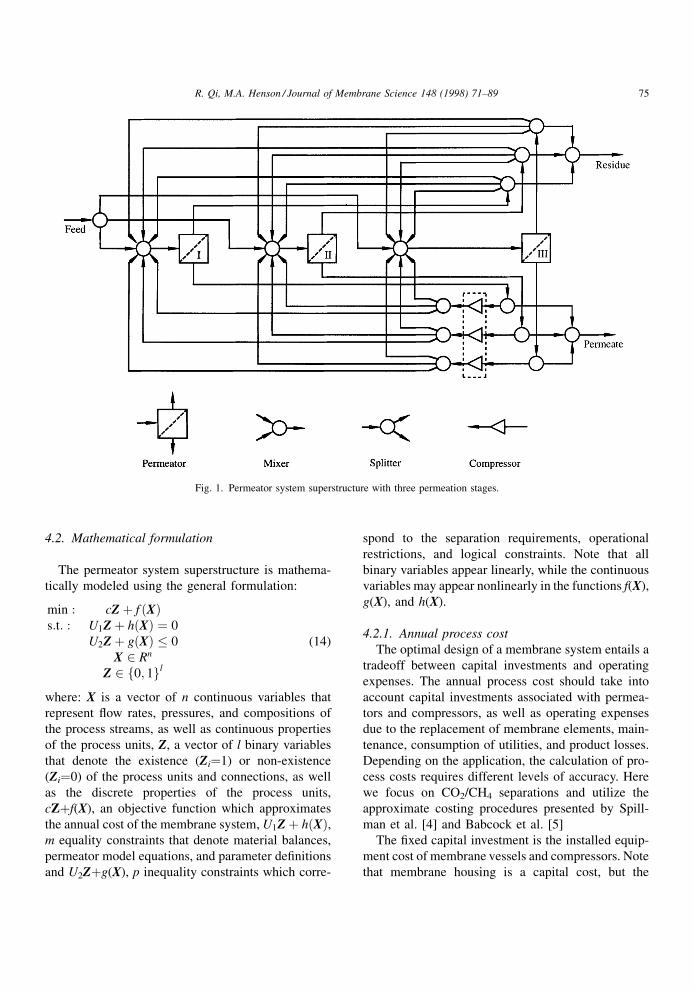
As an illustration, the system superstructure for
three separation stages is shown in Fig. 1. This super-
structure is capable of representing a very large num-
ber of permeator con®gurations with three separation
stages. Superstructures containing different number of
separation stages are developed similarly.
74 R. Qi, M.A. Henson / Journal of Membrane Science 148 (1998) 71±89
4.2. Mathematical formulation
The permeator system superstructure is mathema-
tically modeled using the general formulation:
min : cZ� f �X�s:t: : U1Z� h�X� � 0
U2Z� g�X� � 0
X 2 Rn
Z 2 f0; 1gl
(14)
where: X is a vector of n continuous variables that
represent ¯ow rates, pressures, and compositions of
the process streams, as well as continuous properties
of the process units, Z, a vector of l binary variables
that denote the existence (Zi�1) or non-existence
(Zi�0) of the process units and connections, as well
as the discrete properties of the process units,
cZ�f(X), an objective function which approximates
the annual cost of the membrane system, U1Z� h�X�,m equality constraints that denote material balances,
permeator model equations, and parameter de®nitions
and U2Z�g(X), p inequality constraints which corre-
spond to the separation requirements, operational
restrictions, and logical constraints. Note that all
binary variables appear linearly, while the continuous
variables may appear nonlinearly in the functions f(X),
g(X), and h(X).
4.2.1. Annual process cost
The optimal design of a membrane system entails a
tradeoff between capital investments and operating
expenses. The annual process cost should take into
account capital investments associated with permea-
tors and compressors, as well as operating expenses
due to the replacement of membrane elements, main-
tenance, consumption of utilities, and product losses.
Depending on the application, the calculation of pro-
cess costs requires different levels of accuracy. Here
we focus on CO2/CH4 separations and utilize the
approximate costing procedures presented by Spill-
man et al. [4] and Babcock et al. [5]
The ®xed capital investment is the installed equip-
ment cost of membrane vessels and compressors. Note
that membrane housing is a capital cost, but the
Fig. 1. Permeator system superstructure with three permeation stages.
R. Qi, M.A. Henson / Journal of Membrane Science 148 (1998) 71±89 75
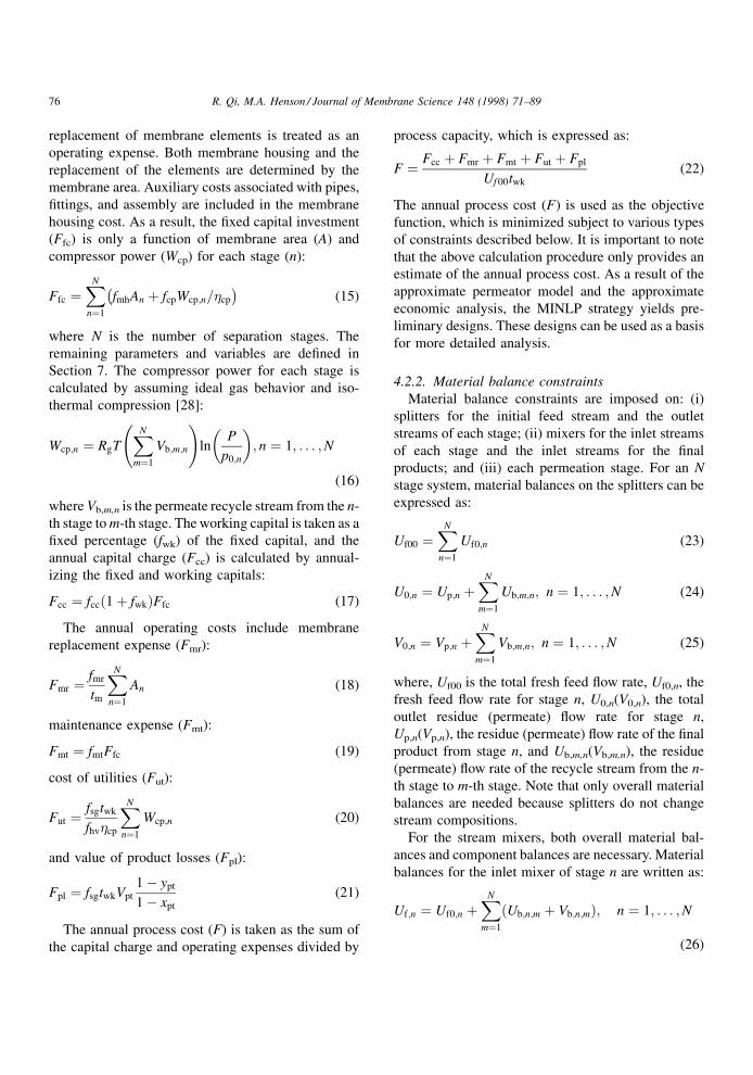
replacement of membrane elements is treated as an
operating expense. Both membrane housing and the
replacement of the elements are determined by the
membrane area. Auxiliary costs associated with pipes,
®ttings, and assembly are included in the membrane
housing cost. As a result, the ®xed capital investment
(Ffc) is only a function of membrane area (A) and
compressor power (Wcp) for each stage (n):
Ffc �XN
n�1
fmhAn � fcpWcp;n=�cp
ÿ �(15)
where N is the number of separation stages. The
remaining parameters and variables are de®ned in
Section 7. The compressor power for each stage is
calculated by assuming ideal gas behavior and iso-
thermal compression [28]:
Wcp;n � RgTXN
m�1
Vb;m;n
!ln
P
p0;n
� �; n � 1; . . . ;N
(16)
where Vb,m,n is the permeate recycle stream from the n-
th stage to m-th stage. The working capital is taken as a
®xed percentage (fwk) of the ®xed capital, and the
annual capital charge (Fcc) is calculated by annual-
izing the ®xed and working capitals:
Fcc � fcc�1� fwk�Ffc (17)
The annual operating costs include membrane
replacement expense (Fmr):
Fmr � fmr
tm
XN
n�1
An (18)
maintenance expense (Fmt):
Fmt � fmtFfc (19)
cost of utilities (Fut):
Fut � fsgtwk
fhv�cp
XN
n�1
Wcp;n (20)
and value of product losses (Fpl):
Fpl � fsgtwkVpt
1ÿ ypt
1ÿ xpt
(21)
The annual process cost (F) is taken as the sum of
the capital charge and operating expenses divided by
process capacity, which is expressed as:
F � Fcc � Fmr � Fmt � Fut � Fpl
Uf 00twk(22)
The annual process cost (F) is used as the objective
function, which is minimized subject to various types
of constraints described below. It is important to note
that the above calculation procedure only provides an
estimate of the annual process cost. As a result of the
approximate permeator model and the approximate
economic analysis, the MINLP strategy yields pre-
liminary designs. These designs can be used as a basis
for more detailed analysis.
4.2.2. Material balance constraints
Material balance constraints are imposed on: (i)
splitters for the initial feed stream and the outlet
streams of each stage; (ii) mixers for the inlet streams
of each stage and the inlet streams for the ®nal
products; and (iii) each permeation stage. For an N
stage system, material balances on the splitters can be
expressed as:
Uf00 �XN
n�1
Uf0;n (23)
U0;n � Up;n �XN
m�1
Ub;m;n; n � 1; . . . ;N (24)
V0;n � Vp;n �XN
m�1
Vb;m;n; n � 1; . . . ;N (25)
where, Uf00 is the total fresh feed ¯ow rate, Uf0,n, the
fresh feed ¯ow rate for stage n, U0,n(V0,n), the total
outlet residue (permeate) ¯ow rate for stage n,
Up,n(Vp,n), the residue (permeate) ¯ow rate of the ®nal
product from stage n, and Ub,m,n(Vb,m,n), the residue
(permeate) ¯ow rate of the recycle stream from the n-
th stage to m-th stage. Note that only overall material
balances are needed because splitters do not change
stream compositions.
For the stream mixers, both overall material bal-
ances and component balances are necessary. Material
balances for the inlet mixer of stage n are written as:
Uf;n � Uf0;n �XN
m�1
�Ub;n;m � Vb;n;m�; n � 1; . . . ;N
(26)
76 R. Qi, M.A. Henson / Journal of Membrane Science 148 (1998) 71±89
Uf;nxf;n � Uf0;nxf0 �XN
m�1
�Ub;n;mx0;m � Vb;n;my0;m�;
n � 1; . . . ;N (27)
Note that the recycle streams are taken from the m-th
stage and terminate at the n-th stage. Material balances
for the product mixers are expressed as:
Upt �XN
n�1
Up;n (28)
Uptxpt �XN
n�1
Up;nx0;n (29)
Vpt �XN
n�1
Vp;n (30)
Vptypt �XN
n�1
Vp;ny0;n (31)
where, Upt and xpt are the total ¯ow rate and concen-
tration of the ®nal residue product, and Vpt and ypt are
the total ¯ow rate and concentration of the ®nal
permeate product. Material balances about each per-
meation stage yield:
Uf;n � U0;n � V0;n; n � 1; . . . ;N (32)
Uf;nxf ;n � U0;nx0;n � V0;ny0;n; n � 1; . . . ;N (33)
4.2.3. Permeator model constraints
The permeator model constraints are the approx-
imate permeator model equations written for each
stage. Some of the equations are manipulated to
facilitate computer implementation. The resulting
model equations are presented in the Appendix A.
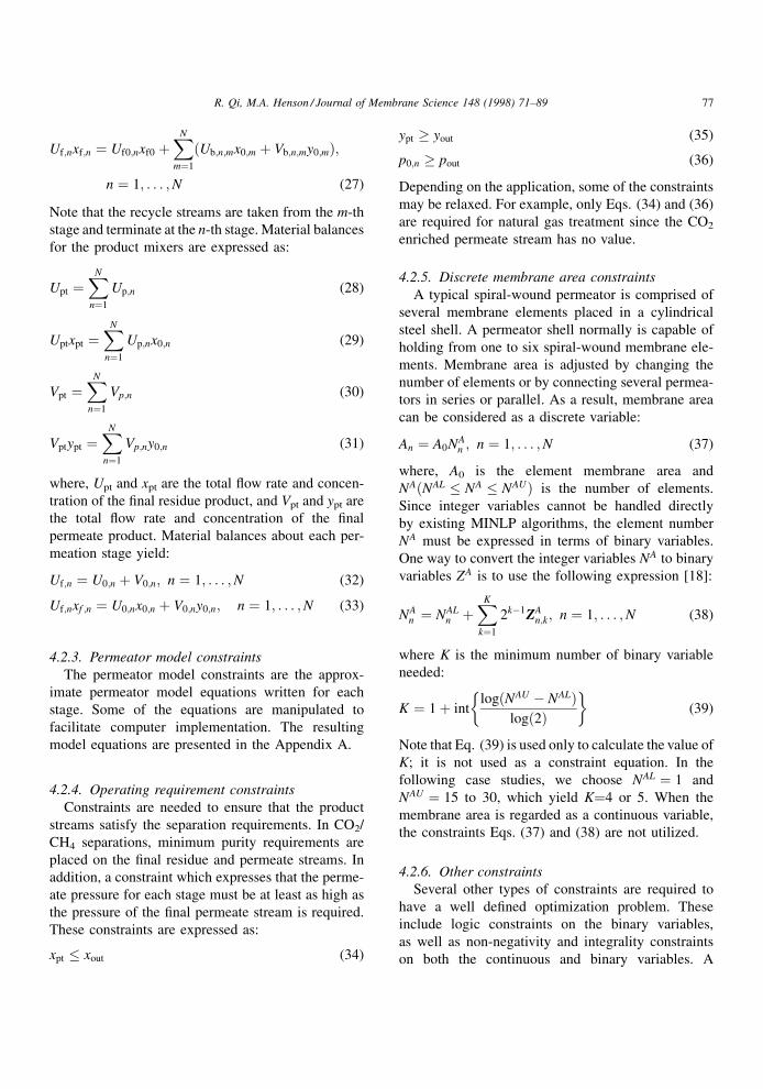
4.2.4. Operating requirement constraints
Constraints are needed to ensure that the product
streams satisfy the separation requirements. In CO2/
CH4 separations, minimum purity requirements are
placed on the ®nal residue and permeate streams. In
addition, a constraint which expresses that the perme-
ate pressure for each stage must be at least as high as
the pressure of the ®nal permeate stream is required.
These constraints are expressed as:
xpt � xout (34)
ypt � yout (35)
p0;n � pout (36)
Depending on the application, some of the constraints
may be relaxed. For example, only Eqs. (34) and (36)
are required for natural gas treatment since the CO2
enriched permeate stream has no value.
4.2.5. Discrete membrane area constraints
A typical spiral-wound permeator is comprised of
several membrane elements placed in a cylindrical
steel shell. A permeator shell normally is capable of
holding from one to six spiral-wound membrane ele-
ments. Membrane area is adjusted by changing the
number of elements or by connecting several permea-
tors in series or parallel. As a result, membrane area
can be considered as a discrete variable:
An � A0NAn ; n � 1; . . . ;N (37)
where, A0 is the element membrane area and
NA�NAL � NA � NAU� is the number of elements.
Since integer variables cannot be handled directly
by existing MINLP algorithms, the element number
NA must be expressed in terms of binary variables.
One way to convert the integer variables NA to binary
variables ZA is to use the following expression [18]:
NAn � NAL
n �XK
k�1
2kÿ1ZAn;k; n � 1; . . . ;N (38)
where K is the minimum number of binary variable
needed:
K � 1� intlog�NAU ÿ NAL�
log�2�� �
(39)
Note that Eq. (39) is used only to calculate the value of
K; it is not used as a constraint equation. In the
following case studies, we choose NAL � 1 and
NAU � 15 to 30, which yield K�4 or 5. When the
membrane area is regarded as a continuous variable,
the constraints Eqs. (37) and (38) are not utilized.
4.2.6. Other constraints
Several other types of constraints are required to
have a well de®ned optimization problem. These
include logic constraints on the binary variables,
as well as non-negativity and integrality constraints
on both the continuous and binary variables. A
R. Qi, M.A. Henson / Journal of Membrane Science 148 (1998) 71±89 77
description of these constraints is included in the
Appendix A.
4.3. Solution strategy
The MINLP design model is solved using the
algorithm of Viswanathan and Grossmann [19], which
is available in GAMS [20] as the solver DICOPT��.
The solution technique is based on an outer approx-
imation approach in which the MINLP problem is
decomposed into a series of NLP and MILP subpro-
blems [29]. These subproblems can be solved using
any NLP and MILP solvers that run in the GAMS
environment. In this paper, CONOPT2 is used for the
NLP problem and XA is used for the MILP problem. It
is important to note that the MINLP formulation
usually yields a nonconvex optimization problem.
As a result, the solution obtained represents a local
optimum. We address this problem by initializing the
variables at several different points, setting reasonable
bounds on variables, and adjusting the DICOPT��options to facilitate convergence to the global opti-
mum.
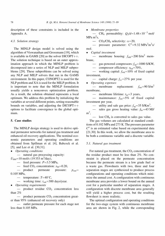
5. Case studies
The MINLP design strategy is used to derive opti-
mal permeator networks for natural gas treatment and
enhanced oil recovery applications. The nominal eco-
nomic parameters and operating conditions are
obtained from Spillman et al. [4], Babcock et al.
[5], and Lee et al. [30,31].
� Operating conditions
Ð natural gas processing capacity:
Uf00�10 mol/s (19 353 m3/day),
Ð feed pressure: P�3.5 MPa,
Ð feed CO2 concentration: xf0�0.20,
Ð product permeate pressure: pout�0.105 MPa,
Ð temperature: T�408C,
Ð working time: twk�300 days/year.
� Operating requirements
Ð product residue CO2 concentration less
than 2%
Ð product permeate CO2 concentration great-
er than 95% (enhanced oil recovery only)
Ð outlet permeate pressure for each stage not
less than 0.105 MPa.
� Membrane properties
Ð CH4 permeability: Q2/d�1.48�10ÿ3 mol/
MPa m2s,
РCO2/CH4 selectivity: ��20,
Ð pressure parameter: C00�9.32 MPa2m2s/
mol.
� Capital investment
Ð membrane housing: fmh�200 $/m2 mem-
brane,
Ð gas-powered compressors: fcp�1000 $/KW,
Ð compressor efficiency: �cp�70%,
Ð working capital: fwk�10% of fixed capital
investment,
Ð capital charge: fcc�27% per year.
� Operating expenses
Ð membrane replacement: fmr�90 $/m2
membrane,
Ð membrane lifetime: tm�3 years,
Ð maintenance: fmt�5% of fixed capital
investment per year,
Ð utility and sale gas price: fsg�35 $/Km3,
Ð sales gas gross heating value: fhv�43 MJ/
m3,
Ð lost CH4 is converted to sales gas value.
The gas volumes are calculated at standard condi-
tions of 0.102 MPa and 273 K. The pressure parameter
C00 is an estimated value based on experimental data
[21,30]. In this work, we allow the membrane area to
be both a continuous variable and a discrete variable.
5.1. Natural gas treatment
For natural gas treatment, the CO2 concentration of
the residue product must be less than 2%. No con-
straint is placed on the permeate concentration
because the permeate stream is a low grade fuel or
a waste gas. Flowsheets with two, three and four
separation stages are synthesized to produce process
con®gurations and operating conditions which mini-
mize the annual cost. A con®guration with continuous
membrane area provides a lower bound on the annual
cost for a particular number of separation stages. A
con®guration with discrete membrane area generally
will yield a higher process cost, but the resulting
¯owsheet is more realistic.
The optimal con®guration and operating conditions
for the two-stage system with continuous membrane
area are shown in Fig. 2, while the corresponding
78 R. Qi, M.A. Henson / Journal of Membrane Science 148 (1998) 71±89
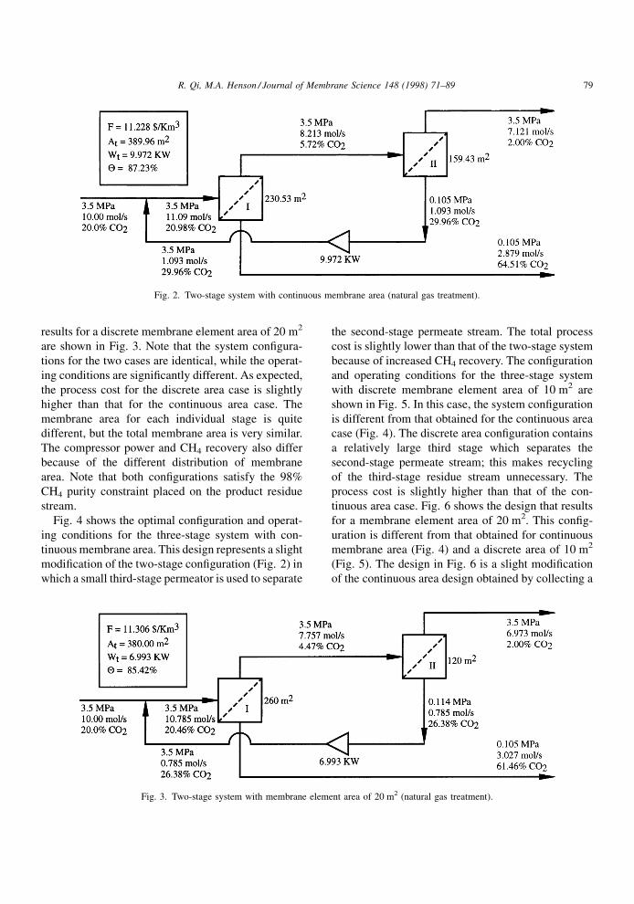
results for a discrete membrane element area of 20 m2
are shown in Fig. 3. Note that the system con®gura-
tions for the two cases are identical, while the operat-
ing conditions are signi®cantly different. As expected,
the process cost for the discrete area case is slightly
higher than that for the continuous area case. The
membrane area for each individual stage is quite
different, but the total membrane area is very similar.
The compressor power and CH4 recovery also differ
because of the different distribution of membrane
area. Note that both con®gurations satisfy the 98%
CH4 purity constraint placed on the product residue
stream.
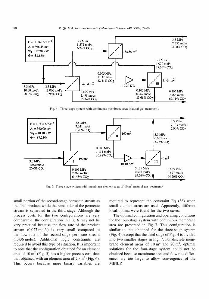
Fig. 4 shows the optimal con®guration and operat-
ing conditions for the three-stage system with con-
tinuous membrane area. This design represents a slight
modi®cation of the two-stage con®guration (Fig. 2) in
which a small third-stage permeator is used to separate
the second-stage permeate stream. The total process
cost is slightly lower than that of the two-stage system
because of increased CH4 recovery. The con®guration
and operating conditions for the three-stage system
with discrete membrane element area of 10 m2 are
shown in Fig. 5. In this case, the system con®guration
is different from that obtained for the continuous area
case (Fig. 4). The discrete area con®guration contains
a relatively large third stage which separates the
second-stage permeate stream; this makes recycling
of the third-stage residue stream unnecessary. The
process cost is slightly higher than that of the con-
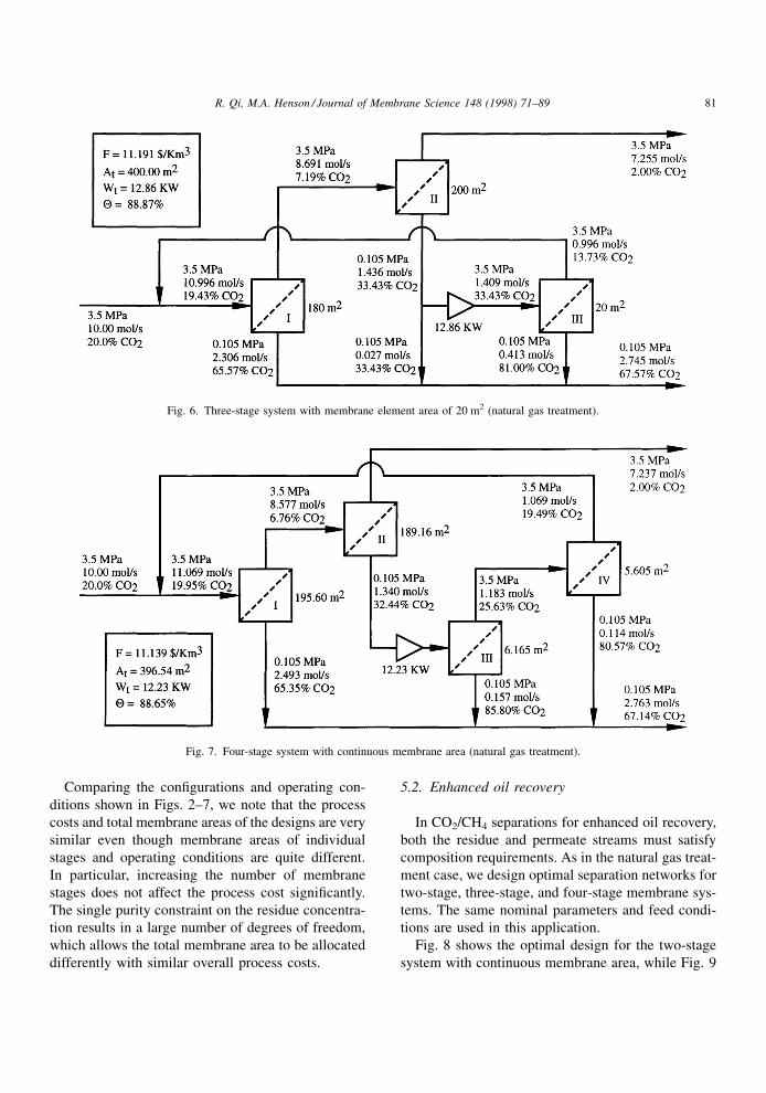
tinuous area case. Fig. 6 shows the design that results
for a membrane element area of 20 m2. This con®g-
uration is different from that obtained for continuous
membrane area (Fig. 4) and a discrete area of 10 m2
(Fig. 5). The design in Fig. 6 is a slight modi®cation
of the continuous area design obtained by collecting a
Fig. 2. Two-stage system with continuous membrane area (natural gas treatment).
Fig. 3. Two-stage system with membrane element area of 20 m2 (natural gas treatment).
R. Qi, M.A. Henson / Journal of Membrane Science 148 (1998) 71±89 79
small portion of the second-stage permeate stream as
the ®nal product, while the remainder of the permeate
stream is separated in the third stage. Although the
process costs for the two con®gurations are very
comparable, the con®guration in Fig. 6 may not be
very practical because the ¯ow rate of the product
stream (0.027 mol/s) is very small compared to
the ¯ow rate of the second-stage permeate stream
(1.436 mol/s). Additional logic constraints are
required to avoid this type of situation. It is important
to note that the con®guration obtained for an element
area of 10 m2 (Fig. 5) has a higher process cost than
that obtained with an element area of 20 m2 (Fig. 6).
This occurs because more binary variables are
required to represent the constraint Eq. (38) when
small element areas are used. Apparently, different
local optima were found for the two cases.
The optimal con®guration and operating conditions
for the four-stage system with continuous membrane
area are presented in Fig. 7. This con®guration is
similar to that obtained for the three-stage system
(Fig. 4), except that the third stage of Fig. 4 is divided
into two smaller stages in Fig. 7. For discrete mem-
brane element areas of 10 m2 and 20 m2, optimal
solutions for the four-stage system could not be
obtained because membrane area and ¯ow rate differ-
ences are too large to allow convergence of the
MINLP.
Fig. 4. Three-stage system with continuous membrane area (natural gas treatment).
Fig. 5. Three-stage system with membrane element area of 10 m2 (natural gas treatment).
80 R. Qi, M.A. Henson / Journal of Membrane Science 148 (1998) 71±89
Comparing the con®gurations and operating con-
ditions shown in Figs. 2±7, we note that the process
costs and total membrane areas of the designs are very
similar even though membrane areas of individual
stages and operating conditions are quite different.
In particular, increasing the number of membrane
stages does not affect the process cost signi®cantly.
The single purity constraint on the residue concentra-
tion results in a large number of degrees of freedom,
which allows the total membrane area to be allocated
differently with similar overall process costs.
5.2. Enhanced oil recovery
In CO2/CH4 separations for enhanced oil recovery,
both the residue and permeate streams must satisfy
composition requirements. As in the natural gas treat-
ment case, we design optimal separation networks for
two-stage, three-stage, and four-stage membrane sys-
tems. The same nominal parameters and feed condi-
tions are used in this application.
Fig. 8 shows the optimal design for the two-stage
system with continuous membrane area, while Fig. 9
Fig. 6. Three-stage system with membrane element area of 20 m2 (natural gas treatment).
Fig. 7. Four-stage system with continuous membrane area (natural gas treatment).
R. Qi, M.A. Henson / Journal of Membrane Science 148 (1998) 71±89 81
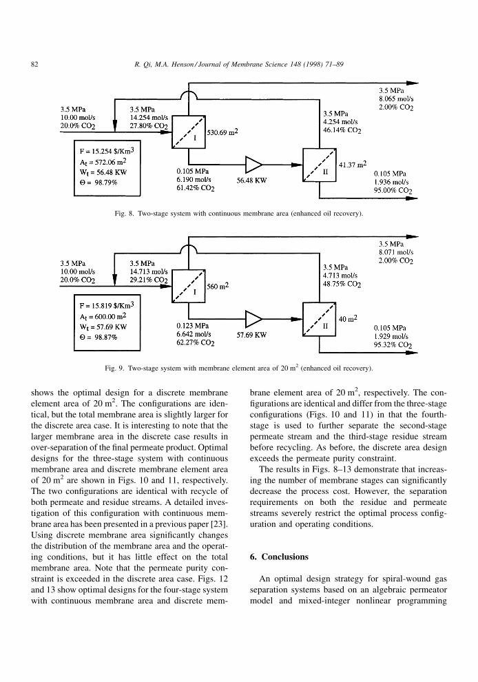
shows the optimal design for a discrete membrane
element area of 20 m2. The con®gurations are iden-
tical, but the total membrane area is slightly larger for
the discrete area case. It is interesting to note that the
larger membrane area in the discrete case results in
over-separation of the ®nal permeate product. Optimal
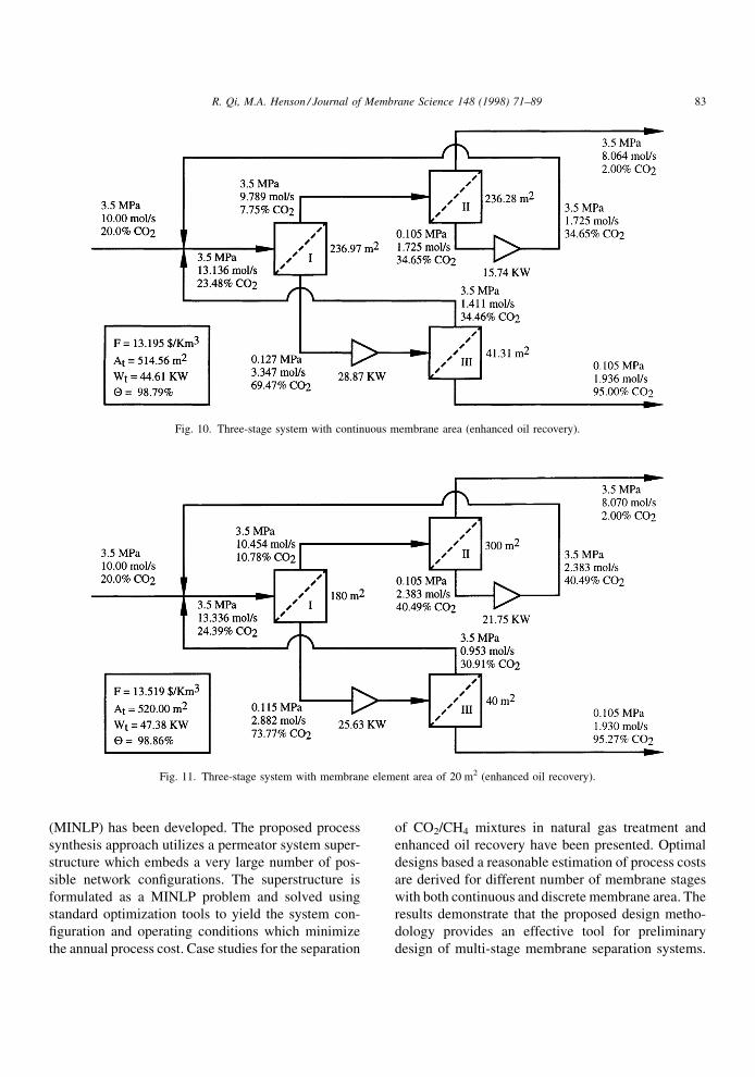
designs for the three-stage system with continuous
membrane area and discrete membrane element area
of 20 m2 are shown in Figs. 10 and 11, respectively.
The two con®gurations are identical with recycle of
both permeate and residue streams. A detailed inves-
tigation of this con®guration with continuous mem-
brane area has been presented in a previous paper [23].
Using discrete membrane area signi®cantly changes
the distribution of the membrane area and the operat-
ing conditions, but it has little effect on the total
membrane area. Note that the permeate purity con-
straint is exceeded in the discrete area case. Figs. 12
and 13 show optimal designs for the four-stage system
with continuous membrane area and discrete mem-
brane element area of 20 m2, respectively. The con-
®gurations are identical and differ from the three-stage
con®gurations (Figs. 10 and 11) in that the fourth-
stage is used to further separate the second-stage
permeate stream and the third-stage residue stream
before recycling. As before, the discrete area design
exceeds the permeate purity constraint.
The results in Figs. 8±13 demonstrate that increas-
ing the number of membrane stages can signi®cantly
decrease the process cost. However, the separation
requirements on both the residue and permeate
streams severely restrict the optimal process con®g-
uration and operating conditions.
6. Conclusions
An optimal design strategy for spiral-wound gas
separation systems based on an algebraic permeator
model and mixed-integer nonlinear programming
Fig. 8. Two-stage system with continuous membrane area (enhanced oil recovery).
Fig. 9. Two-stage system with membrane element area of 20 m2 (enhanced oil recovery).
82 R. Qi, M.A. Henson / Journal of Membrane Science 148 (1998) 71±89
(MINLP) has been developed. The proposed process
synthesis approach utilizes a permeator system super-
structure which embeds a very large number of pos-
sible network con®gurations. The superstructure is
formulated as a MINLP problem and solved using
standard optimization tools to yield the system con-
®guration and operating conditions which minimize
the annual process cost. Case studies for the separation
of CO2/CH4 mixtures in natural gas treatment and
enhanced oil recovery have been presented. Optimal
designs based a reasonable estimation of process costs
are derived for different number of membrane stages
with both continuous and discrete membrane area. The
results demonstrate that the proposed design metho-
dology provides an effective tool for preliminary
design of multi-stage membrane separation systems.
Fig. 10. Three-stage system with continuous membrane area (enhanced oil recovery).
Fig. 11. Three-stage system with membrane element area of 20 m2 (enhanced oil recovery).
R. Qi, M.A. Henson / Journal of Membrane Science 148 (1998) 71±89 83
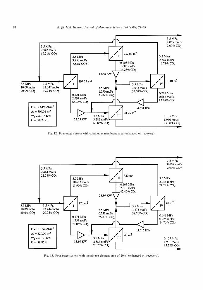
Fig. 12. Four-stage system with continuous membrane area (enhanced oil recovery).
Fig. 13. Four-stage system with membrane element area of 20m2 (enhanced oil recovery).
84 R. Qi, M.A. Henson / Journal of Membrane Science 148 (1998) 71±89
Future work will focus on optimizing the feed-side
operating pressure, as well as extending the metho-
dology to handle multicomponent gas mixtures.
7. List of symbols
a dimensionless constant defined by Eq. (5)
A membrane area for each stage (m2)
At total membrane area of system (m2)
B permeability of the spacing materials inside
the spiral-wound leaf (m2)
b dimensionless constant defined by Eq. (5)
C dimensionless constant defined by Eq. (2)
C00 permeate-side pressure parameter defined
by Eq. (3) (MPa2s/mol)
d thickness of membrane skin (m)
dm thickness of membrane leaf (m)
fcc annual capital charge (%/year)
fcp capital cost of gas-powered compressors ($/
KW)
fhv sales gas gross heating value (MJ/m3)
fmh capital cost of membrane housing ($/m2
membrane)
fmr expense of membrane replacement ($/m2
membrane)
fmt maintenance rate (%/year)
fsg utility and sales gas price ($/Km3)
fwk working capital rate (%)
F annual process cost ($/Km3)
Fcc annual capital charge ($/year)
Ffc fixed capital investment ($)
Fmr expense of membrane replacement ($/year)
Fmt maintenance expense ($/year)
Fpl value of product losses ($/year)
Fut cost of utilities ($/year)
h dimensionless leaf-length variable
K minimum number of binary variables for
integer conversion
L membrane leaf length (m)
M number of quadrature points for the integral
I( ,yr0)
N permeator stage number in configuration
NA number of membrane elements for each
stage
NAL lower bound of membrane element number
NAU upper bound of membrane element number
P feed-side pressure (MPa)
p permeate-side pressure (MPa)
pout required outlet permeate pressure
(MPa)
p0 permeate outlet pressure for each permeator
(MPa)
Q1 permeability of the more permeable compo-
nent (mol/m s Pa)
Q2 permeability of the less permeable compo-
nent (mol/m s Pa)
R dimensionless permeation factor defined by
Eq. (8)
Rg ideal gas constant (m3 Pa/kg mol K)
S slack variable in logic constraints
tm membrane life (years)
twk annual working time (days/year)
T temperature (K)
Uf feed gas flow rate for each permeator
(mol/s)
Uf0 fresh feed flow rate for each permeator
(mol/s)
Uf00 total fresh feed flow rate as processing
capacity (mol/s)
U0 flow rate of residue gas at permeator outlet
(mol/s)
Ub flow rate of residue gas as recycle stream
(mol/s)
Up flow rate of residue gas as product stream
(mol/s)
Upt total flow rate of residue product (mol/s)
UL upper bound on stream flow rate (mol/s)
UU lower bound on stream flow rate (mol/s)
V0 permeate flow rate at permeator outlet
(mol/s)
Vb flow rate of permeate gas as recycle stream
(mol/s)
Vp flow rate of permeate gas as product stream
(mol/s)
Vpt total flow rate of permeate product
(mol/s)
W membrane leaf width (m)
Wcp compressor power (KW)
Wt total compressor power (KW)
wj quadrature weights
x local feed-side concentration (mole fraction)
x0 bulk residue stream concentration at per-
meator outlet (mole fraction)
xffeed concentration for each stage (molefraction)
R. Qi, M.A. Henson / Journal of Membrane Science 148 (1998) 71±89 85
xf0 fresh feed concentration (mole fraction)
xout required CO2 concentration of residue
product (mole fraction)
xpt CO2 concentration of residue product (mole
fraction)
xr local residue concentration along outlet end
of membrane leaf (mole fraction)
y0 permeate concentration in bulk permeate
stream at permeate outlet (mole fraction)
ypt CO2 concentration of permeate product
(mole fraction)
yout required CO2 concentration of permeate
product (mole fraction)
y0 local permeate concentration on the mem-
brane surface (mole fraction)
yf0 local permeate concentration along inlet end
of membrane leaf (mole fraction)
yj0 local permeate concentration at quadrature
point j (mole fraction)
yr0 local permeate concentration along
outlet end of membrane leaf (mole
fraction)
ZA binary variable used to express discrete
membrane area
ZUb binary variable denoting the existence or
nonexistence of Ub
ZUf0 binary variable denoting the existence or
nonexistence of Uf0
ZUp binary variable denoting the existence or
nonexistence of Up
ZVb binary variable denoting the existence or
nonexistence of Vb
ZVp binary variable denoting the existence or
nonexistence of Vp
� �Q1/Q2, membrane selectivity
�p/P, ratio of permeate pressure to feed
pressure
0 �p0/P, ratio of permeate pressure to feed
pressure at permeate outlet
� viscosity of gas mixture (Pa s)
�0 V0/Uf, ratio of permeate flow to feed flow at
permeate outlet
� CH4 recovery (%)
�j quadrature points
� dimensionless feed-side flow rate
�r dimensionless feed-side flow rate at residue
outlet
�cp compressor efficiency (%)
7.1. Subscripts
i index of quadrature points for leaf length
variable h
j index of quadrature points for integral func-
tion Eq. (9)
k index of binary variables in expression of
discrete membrane area
m index of membrane stages
n index of membrane stages
Acknowledgements
Financial support from the LSU Of®ce of Research
and Development and Praxair, as well as technical
support from the GAMS Development Corporation,
are gratefully acknowledged.
Appendix A
A.1. Permeator Model Constraints
In the permeator model, the following equations are
used to de®ne parameters:
Cn � C00Uf;n=�AnP2�; n � 1; . . . ;N (40)
Rn � �Q2=d�AnP=Uf;n; n � 1; . . . ;N (41)
V0;n � Uf;n�0;n; n � 1; . . . ;N (42)
p0;n � P 0;n; n � 1; . . . ;N (43)
an � n��ÿ 1� � 1
��ÿ 1��1ÿ n� ; n � 1; . . . ;N (44)
bn � n��ÿ 1� ÿ ���ÿ 1��1ÿ n� ; n � 1; . . . ;N (45)
The permeate-side pressure distribution is obtained
from Eq. (1) using a single quadrature point at h1�0.5
2n � 2
0;n � 0:375Cn 1ÿ �r; n� �; n � 1; . . . ;N
(46)
The dimensionless feed-side ¯ow rate � at each
quadrature point j and the residue outlet, and the
integral term I are expressed as follows:
y0j;n � y0f;n � �j�y0r;n ÿ y0f;n�; j � 1; . . . ;M;
n � 1; . . . ;N (47)
86 R. Qi, M.A. Henson / Journal of Membrane Science 148 (1998) 71±89
�j;n �y0j;ny0f;n
!an1ÿ y0j;n1ÿ y0f;n
!bn�ÿ ��ÿ 1�y0j;n�ÿ ��ÿ 1�y0f;n
!;
j � 1; . . . ;M; n � 1; . . . ;N (48)
�r;n �y0r;ny0f;n
!an1ÿ y0r;n1ÿ y0f;n
!bn�ÿ ��ÿ 1�y0r;n�ÿ ��ÿ 1�y0f;n
!;
n � 1; . . . ;N (49)
In � �y0r;n ÿ y0f;n�XM
j�1
�j;nwj; n � 1; . . . ;N (50)
The relation Eq. (8) for the dimensionless permeation
factor is written as:
��1ÿ n�Rn � �ÿ ��ÿ 1�y0f;nÿ ��ÿ ��ÿ 1�y0r;n��r;n ÿ ��ÿ 1�In;
n � 1; . . . ;N (51)
The relation Eq. (11) is needed for both feed and
residue ends of the permeator:
y0f;n1ÿ y0f;n
� ��xf;n ÿ ny0f;n�1ÿ xf;n ÿ n�1ÿ y0f;n�
; n � 1; . . . ;N
(52)
y0r;n1ÿ y0r;n
� ��xr;n ÿ ny0r;n�1ÿ xr;n ÿ n�1ÿ y0r;n�
; n � 1; . . . ;N
(53)
The ¯ow rate and concentration of the ef¯uent
permeate stream from each stage are given by
Eqs. (12) and (13):
�0;n � 1ÿ �r;n; n � 1; . . . ;N (54)
y0;n � xf;n ÿ xr;n�r;n
1ÿ �r;n; n � 1; . . . ;N (55)
The ¯ow rate and concentration of the ef¯uent residue
stream are constrained by material balance equations.
A.2. Logic constraints
Logic constraints are placed on binary variables
associated with the existence or non-existence of
various interconnections. The ®rst type of logic con-
straint forces the ¯ow rate to be zero if the associated
connection is not utilized (Z�0). If the connection is
utilized (Z�1), the corresponding constraint is relaxed
to allow the ¯ow rate to assume any value up to an
upper bound (UU). These logic relations for the
feed, product, and recycle streams are expressed as
follows:
Uf0;n ÿ UUZUf0n � 0; n � 1; . . . ;N (56)
Up;n ÿ UUZUpn � 0; n � 1; . . . ;N (57)
Vp;n ÿ UUZVpn � 0; n � 1; . . . ;N (58)
Ub;m;nÿUUZUbm;n � 0; m � 1; . . . ;N; n�1; . . . ;N
(59)
Vb;m;nÿUUZVbm;n � 0; m�1; . . . ;N; n � 1; . . . ;N
(60)
The second type of logic constraint forces the binary
variable to be zero if the associated ¯ow rate becomes
zero. If the connection is utilized, the corresponding
¯ow rate can assume any value greater than a lower
bound (UL). These logic relations are expressed as:
Uf0;n ÿ ULZUf0n � 0; n � 1; . . . ;N (61)
Up;n ÿ ULZUpn � 0; n � 1; . . . ;N (62)
Vp;n ÿ ULZVpn � 0; n � 1; . . . ;N (63)
Ub;m;nÿULZUbm;n � 0; m�1; . . . ;N; n � 1; . . . ;N
(64)
Vb;m;nÿULZVbm;n � 0; m � 1; . . . ;N; n � 1; . . . ;N
(65)
In practice, UL is a small positive value which is
chosen as the minimum ¯ow rate allowed in the
system.
The ®nal type of logic constraint is associated with
the outlet permeate pressure for each stage. If the
outlet permeate stream goes to the ®nal product stream
mixer, the permeate pressure must equal the product
pressure. If the permeate stream is recycled to another
stage, the permeate pressure can assume any value less
than or equal to the feed-side pressure. By introducing
a slack variable S, these logic relations can expressed
as:
p0;n � Sn � pout; n � 1; . . . ;N (66)
0 � Sn � �Pÿ pout��1ÿ ZVpn �; n � 1; . . . ;N (67)
Note that if ZVpn � 1, then Sn�0 and p0,n�pout; if
ZVpn � 0, then 0 � Sn � Pÿ pout and pout � p0;n � P.
R. Qi, M.A. Henson / Journal of Membrane Science 148 (1998) 71±89 87
A.3. Non-negativity and integrality constraints
These constraints are used to specify the lower and
upper variable bounds to prevent unde®ned operations
(for example, division by zero) and to ensure that
the variables remain in a reasonable solution
space. Proper selection of these bounds is very impor-
tant for the ef®cient solution of mixed-integer non-
linear models. These constraints are expressed as
follows:
0 � Uf0;n; Uf;n; U0;n; V0;n; Up;n; Vp;n;
Ub;m;n; Vb;m;n; Upt; Vpt � UU (68)
An; NAn ; Rn; Cn � 0 (69)
0 � xf ;n; x0;n; y0;n; y0f ;n; y0r;n; y0j;n; xr;n � 1
(70)
0 � �0;n; 0;n; n; �r;n; �j;n � 1 (71)
ZUf0n ; ZUp
n ; ZVpn ; ZUb
m;n; ZVbm;n; ZA
n;k � 0; 1
(72)
m � 1; . . . ;N; n � 1; . . . ;N; j � 1; . . . ;M;
k � 1; . . . ;K
References
[1] R.W. Spillman, Economics of gas separation membranes,
Chem. Eng. Prog. (1989) 41±62.
[2] F.J.C. Fournie, J.P. Agostini, Permeation membranes can
efficiently replace conventional gas treatment processes, J.
Petroleum Tech. (1987) 707±712.
[3] R.T. Chern, W.J. Koros, P.S. Fedkiw, Simulation of a hollow-
fiber separation: The effects of process and design variables,
Ind. Eng. Chem. Des. Dev. 24 (1985) 1015±1022.
[4] R.W. Spillman, M.G. Barrett, T.E. Cooley, Gas membrane
process optimization. In AIChE National Meeting, New
Orleans, LA, 1988.
[5] R.E. Babcock, R.W. Spillman, C.S. Goddin, T.E. Cooley,
Natural gas cleanup: A comparison of membrane and amine
treatment processes, Energy Prog. 8 (1988) 135±142.
[6] B.D. Bhide, S.A. Stern, Membrane processes for the removal
of acid gases from natural gas. I. Process configuration and
optimization of operating conditions, J. Membrane Sci. 81
(1993) 209±237.
[7] B.D. Bhide, S.A. Stern, Membrane processes for the removal
of acid gases from natural gas. II. Effect of operating
conditions, economic parameters, and membrane properties,
J. Membrane Sci. 81 (1993) 239±252.
[8] B.D. Bhide, S.A. Stern, A new evaluation of membrane
processes for the oxygen-enrichment of air. I. Identification of
optimum operating conditions and process configuration, J.
Membrane Sci. 62 (1991) 13±35.
[9] B.D. Bhide, S.A. Stern, A new evaluation of membrane
processes for the oxygen-enrichment of air. II. Effect of
economic parameters and membrane properties, J. Membrane
Sci. 81 (1991) 37±58.
[10] T. Pettersen, K.M. Lien, Design studies of membrane
permeator processes for gas separation, Gas Sep. Purif. 9
(1995) 151±169.
[11] J. Xu, R. Agrawal, Gas separation membrane cascades. I. One
compressor cascades with minimal energy losses due to
mixing, J. Membrane Sci. 112 (1996) 115.
[12] R. Agrawal, J. Xu, Gas separation membrane cascades II.
Two compressor cascades, J. Membrane Sci. 112 (1996) 129.
[13] R. Agrawal, J. Xu, Gas separation membrane cascades
utilizing limited numbers of compressors, AIChE J. 42
(1996) 2141±2154.
[14] R. Agrawal, A simplified method for synthesis of gas
separation membrane cascades with limited numbers of
compressors, Chem. Eng. Sci. 52 (1997) 1029±1044.
[15] I.E. Grossmann, M.M. Daichendt, New trends in optimiza-
tion-based approaches to process synthesis, Computers Chem.
Eng. 20 (1996) 665±683.
[16] I.E. Grossmann, Z. Kravanja, Mixed-integer nonlinear
programming techniques for process systems engineering,
Computers Chem. Eng. 19 (1995) S189±S204.
[17] C.A. Floudas, I.E. Grossmann, Algorithmic approaches to
process synthesis: Logic and global optimization, Proceed-
ings of the Foundations of Computer-Aided Design (FO-
CAD'94), Snowmass, CO, 1994, p. 198±221.
[18] C.A. Floudas, Nonlinear and Mixed-Integer Optimization.
Scientific Press, Oxford, UK, 1995.
[19] J. Viswanathan, I.E. Grossmann, A combined penalty
function and outer-approximation method for MINLP opti-
mization, Computers Chem. Engng. 14 (1990) 769±782.
[20] A. Brooke, D. Kendrick, A. Meeraus, GAMS: A User's
Guide, Scientific Press, Palo Alto, CA, 1992.
[21] R. Qi, M.A. Henson, Approximate modeling of spiral-wound
gas permeators, J. Membrane Sci. 121 (1996) 11±24.
[22] R. Qi, M.A. Henson, Modeling of spiral-wound gas
permeators for multicomponent gas separations, Ind. Eng.
Chem. Res. 36 (1997) 2320±2331.
[23] R. Qi, M.A. Henson, Optimization-based design of spiral-
wound membrane systems for CO2/CH4 separations, Sep.
Purif. Tech. 13 (1998) 209±225.
[24] C.Y. Pan, Gas separation by permeators with high-flux
asymmetric membranes, AIChE J. 29 (1983) 545±552.
[25] R.G. Rice, D.D. Do, Applied Mathematics and Modeling for
Chemical Engineers, Wiley, New York, 1995.
[26] M. Zhu, M.M. El-Halwagi, M. Al-Ahmad, Optimal design
and scheduling of flexible reverse osmosis networks, J.
Membrane Sci. 129 (1997) 161±174.
[27] B.K. Srinivas, M.M. El-Halwagi, Optimal design of perva-
poration systems for waste reduction, Computers chem.
Engng. 17 (1993) 957±970.
[28] M.S. Peters, K.D. Timmerhaus, Plant Design and Economics
for Chemical Engineers, McGraw-Hill, New York, 1980.
88 R. Qi, M.A. Henson / Journal of Membrane Science 148 (1998) 71±89
[29] I. Quesada, I.E. Grossmann, A LP/NLP based branch and
bound algorithm for convex MINLP optimization problems,
Computers Chem. Engng. 16 (1992) 937±947.
[30] A.L. Lee, H.L. Feldkirchner, Development of a database for
advanced processes to remove carbon dioxide from subqu-
ality natural gas. Topical Report GRI-93/0247, Gas Research
Institute, 1993.
[31] A.L. Lee, H.L. Feldkirchner, S.A. Stern, A.Y. Houde, J.P.
Gamez, H.S. Meyer, Field tests of membrane modules for the
separation of carbon dioxide for low-quality natural gas, Gas
Sep. Purif. 9 (1995) 35±43.
R. Qi, M.A. Henson / Journal of Membrane Science 148 (1998) 71±89 89