Embed Size (px)
Citation preview
Advanced Membrane Design for OxygenAdvanced Membrane Design for Oxygen SeparationR. Kriegel, M. Schulz, K. Ritter, L. Kiesel, U. Pippardt, M. Stahn, I. Voigt
Fraunhofer Institute for Ceramic Technologies and Systems, Hermsdorf
© Fraunhofer IKTS
Outline
1. Manufacturing of ceramic components2. Special material properties3 Modeling3. Modeling4. Testing of state of the art membranes5. Components with complex geometry6. Conclusions
+
© Fraunhofer IKTS
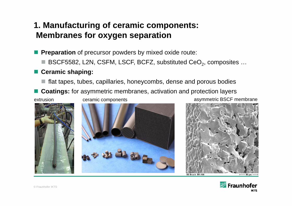
1. Manufacturing of ceramic components: M b f tiMembranes for oxygen separation
Preparation of precursor powders by mixed oxide route: BSCF5582, L2N, CSFM, LSCF, BCFZ, substituted CeO2, composites …
Ceramic shaping: fl t t t b ill i h b d d b di flat tapes, tubes, capillaries, honeycombs, dense and porous bodies
Coatings: for asymmetric membranes, activation and protection layersextrusion ceramic components asymmetric BSCF membrane
© Fraunhofer IKTS
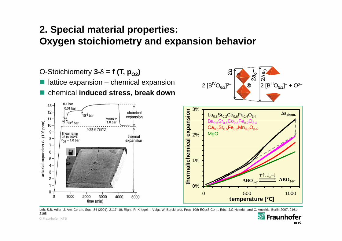
2. Special material properties: O t i hi t d i b h iOxygen stoichiometry and expansion behavior
2a2a00++
22aa 002a2a 00
2 [BIVO6/2]2– ®® 2 [BIIIO5/2]– + O2–
O-Stoichiometry 3- = f (T, pO2) lattice expansion – chemical expansion chemical induced stress break down chemical induced stress, break down
3%
sion
Ba Sr Co Fe OLa0.8Sr0.2Co0.6Fe0.4O3-
chem.
2%
ical
exp
an
Ba0.5Sr0.5Co0.8Fe0.2O3-Ca0.5Sr0.5Fe0.2Mn0.8O3-MgO
1%
rmal
/che
m
T p =
0%0 500 1000
temperature [°C]
ther ABO3-‘ ABO3-‘‘
T , pO2=
© Fraunhofer IKTS
Left: S.B. Adler: J. Am. Ceram. Soc., 84 (2001), 2117–19; Right: R. Kriegel, I. Voigt, W. Burckhardt, Proc. 10th ECerS Conf., Eds.: J.G.Heinrich and C. Aneziris, Berlin 2007, 2161-2168
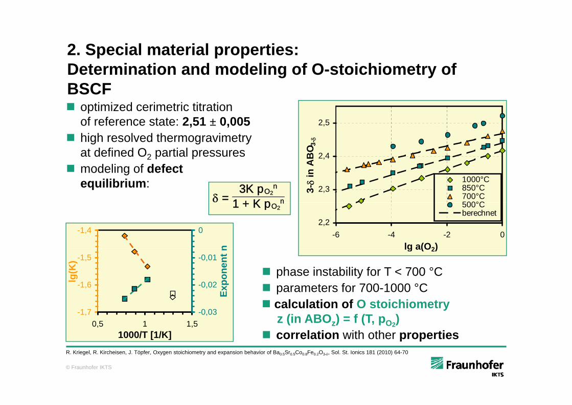
2. Special material properties:D t i ti d d li f O t i hi t fDetermination and modeling of O-stoichiometry of BSCF optimized cerimetric titration
2 4
2,5
BO 3
-
optimized cerimetric titration of reference state: 2,51 ± 0,005
high resolved thermogravimetry at defined O2 partial pressures
=3K pO2
n
1 + K p n2,3
2,4
3-
in A
B
1000°C850°C700°C500°C
at defined O2 partial pressures modeling of defect
equilibrium:1 + K pO2
n
2,2-6 -4 -2 0
lg a(O2)
500°Cberechnet
-1,4 0n lg a(O2)
-1,6
-1,5
lg(K
)
-0,02
-0,01
Expo
nent
n
phase instability for T < 700 °C parameters for 700-1000 °C
-1,70,5 1 1,5
1000/T [1/K]
-0,03
E
calculation of O stoichiometry z (in ABOz) = f (T, pO2)
correlation with other properties
© Fraunhofer IKTS
p pR. Kriegel, R. Kircheisen, J. Töpfer, Oxygen stoichiometry and expansion behavior of Ba0.5Sr0.5Co0.8Fe0.2O3-, Sol. St. Ionics 181 (2010) 64-70
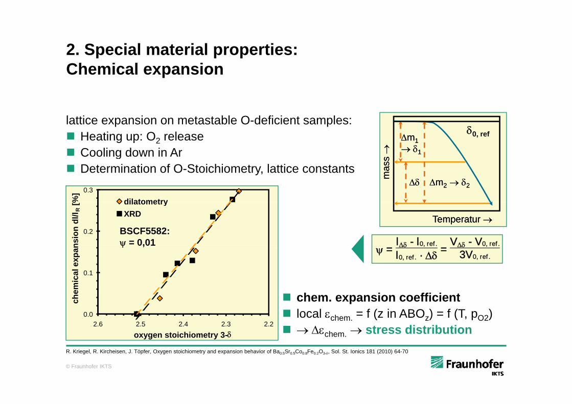
2. Special material properties: Ch i l iChemical expansion
mm11 11
0, reflattice expansion on metastable O-deficient samples: Heating up: O2 release Cooling down in Ar
mas
s m
ass
mm22 22
Cooling down in Ar Determination of O-Stoichiometry, lattice constants
0.3
%]
dilatometry
Temperatur Temperatur
=l - l0, ref . =
V - V0, ref .
0.2
nsio
n dl
/l R[% dilatometry
XRD
BSCF5582: = 0,01
= l0, ref . · = 3V0, ref .
h i ffi i t
0.1
emic
al e
xpa
chem. expansion coefficient local chem. = f (z in ABOz) = f (T, pO2) chem. stress distribution
0.02.22.32.42.52.6
oxygen stoichiometry 3-
che
© Fraunhofer IKTS
R. Kriegel, R. Kircheisen, J. Töpfer, Oxygen stoichiometry and expansion behavior of Ba0.5Sr0.5Co0.8Fe0.2O3-, Sol. St. Ionics 181 (2010) 64-70
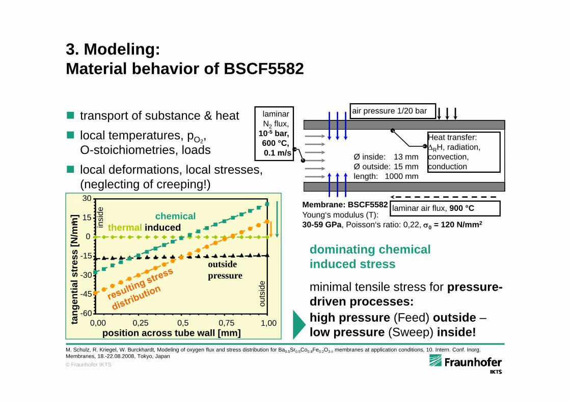
3. Modeling:M t i l b h i f BSCF5582Material behavior of BSCF5582
air pressure 1/20 bar transport of substance & heat local temperatures, pO2
, O-stoichiometries, loads
laminar N2 flux,
10-5 bar, 600 °C, 0.1 m/s Ø inside: 13 mm
Heat transfer: RH, radiation, convection
air pressure 1/20 bar
30
, local deformations, local stresses,
(neglecting of creeping!)
0.1 m/s Ø inside: 13 mmØ outside: 15 mmlength: 1000 mm
convection, conduction
0
15
[N/m
m]
2 insi
de
thermal inducedchemical
Membrane: BSCF5582Young‘s modulus (T):30-59 GPa, Poisson‘s ratio: 0,22, 0 = 120 N/mm2
laminar air flux, 900 °C
d i ti h i l
45
-30
-15
tial s
tres
s
outside pressure
side
dominating chemical induced stress
minimal tensile stress for pressure-
0,00 0,25 0,5 0,75 1,00position across tube wall [mm]
-60
-45
tang
ent
outs
pdriven processes:high pressure (Feed) outside –low pressure (Sweep) inside!
© Fraunhofer IKTS
[ ] p ( p)M. Schulz, R. Kriegel, W. Burckhardt, Modeling of oxygen flux and stress distribution for Ba0.5Sr0.5Co0.8Fe0.2O3 membranes at application conditions, 10. Intern. Conf. Inorg. Membranes, 18.-22.08.2008, Tokyo, Japan
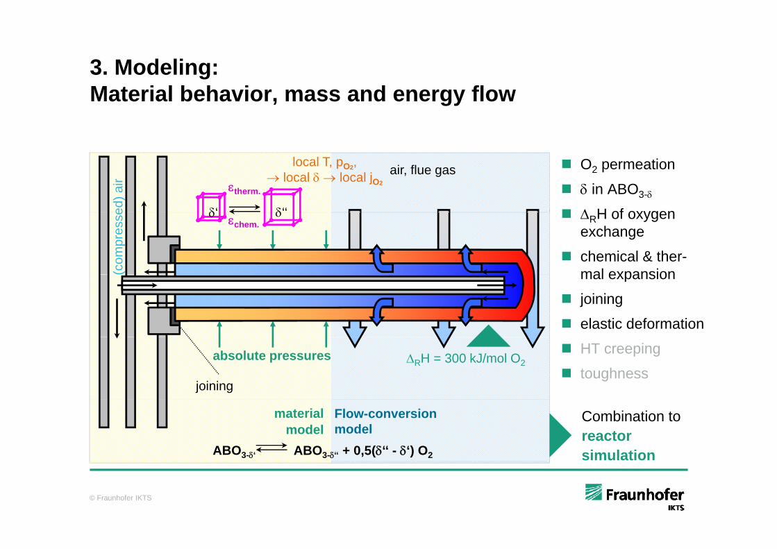
3. Modeling: M t i l b h i d flMaterial behavior, mass and energy flow
air, flue gas
ed) a
ir
local T, pO2, local local jO2therm.
‘‘‘
O2 permeation
in ABO3-
H of oxygen
(com
pres
se chem. RH of oxygen
exchange
chemical & ther-mal expansion
-DH
mal expansion
joining
elastic deformation
RH = 300 kJ/mol O2absolute pressures
joining
HT creeping
toughness
Combination to reactorsimulation
Flow-conversion model
materialmodel
ABO3-‘‘ + 0,5(‘‘ - ‘) O2ABO3-‘
© Fraunhofer IKTS
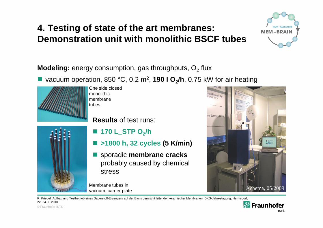
4. Testing of state of the art membranes:D t ti it ith lithi BSCF t bDemonstration unit with monolithic BSCF tubes
Modeling: energy consumption, gas throughputs, O2 flux
vacuum operation, 850 °C, 0.2 m2, 190 l O2/h, 0.75 kW for air heatingOne side closedOne side closedmonolithic membrane tubes
Results of test runs:
170 L_STP O2/h >1800 h, 32 cycles (5 K/min) sporadic membrane cracks
probably caused by chemical
Achema, 05/2009Membrane tubes in vacuum carrier plate
p y ystress
© Fraunhofer IKTS
vacuum carrier plateR. Kriegel: Aufbau und Testbetrieb eines Sauerstoff-Erzeugers auf der Basis gemischt leitender keramischer Membranen, DKG-Jahrestagung, Hermsdorf, 22.-24.03.2010
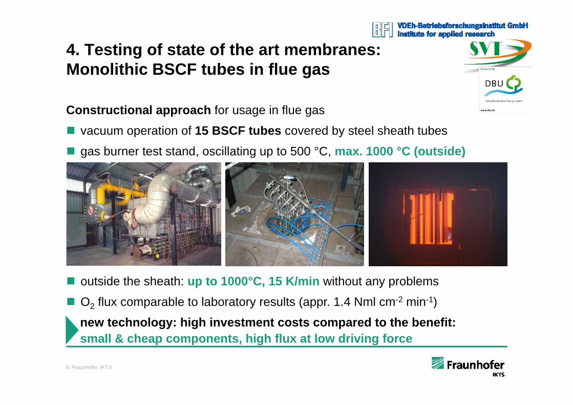
4. Testing of state of the art membranes:M lithi BSCF t b i fl
Constructional approach for usage in flue gas
Monolithic BSCF tubes in flue gas
Constructional approach for usage in flue gas
vacuum operation of 15 BSCF tubes covered by steel sheath tubes
gas burner test stand, oscillating up to 500 °C, max. 1000 °C (outside)g , g p , ( )
outside the sheath: up to 1000°C, 15 K/min without any problems
O2 flux comparable to laboratory results (appr. 1.4 Nml cm-2 min-1)
new technology: high investment costs compared to the benefit: small & cheap components high flux at low driving force
© Fraunhofer IKTS
small & cheap components, high flux at low driving force
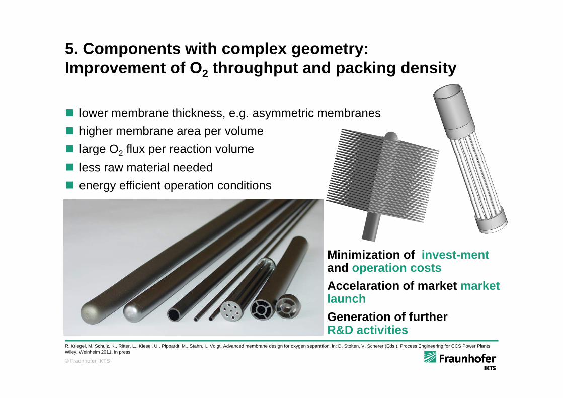
5. Components with complex geometry:I t f O th h t d ki d itImprovement of O2 throughput and packing density
l b thi k t i b lower membrane thickness, e.g. asymmetric membranes higher membrane area per volume large O2 flux per reaction volumeg 2 p less raw material needed energy efficient operation conditions
Minimization of invest-ment and operation costsAccelaration of market marketAccelaration of market market launchGeneration of further R&D activities
© Fraunhofer IKTS
R. Kriegel, M. Schulz, K., Ritter, L., Kiesel, U., Pippardt, M., Stahn, I., Voigt, Advanced membrane design for oxygen separation. in: D. Stolten, V. Scherer (Eds.), Process Engineering for CCS Power Plants, Wiley, Weinheim 2011, in press
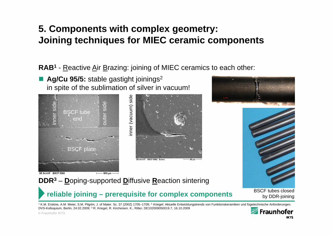
5. Components with complex geometry: J i i t h i f MIEC i tJoining techniques for MIEC ceramic components
RAB1 - Reactive Air Brazing: joining of MIEC ceramics to each other: Ag/Cu 95/5: stable gastight joinings2
in spite of the sublimation of silver in vacuum!p
BSCF tube der
sid
e
er s
ide
cuum
) sid
e
end
inn
out
inne
r (va
BSCF plate
DDR3 – Doping-supported Diffusive Reaction sinteringBSCF tubes closed
by DDR-joiningreliable joining – prerequisite for complex components
© Fraunhofer IKTS
1 K.M. Erskine, A.M. Meier, S.M. Pilgrim, J. of Mater. Sc. 37 (2002) 1705–1709; 2. Kriegel: Aktuelle Entwicklungstrends von Funktionskeramiken und fügetechnische Anforderungen. DVS-Kolloquium, Berlin, 24.02.2009; 3 R. Kriegel, R. Kircheisen. K., Ritter, DE102009050019.7, 16.10.2009
by DDR joiningj g p q p p
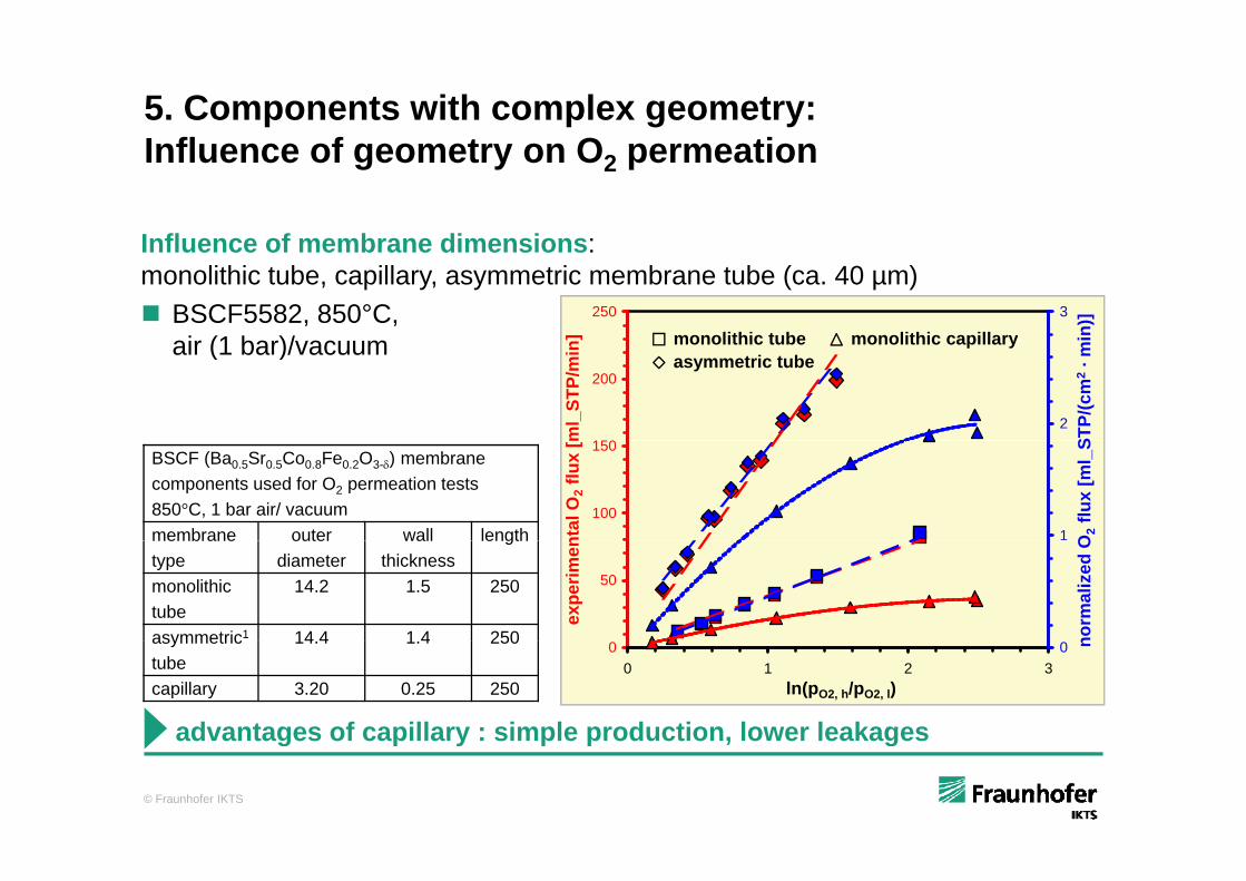
5. Components with complex geometry: I fl f t O tiInfluence of geometry on O2 permeation
Influence of membrane dimensions:Influence of membrane dimensions: monolithic tube, capillary, asymmetric membrane tube (ca. 40 µm) BSCF5582, 850°C,
air (1 bar)/ ac m in)]
monolithic tube monolithic capillary250
]
3
air (1 bar)/vacuum
STP/
(cm
2· m
monolithic tubeasymmetric tube
monolithic capillary
150
200
ml_
STP/
min
2
BSCF (Ba0.5Sr0.5Co0.8Fe0.2O3-) membrane components used for O2 permeation tests 850°C, 1 bar air/ vacuummembrane outer wall length O
2flu
x [m
l_S
100
150
ntal
O2 f
lux
[m
1membranetype
outer diameter
wall thickness
length
monolithictube
14.2 1.5 250
asymmetric1 14 4 1 4 250 norm
aliz
ed O
50ex
perim
en
asymmetrictube
14.4 1.4 250
capillary 3.20 0.25 250
n00 1 2 3
ln(pO2, h/pO2, l)
0
advantages of capillary : simple production, lower leakages
© Fraunhofer IKTS
advantages of capillary : simple production, lower leakages
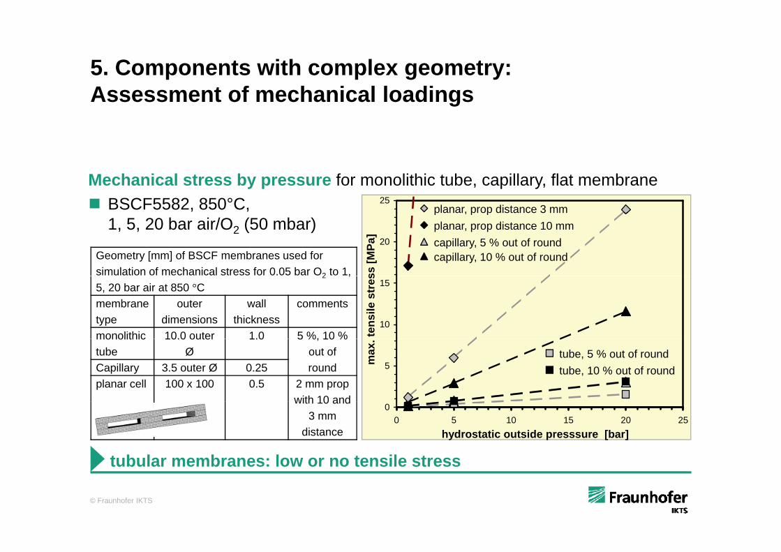
5. Components with complex geometry:A t f h i l l diAssessment of mechanical loadings
Mechanical stress by pressure for monolithic tube, capillary, flat membrane BSCF5582, 850°C, 25
planar, prop distance 3 mm1, 5, 20 bar air/O2 (50 mbar)
Geometry [mm] of BSCF membranes used for simulation of mechanical stress for 0.05 bar O2 to 1,
20
ss [M
Pa]
planar, prop distance 10 mmp , p p
capillary, 10 % out of roundcapillary, 5 % out of round
2 ,5, 20 bar air at 850 °Cmembranetype
outer dimensions
wall thickness
comments
monolithic 10.0 outer 1.0 5 %, 10 %10
15
tens
ile s
tres
monolithictube
10.0 outer Ø
1.0 5 %, 10 % out of roundCapillary 3.5 outer Ø 0.25
planar cell 100 x 100 0.5 2 mm prop with 10 and
5max
. tube, 10 % out of roundtube, 5 % out of round
with 10 and 3 mm
distance
00 5 10 15 20 25
hydrostatic outside presssure [bar]
tubular membranes: low or no tensile stress
© Fraunhofer IKTS
tubular membranes: low or no tensile stress
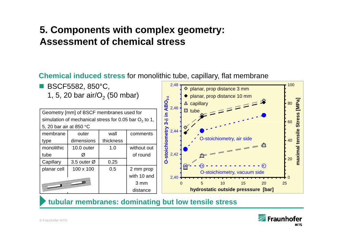
5. Components with complex geometry:A t f h i l tAssessment of chemical stress
Chemical induced stress for monolithic tube, capillary, flat membrane BSCF5582, 850°C,
1 5 20 bar air/O (50 mbar)2,48 100
planar, prop distance 3 mm1, 5, 20 bar air/O2 (50 mbar)
Geometry [mm] of BSCF membranes used for simulation of mechanical stress for 0.05 bar O2 to 1,
2,46
- in
AB
O3-
60
80
ress
[MPa
]
tube
planar, prop distance 10 mmcapillary
2 ,5, 20 bar air at 850 °Cmembranetype
outer dimensions
wall thickness
comments
monolithic 10.0 outer 1.0 without out
2,44
chio
met
ry 3
-
40
60
al te
nsile
Str
O-stoichiometry, air side
monolithictube
10.0 outer Ø
1.0 without out of round
Capillary 3.5 outer Ø 0.25planar cell 100 x 100 0.5 2 mm prop
with 10 and 2 40
2,42
O-s
toic
0
20
max
ima
O-stoichiometry, vacuum sidewith 10 and
3 mm distance
2,400 5 10 15 20 25
hydrostatic outside presssure [bar]
0
tubular membranes: dominating but low tensile stress
© Fraunhofer IKTS
tubular membranes: dominating but low tensile stress
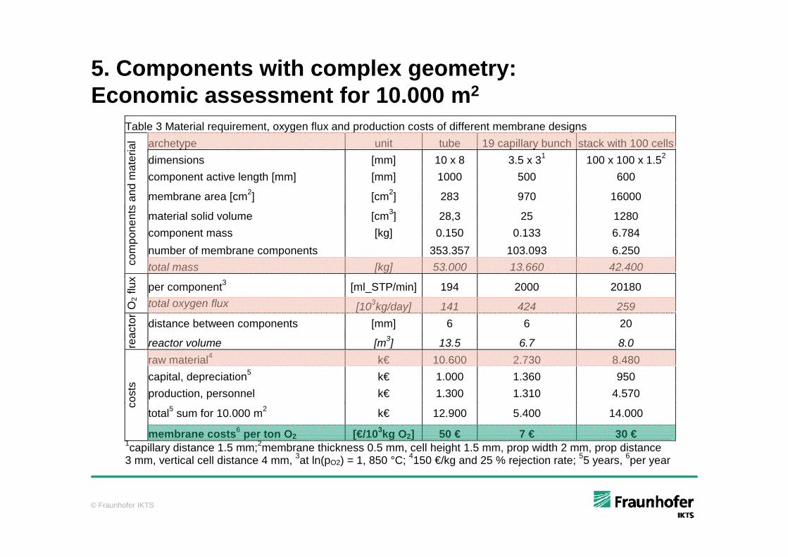
5. Components with complex geometry:E i t f 10 000 2Economic assessment for 10.000 m2
Table 3 Material requirement, oxygen flux and production costs of different membrane designs archetype unit tube 19 capillary bunch stack with 100 cells
rial
dimensions [mm] 10 x 8 3.5 x 31 100 x 100 x 1.52 component active length [mm] [mm] 1000 500 600
membrane area [cm2] [cm2] 283 970 16000
material solid volume [cm3] 28 3 25 1280nts
and
mat
er
material solid volume [cm ] 28,3 25 1280component mass [kg] 0.150 0.133 6.784 number of membrane components 353.357 103.093 6.250
com
pone
n
total mass [kg] 53.000 13.660 42.400
x
per component3 [ml_STP/min] 194 2000 20180
O2 f
lux
total oxygen flux [103kg/day] 141 424 259 distance between components [mm] 6 6 20
eact
or
reactor volume [m3] 13 5 6 7 8 0re reactor volume [m ] 13.5 6.7 8.0raw material4 k€ 10.600 2.730 8.480 capital, depreciation5 k€ 1.000 1.360 950 production, personnel k€ 1.300 1.310 4.570
cost
s
total5 sum for 10.000 m2 k€ 12.900 5.400 14.000
c
membrane costs6 per ton O2 [€/103kg O2] 50 € 7 € 30 € 1capillary distance 1.5 mm;2membrane thickness 0.5 mm, cell height 1.5 mm, prop width 2 mm, prop distance 3 mm, vertical cell distance 4 mm, 3at ln(pO2) = 1, 850 °C; 4150 €/kg and 25 % rejection rate; 55 years, 6per year
© Fraunhofer IKTS
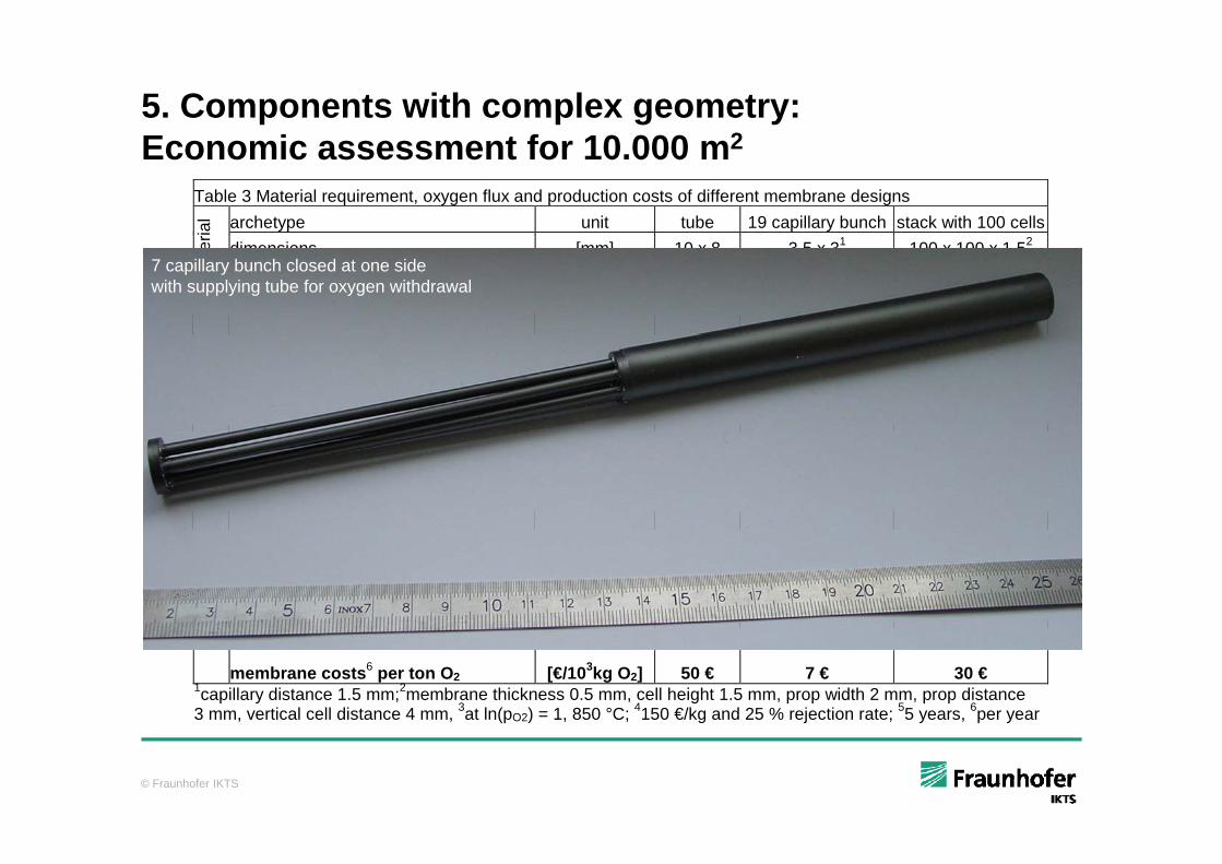
5. Components with complex geometry:E i t f 10 000 2Economic assessment for 10.000 m2
Table 3 Material requirement, oxygen flux and production costs of different membrane designs archetype unit tube 19 capillary bunch stack with 100 cells
rial
dimensions [mm] 10 x 8 3.5 x 31 100 x 100 x 1.52 component active length [mm] [mm] 1000 500 600
membrane area [cm2] [cm2] 283 970 16000
material solid volume [cm3] 28 3 25 1280nts
and
mat
er
7 capillary bunch closed at one side with supplying tube for oxygen withdrawal
material solid volume [cm ] 28,3 25 1280component mass [kg] 0.150 0.133 6.784 number of membrane components 353.357 103.093 6.250
com
pone
n
total mass [kg] 53.000 13.660 42.400
x
per component3 [ml_STP/min] 194 2000 20180
O2 f
lux
total oxygen flux [103kg/day] 141 424 259 distance between components [mm] 6 6 20
eact
or
reactor volume [m3] 13 5 6 7 8 0re reactor volume [m ] 13.5 6.7 8.0raw material4 k€ 10.600 2.730 8.480 capital, depreciation5 k€ 1.000 1.360 950 production, personnel k€ 1.300 1.310 4.570
cost
s
total5 sum for 10.000 m2 k€ 12.900 5.400 14.000
c
membrane costs6 per ton O2 [€/103kg O2] 50 € 7 € 30 € 1capillary distance 1.5 mm;2membrane thickness 0.5 mm, cell height 1.5 mm, prop width 2 mm, prop distance 3 mm, vertical cell distance 4 mm, 3at ln(pO2) = 1, 850 °C; 4150 €/kg and 25 % rejection rate; 55 years, 6per year
© Fraunhofer IKTS
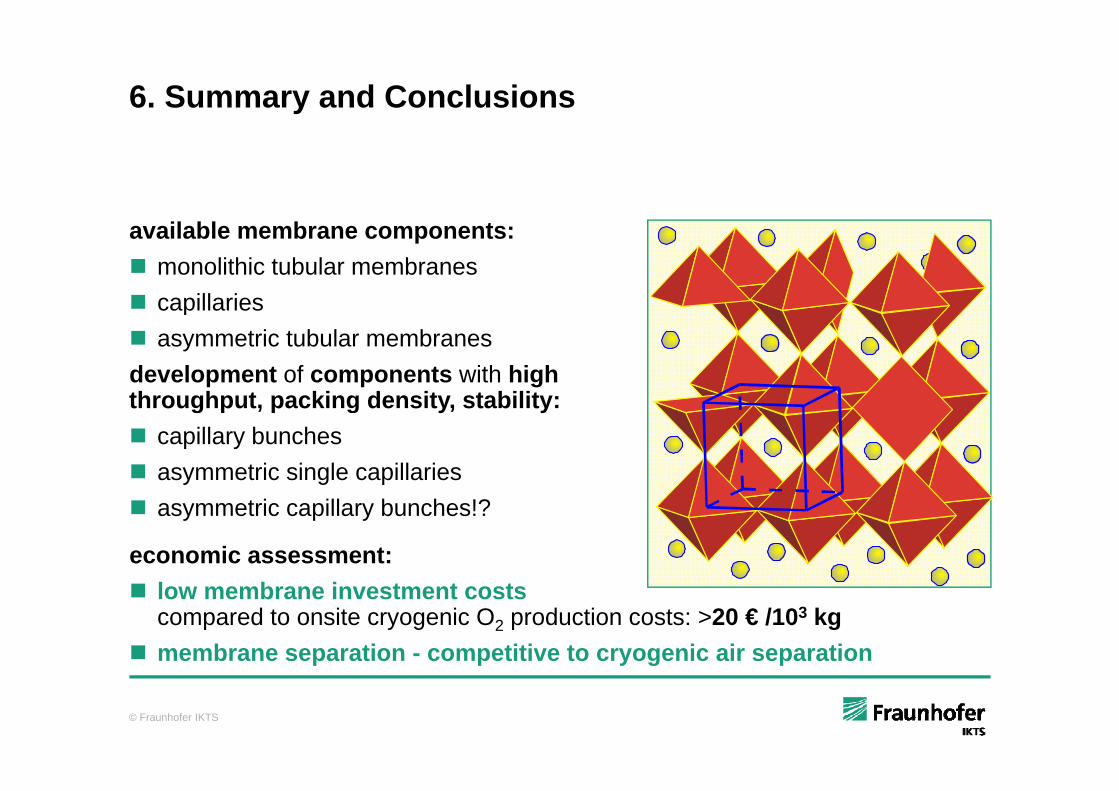
6. Summary and Conclusions
available membrane components: monolithic tubular membranes capillaries capillaries asymmetric tubular membranesdevelopment of components with high thro ghp t packing densit stabilitthroughput, packing density, stability: capillary bunches asymmetric single capillaries asymmetric capillary bunches!?
economic assessment: low membrane investment costs
compared to onsite cryogenic O2 production costs: >20 € /103 kg membrane separation - competitive to cryogenic air separation
© Fraunhofer IKTS
p p y g p