Embed Size (px)
Citation preview
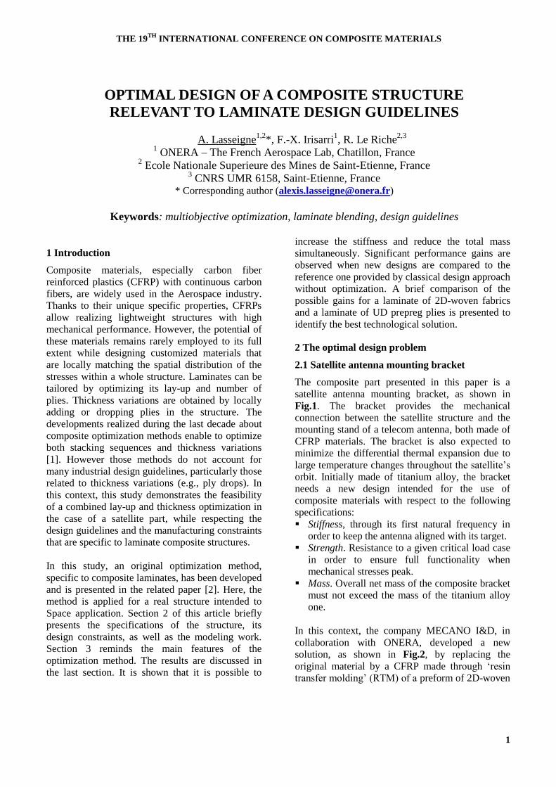
THE 19TH
INTERNATIONAL CONFERENCE ON COMPOSITE MATERIALS
1
1 Introduction
Composite materials, especially carbon fiber
reinforced plastics (CFRP) with continuous carbon
fibers, are widely used in the Aerospace industry.
Thanks to their unique specific properties, CFRPs
allow realizing lightweight structures with high
mechanical performance. However, the potential of
these materials remains rarely employed to its full
extent while designing customized materials that
are locally matching the spatial distribution of the
stresses within a whole structure. Laminates can be
tailored by optimizing its lay-up and number of
plies. Thickness variations are obtained by locally
adding or dropping plies in the structure. The
developments realized during the last decade about
composite optimization methods enable to optimize
both stacking sequences and thickness variations
[1]. However those methods do not account for
many industrial design guidelines, particularly those
related to thickness variations (e.g., ply drops). In
this context, this study demonstrates the feasibility
of a combined lay-up and thickness optimization in
the case of a satellite part, while respecting the
design guidelines and the manufacturing constraints
that are specific to laminate composite structures.
In this study, an original optimization method,
specific to composite laminates, has been developed
and is presented in the related paper [2]. Here, the
method is applied for a real structure intended to
Space application. Section 2 of this article briefly
presents the specifications of the structure, its
design constraints, as well as the modeling work.
Section 3 reminds the main features of the
optimization method. The results are discussed in
the last section. It is shown that it is possible to
increase the stiffness and reduce the total mass
simultaneously. Significant performance gains are
observed when new designs are compared to the
reference one provided by classical design approach
without optimization. A brief comparison of the
possible gains for a laminate of 2D-woven fabrics
and a laminate of UD prepreg plies is presented to
identify the best technological solution.
2 The optimal design problem
2.1 Satellite antenna mounting bracket
The composite part presented in this paper is a
satellite antenna mounting bracket, as shown in
Fig.1. The bracket provides the mechanical
connection between the satellite structure and the
mounting stand of a telecom antenna, both made of
CFRP materials. The bracket is also expected to
minimize the differential thermal expansion due to
large temperature changes throughout the satellite’s
orbit. Initially made of titanium alloy, the bracket
needs a new design intended for the use of
composite materials with respect to the following
specifications:
Stiffness, through its first natural frequency in
order to keep the antenna aligned with its target.
Strength. Resistance to a given critical load case
in order to ensure full functionality when
mechanical stresses peak.
Mass. Overall net mass of the composite bracket
must not exceed the mass of the titanium alloy
one.
In this context, the company MECANO I&D, in
collaboration with ONERA, developed a new
solution, as shown in Fig.2, by replacing the
original material by a CFRP made through ‘resin
transfer molding’ (RTM) of a preform of 2D-woven
OPTIMAL DESIGN OF A COMPOSITE STRUCTURE
RELEVANT TO LAMINATE DESIGN GUIDELINES
A. Lasseigne1,2
*, F.-X. Irisarri1, R. Le Riche
2,3
1 ONERA – The French Aerospace Lab, Chatillon, France
2 Ecole Nationale Superieure des Mines de Saint-Etienne, France
3 CNRS UMR 6158, Saint-Etienne, France
* Corresponding author ([email protected])
Keywords: multiobjective optimization, laminate blending, design guidelines

2
fabrics. This new solution resulted in reducing the
mass by 35%. This result was achieved without
numerical optimization. Prototypes of the new
bracket have been built and tested to validate the
concept and its performance, with satisfactory
results. The purpose of this work is to explore the
opportunities for improvement provided by the
parametric optimization of the bracket.
2.2 Formulation of the optimization problem
The multiobjective optimization problem of a
laminate generally consists in finding the possible
trade-offs between two or more objectives while
manipulating variables, such as the number of plies,
their order and their orientations. This differentiates
it from the feasibility problem solved before the
design step. A constrained multicriteria
optimization problem can be formulated from the
specifications detailed in section 2.1. The objectives
are to maximize the first natural frequency and
minimize the total mass of the bracket. The
optimization variables are the stacking sequences,
the order of the inserted plies, and the number of
plies per zone. These zones represent distinct
regions of the bracket where its thickness and
material properties do not vary. Each zone may be
directly identified from the geometry of the
composite structure. Constraints are divided into
two categories. The first one gathers analysis
constraints, that are most likely mechanical
quantities to compute, and often as costly as
evaluations of the objectives. In the case of this
study, a simple failure criterion is required. The
second category gathers design constraints; here
design guidelines; which intervenes essentially
while generating a solution, with relatively low
costs. These allow introducing notions of composite
know-how in the optimization process to get closer
to the reality of the design problem, but also
integrating manufacturing constraints while solving
the problem. All these constraints contribute to
result in feasible composite solutions.
2.3 Laminate design guidelines
The laminate design guidelines, created from
known manufacturing issues and feedbacks in the
industry [3,4,5], make a representative set of
industrial constraints for composite structure pre-
design.
The laminate design guidelines, particularly
restrictive on the combinations and permutations
about stacking sequence variables, may be
summarized as follows:
Symmetry of the sequence about the mid-plane.
This guideline aims at eliminating the couplings
between membrane and bending behavior, and
avoiding residual strains that may result within
the laminate.
Balance of the sequence between +θ° and –θ°
plies. This guideline aims at eliminating the in-
plane couplings between shear and traction.
Contiguity, i.e. no more than two plies with the
same orientation should be stacked together.
This guideline aims at reducing the damage
phenomena sensitive to the thickness of the
layers, such as free edges effects or matrix
cracking.
Disorientation limited to 45° between two plies.
This rule minimizes the effects of interlaminar
shear, and limits the problems of delamination at
free edges.
A proportion of 10% for each 0°, ±45° and 90°
oriented plies. This guideline prevents that the
behavior of the matrix becomes dominant on the
overall behavior of the laminate in some
directions, and minimizes the Poisson ration of
the whole laminate.
Damage tolerance improvement through ±45°-
oriented surface plies protecting the most
stressed plies whose orientations are closer to
the main loading direction. This guideline aims
at limiting the consequences of any surface
damage and possible scratches.
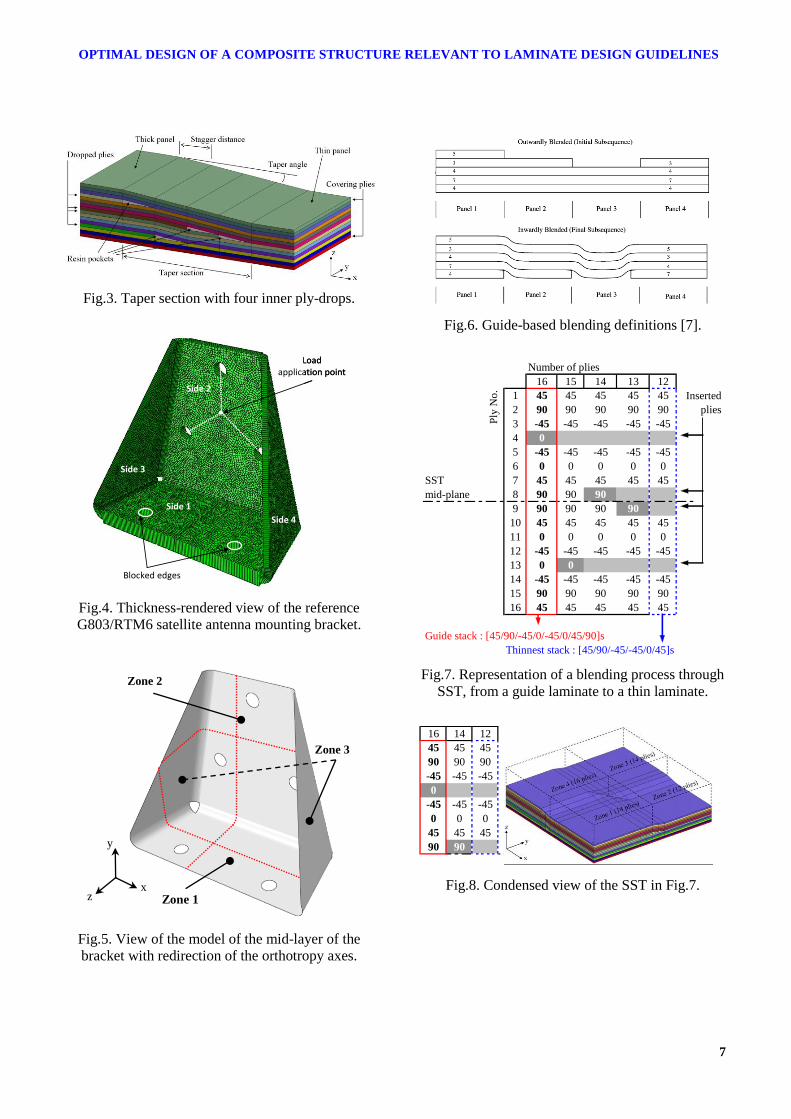
Thickness variations along the structure are ensured
by tapering the laminate through ply drop-off as
illustrated in Fig.3. Dropping a ply off may locally
weaken the structure through delamination. So
sequencing the ply drops is a task to achieve with
caution, considering six ply-drop design guidelines
intended for aerospace structures:
Covering the laminate with continuous surface
plies,
Taper angle smoothed to 7°, i.e. a minimal
stagger distance about eight times the total
thickness of all the plies dropped,
Dropping off a maximum of two plies at the
same time,
Adjacent ply drops limited to three,

3
OPTIMAL DESIGN OF A COMPOSITE STRUCTURE RELEVANT TO LAMINATE DESIGN GUIDELINES
Ply drops alternatively far from and close to the
mid-plane,
Laminate design guidelines to extend to tapers.
These guidelines also make the structure more
resistant to micro-buckling and improve their
manufacturability.
In addition to these local guidelines, two more
global rules exist, specific to taper composites:
Continuity, i.e. all the plies from the thinner
panel are expected to be kept within the
structure to ensure structural continuity.
Δn-rule, i.e. the number ply drops is limited
between distinct zones to minimize stress
concentrations.
2.4 Model and parameters
The pre-design FE model consists in a shell model
of the composite part mid-layer. The model is
developed with ABAQUS as shown in Fig.4. The
mesh is composed of reduced integration
quadrangular shell elements. Thicknesses and
composite lay-ups can be assigned to each element
or element set. As a consequence, stacking
sequences are parameterized within the model
without modifying the mesh. Thus, the
parameterization of the model only consists in
composite lay-up definition associated with a set of
elements.
The connection from the bracket to the satellite is
modeled through blocking all the degrees of
freedom of the nodes of the edges of the holes on
side #1. For each hole of side #2, the nodes of the
circumference are connected through rigid links to a
reference point located at the center of the hole. All
the three reference points, corresponding to the
three holes on side #2, are connected to a fourth one
located at their isobarycenter. The efforts are
inserted at this reference point.
Two different analyzes are performed for each
evaluation of a solution. A linear elastic static
analysis is done in order to evaluate the resistance
of the structure to a critical load case indicated in
the specifications. A fragile failure criterion results
from the post-treatment of the previous calculation.
Here, a Tsai-Hill failure criterion is used. The first
natural frequency is calculated from a modal
analysis with small perturbations performed with
the unloaded structure. The mass is estimated
through the densities of the materials and the
volume calculation tools provided by the software.
The reference bracket suggested by MECANO I&D
is realized from cut plies depending on different
perimeters of pattern with variable complexity.
These plies are successively formed through folding
on male or female molding dies and stacked as two
dry performs, slightly powdered, to be assembled
when the RTM mold is closed. In order to
transcribe the reality of this process in the model, it
is necessary to take into account the shapes of the
patterns and the folding inclinations realized to
define the local orientations of the material within
each zone of the structure. Indeed, the angle
between sides #1 and #3 (or #4) is an acute angle
whereas sides #2 and #3 (or #4) trace an obtuse
angle. These angles imply a redirection of the
orthotropy axes (1,2,3) of the material in
accordance with the projection of the global
coordinates (x,y,z) on the sides of the bracket. This
redirection evolves within the fillets’ radii between
two sides, as illustrated in Fig.5.
3 Optimization of the stacking sequences and
tapering through ply-drop off
3.1 Ply-drop management through stacking
sequence tables
The local variations of stiffness in laminated
structures are obtained through ply drops. The
design guidelines listed in section 2.3 entail that the
whole stack of the thinnest zone of the structure
runs uninterruptedly through the others. Moreover,
in order to ensure the structural integrity of the part,
it is forbidden to cut a ply to change the fiber
direction. Such issue is known in the literature as
laminate blending. The notion of laminate blending
has been introduced for the first time in [6].
Different strategies to solve this problem have been
suggested in the literature [1,2]. The most
successful method is currently the guide-based
blending presented in [7]. This method consists in
defining all the stacking sequences of the structure
from the thickest one only, also known as guiding
stack. All the thinner laminates are defined by
deleting contiguous stacks of plies form the guide
laminate, starting from the surface of the guide
stack (‘outer blending’), or from its mid-layer

4
(‘inner blending’), as illustrated in Fig.6. Hence,
guide-based blending allows ensuring perfectly the
continuity of the plies between the different zones
of the structure, without adding any constraints to
the optimization problem and adding only one
variable per zone (the number of dropped plies).
However, the choice to drop groups of contiguous
plies substantially restricts the search space, so that
it is impossible to optimize the order of the ply
drops through the thickness of the laminate. It is
therefore impossible to comply with the taper
design guidelines.
In order to overcome such limitation and represent
the evolution of the lay-up within the structure,
Stacking Sequence Tables (SST) are introduced in
this study. SSTs are used in aeronautic industry for
composite panels manufacturing. They are most
commonly created by experts, but here an original
use of the SSTs is presented to generalize guide-
based blending and allow the optimization of the
order and location of the ply drops within the
structure. The SST helps monitoring the succession
of the ply drops ensuring the transition between a
thick stack with Nmax plies and a thin stack with Nmin
plies. The ply drops are defined one by one. Read
from the left to the right, the SST describes a
thickness diminution, and conversely. Knowing the
distribution of the number of plies in a structure,
varying in the range [Nmin , Nmax], the SST defines
all the laminates of the structure, in the constant
thickness zones as well as in the taper since each
ply drop is described individually. The SST does
not take into account any particular stagger
distance. These are most likely represented in the
model when they are required. Using the SSTs
allows defining solutions that respect the design
guidelines. An example of such SST is shown in
Fig.7. In this study, symmetrical guiding stacks are
used exclusively. Taking advantage of the
symmetry, only the half of the SST is represented in
the following, as illustrated in Fig.8. Since SST
describes a blending process in a range of
thicknesses, it can be shared by several solutions as
long as they belong to this range. Indeed, the
structure is fully represented only if its thickness
distribution is featured in the solution.
3.2 Specialization of an EA to the joint
optimization of stacking sequence tables and
thickness distributions.
The method intended to solve the optimization
problem is built from a Pareto-based multiobjective
EA [8]. Its operating principle is sketched in Fig.9.
In this study, a specialized version of this algorithm
is developed for SST optimization [2] and applied
to the antenna mounting bracket described earlier.
Specific operators have been developed so that the
generated solutions satisfy the design guidelines
each time the algorithm iterates. For this purpose, a
specific encoding is used for the SST. The
symmetry of the guiding stack allows representing
only the half of the SST and therefore reduces the
encoding of the solutions. This encoding, illustrated
in Fig.10, consists in three chromosomes, each
corresponding to a set of optimization variables:
Chromosome Nstr represents the thickness
distribution, as total number of plies, within the
structure and consists of as many genes as there
are effective zones in the structure.
Chromosome SSTlam represents the sequence of
the guiding stack for generating the SST and
consists of Nmax/2 genes.
Chromosome SSTins represents the ranks of the
plies to be introduced to form the SST. The
insertion order is given here by numbers in
ascending order. The plies of the thin stack
cover the entire SST. This chromosome has the
same size than SSTlam and contains Nmin/2 zeros,
corresponding to plies covering the whole
structure.
4 Results
The objectives of the optimization problem
presented in this paper are to maximize the stiffness
of the antenna bracket through its first natural
frequency and to minimize its mass. The MECANO
I&D’s bracket is made of G803/RTM6, a balanced
orthotropic 2D woven fabric, whose fibers are
T300. Thus the problem is solved for G803/RTM6
then T300/914, a unidirectional prepreg ply with
transverse isotropy, to explore the possibilities that
UD offers compared to 2D material. Properties of
G803/RTM6 presented in Tab.1 are expressed in
the orthotropy axes of the ply for a fiber volume
fraction of 56%. Its in-plane properties have been

5
OPTIMAL DESIGN OF A COMPOSITE STRUCTURE RELEVANT TO LAMINATE DESIGN GUIDELINES
experimentally characterized by MECANO I&D.
Through-the-thickness properties E3, ν23 and ν31 are
assumed to be close to the transversal properties of
the unidirectional prepreg ply T300/914. Failure
properties, of the G803/RTM6 ply and the
T300/914 ply are given in Tab.2. Ply thickness is
about 0.28 mm for the G803/RTM6 and 0.158 mm
for the T300/914. The thickness, or number of plies
in each zone, is limited by at least 12 plies up to 34
plies in the case of the optimization with
G803/RTM6, and at least 18 plies up to 68 plies for
T300/914. Ply orientations are limited to the
following set of admissible values {0°, ±15°, ±30°,
±45°, ±60°, ±75° and 90°}.
The evolutionary algorithm is set to run six
thousand solution evaluations during the whole
optimization process, as outlined in Tab.3. These
are represented in the objectives space in Fig.11
and Fig.12, including optimal solutions for both
materials as red diamonds. Regarding the
optimization performed with 2D-woven fabrics,
Fig.11 shows that the algorithm converges to
solutions included in the bottom right quadrant,
where the solutions improve the reference solution
towards the two objectives. By repeating the
exercise with the UD prepreg, a significant gain in
stiffness for an equivalent mass is achieved, as
shown in Fig.13. Such increase can be explained by
the higher stiffness in the fiber direction of the
T300/914. In addition, the optimization problem has
more degrees of freedom by using UD plies.
Indeed, these are thinner and therefore more
numerous than 2D plies through the thickness of the
laminate. While increasing the number of plies,
SSTs are enlarged, as well as the number of
possible combinations and permutations of the
optimization variables. The lightest G803/RTM6
solution, whose SST is detailed in Fig.14 and the
properties listed in Tab.4, allows weight savings of
10% compared to the reference solution. The
lightest T300/914 solution performs 12%-weight
savings compared to the reference solution.
In the optimized design, it can be seen that the
tapers are located within the fillet radii connecting
the faces of the bracket. Moreover, ply drops are
distributed over a very short distance. The
representation of fillet radii is therefore restricted in
the pre-design model. However, the results of the
pre-design model are relatively satisfactory
considering the reference solution manufactured
and tested by MECANO I&D, so that the model is
considered to give fair trends over the design space.
In addition, the guidelines aiming at limiting the
risks of premature failure are used in this model to
overcome the inherent limitations of pre-design in
predicting the behavior and failure of the structure,
unlike detailed analysis. Since most of the design
guidelines have been thought for large structures,
this may call into question their relevance with this
application. They are probably pushed beyond their
range of validity in this study. For relevance,
performing a numerical validation based on a
detailed three-dimensional model, and eventually
conducting an experimental validation are expected
as future works.
5 Conclusions
This paper presents the application of an
optimization method, dedicated to variable-
thickness laminated composite structures, to a
demonstration case provided by MECANO I&D.
The method applied here has been developed in the
context of this study and described in the related
paper [2]. The demonstration case consists of a
mounting bracket designed to connect a satellite
antenna to a satellite structure. The optimization
problem is formulated based on the specifications
of the structure. A pre-design FE model of the
bracket is created in order to represent the
complexity of the structure without involving too
many details and excessive computation costs. The
problem takes into account the guidelines related to
laminate composite structures. To enforce theses
guidelines and ensure the structural continuity of
the design, stacking sequence tables are used. The
problem is solved using a multiobjective
evolutionary algorithm. A specific encoding of the
solutions is used that represents the stacking
sequences, the order of the ply insertions within the
constitutive laminates of the structure and the
thickness distribution over the whole structure. The
optimization problem is solved first for a base ply
made of a carbon/epoxy 2D-woven fabric, then
using a carbon/epoxy UD ply. This allows
exploring two different design spaces and achieving
optimal solutions which improve significantly the
reference solution. ONERA and MECANO I&D

6
are currently working together to test the method on
new designs of the antenna mounting bracket and
then validate it through the completion of a
demonstration prototype for experimental
validation.
Acknowledgement
The authors would like to thank MECANO I&D,
especially L. Bonnes and C. Mauris-Demourioux
for their support.
References
[1] H. Ghiasi, K. Fayazbakhsh, D. Pasini, L. Lessard,
“Optimum stacking sequence design of composite
materials Part II: Variable stiffness design”.
Compos. Struct., vol. 93, no. 1, pp. 1-13, 2010.
[2] F.-X. Irisarri, A. Lasseigne, F.-H. Leroy,
“Stacking sequence tables for laminate blending
optimization”. 19th
International Conference on
Composites Materials, Montreal, August 2013.
[3] MIL-HDBK-17-3F. “Military Handbook, Polymer
Matrix Composites”. US Department of Defense,
2002.
[4] J.A. Bailie, R.P. Ley, A. Pasricha. “A summary
and review of composite laminate design
guidelines“. Technical report NASA, NAS1-
19347. Northrop Grumman-Military Aircraft
Systems Division. 1997.
[5] A. Weiss, W. Trabelsi, L. Michel, J.J. Barrau, S.
Mahdi. “Influence of ply-drop location on the
fatigue behaviour of tapered composite
laminates”. Procedia Engineering, vol. 2, n°1, pp.
1105-114, 2010.
[6] B.P. Kristinsdottir, Z.B. Zabinsky, M.E. Tuttle, S.
Neogi, “Optimal design of large composite panels
with varying loads”. Compos. Struct., vol. 51, no.
1, pp 93-102, 2001.
[7] DB. Adams, LT. Watson, Z. Gürdal, CM.
Anderson-Cook, “Genetic algorithm optimization
and blending of composite laminates by locally
reducing laminate thickness”. Adv. in Eng. Soft.e,
35(1):35-43, 2004.
[8] F.-X. Irisarri, F. Laurin, F.-H. Leroy, J.-F. Maire.
“Computational strategy for multiobjective
optimization of composite stiffened panels”.
Compos. Struct., Vol. 93(3), pp. 1158-1167, 2011.
Fig.1. Design of the titanium alloy solution of the
satellite antenna mounting bracket.
Fig.2. Photographs of the CFRP solution made by
MECANO I&D (front and rear views).
Titanium alloy
solution
CFRP
solution
(front)
CFRP
solution
(rear)
7
OPTIMAL DESIGN OF A COMPOSITE STRUCTURE RELEVANT TO LAMINATE DESIGN GUIDELINES
Fig.3. Taper section with four inner ply-drops.
Side 1
Side 2
Side 3
Side 4
Blocked edges
Loadapplication point
Side 1
Side 2
Side 3
Side 4
Blocked edges
Loadapplication point
Fig.4. Thickness-rendered view of the reference
G803/RTM6 satellite antenna mounting bracket.
Fig.5. View of the model of the mid-layer of the
bracket with redirection of the orthotropy axes.
Fig.6. Guide-based blending definitions [7].
16 15 14 13 12
1 45 45 45 45 45
2 90 90 90 90 90
3 -45 -45 -45 -45 -45
4 0
5 -45 -45 -45 -45 -45
6 0 0 0 0 0
SST 7 45 45 45 45 45
mid-plane 8 90 90 90
9 90 90 90 90
10 45 45 45 45 45
11 0 0 0 0 0
12 -45 -45 -45 -45 -45
13 0 0
14 -45 -45 -45 -45 -45
15 90 90 90 90 90
16 45 45 45 45 45
Guide stack : [45/90/-45/0/-45/0/45/90]s
Inserted
plies
Thinnest stack : [45/90/-45/-45/0/45]s
Number of plies
Ply
No
.
Fig.7. Representation of a blending process through
SST, from a guide laminate to a thin laminate.
16 14 12
45 45 45
90 90 90
-45 -45 -45
0
-45 -45 -45
0 0 0
45 45 45
90 90
Fig.8. Condensed view of the SST in Fig.7.
Zone 3
Zone 2
Zone 1 x
y
z

8
Fig.9. Flow chart of the evolutionary algorithm.
Nstr 14 12 14 16
SSTlam 45 90 -45 0 -45 0 45 90
SSTins 0 0 0 2 0 0 0 1
Fig.10. Encoding of the solution in Fig.8.
Materials G803/RTM6 T300/914
E1 (GPa) 61,23 140
E2 (GPa) 61,23 10
E3 (GPa) 10,00 -
ν12 0,03 0,31
ν23 0,30 -
ν31 0,30 -
G12 (GPa) 3,46 4,40
G23 (GPa) 2,96 -
G31 (GPa) 2,96 -
µ (kg/m3) 1496 1760
Tab.1. Elastic properties of G803/RTM6 and
T300/914 plies.
Materials G803/RTM6 T300/914
Xt (Mpa) 700 1500
Yt (MPa) 690 27
Xc (MPa) -468 -900
Yc (MPa) -438 -200
S (MPa) 103 80
Tab.2. Failure properties of G803/RTM6 and
T300/914 plies.
Crossing 0.3
Mutation 0.9
Initial population 60
Current population 30
Archive population 60
Generations 200
Tab.3. Algorithm settings.
Fig.11. Solutions in the objectives space
for G803/RTM6 woven fabric.
Fig.12. Solutions in the objectives space
for T300/914 unidirectional plies.
Initialization
Evaluation
Ranking
Selection
Stop
Reproduction selection
Reproduction
Current population
Archive
tP
1tP
Initial population 0P
1tP
Variables-specific modules
Objectives-specific modules
t tP P
Empty archive vide
0P

9
OPTIMAL DESIGN OF A COMPOSITE STRUCTURE RELEVANT TO LAMINATE DESIGN GUIDELINES
700 800 900 1000 1100 120080
90
100
110
120
130
140
150
160
170
180
1st Natural Freq. (Hz)
Wei
ght (g
)
reference solution
G803/RTM6
T300/914
Fig.13. Comparison of optimal solutions.
34 32 30 28 26 24 22 20 18 16 14 12
1 45 45 45 45 45 45 45 45 45 45 45 45
2 0 0 0 0 0
3 30 30 30 30 30 30 30 30 30 30 30
4 -15 -15 -15 -15 -15 -15 -15 -15 -15
5 0 0 0 0 0 0 0 0 0 0 0 0
6 -45 -45 -45 -45
7 -30 -30
8 0 0 0 0 0 0 0 0 0 0 0 0
9 45 45 45
10 15 15 15 15 15 15 15 15
11 -30 -30 -30 -30 -30 -30 -30 -30 -30 -30
12 -45 -45 -45 -45 -45 -45 -45 -45 -45 -45 -45 -45
13 -75 -75 -75 -75 -75 -75 -75
14 75 75 75 75 75 75
15 -75 -75 -75 -75 -75 -75 -75 -75 -75 -75 -75 -75
16 75 75 75 75 75 75 75 75 75 75 75 75
17 30
Encoding : [30|12|12]
[45/0/30/-15/0/-45/-30/0/45/15/-30/-45/-75/75/-75/75/30]s [0|7|1|3|0|8|10|0|9|4|2|0|5|6|0|0|11]
Fig.14. Stacking sequence of an optimal
G803/RTM6 solution.
Ref. G803/RTM6 T300/914
Thickness
distribution (mm)
9,24
5,32
3,36
8,40
3,36
3,36
8,22
3,48
2,84
Thickness
distribution
(No. plies)
Zone 1
Zone 2
Zone 3
33
19
12
30
12
12
52
22
18
Total mass (g) 154.314 139.500 135.520
1st natural frequency
(Hz) 879 905 880
Failure criterion
max. value 0.751 0.992 0.997
Tab.4. Characteristics of the lightest solution within
the Pareto front for each material.