Embed Size (px)
Citation preview

IEEE TRANSACTIONS ON SIGNAL PROCESSING, VOL. 50, NO. 12, DECEMBER 2002 3055
Optimal Design and Placement of Pilot Symbols forChannel Estimation
Min Dong, Student Member, IEEE,and Lang Tong, Senior Member, IEEE
Abstract—The problem of designing and placing pilot symbolsfor the estimation of frequency-selective random channels is con-sidered. The channel is assumed to be a block-fading model withfinite impulse response (FIR). For both single-input single-output(SISO) and multiple-input multiple-output (MIMO) channels,under the assumption of independent and identical distributedchannel taps, the Cramér–Rao Bound (CRB) on the mean squareerror (MSE) of semi-blind channel estimators is derived andminimized with respect to pilot symbols and their placement.It is shown that the optimal strategy is to place pilot symbolssatisfying certain orthogonality condition in such a way that dataand pilot symbols with higher power are in the middle of thepacket. The results also indicate that the optimal pilot placementsare independent of channel probability distribution. For constantmodulus symbols, we show that the quasi-periodic placement andits generalization in the multiuser case turn out to be optimal.We further consider estimating channels with correlated taps andshow that the previous placement strategy is also optimal amongorthogonal pilot sequences.
Index Terms—Channel estimation, Cramér-Rao bound, optimaldesign, pilot symbols, placement schemes, semi-blind.
I. INTRODUCTION
CHANNEL estimation plays a critical role inpacket-switched wireless systems where it is often
necessary to acquire the channel state for each packet. Tofacilitate channel estimation and synchronization, pilot sym-bols are usually embedded in a data stream. Consequently, itis important to fully utilize these symbols to obtain optimalestimation performance, and the placement of these pilotsymbols can affect significantly the overall performance of awireless system [1]–[4].
The optimization of pilot symbols and their placement hasnot been investigated until recently, although the design ofoptimal pilot sequence for training-based channel estimatorsis an old problem and has been investigated by many [5]–[8].In [4] and [9], optimal pilot tone selection that minimizesthe mean square error (MSE) of the minimum MSE (MMSE)channel estimator for orthogonal frequency division mul-tiplexing (OFDM) systems are considered. In [10], Linganalyzed optimal performance of two pilot-assisted schemes
Manuscript received April 18, 2001; revised July 8, 2002. This work was sup-ported in part by the Army Research Office under Grant ARO-DAAB19-00-1-0507, the Multidisciplinary University Research Initiative (MURI) under the Of-fice of Naval Research Contract N00014-00-1-0564, and Army Research Labo-ratory CTA on Communication and Networks. The associate editor coordinatingthe review of this paper and approving it for publication was Dr. Vikram Krish-namurthy.
The authors are with the School of Electrical and Computer Engineering,Cornell University, Ithaca, NY 14853 USA (e-mail: [email protected];[email protected]).
Digital Object Identifier 10.1109/TSP.2002.805504
in various aspects of code division multiple access (CDMA)systems. Adireddy and Tong considered the optimal placementproblem for decision feedback equalization (DFE) [1]. Froman information-theoretic perspective, they also optimized theknown symbols placement for maximizing channel capacityor minimizing outage probability [2]–[11]. Sadleret al. [12]developed Cramér-Rao Bounds (CRBs) for estimating sourceand deterministic channel under the availability of side in-formation by employing the constrained CRB formulation[13] and evaluated performance under different placementsof known symbols through simulations. Carvalho and Slock[14] obtained expressions of CRBs for deterministic channelsand examined the placement of pilot symbols via computersimulations. In their case, no optimal strategy was found asthe CRB for the deterministic channel model is also a functionof channel coefficients. For orthogonal space-time codes, theplacement of superimposed pilot symbols for memoryless mul-tiple-input multiple-output (MIMO) channels is considered in[15]. Aside from these previous results, however, the problemof pilot symbols placement for channel estimation in a wirelesstransmission system has yet to be fully studied, and optimalplacement strategy is still unknown.
In this paper, we consider the optimal design and placementof pilot symbols for channel estimation. Since mobile users maychoose different channel estimators, in searching for the optimalplacement, it is desirable to use a criterion that is independent ofany specific estimation technique used by individual receivers.A natural choice is the CRB on the MSE of channel estimators,and the objective of designing the pilot sequence and its optimalplacement is to minimize the CRB.
The main contributions of this paper are as follows. For bothsingle-input single-output (SISO) and MIMO finite impulse re-sponse (FIR) random channels, under the assumption of inde-pendent and identical distributed (i.i.d.) channel taps, we first ob-tain an expression of the CRB as a function of pilot symbols andtheir placement. It is then shown that the CRB is minimized byplacing pilot symbols withsmaller magnitudescloser to twoendsof a packet and those with larger magnitudes closer to the centerwhile satisfying certain orthogonality conditions. We show that,although the CRBs are functions of channel distributions, the op-timalpilotplacementsare independentofprobabilitydistributionof the channel. This is especially important inbroadcastingappli-cations, where the pilot design should be optimal for channels ofall users. We further consider estimation of channels with corre-lated taps and show that the previous placement strategy is alsooptimal among orthogonal pilot sequences.
For constant modulus pilot symbols with sufficient power, weshow that the optimal strategy is to place pilot symbols, possibly
1053-587X/02$17.00 © 2002 IEEE

3056 IEEE TRANSACTIONS ON SIGNAL PROCESSING, VOL. 50, NO. 12, DECEMBER 2002
in multiple clusters, in the middle of a packet. Although this re-sult confirms the advantage of using the midamble placementas in the Global System for Mobile communication (GSM),it also suggests that some other placements are also optimal.One of such optimal placements is the quasi-periodic placement(QPP)- scheme , which, under mild conditions, was shown tobe optimal for DFE [1], as well as optimal in terms of maxi-mizing channel capacity .1
This paper is organized as follows. In Section II, we introducethe basic SISO channel model and pilot symbol placement. InSection III, the CRB for the random channel vector as a func-tion of pilot symbols and their placement is derived. In Sec-tion IV, we obtain optimal design and placement schemes thatminimize the CRB, followed by discussions of the placementstrategies and tradeoffs. In Section V, we extend our results toMIMO channels and obtain corresponding optimal placementschemes for the multiuser case. In Section VI, optimal place-ments of orthogonal pilot sequences for random channels withcorrelated taps are obtained. Numerical results are presented inSection VII.
Notation used in this paper are standard. Upper and lower-case bold letters denote matrices and vectors, respectively.denotes the conjugation and the Hermitian transpose. Weuse to denote a matrix with size and the
th element of matrix . The Kronecker product of matrixand is denoted as . Matrix stands for identity matrix.
II. PROBLEM STATEMENT
A. Model
We assume a frequency-selective block-fading model wherethe random channel remains constant for one data packet andchanges to an independent value for the next packet. We furtherassume that channel estimation is performed within one trans-mitted packet. The estimation of an SISO FIR channel is firstconsidered. Results for MIMO channels are presented in Sec-tion V.
Within one data packet, the channel is modeled by an FIRlinear system with order
(1)
where is the received signal, is thechannel vector, is the input symbol, and is the i.i.d.circular complex Gaussian noise with zero mean and variance
.We assume that each data packet consists ofdata sym-
bols denoted as and pilot sym-bols as . The vector channel modelis used for the entire packet corresponding todata symbolsand pilot symbols. Denoting ,
, we have
(2)
1In , the channel capacity is maximized under the constraint that certain per-centage of input symbols is used for training.
Fig. 1. Input data packet with multiple pilot clusters.
where is a Toeplitz matrix generated fromand aHankel matrix from input
...... (3)
... Hankel...
(4)
The channel is to be estimated using the observationof theentire packet, i.e., the estimation is semi-blind.
We also make the following assumptions:
A1) Data symbols are drawn from an i.i.d. sequence thathas probability density function (pdf) with zeromean and variance . The power of pilot symbols isdefined as .
A2) Taps of the channel are i.i.d. random variables withpdf .
A3) The data , channel , and noise are jointly indepen-dent.
Assumption A2 may be restrictive in practice when specificpulse shaping filters are used. In Section VI, this assumptionis relaxed to deal with correlated channel coefficients.
B. Pilot Symbol Placement
In general, the placement ofclusters of pilot symbols can bedescribed by , where is the datablock length vector, and the pilot cluster lengthvector, as illustrated in Fig. 1. Constraining the total number ofdata and pilot symbols, we have and
. Moreover, for those placements starting with pilot symbols,, and for those ending with pilot symbols, .
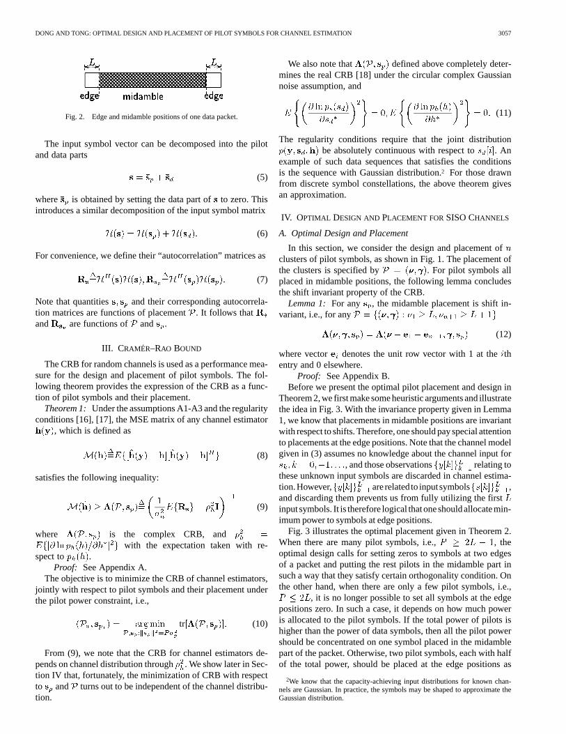
We also define the edge and midamble positions for eachpacket, as shown in Fig. 2. Edge positions are defined as thefirst and last positions in a packet. The rest of the parts withininterval [ , ] are midamble positions.
For a training-based channel estimation, only those parts ofthe observations corresponding to pilot symbols are used. Ifthere is a pilot cluster of length less than , no pilot symbolscorresponding to this cluster can be used for channel estimation.Therefore, it is intuitive that all pilot symbols should be groupedinto a single cluster. This intuition, however, is not valid if allobservations are used for channel estimation. Indeed, the use ofmultiple clusters results in a simpler design of pilot symbols asshown in Section IV and better detection performance (see [1]).
DONG AND TONG: OPTIMAL DESIGN AND PLACEMENT OF PILOT SYMBOLS FOR CHANNEL ESTIMATION 3057
Fig. 2. Edge and midamble positions of one data packet.
The input symbol vector can be decomposed into the pilotand data parts
(5)
where is obtained by setting the data part ofto zero. Thisintroduces a similar decomposition of the input symbol matrix
(6)
For convenience, we define their “autocorrelation” matrices as
(7)
Note that quantities and their corresponding autocorrela-tion matrices are functions of placement. It follows thatand are functions of and .
III. CRAMÉR–RAO BOUND
The CRB for random channels is used as a performance mea-sure for the design and placement of pilot symbols. The fol-lowing theorem provides the expression of the CRB as a func-tion of pilot symbols and their placement.
Theorem 1: Under the assumptions A1-A3 and the regularityconditions [16], [17], the MSE matrix of any channel estimator
, which is defined as
(8)
satisfies the following inequality:
(9)
where is the complex CRB, andwith the expectation taken with re-
spect to .Proof: See Appendix A.
The objective is to minimize the CRB of channel estimators,jointly with respect to pilot symbols and their placement underthe pilot power constraint, i.e.,
tr (10)
From (9), we note that the CRB for channel estimators de-pends on channel distribution through. We show later in Sec-tion IV that, fortunately, the minimization of CRB with respectto and turns out to be independent of the channel distribu-tion.
We also note that defined above completely deter-mines the real CRB [18] under the circular complex Gaussiannoise assumption, and
(11)
The regularity conditions require that the joint distributionbe absolutely continuous with respect to . An
example of such data sequences that satisfies the conditionsis the sequence with Gaussian distribution.2 For those drawnfrom discrete symbol constellations, the above theorem givesan approximation.
IV. OPTIMAL DESIGN AND PLACEMENT FORSISO CHANNELS
A. Optimal Design and Placement
In this section, we consider the design and placement ofclusters of pilot symbols, as shown in Fig. 1. The placement ofthe clusters is specified by . For pilot symbols allplaced in midamble positions, the following lemma concludesthe shift invariant property of the CRB.
Lemma 1: For any , the midamble placement is shift in-variant, i.e., for any
(12)
where vector denotes the unit row vector with 1 at thethentry and 0 elsewhere.
Proof: See Appendix B.Before we present the optimal pilot placement and design in
Theorem 2, we first make some heuristic arguments and illustratethe idea in Fig. 3. With the invariance property given in Lemma1, we know that placements in midamble positions are invariantwith respect to shifts. Therefore, one should pay special attentionto placements at the edge positions. Note that the channel modelgiven in (3) assumes no knowledge about the channel input for
, and those observations relating tothese unknown input symbols are discarded in channel estima-tion.However, are relatedto inputsymbols ,and discarding them prevents us from fully utilizing the firstinputsymbols. It is therefore logical thatoneshouldallocatemin-imum power to symbols at edge positions.
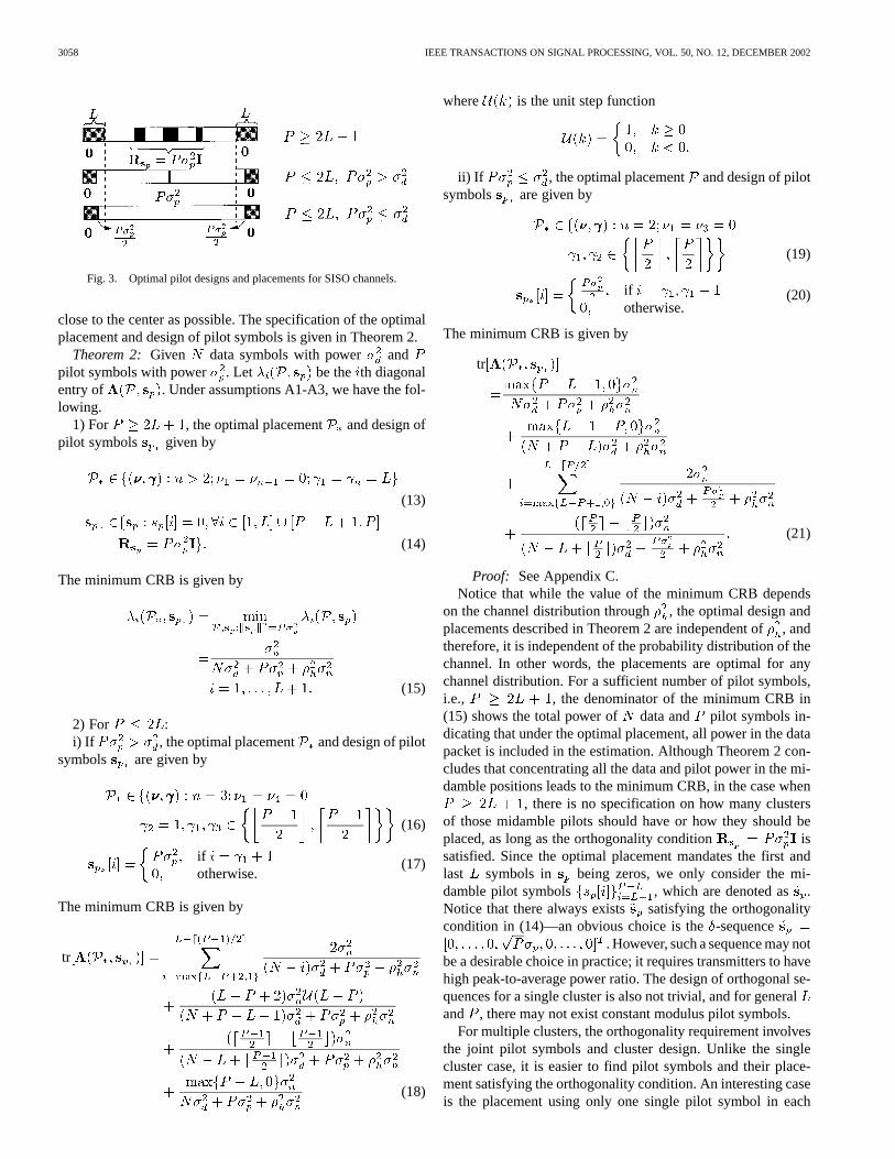
Fig. 3 illustrates the optimal placement given in Theorem 2.When there are many pilot symbols, i.e., , theoptimal design calls for setting zeros to symbols at two edgesof a packet and putting the rest pilots in the midamble part insuch a way that they satisfy certain orthogonality condition. Onthe other hand, when there are only a few pilot symbols, i.e.,
, it is no longer possible to set all symbols at the edgepositions zero. In such a case, it depends on how much poweris allocated to the pilot symbols. If the total power of pilots ishigher than the power of data symbols, then all the pilot powershould be concentrated on one symbol placed in the midamblepart of the packet. Otherwise, two pilot symbols, each with halfof the total power, should be placed at the edge positions as
2We know that the capacity-achieving input distributions for known chan-nels are Gaussian. In practice, the symbols may be shaped to approximate theGaussian distribution.
3058 IEEE TRANSACTIONS ON SIGNAL PROCESSING, VOL. 50, NO. 12, DECEMBER 2002
Fig. 3. Optimal pilot designs and placements for SISO channels.
close to the center as possible. The specification of the optimalplacement and design of pilot symbols is given in Theorem 2.
Theorem 2: Given data symbols with power andpilot symbols with power . Let be the th diagonalentry of . Under assumptions A1-A3, we have the fol-lowing.
1) For , the optimal placement and design ofpilot symbols given by
(13)
(14)
The minimum CRB is given by
(15)
2) For :i) If , the optimal placement and design of pilot
symbols are given by
(16)
ifotherwise.
(17)
The minimum CRB is given by
tr
(18)
where is the unit step function
ii) If , the optimal placement and design of pilotsymbols are given by
(19)
ifotherwise.
(20)
The minimum CRB is given by
tr
(21)
Proof: See Appendix C.Notice that while the value of the minimum CRB depends
on the channel distribution through , the optimal design andplacements described in Theorem 2 are independent of, andtherefore, it is independent of the probability distribution of thechannel. In other words, the placements are optimal for anychannel distribution. For a sufficient number of pilot symbols,i.e., , the denominator of the minimum CRB in(15) shows the total power of data and pilot symbols in-dicating that under the optimal placement, all power in the datapacket is included in the estimation. Although Theorem 2 con-cludes that concentrating all the data and pilot power in the mi-damble positions leads to the minimum CRB, in the case when
, there is no specification on how many clustersof those midamble pilots should have or how they should beplaced, as long as the orthogonality condition issatisfied. Since the optimal placement mandates the first andlast symbols in being zeros, we only consider the mi-damble pilot symbols , which are denoted as .Notice that there always exists satisfying the orthogonalitycondition in (14)—an obvious choice is the-sequence
. However, such a sequence may notbe a desirable choice in practice; it requires transmitters to havehigh peak-to-average power ratio. The design of orthogonal se-quences for a single cluster is also not trivial, and for generaland , there may not exist constant modulus pilot symbols.
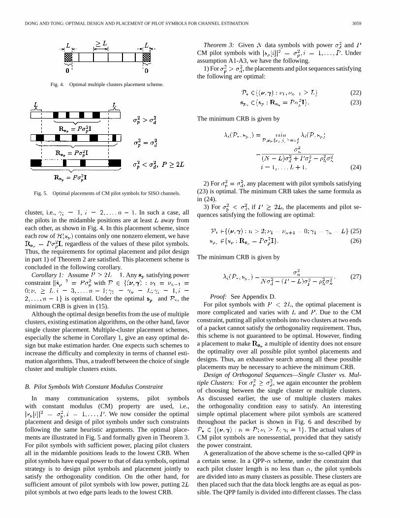
For multiple clusters, the orthogonality requirement involvesthe joint pilot symbols and cluster design. Unlike the singlecluster case, it is easier to find pilot symbols and their place-ment satisfying the orthogonality condition. An interesting caseis the placement using only one single pilot symbol in each
DONG AND TONG: OPTIMAL DESIGN AND PLACEMENT OF PILOT SYMBOLS FOR CHANNEL ESTIMATION 3059
Fig. 4. Optimal multiple clusters placement scheme.
Fig. 5. Optimal placements of CM pilot symbols for SISO channels.
cluster, i.e., , . In such a case, allthe pilots in the midamble positions are at leastaway fromeach other, as shown in Fig. 4. In this placement scheme, sinceeach row of contains only one nonzero element, we have
, regardless of the values of these pilot symbols.Thus, the requirements for optimal placement and pilot designin part 1) of Theorem 2 are satisfied. This placement scheme isconcluded in the following corollary.
Corollary 1: Assume . Any satisfying powerconstraint with
is optimal. Under the optimal and , theminimum CRB is given in (15).
Although the optimal design benefits from the use of multipleclusters, existing estimation algorithms, on the other hand, favorsingle cluster placement. Multiple-cluster placement schemes,especially the scheme in Corollary 1, give an easy optimal de-sign but make estimation harder. One expects such schemes toincrease the difficulty and complexity in terms of channel esti-mation algorithms. Thus, a tradeoff between the choice of singlecluster and multiple clusters exists.
B. Pilot Symbols With Constant Modulus Constraint
In many communication systems, pilot symbolswith constant modulus (CM) property are used, i.e.,
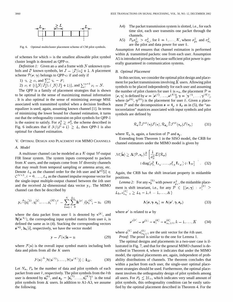
. We now consider the optimalplacement and design of pilot symbols under such constraintsfollowing the same heuristic arguments. The optimal place-ments are illustrated in Fig. 5 and formally given in Theorem 3.For pilot symbols with sufficient power, placing pilot clustersall in the midamble positions leads to the lowest CRB. Whenpilot symbols have equal power to that of data symbols, optimalstrategy is to design pilot symbols and placement jointly tosatisfy the orthogonality condition. On the other hand, forsufficient amount of pilot symbols with low power, putting 2pilot symbols at two edge parts leads to the lowest CRB.
Theorem 3: Given data symbols with power andCM pilot symbols with . Underassumption A1-A3, we have the following.
1) For , the placements and pilot sequences satisfyingthe following are optimal:
(22)
(23)
The minimum CRB is given by
(24)
2) For , any placement with pilot symbols satisfying(23) is optimal. The minimum CRB takes the same formula asin (24).
3) For , if , the placements and pilot se-quences satisfying the following are optimal:
(25)
(26)
The minimum CRB is given by
(27)
Proof: See Appendix D.For pilot symbols with , the optimal placement is
more complicated and varies with and . Due to the CMconstraint, putting all pilot symbols into two clusters at two endsof a packet cannot satisfy the orthogonality requirement. Thus,this scheme is not guaranteed to be optimal. However, findinga placement to make a multiple of identity does not ensurethe optimality over all possible pilot symbol placements anddesigns. Thus, an exhaustive search among all these possibleplacements may be necessary to achieve the minimum CRB.
Design of Orthogonal Sequences—Single Cluster vs. Mul-tiple Clusters: For , we again encounter the problemof choosing between the single cluster or multiple clusters.As discussed earlier, the use of multiple clusters makesthe orthogonality condition easy to satisfy. An interestingsimple optimal placement where pilot symbols are scatteredthroughout the packet is shown in Fig. 6 and described by
. The actual values ofCM pilot symbols are nonessential, provided that they satisfythe power constraint.
A generalization of the above scheme is the so-called QPP ina certain sense. In a QPP-scheme, under the constraint thateach pilot cluster length is no less than, the pilot symbolsare divided into as many clusters as possible. These clusters arethen placed such that the data block lengths are as equal as pos-sible. The QPP family is divided into different classes. The class
3060 IEEE TRANSACTIONS ON SIGNAL PROCESSING, VOL. 50, NO. 12, DECEMBER 2002
Fig. 6. Optimal multicluster placement scheme of CM pilot symbols.
of schemes for which is the smallest allowable pilot symbolcluster length is denoted as QPP-.
Definition 1: Given an and a frame with unknown sym-bols and known symbols, let . A placementscheme belongs to QPP- if and only if
1) , and ;2) , and .The QPP is a family of placement strategies that is shown
to be optimal in the sense of maximizing mutual information. It is also optimal in the sense of minimizing average MSEassociated with transmitted symbol when a decision feedbackequalizer is used, again, assuming known channel [1]. In termsof minimizing the lower bound for channel estimation, it turnsout that the orthogonality constraint on pilot symbols for QPP-1is the easiest to satisfy. For , the scheme described inFig. 6 indicates that if , then QPP-1 is alsooptimal for channel estimation.
V. OPTIMAL DESIGN AND PLACEMENT FORMIMO CHANNELS
A. Model
A multiuser channel can be modeled as a-input -outputFIR linear system. The system inputs correspond to packetsfrom users, and the outputs come fromdiversity channelsthat may result from temporal sampling or antenna array, etc.Denote as the channel order for theth user and
as the channel impulse response vector forthe single-input multiple-output channel between theth userand the received -dimensional data vector . The MIMOchannel can then be described by
(28)
where the data packet from useris denoted by , and, the correspoding input symbol matrix from user, is
defined the same as in (4). Stacking the corresponding vectors, , respectively, we have the vector model
(29)
where is the overall input symbol matrix including bothdata and pilots from all the users
(30)
Let , be the number of data and pilot symbols of eachpacket from user, respectively. The pilot symbols from thethuser is denoted by , and is the totalpilot symbols from users. In addition to A1-A3, we assumethe following.
A4) The packet transmission system is slotted, i.e., for eachtime slot, each user transmits one packet through thechannels.
A5) , for , where andare the pilot and data power for user.
Assumption A4 ensures that channel estimation is performedwithin transmitted packets: one from each user. AssumptionA5 is introduced primarily because sufficient pilot power is gen-erally guaranteed in communication systems.
B. Optimal Placement
In this section, we consider the optimal pilot design and place-ment for packet transmissions involvingusers. Allowing pilotsymbols to be placed independently for each user and assumingthe number of pilot clusters for useris , the placement
is defined by , ,where ( , ) is the placement for user. Given a place-ment and the decomposition as in (5), the “au-tocorrelation” matrices associated with input symbols and pilotsymbols are defined by
(31)
where is, again, a function of and .Extending from Theorem 1 in the SISO model, the CRB for
channel estimators under the MIMO model is given by
diag (32)
Again, the CRB has the shift invariant property in midamblepositions.
Lemma 2: For any with power , the midamble place-
ment is shift invariant, i.e., for any
(33)
where is related to by
(34)
where and are the unit vector for theth user.Proof: The proof is similar to the one for Lemma 1.The optimal designs and placements in a two-user case is il-
lustrated in Fig. 7, and that for the general MIMO channel is de-scribed in Theorem 4, where it indicates that under the MIMOmodel, the optimal placements are, again, independent of prob-ability distributions of channels. The theorem concludes thatwithin a packet from each user, the single-user optimal place-ment strategies should be used. Furthermore, the optimal place-ment involves the orthogonality design of pilot symbols amongall users. For , which indicates very small amount ofpilot symbols, this orthogonality condition can be easily satis-fied by the optimal placement described in Theorem 4. For the

DONG AND TONG: OPTIMAL DESIGN AND PLACEMENT OF PILOT SYMBOLS FOR CHANNEL ESTIMATION 3061
Fig. 7. Optimal placements of pilot symbols for the MIMO channel.
other case when , which is usually satisfied, theoptimal design is nontrivial in general and is discussed in Sec-tion V-C
Theorem 4: Given data symbols with power andpilot symbols with power from the th user, .
Let be the CRB for theth channel coefficient ofuser . Under assumptions A1-A4, we have the following.
1) For , , the optimal placementand design of pilot symbols are given by
(35)
diag
(36)
The minimum CRB is given by
(37)
2) For , , under assumption A5, theoptimal placement and design of pilot symbols are givenby
(38)
ifotherwise
(39)
The minimum CRB is given by
tr
tr
(40)
where is the unit step function.Proof: See Appendix E.
C. Multiuser Placement Strategies
In this section, we only consider the case when .As discussed in Section IV, it is difficult to design orthogonalsequences for those pilot symbols in the midamble positionsif they are grouped in a single pilot cluster. Multiple clustersshould be considered. Then, the next question follows: Shouldwe align pilot clusters from each user at the same position? The-orem 4 indicates that as long as the pilots between users areorthogonal, the placement is still optimal. However, by doingthis, we should consider all pilot sequences jointly, whichincreases the difficulty of the sequence design. An easy wayto simplify the problem is to place the pilot clusters staggeredamong users. As an example shown in Fig. 8, two users arepresent in the system. Clusters from users 1 and 2 are offset toeach other so that in (31) is block diagonal. The orthogo-nality condition between users are automatically satisfied. Notethat the pilot sequence design can now be done independently.Moreover, smaller cluster size also simplifies the pilot design.
Furthermore, the easiest way to satisfy the orthogonality con-dition, perhaps, is the scheme described in Fig. 4 extended forthe multiple-user case as illustrated in Fig. 9. The lowest CRBscan be obtained if pilot symbols in the midamble positions arescattered in such a way that they are at least apart.By this way, the actual values of pilot symbols are nonessentialas long as they satisfy the power constraint.
D. Pilot Symbols With Constant Modulus Constraint
Consider all users using CM pilot symbols, i.e.,, for all . The optimal placements are il-
lustrated in a two-user case in Fig. 10 and described in thefollowing theorem.
Theorem 5: Assume CM pilot symbols. Under assumptionA1-A4, we have the following.

3062 IEEE TRANSACTIONS ON SIGNAL PROCESSING, VOL. 50, NO. 12, DECEMBER 2002
Fig. 8. Optimal placement for two-user case.
Fig. 9. Optimal placement for three-user case.
1) For , the optimal placementand design of pilot symbols are given by
(41)
diag
(42)
The minimum CRB is given by
(43)
2) For , any placement with pilotsymbols satisfying (42) is optimal. The minimum CRB takesthe same formula in (43).
Proof: The proof is similar to the one in Theorem 3.For , the optimal placement should satisfy the
single-user optimal placement requirement and, at the sametime, satisfies cross-user orthogonality condition. However,such pilot sequences satisfying both conditions might not exist.Thus, finding an optimal placement scheme may follow anexhaustive search among all possible placements. The resultingoptimal placement then depends on each specific situation.
For sufficient pilot power, the easiest scheme perhaps isQPP-1 scheme extended for multiple users as illustrated inFig. 11, which can be summarized by the following corollary.
Corollary 2: For any satisfying ,, the placement is optimal if
satisfies
1) ;
2).
Although the extended QPP-1 scheme is the easiest to satisfythe orthogonality condition, it requires each user’s packet lengthto be sufficiently long to allow pilot symbols to scatter out. Onthe other hand, the longer pilot cluster length, the shorter packet
Fig. 10. Optimal placements of CM pilot symbols for the MIMO channel.
Fig. 11. Optimal QPP-1 placement for three users.
size is required; this is especially tractable for short packet com-munication scenarios. Therefore, there again exists a tradeoffbetween the choice of short and long pilot clusters.
VI. PLACEMENT FORCHANNELS WITH CORRELATEDTAPS
In the previous sections, we discussed the design andplacement of pilot symbols for random channels with tapsbeing i.i.d. In this section, we look into a more general casewhere channel taps are correlated. The SISO channel modelis considered. Specifically, the channel is the combination ofthe pulse shaping filter and propagation channel. Althoughthe propagation channel appears random changes from packetto packet, due to the pulse shaping filter, channel taps arecorrelated to each other in general. Thus, channelappearsrandom but is restricted within a certain subspace. Therefore,assuming A1 and A3, we relax A2 to the following assumption.
A2’) The channel can be represented by
(44)
where has orthonormalcolumns, and vector consists of i.i.d. zero mean randomvariables with pdf and variance .
When , channel taps are correlated with covariance. In the special case when ,
assumption A2’ reduces to A2.
A. CRB
The complex CRB for transformations of deterministicparameters was derived in [19]. For linear transformation ofrandom parameters, the complex CRB becomes
(45)

DONG AND TONG: OPTIMAL DESIGN AND PLACEMENT OF PILOT SYMBOLS FOR CHANNEL ESTIMATION 3063
where is a random parameter vector, and ; is theCRB for . Given the channel model in (44), the complex CRBfor channel estimators is then derived as
(46)
B. Placement
It is not hard to see that for general random channels, Lemma1 still holds. Our objective is to find and among all or-thogonal pilot sequences such that
tr (47)
Theorem 6: Assume . Among all orthogonalpilot sequences, i.e., { diagonal}, the optimal placementis given by
(48)
(49)
The minimum CRB is given by
tr (50)
Proof: See Appendix F.For pilot symbols with CM property, following Theorem 6
and using the similar proof, we see that when , amongall orthogonal pilot sequences, placing all pilot symbols in themidamble positions is optimal:
(51)
and the minimum CRB is given by
tr (52)
When , is invariant under among orthog-onal sequences, i.e., different placements result in equal perfor-mance.
All the above show that the optimal placement strategy forchannels with i.i.d. taps is also optimal, among all orthogonalpilot sequences, for channels with correlated taps. Note that ourresults of optimal placements are confined in searching amongall possible orthogonal pilot sequences. It does not imply thatthis placement minimizes tr for all choices of pilotsequences. Indeed, in general, the placement that gives the min-imum tr depends heavily on and each specific re-alization of pilot sequences.
VII. N UMERICAL RESULTS
A. Placement Schemes in Single User Case
We first compared the CRBs of channel estimators under op-timal and nonoptimal pilot design and placement schemes inthe SISO model. Channel order was . We assumed that
(a)
(b)
Fig. 12. (a) CRBs of different placements versus percentage of pilot symbolsat SNR= 10 dB. (b) CRBs versus different placements under low pilot powerat SNR= 20 dB.
channel taps are i.i.d. complex Gaussian with zero mean andvariance . The data packet length was100. Data and pilot powers were and , respec-tively. Four placement schemes were considered:
1) the optimal placement allowing power allocation;2) the optimal placement for pilot symbols with CM con-
straint;3) a single cluster with CM pilot symbols used in 2) placed
in the middle of the packet and the pilot sequence violatedthe orthogonality requirement;
4) the same single cluster placed at one end of packet.
In the first optimal scheme, we used the placement describedin Corollary 1. For the second one with CM constraint, QPP-3placement was used with each pilot cluster being [, ,
]. Fig. 12(a) shows the traces of CRBs of these fourschemes under increasing percentage of pilot symbols perpacket at SNR dB. We observe that the gain of the
3064 IEEE TRANSACTIONS ON SIGNAL PROCESSING, VOL. 50, NO. 12, DECEMBER 2002
Fig. 13. CRBs of different placement schemes in a two-user case.
optimal scheme increases with increasing percentage of pilotsymbols.
Finally, for pilot symbols with CM constraint, we give an ex-ample when pilot symbols with low power . Twoschemes were compared: 1) optimal placement for pilot sym-bols with CM constraint and 2) single cluster with the same pilotsequence placed in the middle of the packet. Fig. 12(b) plots theCRBs versus the percentage of pilot symbols at dB.We can see that in this case, putting pilot symbols at two endsof the frame resulted in lower CRBs. Notice that because thetotal power from data and pilot symbols decreases with the per-centage of pilot symbols increasing, the corresponding CRBsincreases.
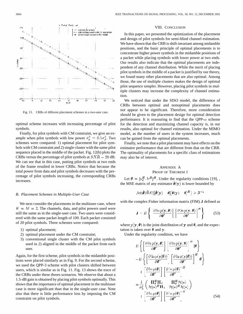
B. Placement Schemes in Multiple-User Case
We next consider the placements in the multiuser case, where. The channels, data, and pilot powers used were
still the same as in the single-user case. Two users were consid-ered with the same packet length of 100. Each packet consistedof 20 pilot symbols. Three schemes were compared:
1) optimal placement;2) optimal placement under the CM constraint;3) conventional single cluster with the CM pilot symbols
used in 2) aligned in the middle of the packet from eachuser.
Again, for the first scheme, pilot symbols in the midamble posi-tions were placed similarly as in Fig. 9. For the second scheme,we used the QPP-3 scheme with pilot clusters shifted betweenusers, which is similar as in Fig. 11. Fig. 13 shows the trace ofthe CRBs under these threes scenarios. We observe that about a1.5-dB gain is obtained by placing pilot symbols optimally. Thisshows that the importance of optimal placement in the multiusercase is more significant than that in the single-user case. Notealso that there is little performance loss by imposing the CMconstraint on pilot symbols.
VIII. C ONCLUSION
In this paper, we presented the optimization of the placementand design of pilot symbols for semi-blind channel estimation.We have shown that the CRB is shift-invariant among midamblepositions, and the basic principle of optimal placements is toconcentrate higher power symbols in the midamble positions ofa packet while placing symbols with lower power at two ends.Our results also indicate that the optimal placements are inde-pendent of any channel distribution. While the merit of placingpilot symbols in the middle of a packet is justified by our theory,we found many other placements that are also optimal. Amongthose, the use of multiple clusters makes the design of optimalpilot sequence simpler. However, placing pilot symbols in mul-tiple clusters may increase the complexity of channel estima-tion.
We noticed that under the SISO model, the difference ofCRBs between optimal and nonoptimal placements doesnot appear to be significant. Therefore, more considerationshould be given to the placement design for optimal detectionperformance. It is reassuring to find that the QPP-schemefor the detection and maximizing channel capacity is, in ourresults, also optimal for channel estimation. Under the MIMOmodel, as the number of users in the system increases, muchcan be gained from the optimal placements.
Finally, we note that a pilot placement may have effects on theestimator performance that are different from that on the CRB.The optimality of placements for a specific class of estimationsmay also be of interest.
APPENDIX APROOF OFTHEOREM 1
Let . Under the regularity conditions [19], ,the MSE matrix of any estimator is lower bounded by
with the complex Fisher information matrix (FIM)defined as
(53)
where is the joint distribution of and , and the expec-tation is taken over and .
Under the regularity condition, we have
(54)
DONG AND TONG: OPTIMAL DESIGN AND PLACEMENT OF PILOT SYMBOLS FOR CHANNEL ESTIMATION 3065
where is obtained from by deleting columns corre-sponding to pilot symbols.
By assumptions of and in A1-A3, we have
(55)
Now, we can obtain the expression of the FIM
(56)
Under the regularity conditions and assumptions A1-A3, since, where and are joint pdf of
and , respectively, the second term in (56) becomes
(57)
where , are defined as
(58)
where the expectation is taken with respect to and ,respectively.
Therefore, the complex FIM is
(59)
Consequently
Notice that the FIM for is block diagonal, and CRBs for thechannel and data symbols are decoupled. The complex CRB forthe MSE of channel estimators is then given by
(60)
APPENDIX BPROOF OFLEMMA 1
When , all pilot symbols are placed in themidamble positions. For the-cluster case, defined in (7)
is a function of and , which is denoted as . Sinceis i.i.d. with zero mean, we have
(61)
Substituting the above into (9), the CRB becomes
(62)
Notice that ( ) is corresponding to shifting theclusters to the right by 1 without changing their relative dis-
tances. From the structure of , it is not hard to see thatwhen ,
(63)
This means, for fixed and [ ], is invariantfor different and , and we have
(64)
Therefore, is invariant under shifting of the clus-ters among the midamble positions.
APPENDIX CPROOF OFTHEOREM 2
From (9), we know that
(65)
where is given by
where and an indicator function, definedby if pilot symbol appears in theth columnof and otherwise. Note that
. Denoting as the total number of pilotsymbols in the th column of , we have
(66)
Define
(67)
Case 1— : Let , be the total number of pilotsymbols in the two edge parts belonging to the beginning and

3066 IEEE TRANSACTIONS ON SIGNAL PROCESSING, VOL. 50, NO. 12, DECEMBER 2002
end of a packet, respectively. Note that . We nowbound as follows:
(68)
The equalities hold for all if and only if . There-fore, the minimum number of pilot symbols in each column is
.From (66), we have
(69)
with equality if and only if and, i.e., the total power is allocated on the ( ) pilot
symbols that are in the midamble positions. From Lemma 1, wenote that any midamble placements are shift invariant. Thus, theplacement described in Theorem 2.1 maximizes andminimizes in (67)
(70)
By the Cauchy–Schwartz inequality,3 , is lowerbounded by
(71)
and
tr (72)
where the equalities hold if and only if . Thus, wehave
(73)
and
tr
(74)
where the equalities hold under the optimal placement describedin Theorem 2.1.
3The Cauchy-Schwartz inequality is that for any positive definite matrixA,(A ) � 1=A , with equality iffA is a diagonal matrix.
Case 2— : i) : We prove that the place-ment described in part 2) i) of Theorem 2 minimizes .
a) We first show that for any fixed placement, allocating totalpilot energy on those symbols in the midamble positions, de-creases .
From (67), we have
(75)
with equality if and only if and ,i.e., there exist pilot symbols in the midamble positions, andtheir total power is , whereas the power of those at the edgeparts are all zeros. Since , for any fixed (fixedplacement), (75) gives the minimum .
b) If (75) is satisfied, the only variable in is .Notice that placing pilot symbols at two ends decreasesfor some , thus decreasing in (75). Therefore, tominimize (75), all ( ) pilot symbols should be placed atthe two ends. In other words, assign to a single pilot in themidamble position, and split the rest ( ) pilot symbols intotwo clusters at two ends of a packet. Furthermore, among allpossible ways of splitting these ( ) symbols, dividing themevenly ( , ) at two ends minimizes
4 . Thus the placement described in the Theoremminimizes .
We now calculate . Under the optimal place-ment, for the th column is given by (76), shown at thebottom of the page. Substituting into (75), we obtain theminimum as in (77), shown at the bottom of the nextpage. Combining the common terms, we obtain (18). Since, bythis placement, , following the same argument asin Case 1, we have
tr (78)
ii) : In part i), under the optimal placement
(79)
where is defined in (76). In the case when ,can be further reduced by removing ( ) from
4This is because the following inequality:(1=a) + (1=(a+ b)) �
(1=(a+ b=2)) + (1=(a+ b=2)), wherea; b > 0.
(76)
DONG AND TONG: OPTIMAL DESIGN AND PLACEMENT OF PILOT SYMBOLS FOR CHANNEL ESTIMATION 3067
the denominator and reducing the quantity for some . It isnot hard to see that under the optimal placement in parti), which is shown in (79), monotonically decreases by movingthe pilot symbol with power from the midamble part to theposition next to the pilot, which is in the edge part and is closestto the center. Therefore, we have
(80)
Thus, all pilot symbols should be placed at two ends while allo-cating the total pilot power on the two pilot symbols closest tothe center. Finally, by the same argument in part i), allocatingpower evenly ( ) to each pilot closest to the center min-imizes . Thus, the placement described in part 2) ii)of Theorem 2.2 is optimal. Under this placement, we calculate
as in (81), shown at the bottom of thepage, and the minimum is as in (82), also shown atthe bottom of the page. Rearranging the index, we obtain (21).Since is diagonal under this placement, we have
tr
APPENDIX DPROOF OFTHEOREM 3
Case 1— : In this case, since , (65) becomes
(83)
(84)
with equality if and only if for all . In otherwords, all the pilot symbols should be placed in the midamblepositions
(85)
Following (71), we have
(86)
with equality when the conditions in (22) and (23) are satisfied.Case 2— : When pilot and data powers are equal,
we see that (83) becomes
(87)
(77)
ifif
(81)
(82)
3068 IEEE TRANSACTIONS ON SIGNAL PROCESSING, VOL. 50, NO. 12, DECEMBER 2002
Thus, different placements do not affect , and wehave
with equality if and only if
Case 3— and : From (68), is lowerbounded by . Then, in this case,in (83) satisfies
(88)
Note that the equality holds when , i.e., all the edgepositions are filled with pilot symbols. Thus
with equality if and only if
APPENDIX EPROOF OFTHEOREM 4
Given in (32), the CRB under the MIMO model is
diag
Again, as can be decomposed into and , we have
...
(89)
where and are the autocorrelation matrices for theth user defined under the SISO model.From the above equation, we can see that the expression of the
th diagonal block (corresponding to theth user) is the sameas that in the SISO case. Thus, we have
(90)
Define (91), shown at the bottom of the page.Case 1— : Notice that (90) only involves
from the th user; thus, to maximize ,
the placement for the packet from usershould be the same asdescribed in the SISO case. Therefore, we have
(92)
Using the Cauchy–Schwartz inequality again, we have
(93)
with equality if and only if
diag
Notice the that optimal design and placement involves pilotsymbols among all users. This cross-user effect on placementcan be seen in , where the off-diagonal th block is thecross “correlation” matrix between userand .
Case 2— : We do not give a detailed proof inthis case since it can be similarly derived from previous results.Similarly, as in Case 1, we see that by Theorem 2, the placementdescribed in this case minimizes in (91). Therefore, tosatisfy
tr
we require
diag
APPENDIX FPROOF OFTHEOREM 6
From the CRB for channel estimators given in (46),we have
tr tr
tr
(94)
where is upper bounded by
(95)
(91)
DONG AND TONG: OPTIMAL DESIGN AND PLACEMENT OF PILOT SYMBOLS FOR CHANNEL ESTIMATION 3069
with the equality iff the placement described in (48) and (49) issatisfied, where the total pilot power is concentrated on thosepilots in the midamble positions.
Note that by definition, for any orthogonal pilot sequence,is diagonal. Consequently, is a diagonal matrix.
Therefore, we have
tr
(96)
where equalities hold when .Thus, minimizing tr is equivalent to
subject to
(97)
Hence, tr is minimized by making allequal
and, at the same time, satisfying
Therefore, the placement described in the Theorem gives theminimum CRB shown in (50).
REFERENCES
[1] S. Adireddy and L. Tong, “Detection with embedded known symbols:Optimal symbol placement and equalization,” inProc. ICASSP Conf.,vol. 5, Istanbul, Turkey, June 2000, pp. 2541–2544.
[2] S. Adireddy, L. Tong, and H. Viswanathan, “Optimsl placement oftraining for frequency selective block-fading channels,”IEEE Trans.Inform Theory, vol. 48, pp. 2338–2353, Aug. 2002.
[3] B. Hassibi and B. Hochwald, “How much training is needed in mul-tiple-antenna wireless links,”IEEE Trans. Inform. Theory, Aug. 2000,submitted for publication.
[4] S. Ohno and G. B. Giannakis, “Optimal training and redundant pre-coding for block transmissions with application to wireless OFDM,”IEEE Trans. Commun., Nov. 2000, submitted for publication.
[5] R. Heimiller, “Phase shift pulse codes with good periodic correlationproperties,”IRE Trans. Inform. Theory, vol. IT-7, pp. 254–257, Oct.1961.
[6] B. Popovic, “Generalized chirp-like polyphase sequences with op-timum correlation properties,”IEEE Trans. Inform. Theory, vol. 38, pp.1406–1409, July 1992.
[7] J. C. L. Ng, K. B. Letaief, and R. D. Murch, “Complex optimal sequenceswith constant magnitude for fast channel estimation initialization,”IEEETrans. Commun., vol. 46, pp. 305–308, Mar. 1998.
[8] C. Tellambura, M. G. Parker, Y. J. Guo, S. J. Shepherd, and S. K. Barton,“Optimal sequences for channel estimation using discrete Fourier trans-form techniques,”IEEE Trans. Commun., vol. 47, pp. 230–238, Feb.1999.
[9] R. Negi and J. Cioffi, “Pilot tone selection for channel estimation ina mobile OFDM system,”IEEE Tran. Consum. Electron., vol. 44, pp.1122–1128, Aug. 1998.
[10] F. Ling, “Optimal reception, performance bound, and cutoff rate anal-ysis of references-assisted coherent CDMA communications with ap-plications,”IEEE Trans. Commun., vol. 47, pp. 1583–1592, Oct. 1999.
[11] S. Adireddy and L. Tong, “Optimal placement of known symbols fornonergodic broadcast channels,”IEEE Trans. Inform. Theory, submittedfor publication.
[12] B. M. Sadler, R. J. Kozick, and T. Moore, “Constrained CRB’s forchannel and signal estimation of mimo systems,” inProc. 35st Annu.Conf. Inform. Sci. Syst., Baltimore, MD, Mar. 2001.
[13] J. D. Gorman and A. O. Hero, “Lower bounds for parametric estimationwith constraints,”IEEE Trans. Inform. Theory, vol. 36, pp. 1285–1301,Nov. 1990.
[14] E. de Carvahlo and D. T. M. Slock, “Semi-blind methods for FIRmultichannel estimation,” inSignal Processing Advances in Wirelessand Mobile Communications, Giannakis, Hua, Stoica, and Tong,Eds. Englewood Cliffs, NJ: Prentice-Hall, 2000, pp. 211–254.
[15] C. Budianu and L. Tong, “Channel estimation for space-time orthogonalblock code,”IEEE Trans. Signal Processing, vol. 50, pp. 2515–2528,Oct. 2002.
[16] H. L. Van Trees,Detection, Estimation and Modulation Theory. NewYork: Wiley, 1968, vol. 1.
[17] E. Weinstein and A. Weiss, “A general class of lower bounds in param-eter estimation,”IEEE Trans. Inform. Theory, vol. 34, pp. 338–342, Mar.1988.
[18] E. de Carvalho and D. T. M. Slock, “Cramér-Rao bounds for semi blind,blind and training sequence based channel estimation,”Proc. First IEEESignal Process. Workshop Signal Process. Adv. Wireless Commun., vol.1, pp. 129–132, Apr. 1997.
[19] M. Dong and L. Tong, “Channel estimation and equalization withblock interleavers,”Proc. Third IEEE Signal Process. Workshop SignalProcess. Adv. Wireless Commun., Mar. 2001.
Min Dong (S’00) received the B.S. degree from theDepartment of Automation, Tsinghua University,Beijing, China, in 1998. She is now pursuingthe Ph.D. degree at the School of Electrical andComputer Engineering, Cornell University, Ithaca,NY. Her research interests include statistical signalprocessing, wireless communications, and coomuu-nication networks.
Lang Tong (S’87–M’91–SM’01) received the B.E.degree from Tsinghua University, Beijing, China, in1985 and the M.S. and Ph.D. degrees in electrical en-gineering in 1987 and 1990, respectively, from theUniversity of Notre Dame, Notre Dame, IN.
After being a Postdoctoral Research Associatewith the Information Systems Laboratory, StanfordUniversity, Stanford, CA, he joined the Departmentof Electrical and Computer Engineering, WestVirginia University, Morgantown, and was also withthe University of Connecticut, Storrs. Since the
Fall of 1998, he has been with the School of Electrical Engineering, CornellUniversity, Ithaca, NY, where he is an Associate Professor. He also held aVisiting Assistant Professor position at Stanford University in the Summerof 1992. His research interests include statistical signal processing, wirelesscommunications, and system theory.
Dr. Tong received the Young Investigator Award from the Office of NavalResearch in 1996 and the Outstanding Young Author Award from the IEEECircuits and Systems Society.