Embed Size (px)
Citation preview

2-wire / Guided Radar (TDR) Level Meter
Safety manualSafety manualSafety manualSafety manual
OPTIFLEX 2200 COPTIFLEX 2200 COPTIFLEX 2200 COPTIFLEX 2200 C Supplementary instructions Supplementary instructions Supplementary instructions Supplementary instructions
© KROHNE 01/2013 - 4000738603 - AD SIL OPTIFLEX 2200 R03 en

CONTENTS
2 www.krohne.com 01/2013 - 4000738603 - AD SIL OPTIFLEX 2200 R03 en
OPTIFLEX 2200 C
1 Introduction 4
1.1 Scope of the document..................................................................................................... 41.2 Revision history ................................................................................................................ 41.3 Device description ............................................................................................................ 51.4 Related documentation .................................................................................................... 51.5 Terms and definitions....................................................................................................... 6
2 System description 7
2.1 Peripheral equipment ...................................................................................................... 72.2 Software for use with the device ...................................................................................... 7
3 Installation 8
4 Electrical connection 9
5 Start-up 10
5.1 General notes ................................................................................................................. 105.2 Device parameters ......................................................................................................... 10
6 Specification of safety function 11
6.1 Preliminary requirements.............................................................................................. 116.2 Safety function definition................................................................................................ 11
6.2.1 General notes........................................................................................................................ 116.2.2 Limits of application.............................................................................................................. 116.2.3 Safety function characteristics ............................................................................................. 12
7 Operation 13
7.1 Conditions of use ............................................................................................................ 137.2 Failure state ................................................................................................................... 137.3 Operation mode .............................................................................................................. 147.4 Error conditions.............................................................................................................. 157.5 User parameters ............................................................................................................ 16
7.5.1 Limits for supervisor menu functions related to probe configuration ................................ 167.5.2 Limits for supervisor menu functions related to device configuration ............................... 17
8 Service 19
8.1 Periodic maintenance..................................................................................................... 198.2 Keep the device clean..................................................................................................... 198.3 Availability of services .................................................................................................... 198.4 Proof tests ...................................................................................................................... 19
CONTENTS
3www.krohne.com01/2013 - 4000738603 - AD SIL OPTIFLEX 2200 R03 en
OPTIFLEX 2200 C
8.5 Calibration procedure .................................................................................................... 228.5.1 General notes........................................................................................................................ 228.5.2 Current output check............................................................................................................ 238.5.3 Measuring range check (in process conditions) .................................................................. 24
8.6 Troubleshooting.............................................................................................................. 258.7 Returning the device to the manufacturer..................................................................... 25
8.7.1 General information.............................................................................................................. 258.7.2 Form (for copying) to accompany a returned device............................................................ 26
9 Technical data 27
9.1 General notes ................................................................................................................. 279.2 Assumptions ................................................................................................................... 279.3 Characteristics for the device safety function ............................................................... 289.4 SIL-specific technical data ............................................................................................. 299.5 Support for SIL-approved devices.................................................................................. 30
10 Appendix 31
10.1 Start-up report ............................................................................................................. 3110.2 Proof test report form (for copying) ............................................................................. 32
11 Notes 33

1 INTRODUCTION
4
OPTIFLEX 2200 C
www.krohne.com 01/2013 - 4000738603 - AD SIL OPTIFLEX 2200 R03 en
1.1 Scope of the document
This document supplies functional safety data about the device. This data agrees with the IEC 61508 standard.
1.2 Revision history
WARNING!The data in this supplement only contains the data applicable to the SIL approval. The technical data for the standard version in the handbook (document [N1]) shall be valid in its current version, provided that it is not rendered invalid or replaced by this supplement.
INFORMATION!Installation, commissioning and maintenance may only be carried out by approved personnel.
Edition Date Description
1 June 1, 2012 First issue.
2 June 13, 2012 Correction of characteristics for the device safety function.
3 January 31, 2013 New edition (2010) of the international standard IEC 61508.

INTRODUCTION 1
5
OPTIFLEX 2200 C
www.krohne.com01/2013 - 4000738603 - AD SIL OPTIFLEX 2200 R03 en
1.3 Device description
This device is a 2-wire level transmitter that uses TDR (Time Domain Reflectometry) / Guided Radar technology. It measures the distance of liquids, liquid gases, pastes, powders, slurries and granular products.
Measurements are given through a 4...20 mA current output and can be displayed via a DTM (device type manager) for remote communication or an integrated display screen with wizard-driven set-up and online help functions. Only the 4...20 mA current output is used as the safety function.
When the device detects a measurement error, it supplies an output current less than 3.6 mA. Although the device can be set to a high error value (≥ 21 mA), some hardware failures can cause the device to give a low error value (≤ 3.6 mA). For more data, refer to Limits for supervisor menu functions related to device configuration on page 17 (2.4.2 RANGE I).
Refer also to "Device description" in the handbook (document [N1]).
1.4 Related documentation
INFORMATION!The manufacturer designed and developed the device for safety integrity level (SIL) 2.Data for the SIL approval is not taken from field experience (i.e. it is not “proven in use”) because this method can give unrealistic data if assumptions are too optimistic.
[N1] OPTIFLEX 2200 Handbook
[N2] IEC 61508-1 to 7:2010 Functional safety of electrical / electronic / programmable electronic safety-related systems
[N3] NAMUR Recommendation NE 043 Standardization of the Signal Level for the Failure Information of Digital Transmitters
[N4] NAMUR Recommendation NE 053 Software of Field Devices and Signal Processing Devices with Digital Electronics
[N5] OPTIFLEX 2200 Supplementary Instructions for ATEX applications

1 INTRODUCTION
6
OPTIFLEX 2200 C
www.krohne.com 01/2013 - 4000738603 - AD SIL OPTIFLEX 2200 R03 en
1.5 Terms and definitions
DCD Diagnostic Coverage of dangerous failures
Firmware Software embedded in the device.
FIT Failure In Time (1×10⁻⁹ failures per hour)
FMEDA Failure Modes, Effects and Diagnostics Analysis
HFT Hardware Fault Tolerance
High demand or continuous mode
Where the frequency of demands for operation made on a safety-related system is greater than one time per year
I/O Input / output
λDD Rate for dangerous detected failure
λDU Rate for dangerous undetected failure
λSD Rate for safe detected failure
λSU Rate for safe undetected failure
Low demand mode Where the frequency of demands for operation made on a safety-related system is no greater than one time per year
MTBF Mean Time Between Failures
MTTF Mean Time To Failure
MTTR Mean Time To Recovery
PFDAVG Average Probability of Failure on Demand
PFH Probability of a dangerous Failure per Hour
SFF Safe Failure Fraction
SIL Safety Integrity Level
SIS Safety Integrated System
TDR Time Domain Reflectometry. The measuring principle. For more data, refer to “Technical Data” in the handbook (document [N1]).
TBF Tank bottom following. A device measurement mode. For more data, refer to “Technical Data” in the handbook (document [N1]).
Type A system "Non-complex" system (all failure modes are well defined). For more data, refer to subsection 7.4.3.1.2 of IEC 61508-2.
Type B system "Complex" system (all failure modes are not well defined). For more data, refer to subsection 7.4.3.1.2 of IEC 61508-2.
T[Proof] Proof Test Interval
T[Repair] Time to Repair
T[Test] Internal Diagnostics Test Interval
1oo1 1 out of 1 channel architecture (single architecture performs the safety function)
1oo1D 1 out of 1 channel architecture with diagnostics
SYSTEM DESCRIPTION 2
7
OPTIFLEX 2200 C
www.krohne.com01/2013 - 4000738603 - AD SIL OPTIFLEX 2200 R03 en
2.1 Peripheral equipment
You can use the device with the equipment that follows:• A logic solver that can read 4...20 mA current input and low error alarm signals• A PC or workstation (this is used only to change parameters)
• A HART® Handheld Controller (this is used only to change parameters)
For more data, refer to "Start-up" in the handbook (document [N1]).
2.2 Software for use with the device
You can change device parameters with the software that follows:• PACTware™• AMS™ Device Manager
For more data, refer to "Start-up" in the handbook (document [N1]).

3 INSTALLATION
8
OPTIFLEX 2200 C
www.krohne.com 01/2013 - 4000738603 - AD SIL OPTIFLEX 2200 R03 en
If the device was delivered without a probe, then calibrate the device to make sure that the safety function operates correctly. This maintenance task must be done and recorded by approved personnel. For more data, refer to Calibration procedure on page 22.
For more data, refer to "Installation" in the handbook (document [N1]).
WARNING!If the device is to agree with the requirements for functional safety given in IEC 61508, you must obey the installation instructions given in the handbook (document [N1]). The device must be installed by approved personnel.

ELECTRICAL CONNECTION 4
9
OPTIFLEX 2200 C
www.krohne.com01/2013 - 4000738603 - AD SIL OPTIFLEX 2200 R03 en
If the device was delivered without a probe, then calibrate the device to make sure that the safety function operates correctly. This maintenance task must be done and recorded by approved personnel. For more data, refer to Calibration procedure on page 22.
For more data, refer to “Electrical connection” in the handbook (document [N1]).
WARNING!If the device is to agree with the requirements for functional safety given in IEC 61508, you must obey the electrical connection instructions given in the handbook (document [N1]). The device must be installed by approved personnel.
DANGER!If the device is for use in potentially explosive atmospheres, you must obey the electrical connection instructions given in the supplementary instructions for ATEX applications (document [N5]). We recommend that you use a galvanically-isolated power supply.

5 START-UP
10
OPTIFLEX 2200 C
www.krohne.com 01/2013 - 4000738603 - AD SIL OPTIFLEX 2200 R03 en
5.1 General notes
Do a check of the device and tank before you energize the device:• Are all the wetted components (probe, flange and gaskets) resistant to the product in the
tank?• Does the information on the signal converter nameplate agree with the operating data? Does
the order code on the nameplate show the SIL option (xF20xxx1xxxxxx)?• Are the process temperature and pressure in the limits for operation of the device?• Did you correctly install the device on the tank?• Do the electrical connections agree with the national electrical codes?
Complete the start-up report on page 31.
5.2 Device parameters
For more data about device configuration, refer to the "Start-up" and "Operation" chapters in the handbook (document [N1]). Also refer to User parameters on page 16.
DANGER!Before you energize the device, make sure that the polarity and the supply voltage are correct.
DANGER!Make sure that the device and the installation agree with the requirements of the Ex certificate of compliance. For more data, refer to the supplementary instructions for Ex approvals.
WARNING!If the device was delivered without a probe, then do a device calibration to make sure that the safety function operates correctly. For more data about the procedure, refer to Calibration procedure on page 22.The manufacturer offers a range of services to support the customer. These services include repair, maintenance, technical support and training.
WARNING!The device agrees with the data given in the customer order. If you change the configuration of the device after its delivery, the manufacturer does not accept responsibility for the incorrect configuration of the SIL-approved version of the device. Use device parameters that are applicable to the application, because conditions at the plant can have an effect on the functional saftey of the measuring system.

SPECIFICATION OF SAFETY FUNCTION 6
11
OPTIFLEX 2200 C
www.krohne.com01/2013 - 4000738603 - AD SIL OPTIFLEX 2200 R03 en
6.1 Preliminary requirements
6.2 Safety function definition
6.2.1 General notes
The device contains a safety function that agrees with the standard (document [N2]). This safety function operates if there is a large difference between the level measurement and the level shown as a current output.
If the device senses that there is a difference of more than 2.5% between the level measurement and the level shown as a current output, then the current output changes to an error signal (≤ 3.6 mA) in less than 10 seconds. The safety integrity level of this safety function is SIL2.
6.2.2 Limits of application
This version of the device has the restrictions that follow:• Distance is measured in Automatic modeAutomatic modeAutomatic modeAutomatic mode (only one product in the tank is permitted).• Only the compact version (the signal converter is attached directly to the probe) can be used.• It is a 2-wire loop-powered device.
For more data, refer to SIL-specific technical data on page 29.
WARNING!The data in this supplement only contains the data applicable to the SIL approval. The technical data for the standard version in the handbook (document [N1]) shall be valid in its current version, provided that it is not rendered invalid or replaced by this supplement.
INFORMATION!If menu item 2.4.5 ERROR DELAY = 0 s, then the current output changes to an error signal (≤ 3.6 mA) in less than 10 seconds. If menu item 2.4.5 ERROR DELAY is more than 0 seconds, then the current output changes to an error signal (≤ 3.6 mA) in 10 seconds + 2.4.5 ERROR DELAY.

6 SPECIFICATION OF SAFETY FUNCTION
12
OPTIFLEX 2200 C
www.krohne.com 01/2013 - 4000738603 - AD SIL OPTIFLEX 2200 R03 en
6.2.3 Safety function characteristics
The safety function uses only a 4...20 mA analog output signal to measure the level and give the device status. The analog output signal has an accuracy of ±2.5%.
If the device finds a fault:
If a logic solver is used, it must use low error alarm signals (current input ≤ 3.6 mA ) to set itself to a fail-safe condition.
WARNING!The device must have the applicable options and settings for the application. The ambient and process conditions must agree with the technical data given in the handbook (document [N1]) and this document (safety manual). You must obey the installation instructions given in the handbook (document [N1]).
CAUTION!We recommend that the 4 and 20 mA limits of the measuring range are not in the top or bottom dead zones and the non-linearity zones.For more data about the dead zones, refer to the "Technical Data" chapter in the handbook (document [N1]).
Function inputFunction inputFunction inputFunction input None
Function outputFunction outputFunction outputFunction output 4…20 mA
Error signalError signalError signalError signal ≤ 3.6 mA

OPERATION 7
13
OPTIFLEX 2200 C
www.krohne.com01/2013 - 4000738603 - AD SIL OPTIFLEX 2200 R03 en
7.1 Conditions of use
The configuration is protected with a password. For more data on password protection and device configuration, refer to the “Operation” chapter in the handbook (document [N1]).
7.2 Failure state
For any type of safe or dangerous detected failure, the device sets the current output to less than 3.6 mA. Although this value can also be set to a high error value (≥ 21 mA), some hardware failures will always cause the device to give a low error value (≤ 3.6 mA). Thus, the output signal for the fail-safe condition is less than 3.6 mA. For more data, refer to Limits for supervisor menu functions related to device configuration on page 17 (2.4.2 RANGE I).
WARNING!Only approved personnel can change device settings. Keep a report of changes to the device settings. These reports must include the date, the menu item (e.g. 2.3.1 TANK HEIGHT), the old parameter and the new parameter.
7 OPERATION
14
OPTIFLEX 2200 C
www.krohne.com 01/2013 - 4000738603 - AD SIL OPTIFLEX 2200 R03 en
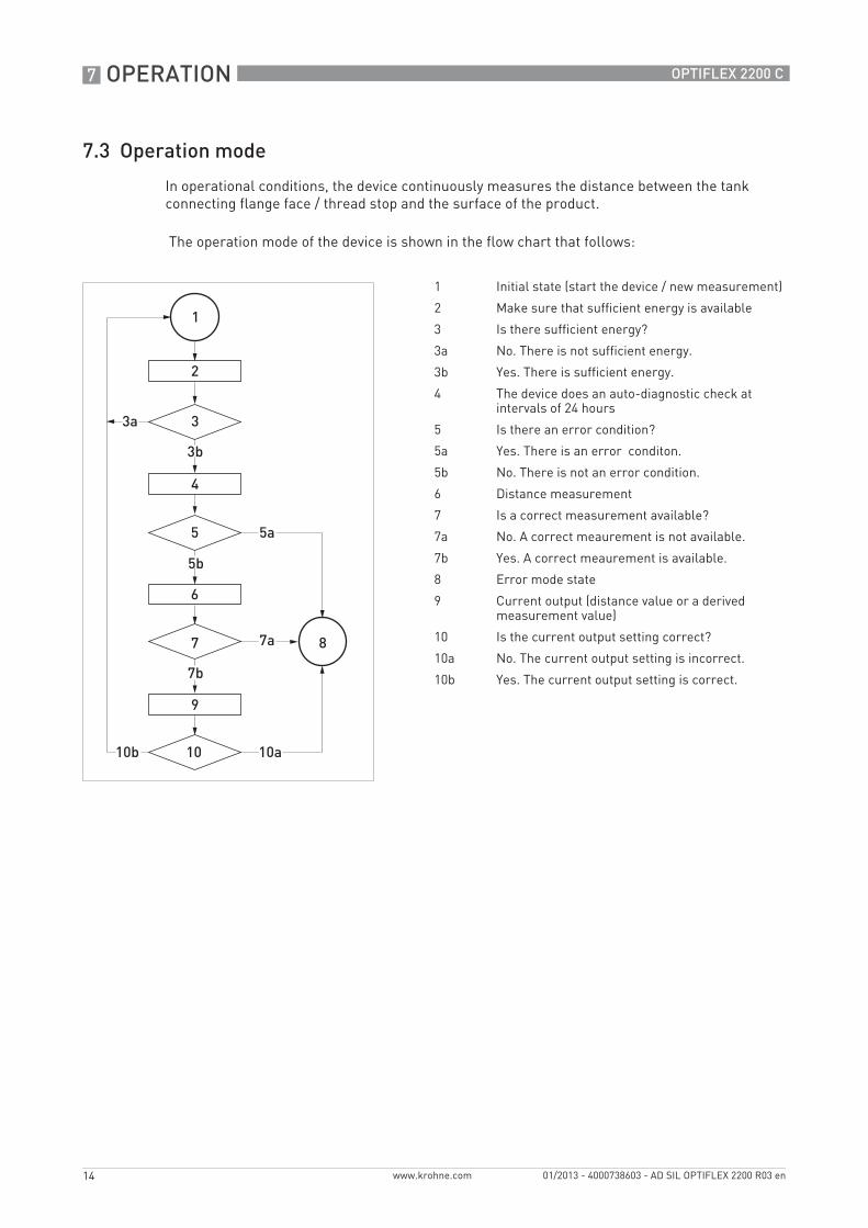
7.3 Operation mode
In operational conditions, the device continuously measures the distance between the tank connecting flange face / thread stop and the surface of the product.
The operation mode of the device is shown in the flow chart that follows:
1 Initial state (start the device / new measurement)
2 Make sure that sufficient energy is available
3 Is there sufficient energy?
3a No. There is not sufficient energy.
3b Yes. There is sufficient energy.
4 The device does an auto-diagnostic check at intervals of 24 hours
5 Is there an error condition?
5a Yes. There is an error conditon.
5b No. There is not an error condition.
6 Distance measurement
7 Is a correct measurement available?
7a No. A correct meaurement is not available.
7b Yes. A correct meaurement is available.
8 Error mode state
9 Current output (distance value or a derived measurement value)
10 Is the current output setting correct?
10a No. The current output setting is incorrect.
10b Yes. The current output setting is correct.

OPERATION 7
15
OPTIFLEX 2200 C
www.krohne.com01/2013 - 4000738603 - AD SIL OPTIFLEX 2200 R03 en
7.4 Error conditions
The device can sense the error conditions in the table that follows. When the device detects a measurement error, it supplies an output current less than 3.6 mA.
For more data, refer to the "Status and error messages" section in the handbook (document [N1]).
8 Error mode state
9 Current output (error value)
10 Is the current output setting correct?
10a No. The current output setting is incorrect.
10b Yes. The current output setting is correct.
11 Is a new correct measurement available?
11a No. A correct measurement is not available.
11b Yes. A correct measurement is available.
1 Initial state (new measurement)
Error condition Cause
Device does not start immediately
This error occurs if more than 20 seconds are necessary to start the device.
The current output is incorrectly calibrated
Do a current output check. For the procedure, refer to Current output check on page 23. If the values do not agree with the tolerances given in the procedure, speak to the supplier.
Component hardware errors Memory failure
Voltage failure
No signal
Microwave failure
Ambient temperature is too high The ambient temperature is more than +80°C / +176°F.
Ambient temperature is too low The ambient temperature is less than -40°C / -40°F.
Incorrect measurement signal (e.g. level lost)
The signal peak is not found within the measuring window that filters the signals received by the probe. The measurement is not correct.
Overfill The level is in the blocking distance. There is a risk that the product will overflow.
Measurement old The power supply is not sufficient to correctly measure the level.
7 OPERATION
16
OPTIFLEX 2200 C
www.krohne.com 01/2013 - 4000738603 - AD SIL OPTIFLEX 2200 R03 en
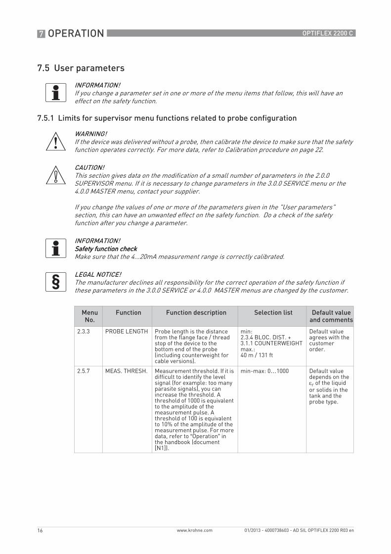
7.5 User parameters
7.5.1 Limits for supervisor menu functions related to probe configuration
INFORMATION!If you change a parameter set in one or more of the menu items that follow, this will have an effect on the safety function.
WARNING!If the device was delivered without a probe, then calibrate the device to make sure that the safety function operates correctly. For more data, refer to Calibration procedure on page 22.
CAUTION!This section gives data on the modification of a small number of parameters in the 2.0.0 SUPERVISOR menu. If it is necessary to change parameters in the 3.0.0 SERVICE menu or the 4.0.0 MASTER menu, contact your supplier.
If you change the values of one or more of the parameters given in the "User parameters" section, this can have an unwanted effect on the safety function. Do a check of the safety function after you change a parameter.
INFORMATION!Safety function checkSafety function checkSafety function checkSafety function checkMake sure that the 4...20mA measurement range is correctly calibrated.
LEGAL NOTICE!The manufacturer declines all responsibility for the correct operation of the safety function if these parameters in the 3.0.0 SERVICE or 4.0.0 MASTER menus are changed by the customer.
Menu No.
Function Function description Selection list Default value and comments
2.3.3 PROBE LENGTH Probe length is the distance from the flange face / thread stop of the device to the bottom end of the probe (including counterweight for cable versions).
min: 2.3.4 BLOC. DIST. + 3.1.1 COUNTERWEIGHTmax.:40 m / 131 ft
Default value agrees with the customer order.
2.5.7 MEAS. THRESH. Measurement threshold. If it is difficult to identify the level signal (for example: too many parasite signals), you can increase the threshold. A threshold of 1000 is equivalent to the amplitude of the measurement pulse. A threshold of 100 is equivalent to 10% of the amplitude of the measurement pulse. For more data, refer to “Operation” in the handbook (document [N1]).
min-max: 0…1000 Default value depends on the εr of the liquid or solids in the tank and the probe type.

OPERATION 7
17
OPTIFLEX 2200 C
www.krohne.com01/2013 - 4000738603 - AD SIL OPTIFLEX 2200 R03 en
7.5.2 Limits for supervisor menu functions related to device configuration
CAUTION!Make sure that:• 2.6.1 HART ADDRESS is set to "0". If it is not set to "0", the safety function will not operate
correctly.• 2.4.2 RANGE I is set to "4-20 / 3.6E" or "3.8-20.5 / 3.6E". If the error signal is set to "22 mA" or
"Hold", the safety function will not operate correctly.
Menu No.
Function Function description Selection list Default value and comments
2.3.1 TANK HEIGHT The distance from the tank connecting flange face / thread stop down to the tank bottom.
min-max:0…40 m / 0…131 ft
Default value agrees with the customer order
2.4.1 OUTPUT FUNC. The output function. Select an output function to scale the current values in relation to a given point (usually the device process connection or the tank bottom). The output current value is shown on a bar graph in normal mode if the measurement name is the same as the output function. Conversion parameters are shown if there is volume or mass data in 2.8.1 INPUT TABLE.
Distance, Level, Distance conversion, Level conversion
Default value agrees with the customer order
2.4.2 RANGE I This parameter sets the range of the output current with (3.8...20.5 mA) or without (4...20 mA) over-run values. It also tells the device what to do if an error occurs. For example, the device will change to an error value of 3.6 mA if you set RANGE I to "3.8-20.5/3.6E".
4-20, 4-20 / 22E, 4-20 / 3.6E,3.8-20.5 / 22E,3.8-20.5 / 3.6E
3.8-20.5 / 3.6E 1
2.4.3 SCALE 4mA This gives a measurement value to 4 mA.
min.-max: 2 Default value agrees with the customer order
2.4.4 SCALE 20mA This gives a measurement value to 20 mA.
min.-max: 2 Default value agrees with the customer order
2.4.5 ERROR DELAY The time after which the current output changes to an error value. The error value shows that there is a measurement error. MN=minutes and S=seconds.
0 S, 10 S, 20 S, 30 S, 1 MN, 2 MN, 5 MN,15 MN
0 S 3

7 OPERATION
18
OPTIFLEX 2200 C
www.krohne.com 01/2013 - 4000738603 - AD SIL OPTIFLEX 2200 R03 en
2.5.9 HART ADDRESS Any HART® address more than 0 will activate HART® multidrop mode.Multidrop mode is not Multidrop mode is not Multidrop mode is not Multidrop mode is not permitted for SIL-approved permitted for SIL-approved permitted for SIL-approved permitted for SIL-approved devices.devices.devices.devices.
min-max:0…15
0.Do not change.Do not change.Do not change.Do not change.
2.8.1 INPUT TAB. The device uses the conversion table to convert distance or level measurements to volume and mass readings. The readings are shown in normal mode.
min-max:0…30 conversion pairs
0
1 Use only "4-20 / 3.6E" or "3.8-20.5 / 3.6E"2 Units and range depend on the output function, length unit and volume unit selected3 If the safety function must immediately give a result, we recommend that you do not change this value
Menu No.
Function Function description Selection list Default value and comments

SERVICE 8
19
OPTIFLEX 2200 C
www.krohne.com01/2013 - 4000738603 - AD SIL OPTIFLEX 2200 R03 en
8.1 Periodic maintenance
You must obey the maintenance instructions given in the handbook (document [N1]).
8.2 Keep the device clean
For more data, refer to “Service” in the handbook (document [N1]).
8.3 Availability of services
The manufacturer offers a range of services to support the customer after expiration of the warranty. These include repair, maintenance, technical support and training.
8.4 Proof tests
It is neccessary to do proof tests to make sure that the safety function is applicable to the full measuring range.
• The device settings must be correct. If a parameter is incorrect, the device will not measure correctly.
• The electronic components must not be defective.• The software programs (firmware etc.) must operate correctly.• The probe must correctly transmit and receive the measurement signal. Parasitic signals
must not have an effect on the performance of the device.
We recommend that you do a proof test immediately after you install and start the device.
Prepare the device for the proof tests. Do a check of the device parameters.
INFORMATION!For more precise information, please contact your local sales office.
WARNING!SIS engineers must calculate the interval of proof tests. The minimum time between proof tests must be less than 5 years, but the interval between proof tests must also agree with the safety system used on site.
CAUTION!• Proof tests done by the customer must be equivalent or more difficult than the tests given in
this section.• Keep a report of each proof test. These reports must include the date, the tests results
(performance of the safety function or faults found), a list of approved personnel who did the test and the report revision number. These reports must be put into storage and made easily available. A proof test report form (for copying) is available on page 32.
• The location of the device and how it is installed on the tank can have an effect on the performance. Make sure that you obey the installation instructions given in the handbook.

8 SERVICE
20
OPTIFLEX 2200 C
www.krohne.com 01/2013 - 4000738603 - AD SIL OPTIFLEX 2200 R03 en
Equipment needed:• Device with the integrated display option• Process measurement and device configuration software (e.g. the DTM for PACTware™), if
the device does not have the integrated display option• Ammeter• Reference device: an approved level meter or indicator
Do a check of the 4 mA and the 20 mA settings:• Find the data for the 4 mA and the 20 mA settings in the SIS specification.• Enter the supervisor menu. For more data on how to get access to the supervisor menu, refer
to the "Operation" chapter of the handbook (document [N1]).• Push [>>>>] to go to menu item COMMISSION. (2.1.1). Push 4 × [>>>>] to see the SCALE 4mA valuei If the 4mA scale does not agree with the SIS specification, make sure that this data is
correct. If necessary, change the value and record the new value in the proof test report.
• Push [>>>>] to see the SCALE 20mA value.i If the 20mA scale does not agree with the SIS specification, make sure that this data is
correct. If necessary, change the value and record the new value in the proof test report.
Do a check of the tank height:• Measure the height of the tank or the silo (or the depth of the pit).• Enter the supervisor menu. For more data on how to get access to the supervisor menu, refer
to the "Operation" chapter of the handbook (document [N1]).• Push [>>>>] to go to menu item COMMISSION. (2.1.1). Push [>>>>] to see the TANK HEIGHT value.i Make sure that the value shown agrees with the tank height. If necessary, change the value
and record the new value in the proof test report.
Do a check of the device settings:• Use a tape measure to measure the probe length.• Enter the supervisor menu. For more data on how to get access to the supervisor menu, refer
to the "Operation" chapter of the handbook (document [N1]).• Push [ ], [ ], [>>>>], [ ] and [ ] to go to menu item PROBE LENGTH (2.3.3). Push [>>>>] to see the
value.i Make sure that the measured probe length agrees with the probe length shown in the
device menu. If necessary, change the value and record the new value in the proof test report.
• Push [^̂̂̂], [^̂̂̂], [ ], [>>>>] and [ ] to go to menu item RANGE I (2.4.2). Push [>>>>] to see the value.i Make sure that the current output range is set to "4-20 / 3.6E" or "3.8-20.5 / 3.6E". If
necessary, change the value and record the new value in the proof test report.
• Push [^̂̂̂], [^̂̂̂], [ ], [ ] and [>>>>] to go to menu item HART ADDRESS (2.6.1). Push [>>>>] to see the value.
CAUTION!Did you change the values of the supervisor menu functions given in the "User parameters" Did you change the values of the supervisor menu functions given in the "User parameters" Did you change the values of the supervisor menu functions given in the "User parameters" Did you change the values of the supervisor menu functions given in the "User parameters" section?section?section?section?If you change the values in supervisor menu items 2.4.2 RANGE I and 2.6.1 HART ADDRESS, the manufacturer cannot guarantee that the safety function will operate correctly. For more data, contact your supplier.

SERVICE 8
21
OPTIFLEX 2200 C
www.krohne.com01/2013 - 4000738603 - AD SIL OPTIFLEX 2200 R03 en
i Make sure that this menu item is set to 0000. If the value is not set to 0000, the safety function will not operate correctly.
Do a check of the low error alarm signal:• Enter the supervisor menu. For more data on how to get access to the supervisor menu, refer
to the "Operation" chapter of the handbook (document [N1]).• Push [ ] and [>>>>] to go to menu item SET OUTPUT (2.2.1).• Do a functional test of the low error alarm signal. Set the menu item SET OUTPUT (2.2.1) to
3.5 mA3.5 mA3.5 mA3.5 mA.i The output will change to 3.5 mA. This output is not related to the measured value. Does the
device give a "low error" alarm signal? If there is no alarm signal, the safety function will not operate correctly.
Measure the level and current output of the product in the tank at 3 points (example procedure given):• Find the data for the 4 mA and the 20 mA settings in the SIS specification.• Fill the tank to the maximum level (without overfill). Measure the level of the product in the
tank with an approved level meter or indicator (reference device).• Measure the output current with an ammeter.i If the menu item OUTPUT FUNC. (2.4.1) is set to LevelLevelLevelLevel, make sure the output current value
is 20 mA. If the menu item OUTPUT FUNC. (2.4.1) is set to DistanceDistanceDistanceDistance, make sure the output current value is 4 mA.
• Remove the product from the tank until it is 50% full. Measure the level of the product in the tank with an approved level meter or indicator (reference device).
• Measure the output current with an ammeter.i Make sure the output current value is 12 mA.
• Remove the product from the tank to the minimum level. Measure the level of the product in the tank with an approved level meter or indicator (reference device).
• Measure the output current with an ammeter.i If the menu item OUTPUT FUNC. (2.4.1) is set to LevelLevelLevelLevel, make sure the output current value
is 4 mA. If the menu item OUTPUT FUNC. (2.4.1) is set to DistanceDistanceDistanceDistance, make sure the output current value is 20 mA.
INFORMATION!The device is set to the "low" error alarm signal before delivery.
INFORMATION!Make sure that the current output value linearly decreases from 20 mA to 4 mA, if the menu item OUTPUT FUNC. (2.4.1) is set to LevelLevelLevelLevel. Make sure that the current output value linearly increases from 4 mA to 20 mA, if the menu item OUTPUT FUNC. (2.4.1) is set to DistanceDistanceDistanceDistance.The distance between 2 points in the tank must be as large as possible. We recommend that there is a space of at least 1 m / 3.3 ft between 2 points in the tank.You can adapt this procedure to special conditions. For example, if you use the safety function to prevent an overfill, it is not necessary to remove the product from the tank to the minimum level. It is only necessary to measure the level and current output of the product in the tank when it is full (without overfill). and 50% full.
8 SERVICE
22
OPTIFLEX 2200 C
www.krohne.com 01/2013 - 4000738603 - AD SIL OPTIFLEX 2200 R03 en
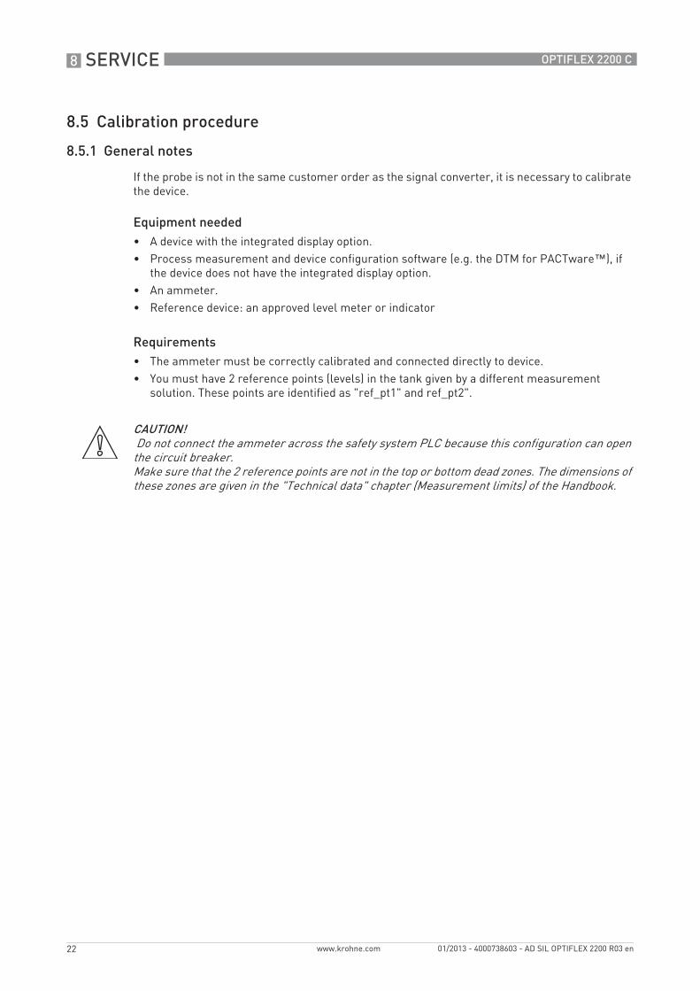
8.5 Calibration procedure
8.5.1 General notes
If the probe is not in the same customer order as the signal converter, it is necessary to calibrate the device.
Equipment needed• A device with the integrated display option.• Process measurement and device configuration software (e.g. the DTM for PACTware™), if
the device does not have the integrated display option.• An ammeter.• Reference device: an approved level meter or indicator
Requirements• The ammeter must be correctly calibrated and connected directly to device.• You must have 2 reference points (levels) in the tank given by a different measurement
solution. These points are identified as "ref_pt1" and ref_pt2".
CAUTION! Do not connect the ammeter across the safety system PLC because this configuration can open the circuit breaker.Make sure that the 2 reference points are not in the top or bottom dead zones. The dimensions of these zones are given in the "Technical data" chapter (Measurement limits) of the Handbook.

SERVICE 8
23
OPTIFLEX 2200 C
www.krohne.com01/2013 - 4000738603 - AD SIL OPTIFLEX 2200 R03 en
8.5.2 Current output check
Do a check of the current output value: 4 mA• Energize the device.• Enter the Supervisor menu.• Push [>>>>], [ ] and [>>>>] to go to menu item 2.2.1 SET OUTPUT. Push [>>>>] and then push [ ] or [ ]
to move up or down the list to set the output to 4 mA.i The output will change to the set value after 5 seconds, as an alternative to the measured
value. The current ouput stays at this value while you are in this menu item.
• Measure the current output at the terminals with an ammeter. Does the ammeter show a current output of 4 mA ± 400 µA?
• Push [^̂̂̂] to go back to the menu list.i The current output goes back to the measured value.
• End of the procedure.
Do a check of the current output value: 12 mA• Push [>>>>] and then push [ ] or [ ] to move up or down the list in menu item 2.2.1 SET OUTPUT
to set the output to 12 mA.i The output will change to the set value after 5 seconds, as an alternative to the measured
value. The current ouput stays at this value while you are in this menu item.
• Measure the current output at the terminals with an ammeter. Does the ammeter show a current output of 12 mA ± 400 µA?
• Push [^̂̂̂] to go back to the menu list.i The current output goes back to the measured value.
• End of the procedure.
Do a check of the current output value: 20 mA• Push [>>>>] and then push [ ] or [ ] to move up or down the list in menu item 2.2.1 SET OUTPUT
to set the output to 12 mA.i The output will change to the set value after 5 seconds, as an alternative to the measured
value. The current ouput stays at this value while you are in this menu item.
• Measure the current output at the terminals with an ammeter. Does the ammeter show a current output of 12 mA ± 400 µA?
• Push [^̂̂̂] to go back to the menu list.i The current output goes back to the measured value.
• End of the procedure.
CAUTION!If the values do not agree with the tolerances, then the data supplied by device will not be correct. For a solution to the problem, speak to the supplier.
8 SERVICE
24
OPTIFLEX 2200 C
www.krohne.com 01/2013 - 4000738603 - AD SIL OPTIFLEX 2200 R03 en
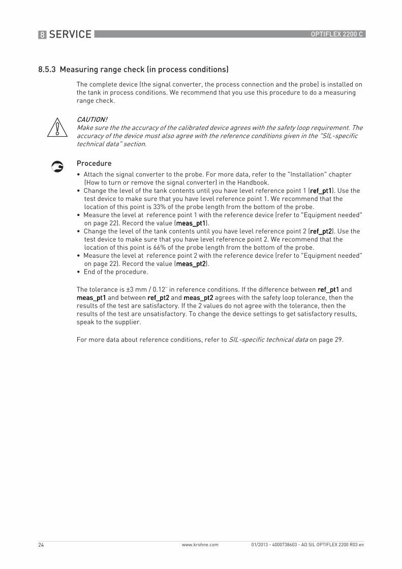
8.5.3 Measuring range check (in process conditions)
The complete device (the signal converter, the process connection and the probe) is installed on the tank in process conditions. We recommend that you use this procedure to do a measuring range check.
Procedure• Attach the signal converter to the probe. For more data, refer to the "Installation" chapter
(How to turn or remove the signal converter) in the Handbook.• Change the level of the tank contents until you have level reference point 1 (ref_pt1ref_pt1ref_pt1ref_pt1). Use the
test device to make sure that you have level reference point 1. We recommend that the location of this point is 33% of the probe length from the bottom of the probe.
• Measure the level at reference point 1 with the reference device (refer to "Equipment needed" on page 22). Record the value (meas_pt1meas_pt1meas_pt1meas_pt1).
• Change the level of the tank contents until you have level reference point 2 (ref_pt2ref_pt2ref_pt2ref_pt2). Use the test device to make sure that you have level reference point 2. We recommend that the location of this point is 66% of the probe length from the bottom of the probe.
• Measure the level at reference point 2 with the reference device (refer to "Equipment needed" on page 22). Record the value (meas_pt2meas_pt2meas_pt2meas_pt2).
• End of the procedure.
The tolerance is ±3 mm / 0.12¨ in reference conditions. If the difference between ref_pt1ref_pt1ref_pt1ref_pt1 and meas_pt1meas_pt1meas_pt1meas_pt1 and between ref_pt2ref_pt2ref_pt2ref_pt2 and meas_pt2meas_pt2meas_pt2meas_pt2 agrees with the safety loop tolerance, then the results of the test are satisfactory. If the 2 values do not agree with the tolerance, then the results of the test are unsatisfactory. To change the device settings to get satisfactory results, speak to the supplier.
For more data about reference conditions, refer to SIL-specific technical data on page 29.
CAUTION!Make sure the the accuracy of the calibrated device agrees with the safety loop requirement. The accuracy of the device must also agree with the reference conditions given in the "SIL-specific technical data" section.

SERVICE 8
25
OPTIFLEX 2200 C
www.krohne.com01/2013 - 4000738603 - AD SIL OPTIFLEX 2200 R03 en
8.6 Troubleshooting
If you find a problem, please contact your local representative. If the device must go back to the manufacturer, refer to "Returning the device to the manufacturer" in this supplement.
8.7 Returning the device to the manufacturer
8.7.1 General information
This device has been carefully manufactured and tested. If installed and operated in accordance with these operating instructions, it will rarely present any problems.
INFORMATION!• Modifications to the device are not permitted.• Only approved personnel can repair the device.
CAUTION!Should you nevertheless need to return a device for inspection or repair, please pay strict attention to the following points:• Due to statutory regulations on environmental protection and safeguarding the health and
safety of our personnel, manufacturer may only handle, test and repair returned devices that have been in contact with products without risk to personnel and environment.
• This means that the manufacturer can only service this device if it is accompanied by the following certificate (see next section) confirming that the device is safe to handle.
CAUTION!If the device has been operated with toxic, caustic, flammable or water-endangering products, you are kindly requested:• to check and ensure, if necessary by rinsing or neutralising, that all cavities are free from
such dangerous substances,• to enclose a certificate with the device confirming that is safe to handle and stating the
product used.

8 SERVICE
26
OPTIFLEX 2200 C
www.krohne.com 01/2013 - 4000738603 - AD SIL OPTIFLEX 2200 R03 en
8.7.2 Form (for copying) to accompany a returned device
Company: Address:
Department: Name:
Tel. no.: Fax no.:
Manufacturer's order no. or serial no.:
The device has been operated with the following medium:
This medium is: water-hazardous
toxic
caustic
flammable
We checked that all cavities in the device are free from such substances.
We have flushed out and neutralized all cavities in the device.
We hereby confirm that there is no risk to persons or the environment through any residual media contained in the device when it is returned.
Date: Signature:
Stamp:
TECHNICAL DATA 9
27
OPTIFLEX 2200 C
www.krohne.com01/2013 - 4000738603 - AD SIL OPTIFLEX 2200 R03 en
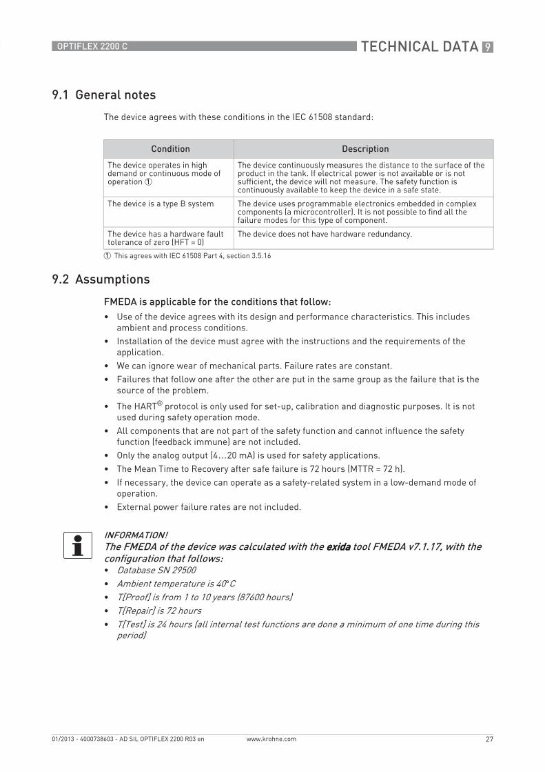
9.1 General notes
The device agrees with these conditions in the IEC 61508 standard:
9.2 Assumptions
FMEDA is applicable for the conditions that follow:• Use of the device agrees with its design and performance characteristics. This includes
ambient and process conditions.• Installation of the device must agree with the instructions and the requirements of the
application.• We can ignore wear of mechanical parts. Failure rates are constant.• Failures that follow one after the other are put in the same group as the failure that is the
source of the problem.
• The HART® protocol is only used for set-up, calibration and diagnostic purposes. It is not used during safety operation mode.
• All components that are not part of the safety function and cannot influence the safety function (feedback immune) are not included.
• Only the analog output (4…20 mA) is used for safety applications.• The Mean Time to Recovery after safe failure is 72 hours (MTTR = 72 h).• If necessary, the device can operate as a safety-related system in a low-demand mode of
operation.• External power failure rates are not included.
Condition Description
The device operates in high demand or continuous mode of operation 1
The device continuously measures the distance to the surface of the product in the tank. If electrical power is not available or is not sufficient, the device will not measure. The safety function is continuously available to keep the device in a safe state.
The device is a type B system The device uses programmable electronics embedded in complex components (a microcontroller). It is not possible to find all the failure modes for this type of component.
The device has a hardware fault tolerance of zero (HFT = 0)
The device does not have hardware redundancy.
1 This agrees with IEC 61508 Part 4, section 3.5.16
INFORMATION!The FMEDA of the device was calculated with the exidaexidaexidaexida tool FMEDA v7.1.17, with the configuration that follows:• Database SN 29500• Ambient temperature is 40°C• T[Proof] is from 1 to 10 years (87600 hours)• T[Repair] is 72 hours• T[Test] is 24 hours (all internal test functions are done a minimum of one time during this
period)

9 TECHNICAL DATA
28
OPTIFLEX 2200 C
www.krohne.com 01/2013 - 4000738603 - AD SIL OPTIFLEX 2200 R03 en
9.3 Characteristics for the device safety function
If it is necessary to use the device in a low demand mode (as specified in document [N2]), refer to the table below. For example, the device can be used to give a warning if an error signal occurs. The table shows the change of PFDAVG with a T[Proof] between 1 to 10 years:
For more data, refer to Proof tests on page 19.
Version Non-Ex / Ex i Ex d
Firmware version Converter: 1.06.02; Sensor: 1.21.02
Board version Converter: 4000678801B;Sensor: 4000786001B
Converter: 4000678801B;Sensor: 4000786001BEx d barrier: 4000633801A
Systematic capability 2 2
Architecture 1oo1D (daily auto-diagnostic checks)
PFH 6.50×10⁻⁸ 1.08×10⁻⁷
SFF 94% 91.7%
λSD 3.46×10⁻⁸ 1.09×10⁻⁷
λSU 4.71×10⁻⁷ 4.71×10⁻⁷
λDD 5.71×10⁻⁷ 6.81×10⁻⁷
λDU 6.50×10⁻⁸ 1.08×10⁻⁷
DCD 90% 86%
MTBF 99 years 83 years
Year: 1 2 3 4 5 6 7 8 9 10
PFDAVG(Non-Ex / Ex i)
2.88×10⁻⁴
5.74×10⁻⁴
8.59×10⁻⁴
1.14×10⁻³
1.43×10⁻³
1.71×10⁻³
2.00×10⁻³
2.28×10⁻³
2.56×10⁻³
2.85×10⁻³
PFDAVG(Ex d)
4.78×10⁻⁴
9.52×10⁻⁴
1.43×10⁻³
1.90×10⁻³
2.37×10⁻³
2.84×10⁻³
3.32×10⁻³
3.79×10⁻³
4.26×10⁻³
4.73×10⁻³

TECHNICAL DATA 9
29
OPTIFLEX 2200 C
www.krohne.com01/2013 - 4000738603 - AD SIL OPTIFLEX 2200 R03 en
9.4 SIL-specific technical data
INFORMATION!This data is for SIL-approved devices only. For more data about device characteristics and performance, refer to “Technical data” in the technical datasheet, quick start or handbook (document [N1]).
Measuring systemMeasuring principle 2-wire loop-powered level transmitter; Time Domain Reflectometry (TDR )
Application range Distance measurement of 1 product
Secondary measured value Distance, level and volume
DesignProbe options All basic probe options
Interface languages English, German, French, Italian, Spanish, Portuguese, Japanese, Chinese (Mandarin) and Russian
AccuracyResolution 1 mm / 0.04¨
Repeatability ±1 mm / ±0.04¨
Accuracy (in direct mode) ±3 mm / ±0.1¨, when distance ≤ 10 m / 33 ft;±0.03% of measured distance, when distance > 10 m / 33 ft 1
Accuracy (in TBF mode) ±20 mm / ±0.8¨ (εr constant)
Operating conditionsTemperatureTemperatureTemperatureTemperature
Ambient temperature -40…+80°C / -40…+175°F;Ex: see supplementary operating instructions or approval certificates
PressurePressurePressurePressure
Operating pressure -1…40 barg / -14.5…580 psig;subject to process connection temperature and probe type used
Other conditionsOther conditionsOther conditionsOther conditions
Dielectric constant (εr) Distance in direct mode:Distance in direct mode:Distance in direct mode:Distance in direct mode:≥1.4 for coaxial probe; ≥1.6 for double probes; ≥1.8 for single probes
Distance in TBF mode:Distance in TBF mode:Distance in TBF mode:Distance in TBF mode:≥1.1
MaterialHousing(compact version only)
Standard: Aluminium
Option: Stainless steel (1.4404 / 316L)
Single rod Standard: Stainless steel (1.4404 / 316L)
Option: Hastelloy® C-22 (2.4602) 2
Double rod Standard: Stainless steel (1.4404 / 316L)
Option: Hastelloy® C-22 (2.4602) 2
Coaxial Standard: Stainless steel (1.4404 / 316L)
Option: Hastelloy® C-22 (2.4602) 2

9 TECHNICAL DATA
30
OPTIFLEX 2200 C
www.krohne.com 01/2013 - 4000738603 - AD SIL OPTIFLEX 2200 R03 en
9.5 Support for SIL-approved devices
If the manufacturer makes a modification that has an effect on the safety function of the device, the manufacturer will tell you about the modification immediately.
Single cable Standard: Stainless steel (1.4401 / 316)
Option: Hastelloy® C-22 (2.4602) 2
Double cable Stainless steel (1.4401 / 316)
Electrical connectionsPower supply Terminals output - Non-Ex / Ex i:Terminals output - Non-Ex / Ex i:Terminals output - Non-Ex / Ex i:Terminals output - Non-Ex / Ex i:
12…30 VDC; min./max. value for an output of 22 mA at the terminal
Terminals output - Ex d:Terminals output - Ex d:Terminals output - Ex d:Terminals output - Ex d:16…36 VDC; min./max. value for an output of 22 mA at the terminal
Input and outputCurrent outputCurrent outputCurrent outputCurrent output
Resolution ±1 µA
Error signal Low: ≤ 3.6 mA acc. to NAMUR NE 43
Error tolerance If an error is >2.5% of the output signal, this error has a "dangerous undetected failure" status.
HARTHARTHARTHART®
Description HART® protocol via passive current output 3
Point-to-point operation Yes. Current output = 4 mA. HART® Address = 0. Output current data that is transmitted in less than 1 ms is ignored (this data filter agrees with HART® protocol requirements).
Multidrop operation Multidrop operation is not permitted because the current output (safety function) must be set to 4 mA. Thus, the safety function cannot supply data about the device status.
PROFIBUS PAPROFIBUS PAPROFIBUS PAPROFIBUS PA
Description Not yet available. This option is not permitted.
FOUNDATIONFOUNDATIONFOUNDATIONFOUNDATION™ Fieldbus Fieldbus Fieldbus Fieldbus
Description Not yet available. This option is not permitted.
ModbusModbusModbusModbus
Description Not yet available. This option is not permitted.
Other dataOther dataOther dataOther data
Response time (errors) Response time = value given in supervisor menu item 2.4.5 ERROR DELAYIf electrical power is not sufficient for correct operation of the device (worst conditions for operation), the error is shown in less than 10 seconds.
Diagnostic test frequency 1 time / day (firmware does an auto-diagnostic test)
Approvals and certificationSIL SIL 2 4
Agrees with IEC 61508:2010 Parts 1 to 7
1 This option must be selected by the customer2 Hastelloy® is a registered trademark of Haynes International, Inc.3 HART® is a registered trademark of the HART Communication Foundation4 When only one liquid is in the tank
APPENDIX 10
31
OPTIFLEX 2200 C
www.krohne.com01/2013 - 4000738603 - AD SIL OPTIFLEX 2200 R03 en
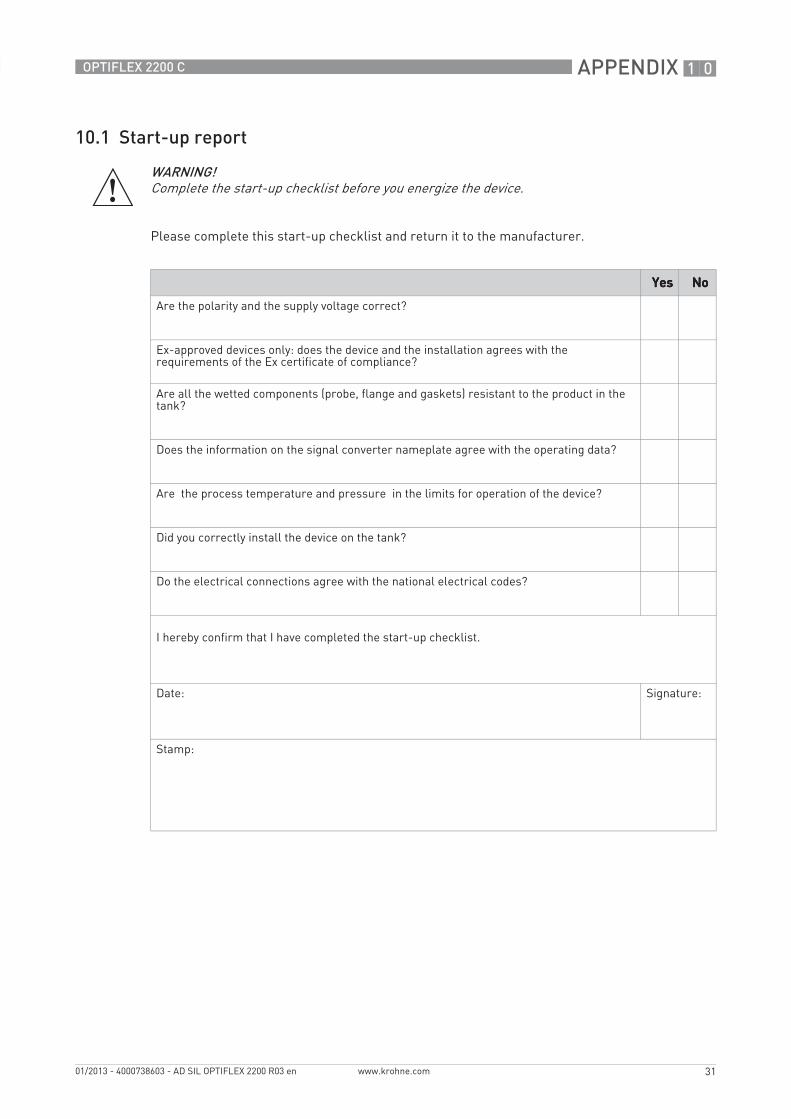
10.1 Start-up report
Please complete this start-up checklist and return it to the manufacturer.
WARNING!Complete the start-up checklist before you energize the device.
YesYesYesYes NoNoNoNo
Are the polarity and the supply voltage correct?
Ex-approved devices only: does the device and the installation agrees with the requirements of the Ex certificate of compliance?
Are all the wetted components (probe, flange and gaskets) resistant to the product in the tank?
Does the information on the signal converter nameplate agree with the operating data?
Are the process temperature and pressure in the limits for operation of the device?
Did you correctly install the device on the tank?
Do the electrical connections agree with the national electrical codes?
I hereby confirm that I have completed the start-up checklist.
Date: Signature:
Stamp:

10 APPENDIX
32
OPTIFLEX 2200 C
www.krohne.com 01/2013 - 4000738603 - AD SIL OPTIFLEX 2200 R03 en
10.2 Proof test report form (for copying)
For more data, refer to Proof tests on page 19.
CAUTION!Complete the report form that follows when you do a proof test.
Recorded by: Date:
Unique device ID (e.g. serial number):
Parameter value check
Proof tests results
Recorded value Correct value Approved
2.3.1 TANK HEIGHT Correct tank height [Yes] [No]
2.4.3 SCALE 4mA 4.000 mA ± 1 μA [Yes] [No]
2.4.4 SCALE 20mA 20.000 mA ± 1 μA [Yes] [No]
2.3.3 PROBE LENGTH Correct probe length [Yes] [No]
2.4.2 RANGE I Error value= 3.6 mA 1 [Yes] [No]
2.6.1 HART ADDRESS HART address= 0 2 [Yes] [No]
1 The error value is correct if the menu item is set to "4-20/3.6E" or "3.8-20.5/3.6E"2 Multidrop is not permitted for SIL-approved devices
Functional check
Proof tests results
Recorded value Correct value Approved
Error alarm signal < 3.6 mA < 3.6 mA [Yes] [No]
Current output= 4 mA 1 4 mA ± 400 μA [Yes] [No]
Current output= 12 mA 2 12.000 mA ± 400 μA [Yes] [No]
Current output= 20 mA 3 20.000 mA ± 400 μA [Yes] [No]
1 The tank is full when menu item 2.4.1 OUTPUT FUNC.= Distance. The tank is empty when menu item 2.4.1 OUTPUT FUNC.= Level.
2 The tank is 50% full.3 The tank is full when menu item 2.4.1 OUTPUT FUNC.= Level. The tank is empty when menu item 2.4.1 OUTPUT FUNC.=
Distance.
Conclusion
Does the device operate satisfactorily in safety-related systems? [Yes] [No]
Signature:

NOTES 11
33
OPTIFLEX 2200 C
www.krohne.com01/2013 - 4000738603 - AD SIL OPTIFLEX 2200 R03 en

11 NOTES
34
OPTIFLEX 2200 C
www.krohne.com 01/2013 - 4000738603 - AD SIL OPTIFLEX 2200 R03 en

NOTES 11
35
OPTIFLEX 2200 C
www.krohne.com01/2013 - 4000738603 - AD SIL OPTIFLEX 2200 R03 en

KROHNE product overview
• Electromagnetic flowmeters
• Variable area flowmeters
• Ultrasonic flowmeters
• Mass flowmeters
• Vortex flowmeters
• Flow controllers
• Level meters
• Temperature meters
• Pressure meters
• Analysis products
• Products and systems for the oil & gas industry
• Measuring systems for the marine industry
Head Office KROHNE Messtechnik GmbHLudwig-Krohne-Str. 547058 Duisburg (Germany)Tel.:+49 (0)203 301 0Fax:+49 (0)203 301 10389 [email protected]
© K
RO
HN
E 01
/201
3 -
4000
7386
03 -
AD
SIL
OP
TIFL
EX 2
200
R03
en
- Su
bjec
t to
chan
ge w
ithou
t not
ice.
The current list of all KROHNE contacts and addresses can be found at:www.krohne.com