Embed Size (px)
Citation preview
OPTIFLEX 1300 COPTIFLEX 1300 COPTIFLEX 1300 COPTIFLEX 1300 C Technical DatasheetTechnical DatasheetTechnical DatasheetTechnical Datasheet
Guided Radar (TDR) Level Meter
• Universal device that can measure level of liquids, pastes, granulates, powders, and liquid interface
• Easy to install: onsite calibration is not needed • Operates up to 300 bar / 4350 psi
© KROHNE 09/2010 - 4000112206 - TD OPTIFLEX 1300 R11 en

CONTENTS
2 www.krohne.com 09/2010 - 4000112206 - TD OPTIFLEX 1300 R11 en
OPTIFLEX 1300 C
1 Product features 4
1.1 The superior TDR solution ............................................................................................... 41.2 Applications ...................................................................................................................... 61.3 Measuring principle.......................................................................................................... 8
2 Technical data 11
2.1 Technical data................................................................................................................. 112.2 Application table for probe selection ............................................................................. 172.3 Pressure/temperature table for probe selection .......................................................... 182.4 Measurement limits ....................................................................................................... 192.5 Dimensions and weights ................................................................................................ 22
3 Installation 36
3.1 Intended use ................................................................................................................... 363.2 Pre-installation requirements ....................................................................................... 363.3 How to prepare the tank before you install the device.................................................. 36
3.3.1 General information for nozzles........................................................................................... 363.3.2 Installation requirements for concrete roofs....................................................................... 38
3.4 Installation recommendations for liquids...................................................................... 393.4.1 General requirements .......................................................................................................... 393.4.2 Standpipes............................................................................................................................. 40
3.5 Installation recommendations for solids....................................................................... 443.5.1 Nozzles on conical silos........................................................................................................ 443.5.2 Traction loads on the probe.................................................................................................. 46
3.6 How to install the device on the tank ............................................................................. 473.6.1 How to install a device with a flange connection ................................................................. 473.6.2 How to install a device with a threaded connection ............................................................. 473.6.3 Installation recommendations for non-metallic tanks and pits .......................................... 483.6.4 How to assemble the remote housing.................................................................................. 49
4 Electrical connections 50
4.1 Safety instructions.......................................................................................................... 504.2 Electrical installation: outputs 1 and 2 .......................................................................... 50
4.2.1 Non-Ex................................................................................................................................... 514.2.2 Ex i ......................................................................................................................................... 514.2.3 Ex d ........................................................................................................................................ 514.2.4 PROFIBUS PA........................................................................................................................ 514.2.5 FOUNDATION Fieldbus ......................................................................................................... 51
4.3 Protection category ........................................................................................................ 524.4 Networks ........................................................................................................................ 53
4.4.1 General information.............................................................................................................. 534.4.2 Point-to-point networks ....................................................................................................... 534.4.3 Multi-drop networks ............................................................................................................. 544.4.4 Fieldbus networks................................................................................................................. 55

CONTENTS
3www.krohne.com09/2010 - 4000112206 - TD OPTIFLEX 1300 R11 en
OPTIFLEX 1300 C
5 Order form 57
5.1 Device data ..................................................................................................................... 575.2 Rating data...................................................................................................................... 585.3 Contact data.................................................................................................................... 58
6 Notes 59

1 PRODUCT FEATURES
4
OPTIFLEX 1300 C
www.krohne.com 09/2010 - 4000112206 - TD OPTIFLEX 1300 R11 en
1.1 The superior TDR solution
This device is a Guided Radar (TDR) Level Meter for measuring distance, level, interface, level and interface, volume and mass. It has higher signal dynamics and a sharper pulse than conventional TDR devices and therefore better reproducibility and accuracy. A variant with a remote converter can be mounted up to 14.5 m / 47.6 ft from the probe. The device can operate at very low and very high process temperatures as long as the process connection temperature limits are observed.
1 Touch screen with 4-button operation2 2-wire level meter3 Converter is rotatable and removable under process conditions4 5 different types of probes suitable for a wide range of media5 Optional ESD protection (30 kV) or Metaglas® dual process sealing system for dangerous products6 Same converter for Ex and non-Ex7 Large graphical display

PRODUCT FEATURES 1
5
OPTIFLEX 1300 C
www.krohne.com09/2010 - 4000112206 - TD OPTIFLEX 1300 R11 en
Highlights• Displays level and interface• PACTware and DTMs included as standard• Optional FOUNDATION™ Fieldbus and PROFIBUS PA outputs• Optional second current output - used for displaying interface measurements, for example• High-pressure and high-temperature versions• Optimal process safety (with Metaglas® dual process sealing system for dangerous products)• Display in 9 languages: even in Chinese, Japanese and Russian• Available in stainless steel and Hastelloy® C-22. Other materials are available on request:
monel, tantalum, titanium, duplex, ...• Angled single cable and rod probes are available on request for installation in tanks which
contain obstructions
Industries• Chemicals & Petrochemicals• Oil & Gas• Minerals & Mining• Wastewater• Pulp & Paper• Food & Beverages• Pharmaceutical• Energy
Applications• Blending tanks• Distillation tanks• Process tanks• Separator• Solid silos (inventory)• Storage tanks

1 PRODUCT FEATURES
6
OPTIFLEX 1300 C
www.krohne.com 09/2010 - 4000112206 - TD OPTIFLEX 1300 R11 en
1.2 Applications
1. Level measurement of liquids
2. Interface measurement of liquids
The level meter can measure the level of a wide range of liquid products on a large variety of installations within the stated pressure and temperature range, including LPG and LNG. It does not require calibration or commissioning when installed. A Metaglas® option is also available for dangerous products and ensures that no leakage is possible.
A number of probe end attachments are available. For example, the user can fix the end of cable probes to heating coils: the heat prevents deposits building up on the probe.
The level meter can measure interface with or without an air gap. It can also measure level and interface simultaneously. It has an optional second analogue output.
The coaxial probe of the level meter has a top dead zone of only 10 mm / 0.4¨: this makes it ideal for tracking full tank or ballast interface.
PRODUCT FEATURES 1
7
OPTIFLEX 1300 C
www.krohne.com09/2010 - 4000112206 - TD OPTIFLEX 1300 R11 en
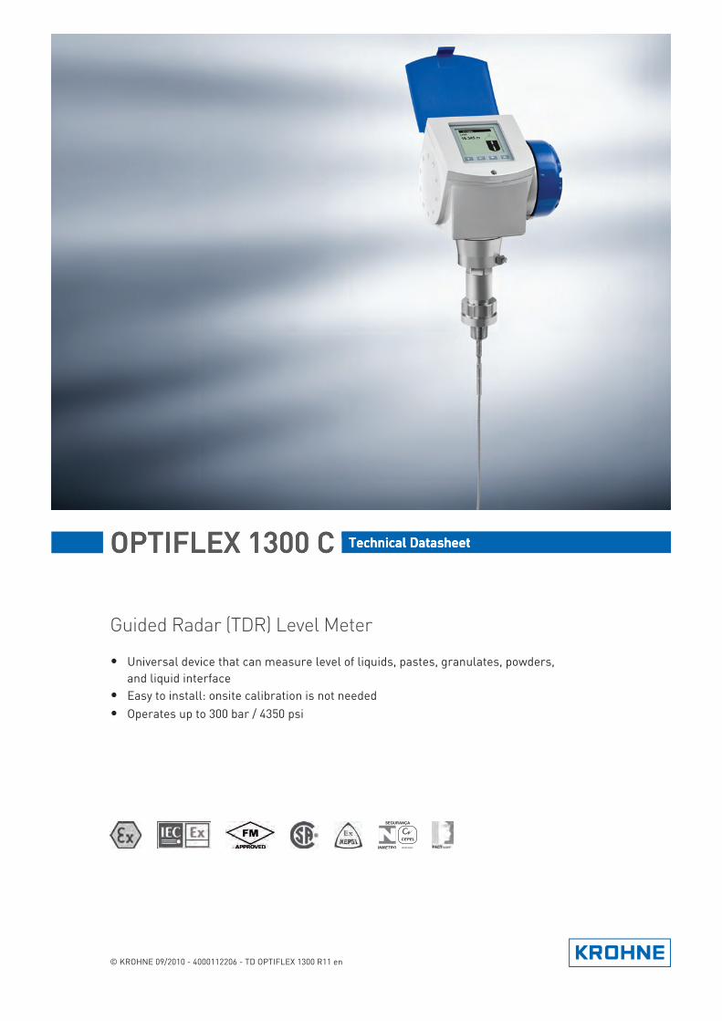
3. Level measurement of solids
4. Measurement of liquids in a bypass chamber
The level meter has a strengthened Ø8 mm / 0.3¨ single cable probe for measuring powders and granulates in silos up to 35 m / 115 ft high.
The Ø4 mm / 0.15¨ single cable probe is used for small silos. An ESD protection (30 kV) option is also available.
If a product has a very low dielectric constant (εr <1.6), the level meter automatically switches to TBF (Tank Bottom Following) mode and keeps operating.
The level meter can measure accurately in agitated conditions and in the presence of foam. If the tank is full of obstructions such as agitators and reinforcements, we recommend installing the level meter in a bypass chamber. This solution is available from KROHNE under the name BM 26 F. Please refer to the BM 26 F documentation for further information.

1 PRODUCT FEATURES
8
OPTIFLEX 1300 C
www.krohne.com 09/2010 - 4000112206 - TD OPTIFLEX 1300 R11 en
5. Measurement of liquids in a still well
6. Remote display on high or inaccessible tanks
1.3 Measuring principle
This Guided Radar (TDR) level meter has been developed from a proven technology called Time Domain Reflectometry (TDR).
The device transmits low-intensity electromagnetic pulses of approximately half a nanosecond width along a rigid or flexible conductor. These pulses move at the speed of light. When the pulses reach the surface of the product to be measured, the pulses are reflected with an intensity that depends on the dielectric constant, εr, of the product (for example, water has a high dielectric constant and reflects the pulse back to the meter converter at 80% of its original intensity).
The device measures the time from when the pulse is transmitted to when it is received: half of this time is equivalent to the distance from the reference point of the device (the flange facing) to the surface of the product. The time value is converted into an output current of 4...20 mA and/or a digital signal.
You can also install the level meter in a still well if there are vortices, agitators or other obstructions in the tank. It is also suitable for tanks with floating roofs. The level meter's setup wizard allows you to quickly configure your device to suit specific types of installations and get the best possible performance from it.
If it is difficult or impossible to read the level meter's integrated display at the top of the tank, we recommend the remote display variant. It is provided with a cable up to 14.5 m / 47.6 ft long and a bracket for mounting in an accessible position.If there is vibration in the installation, we also recommend that you attach the remote converter to a wall or another safe object that is not attached to the installation.

PRODUCT FEATURES 1
9
OPTIFLEX 1300 C
www.krohne.com09/2010 - 4000112206 - TD OPTIFLEX 1300 R11 en
Dust, foam, vapor, agitated surfaces, boiling surfaces, changes in pressure, changes in temperature and changes in density do not have an effect on device performance.
The illustration that follows shows a snapshot of what a user would see on an oscilloscope, if the level of one product is measured.
The illustration that follows shows a snapshot of what a user would see on an oscilloscope, if the level and/or interface of products are measured.
Level measurement principle (direct measurement)
Figure 1-1: Level measurement principle
1 Time 0: The electromagnetic (EM) pulse is transmitted by the converter2 Time 1: The pulse goes down the probe at the speed of light in air, V13 Time 2: The pulse is reflected4 Time 3: The pulse goes up the probe at speed, V15 Time 4: The converter receives the pulse and records the signal6 The EM pulse moves at speed, V17 Transmitted EM pulse8 Half of this time is equivalent to the distance from the reference point of the device (the flange facing) to the surface
of the product9 Received EM pulse
Interface measurement:Interface measurement:Interface measurement:Interface measurement: The dielectric constant of the top liquid must be less than the dielectric constant of the bottom liquid. If not, or if there is too small a difference, the device may not measure correctly.

1 PRODUCT FEATURES
10
OPTIFLEX 1300 C
www.krohne.com 09/2010 - 4000112206 - TD OPTIFLEX 1300 R11 en
If products have a very low dielectric constant (εr <1.6), only a small part of the EM pulse is reflected at the surface of the product. Most of the pulse is reflected at the probe end. TBF (tank bottom following) mode is used to measure the distance to the product surface.
TBF mode (indirect measurement) compares:
• The time for the pulse to go to the probe end and go back to the converter when the tank is empty.
• The time for the pulse to go to the probe end and go back to the converter when the tank is full or partially filled.
The level of the product in the tank can be calculated from the time difference.
Level and interface measurement principle (direct measurement)
Figure 1-2: Level and interface measurement principle (2 liquids in the tank)
1 Time 0: The electromagnetic (EM) pulse is transmitted by the converter2 Time 1: The pulse goes down the probe at the speed of light in air, V13 Time 2: Part of the pulse is reflected at the surface of the top liquid, the remaining pulse goes down the probe4 Time 3: Part of the pulse goes up the probe at speed, V1. The remaining pulse goes down the probe at the speed of
light in the top product, V25 Time 4: The converter receives part of the pulse pulse and records the signal. The remaining pulse is reflected at the
interface of the 2 liquids6 Time 5: The remaining pulse is goes up the probe at speed, V27 Time 6: The remaining pulse goes up the probe at speed, V18 Time 7: The converter receives the remaining pulse and records the signal9 The EM pulse moves at speed, V110 The EM pulse moves at speed, V211 Transmitted EM pulse12 Received EM pulse (distance to the top liquid)13 Received EM pulse (distance to the interface of 2 liquids)
TECHNICAL DATA 2
11
OPTIFLEX 1300 C
www.krohne.com09/2010 - 4000112206 - TD OPTIFLEX 1300 R11 en
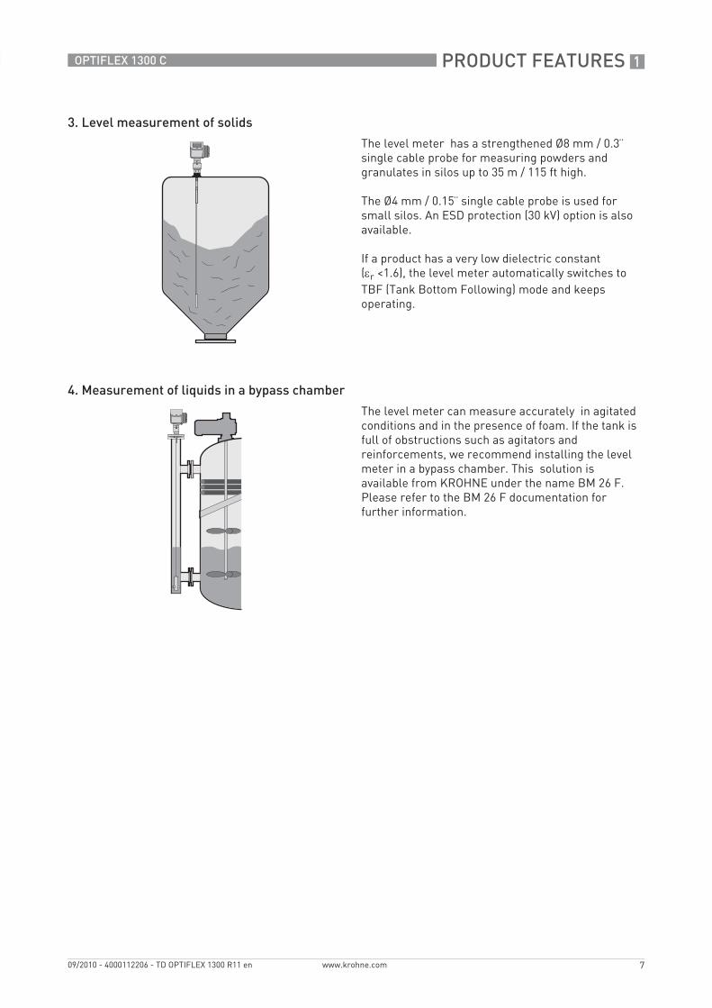
2.1 Technical data
• The following data is provided for general applications. If you require data that is more relevant to your specific application, please contact us or your local representative.
• Additional information (certificates, special tools, software,...) and complete product documentation can be downloaded free of charge from the website (Download Center).
Measuring systemMeasuring principle 2-wire loop-powered level transmitter; Time Domain Reflectometry (TDR)
Application range Level measurement of liquids, pastes, slurries, powders and granulates
Primary measured value Time between the emitted and received signal
Secondary measured value Distance, level, volume, mass and/or interface
DesignConstruction The measurement system consists of a measuring sensor (probe) and a signal
converter which is available in a compact or remote version
Options Integrated LCD display with sun cover (-20…+60°C / -4…+140°F);if the ambient temperature is not in these limits, the display switches off
2nd current output
ESD protection (max. 30 kV)
Metaglas® (dual process sealing system for dangerous products (ammonia, chlorine, ...)) 1
Remote housing connected to the probe via a flexible conduitStandard lengths: 2 m / 6.6 ft, 4.5 m / 14.8 ft, 9.5 m / 31.2 ft and 14.5 m / 47.6 ft
Probe end types (not for rod and coaxial probes)Probe end types (not for rod and coaxial probes)Probe end types (not for rod and coaxial probes)Probe end types (not for rod and coaxial probes)Standard: Counterweights (refer to counterweight dimensions in "Technical data: Dimensions and weights".)Options: Turnbuckle, chuck, threaded end, crimped end, open end
Accessories Weather protection
Max. measuring range Double rod Ø8 mm / 0.3¨: 4 m / 13 ft
Single rod Ø8 mm / 0.3¨: 4 m / 13 ft
Single rod Ø8 mm / 0.3¨ (segmented): 6 m / 20 ft
Coaxial Ø22 mm / 0.9¨: 6 m / 20 ft
Coaxial Ø22 mm / 0.9¨ (segmented): 6 m / 20 ft
Double cable Ø4 mm / 0.15¨: 8 m / 26 ft
Single cable Ø2 mm / 0.08¨: 35 m / 115 ft (for liquids only)
Single cable Ø4 mm / 0.15¨: 35 m / 115 ft (For liquids only. An angled probe is available on request for installations with very low ceilings or objects in the tank that prevent installation on top of the tank.)
Single cable Ø8 mm / 0.3¨: 35 m / 115 ft (For solids only. Tolerance, probe length: -1%/+0%.)
Dead zone This depends on the type of probe. For more data, refer to Measurement limits on page 19.
Display and User interfaceDisplay and User interfaceDisplay and User interfaceDisplay and User interface
Display LCD display
9 lines, 160×160 pixels in 8-step grayscale with 4-button keypad
Interface languages English, German, French, Italian, Spanish, Portuguese, Japanese, Chinese (Mandarin) and Russian

2 TECHNICAL DATA
12
OPTIFLEX 1300 C
www.krohne.com 09/2010 - 4000112206 - TD OPTIFLEX 1300 R11 en
AccuracyResolution 1 mm / 0.04¨
Repeatability ±1 mm / ±0.04¨
Accuracy (in direct mode) Liquids:Liquids:Liquids:Liquids:±3 mm / ±0.12¨, when distance < 10 m / 33 ft;±0.03% of measured distance, when distance > 10 m / 33 ft
Powders:Powders:Powders:Powders:±20 mm / ±0.8¨
Interface:Interface:Interface:Interface:±10 mm / ±0.4¨ (εr constant)
Accuracy (in TBF mode) ±20 mm / ±0.8¨ (εr constant)
Minimum layer (interface) 50 mm / 2¨
Reference conditions acc. to EN 60770Reference conditions acc. to EN 60770Reference conditions acc. to EN 60770Reference conditions acc. to EN 60770
Temperature +20°C ±5°C / +68°F ±10°F
Pressure 1013 mbara ±20 mbar / 14.69 psia ±0.29 psi
Relative air humidity 60% ±15%
Operating conditions TemperatureTemperatureTemperatureTemperature
Ambient temperature -40…+80°C / -40…+175°F(Ex: see supplementary operating instructions or approval certificates)
Storage temperature -40…+85°C / -40…+185°F
Process connection temperature StandardStandardStandardStandard-40…+200°C / -40…+390°F (according to the temperature limits of the gasket material. Refer to "Material" in this table.)(Ex: see supplementary operating instructions or approval certificates) 2
High-Temperature (HT) and High-Temperature / High-Pressure (HT/HP) versions High-Temperature (HT) and High-Temperature / High-Pressure (HT/HP) versions High-Temperature (HT) and High-Temperature / High-Pressure (HT/HP) versions High-Temperature (HT) and High-Temperature / High-Pressure (HT/HP) versions with FKM/FPM and Kalrezwith FKM/FPM and Kalrezwith FKM/FPM and Kalrezwith FKM/FPM and Kalrez® 6375 gaskets6375 gaskets6375 gaskets6375 gaskets+300°C / +570°F (single cable Ø2 mm / 0.08¨ probe only)(Ex: see supplementary operating instructions or approval certificates) 2
HT and HT/HP versions with EPDM gasketsHT and HT/HP versions with EPDM gasketsHT and HT/HP versions with EPDM gasketsHT and HT/HP versions with EPDM gaskets+250°C / +480°F (single cable Ø2 mm / 0.08¨ probe only)(Ex: see supplementary operating instructions or approval certificates) 2
Thermal shock resistance 100°C/min
PressurePressurePressurePressure
Operating pressure Single cable Ø8 mm / 0.3Single cable Ø8 mm / 0.3Single cable Ø8 mm / 0.3Single cable Ø8 mm / 0.3¨ probe probe probe probe-1…40 barg / -14.5…580 psigsubject to process connection temperature and probe type used 2
High-Pressure (HP) versionHigh-Pressure (HP) versionHigh-Pressure (HP) versionHigh-Pressure (HP) versionmax. 300 barg / 4350 psig (single cable Ø2 mm / 0.08¨ probe only)subject to process connection temperature and probe type used 2
All other probe typesAll other probe typesAll other probe typesAll other probe types-1…100 barg / -14.5…1450 psigsubject to process connection temperature and probe type used 2

TECHNICAL DATA 2
13
OPTIFLEX 1300 C
www.krohne.com09/2010 - 4000112206 - TD OPTIFLEX 1300 R11 en
Other conditionsOther conditionsOther conditionsOther conditions
Dielectric constant (εr) Level in direct mode:Level in direct mode:Level in direct mode:Level in direct mode:≥1.4 for coaxial probe; ≥1.6 for single and double probes
Interface in direct mode:Interface in direct mode:Interface in direct mode:Interface in direct mode:εr(interface) >> εr(level)²
Level in TBF mode:Level in TBF mode:Level in TBF mode:Level in TBF mode:≥1.1
Vibration resistance IEC 60068-2-6 and EN 50178 (10...57 Hz: 0.075 mm / 57...150 Hz:1g)
Protection category IP 66/67 equivalent to NEMA 6-6X
Installation conditionsProcess connection size Refer to "Installation: How to prepare the tank before you install the device" and
"Technical data: Measurement limits"
Process connection position Make sure that there are not any obstructions directly below the process connection for the device.
Dimensions and weights Refer to "Technical data: Dimensions and weights"
MaterialHousing Standard: Aluminium
Option: Stainless steel (1.4404 / 316L)
Single rod (single-piece) Standard: Stainless steel (1.4404 / 316L)
Option: Hastelloy® C-22 (2.4602) 3
On request: Stainless steel (1.4404 / 316L) in a PVC, PVDF or PP protective sheath
On request: Monel; Tantalum; Titanium; Duplex
Single rod (segmented) Standard: Stainless steel (1.4404 / 316L)
Double rod Standard: Stainless steel (1.4404 / 316L)
Option: Hastelloy® C-22 (2.4602)
On request: Monel; Tantalum; Titanium; Duplex
Coaxial (single-piece) Standard: Stainless steel (1.4404 / 316L)
Option: Hastelloy® C-22 (2.4602)
Coaxial (segmented) Standard: Stainless steel (1.4404 / 316L)
Single cable Standard: Stainless steel (1.4401 / 316)
Option: Hastelloy® C-22 (2.4602)- only for the Ø2 mm / 0.08¨ or Ø4 mm / 0.15¨ single cable probes
On request: FEP-coated stainless steel (-20...+150°C / -4...+300°F)- only for the Ø4 mm / 0.15¨ single cable probe
Double cable Stainless steel (1.4401 / 316)
Process fitting Standard: Stainless steel (1.4404 / 316 L)
Option: Hastelloy® C-22 (2.4602)
On request: Monel; Tantalum; Titanium; Duplex
Gaskets FKM/FPM (-40…+200°C / -40…+390°F); Kalrez® 6375 (-20…+200°C / -4…+390°F);EPDM (-50...+150°C / -58...+300°F) - all probes except single cable Ø8 mm / 0.3¨ 4
Weather protection (Option) Stainless steel (1.4301 / 304)
Protective sheath(On request for single rod only)
PP (-40…+90°C / -40…+194°F); PVC (-15…+80°C / +5…+176°F);PVDF (-40…+150°C / -40…+300°F)
Conduit for remote housing (Option)
Zinc-coated steel in a PVC sheath (-40...+105°C / -40...+220°F)

2 TECHNICAL DATA
14
OPTIFLEX 1300 C
www.krohne.com 09/2010 - 4000112206 - TD OPTIFLEX 1300 R11 en
Process connectionsThreadThreadThreadThread
Single cable Ø2 mm / 0.08¨ G ½; ½ NPT; ½ NPTF (for the HT/HP version)
Single cable Ø8 mm / 0.3¨ G 1½; 1½ NPT
All other probes G ¾…1½; ¾…1½ NPT
Flange versions for single cable Ø8 mm / 0.3Flange versions for single cable Ø8 mm / 0.3Flange versions for single cable Ø8 mm / 0.3Flange versions for single cable Ø8 mm / 0.3¨, double rod and double cable probes, double rod and double cable probes, double rod and double cable probes, double rod and double cable probes
EN DN40…150 in PN16, PN40, PN63 or PN100; others on request
ASME 1½¨…8¨ in 150 lb, 1½¨...6¨ in 300 lb, 1½¨...4¨ in 600 lb or 900 lb; 1½¨...2¨ in 1500 lb; others on request
JIS 40…100A in 10K; others on request
Flange versions for single cable Ø2 mm / 0.08Flange versions for single cable Ø2 mm / 0.08Flange versions for single cable Ø2 mm / 0.08Flange versions for single cable Ø2 mm / 0.08¨ probe probe probe probe
EN DN25…150 in PN16, PN40, PN63 or PN100; others on request
ASME 1¨…8¨ in 150 lb, 1½¨...6¨ in 300 lb, 1¨...4¨ in 600 lb or 900 lb, 1¨...2¨ in 1500 lb, 1¨ in 2500 lb; others on request
JIS 40…100A in 10K; others on request
Flange versions for all other probesFlange versions for all other probesFlange versions for all other probesFlange versions for all other probes
EN DN25…150 in PN16, PN40, PN63 or PN100; others on request
ASME 1¨…8¨ in 150 lb, 1½¨...6¨ in 300 lb, 1¨...4¨ in 600 lb or 900 lb, 1¨...2¨ in 1500 lb; others on request
JIS 40…100A in 10K; others on request
Other options for single and double rod probesOther options for single and double rod probesOther options for single and double rod probesOther options for single and double rod probes
SMS Available on request
Tri-clamp Available on request
Others Others on request
Electrical connectionsPower supply Terminals output 1 - Non-Ex / Ex i:Terminals output 1 - Non-Ex / Ex i:Terminals output 1 - Non-Ex / Ex i:Terminals output 1 - Non-Ex / Ex i:
14…30 VDC; min./max. value for an output of 22 mA at the terminal
Terminals output 1 - Ex d:Terminals output 1 - Ex d:Terminals output 1 - Ex d:Terminals output 1 - Ex d:20…36 VDC; min./max. value for an output of 22 mA at the terminal
Terminals output 2 - Non-Ex / Ex i / Ex d:Terminals output 2 - Non-Ex / Ex i / Ex d:Terminals output 2 - Non-Ex / Ex i / Ex d:Terminals output 2 - Non-Ex / Ex i / Ex d:10…30 VDC; min/max. value for an output of 22 mA at the terminal (additional power supply needed - output only)
Cable entry M20×1.5; ½ NPT
G ½ (not for FM- and CSA-approved devices. Not for stainless steel housings.)
M25×1.5 (for stainless steel housings only)
Cable gland Standard: none
Options: M20×1.5 (for non-Ex and Ex-approved devices with M20×1.5 and M25×1.5 cable entries); others are available on request
Cable entry capacity (terminal) 0.5…1.5 mm²
Input and outputCurrent outputCurrent outputCurrent outputCurrent output
Output signal (Output 1) 4…20 mA HART® or 3.8…20.5 mA acc. to NAMUR NE 43 5
Output signal (Output 2 - optional)
4…20 mA (no HART® signal) or 3.8…20.5 mA acc. to NAMUR NE 43 (optional)
TECHNICAL DATA 2
15
OPTIFLEX 1300 C
www.krohne.com09/2010 - 4000112206 - TD OPTIFLEX 1300 R11 en
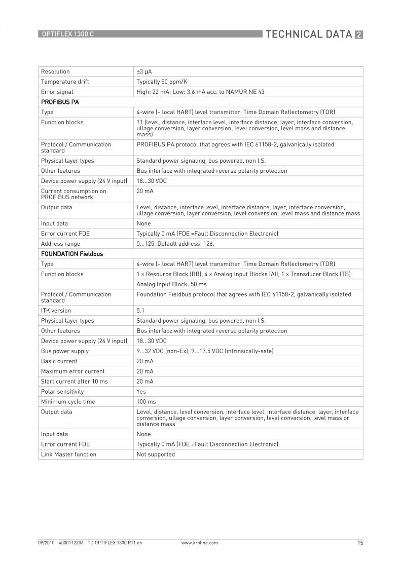
Resolution ±3 µA
Temperature drift Typically 50 ppm/K
Error signal High: 22 mA; Low: 3.6 mA acc. to NAMUR NE 43
PROFIBUS PAPROFIBUS PAPROFIBUS PAPROFIBUS PA
Type 4-wire (+ local HART) level transmitter; Time Domain Reflectometry (TDR)
Function blocks 11 (level, distance, interface level, interface distance, layer, interface conversion, ullage conversion, layer conversion, level conversion, level mass and distance mass)
Protocol / Communication standard
PROFIBUS PA protocol that agrees with IEC 61158-2, galvanically isolated
Physical layer types Standard power signaling, bus powered, non I.S.
Other features Bus interface with integrated reverse polarity protection
Device power supply (24 V input) 18...30 VDC
Current consumption on PROFIBUS network
20 mA
Output data Level, distance, interface level, interface distance, layer, interface conversion, ullage conversion, layer conversion, level conversion, level mass and distance mass
Input data None
Error current FDE Typically 0 mA (FDE =Fault Disconnection Electronic)
Address range 0...125. Default address: 126.
FOUNDATION FieldbusFOUNDATION FieldbusFOUNDATION FieldbusFOUNDATION Fieldbus
Type 4-wire (+ local HART) level transmitter; Time Domain Reflectometry (TDR)
Function blocks 1 × Resource Block (RB), 4 × Analog Input Blocks (AI), 1 × Transducer Block (TB)
Analog Input Block: 50 ms
Protocol / Communication standard
Foundation Fieldbus protocol that agrees with IEC 61158-2, galvanically isolated
ITK version 5.1
Physical layer types Standard power signaling, bus powered, non I.S.
Other features Bus interface with integrated reverse polarity protection
Device power supply (24 V input) 18...30 VDC
Bus power supply 9...32 VDC (non-Ex); 9...17.5 VDC (intrinsically-safe)
Basic current 20 mA
Maximum error current 20 mA
Start current after 10 ms 20 mA
Polar sensitivity Yes
Minimum cycle time 100 ms
Output data Level, distance, level conversion, interface level, interface distance, layer, interface conversion, ullage conversion, layer conversion, level conversion, level mass or distance mass
Input data None
Error current FDE Typically 0 mA (FDE =Fault Disconnection Electronic)
Link Master function Not supported
2 TECHNICAL DATA
16
OPTIFLEX 1300 C
www.krohne.com 09/2010 - 4000112206 - TD OPTIFLEX 1300 R11 en
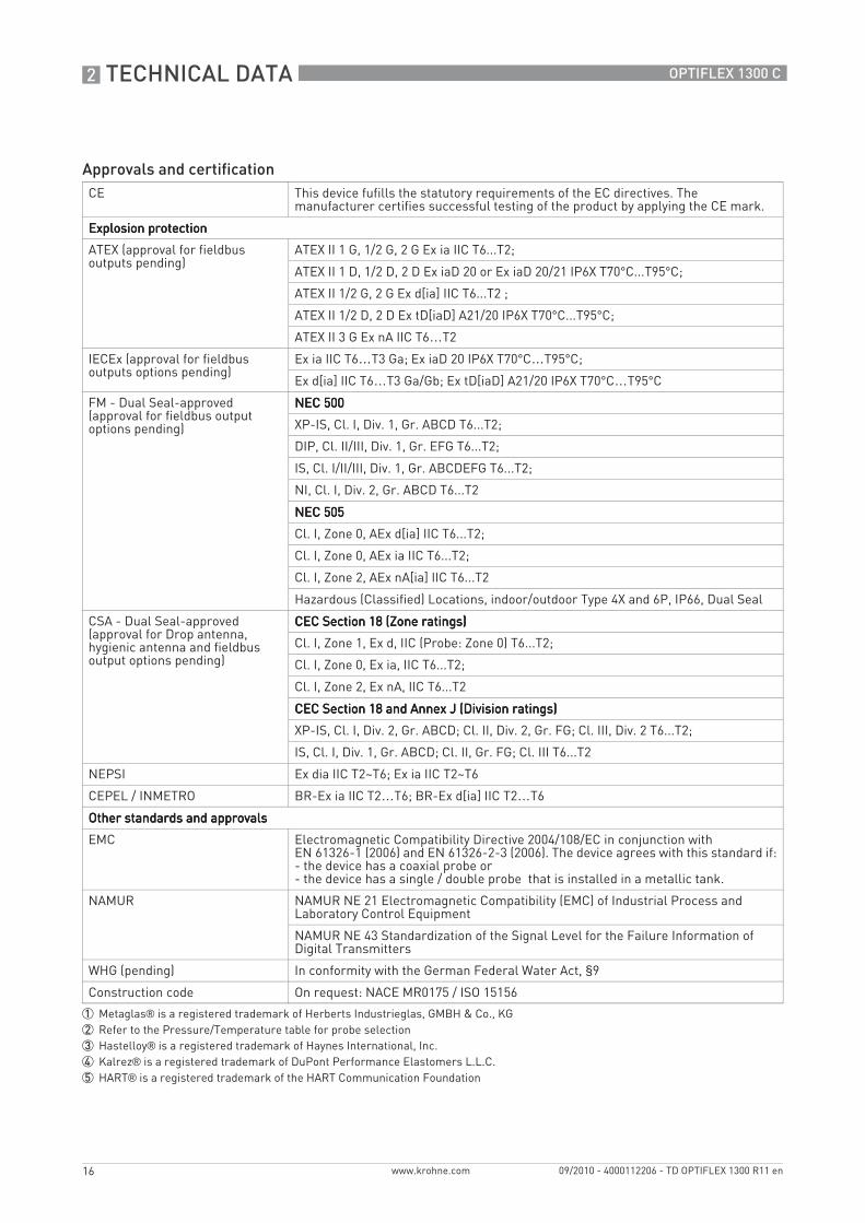
Approvals and certificationCE This device fufills the statutory requirements of the EC directives. The
manufacturer certifies successful testing of the product by applying the CE mark.
Explosion protectionExplosion protectionExplosion protectionExplosion protection
ATEX (approval for fieldbus outputs pending)
ATEX II 1 G, 1/2 G, 2 G Ex ia IIC T6...T2;
ATEX II 1 D, 1/2 D, 2 D Ex iaD 20 or Ex iaD 20/21 IP6X T70°C...T95°C;
ATEX II 1/2 G, 2 G Ex d[ia] IIC T6...T2 ;
ATEX II 1/2 D, 2 D Ex tD[iaD] A21/20 IP6X T70°C...T95°C;
ATEX II 3 G Ex nA IIC T6…T2
IECEx (approval for fieldbus outputs options pending)
Ex ia IIC T6…T3 Ga; Ex iaD 20 IP6X T70°C…T95°C;
Ex d[ia] IIC T6…T3 Ga/Gb; Ex tD[iaD] A21/20 IP6X T70°C…T95°C
FM - Dual Seal-approved (approval for fieldbus output options pending)
NEC 500NEC 500NEC 500NEC 500
XP-IS, Cl. I, Div. 1, Gr. ABCD T6...T2;
DIP, Cl. II/III, Div. 1, Gr. EFG T6...T2;
IS, Cl. I/II/III, Div. 1, Gr. ABCDEFG T6...T2;
NI, Cl. I, Div. 2, Gr. ABCD T6...T2
NEC 505NEC 505NEC 505NEC 505
Cl. I, Zone 0, AEx d[ia] IIC T6...T2;
Cl. I, Zone 0, AEx ia IIC T6...T2;
Cl. I, Zone 2, AEx nA[ia] IIC T6...T2
Hazardous (Classified) Locations, indoor/outdoor Type 4X and 6P, IP66, Dual Seal
CSA - Dual Seal-approved (approval for Drop antenna, hygienic antenna and fieldbus output options pending)
CEC Section 18 (Zone ratings)CEC Section 18 (Zone ratings)CEC Section 18 (Zone ratings)CEC Section 18 (Zone ratings)
Cl. I, Zone 1, Ex d, IIC (Probe: Zone 0) T6...T2;
Cl. I, Zone 0, Ex ia, IIC T6...T2;
Cl. I, Zone 2, Ex nA, IIC T6...T2
CEC Section 18 and Annex J (Division ratings)CEC Section 18 and Annex J (Division ratings)CEC Section 18 and Annex J (Division ratings)CEC Section 18 and Annex J (Division ratings)
XP-IS, Cl. I, Div. 2, Gr. ABCD; Cl. II, Div. 2, Gr. FG; Cl. III, Div. 2 T6...T2;
IS, Cl. I, Div. 1, Gr. ABCD; Cl. II, Gr. FG; Cl. III T6...T2
NEPSI Ex dia IIC T2~T6; Ex ia IIC T2~T6
CEPEL / INMETRO BR-Ex ia IIC T2…T6; BR-Ex d[ia] IIC T2…T6
Other standards and approvalsOther standards and approvalsOther standards and approvalsOther standards and approvals
EMC Electromagnetic Compatibility Directive 2004/108/EC in conjunction with EN 61326-1 (2006) and EN 61326-2-3 (2006). The device agrees with this standard if:- the device has a coaxial probe or- the device has a single / double probe that is installed in a metallic tank.
NAMUR NAMUR NE 21 Electromagnetic Compatibility (EMC) of Industrial Process and Laboratory Control Equipment
NAMUR NE 43 Standardization of the Signal Level for the Failure Information of Digital Transmitters
WHG (pending) In conformity with the German Federal Water Act, §9
Construction code On request: NACE MR0175 / ISO 15156
1 Metaglas® is a registered trademark of Herberts Industrieglas, GMBH & Co., KG2 Refer to the Pressure/Temperature table for probe selection3 Hastelloy® is a registered trademark of Haynes International, Inc.4 Kalrez® is a registered trademark of DuPont Performance Elastomers L.L.C.5 HART® is a registered trademark of the HART Communication Foundation

TECHNICAL DATA 2
17
OPTIFLEX 1300 C
www.krohne.com09/2010 - 4000112206 - TD OPTIFLEX 1300 R11 en
2.2 Application table for probe selection
Dou
ble
rod
Sing
le r
od
Sing
le r
od (s
egm
ente
d)
Coa
xial
Coa
xial
(seg
men
ted)
Dou
ble
cabl
e
Sing
le c
able
Ø8
mm
/ 0.
3¨
Sing
le c
able
Ø4
mm
/ 0.
15¨
Sing
le c
able
Ø2
mm
/ 0.
08¨
Maximum probe length, L4 m / 13 ft
6 m / 20 ft
8 m / 26 ft
35 m / 115 ft
LiquidsLiquid application
LPG, LNG 1 1
Highly viscous liquids
Highly crystallising liquids
Highly corrosive liquids
Foam
Agitated liquids 2 2 2 2 2
High-pressure applications 3 3 3 3 3 3 3 4
High-temperature applications 5
Spray in tank 1 1 1 1
Storage tanks
Installation in bypass chamber
Small diameter nozzles
Long nozzles
Stilling wells
Interface measurement 6 6
SolidsPowders 7
Granules, <5 mm / 0.1¨ 7
J standard J optional U on request
1 Install the device in a stilling well or a bypass chamber2 Use this probe with an anchor fitting. For more data, refer to the handbook.3 Max. pressure is 100 bar / 1450 psig. Refer to the pressure-temperature table for probe selection.4 Optional. Max. pressure is 300 bar / 4350 psig. Refer to the pressure-temperature table for probe selection.5 Optional. Max. temperature is 300°C / 570°F. Refer to the pressure-temperature table for probe selection.6 Max. length is 20 m / 65.5 ft, more on request7 Max. length is 10 m / 33 ft, more on request

2 TECHNICAL DATA
18
OPTIFLEX 1300 C
www.krohne.com 09/2010 - 4000112206 - TD OPTIFLEX 1300 R11 en
2.3 Pressure/temperature table for probe selection
Make sure that the transmitters are used within their operating limits.
Figure 2-1: Pressure/temperature table for probe selection
1 Process pressure, Ps [barg]2 Process connection temperature, T [°C]3 All probes4 High-Pressure (HP) version of the Ø2 mm single cable probe5 High-Temperature/High-Pressure (HT/HP) version of the Ø2 mm single cable probe6 High-Temperature (HT) version of the Ø2 mm single cable probe
Figure 2-2: Pressure/temperature table for probe selection
1 Process pressure, Ps [psig]2 Process connection temperature, T [°F]3 All probes4 High-Pressure (HP) version of the Ø0.08¨ single cable probe5 High-Temperature/High-Pressure (HT/HP) version of the Ø0.08¨ single cable probe6 High-Temperature (HT) version of the Ø0.08¨ single cable probe
��� � �� ��� ��� ��� ��� ����
���
���
������
�
��
�
�
��� � ��� ��� ��� ��� �� ����
����
����
��������
�
��
�
�
The minimum and maximum process connection temperature and the minimum and maximum process pressure also depends on the gasket material selected. Refer to "Technical data" on page 11.
TECHNICAL DATA 2
19
OPTIFLEX 1300 C
www.krohne.com09/2010 - 4000112206 - TD OPTIFLEX 1300 R11 en
2.4 Measurement limits
Measurement limits in mm and inches
80 is εr of water; 2.3 is εr of oil
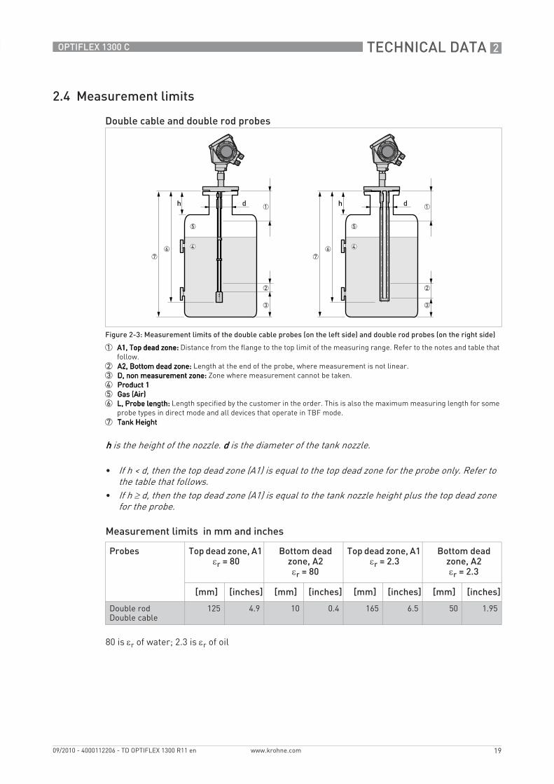
Double cable and double rod probes
Figure 2-3: Measurement limits of the double cable probes (on the left side) and double rod probes (on the right side)
1 A1, Top dead zone: A1, Top dead zone: A1, Top dead zone: A1, Top dead zone: Distance from the flange to the top limit of the measuring range. Refer to the notes and table that follow.
2 A2, Bottom dead zone: A2, Bottom dead zone: A2, Bottom dead zone: A2, Bottom dead zone: Length at the end of the probe, where measurement is not linear.3 D, non measurement zone: D, non measurement zone: D, non measurement zone: D, non measurement zone: Zone where measurement cannot be taken.4 Product 1Product 1Product 1Product 15 Gas (Air)Gas (Air)Gas (Air)Gas (Air)6 L, Probe length: L, Probe length: L, Probe length: L, Probe length: Length specified by the customer in the order. This is also the maximum measuring length for some
probe types in direct mode and all devices that operate in TBF mode.7 Tank HeightTank HeightTank HeightTank Height
hhhh is the height of the nozzle. dddd is the diameter of the tank nozzle.
• If h < d, then the top dead zone (A1) is equal to the top dead zone for the probe only. Refer to the table that follows.
• If h ≥ d, then the top dead zone (A1) is equal to the tank nozzle height plus the top dead zone for the probe.
Probes Top dead zone, A1 εr = 80
Bottom dead zone, A2 εr = 80
Top dead zone, A1 εr = 2.3
Bottom dead zone, A2 εr = 2.3
[mm] [inches] [mm] [inches] [mm] [inches] [mm] [inches]
Double rodDouble cable
125 4.9 10 0.4 165 6.5 50 1.95
2 TECHNICAL DATA
20
OPTIFLEX 1300 C
www.krohne.com 09/2010 - 4000112206 - TD OPTIFLEX 1300 R11 en
Measurement limits in mm and inches
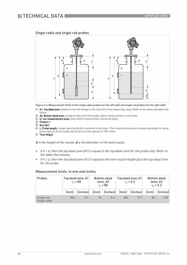
Single cable and single rod probes
Figure 2-4: Measurement limits of the single cable probes (on the left side) and single rod probes (on the right side)
1 A1, Top dead zone: A1, Top dead zone: A1, Top dead zone: A1, Top dead zone: Distance from the flange to the top limit of the measuring range. Refer to the notes and table that follow.
2 A2, Bottom dead zone: A2, Bottom dead zone: A2, Bottom dead zone: A2, Bottom dead zone: Length at the end of the probe, where measurement is not linear.3 D, non measurement zone: D, non measurement zone: D, non measurement zone: D, non measurement zone: Zone where measurement cannot be taken.4 Product 1Product 1Product 1Product 15 Gas (Air)Gas (Air)Gas (Air)Gas (Air)6 L, Probe length: L, Probe length: L, Probe length: L, Probe length: Length specified by the customer in the order. This is also the maximum measuring length for some
probe types in direct mode and all devices that operate in TBF mode.7 Tank HeightTank HeightTank HeightTank Height
hhhh is the height of the nozzle. dddd is the diameter of the tank nozzle.
• If h < d, then the top dead zone (A1) is equal to the top dead zone for the probe only. Refer to the table that follows.
• If h ≥ d, then the top dead zone (A1) is equal to the tank nozzle height plus the top dead zone for the probe.
Probes Top dead zone, A1 εr = 80
Bottom dead zone, A2 εr = 80
Top dead zone, A1 εr = 2.3
Bottom dead zone, A2 εr = 2.3
[mm] [inches] [mm] [inches] [mm] [inches] [mm] [inches]
Single rodSingle cable
200 7.9 10 0.4 250 9.9 50 1.95
TECHNICAL DATA 2
21
OPTIFLEX 1300 C
www.krohne.com09/2010 - 4000112206 - TD OPTIFLEX 1300 R11 en
Measurement limits in mm and inches
Coaxial probe
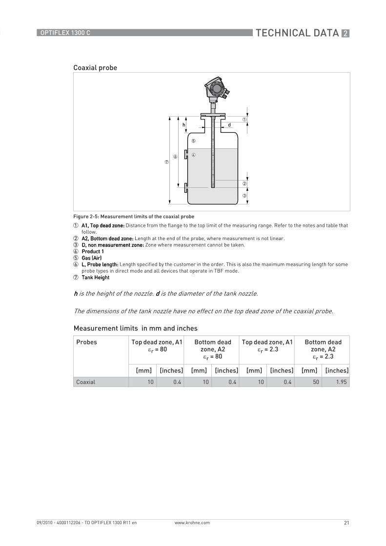
Figure 2-5: Measurement limits of the coaxial probe
1 A1, Top dead zone: A1, Top dead zone: A1, Top dead zone: A1, Top dead zone: Distance from the flange to the top limit of the measuring range. Refer to the notes and table that follow.
2 A2, Bottom dead zone: A2, Bottom dead zone: A2, Bottom dead zone: A2, Bottom dead zone: Length at the end of the probe, where measurement is not linear.3 D, non measurement zone: D, non measurement zone: D, non measurement zone: D, non measurement zone: Zone where measurement cannot be taken.4 Product 1Product 1Product 1Product 15 Gas (Air)Gas (Air)Gas (Air)Gas (Air)6 L, Probe length: L, Probe length: L, Probe length: L, Probe length: Length specified by the customer in the order. This is also the maximum measuring length for some
probe types in direct mode and all devices that operate in TBF mode.7 Tank HeightTank HeightTank HeightTank Height
hhhh is the height of the nozzle. dddd is the diameter of the tank nozzle.
The dimensions of the tank nozzle have no effect on the top dead zone of the coaxial probe.
Probes Top dead zone, A1 εr = 80
Bottom dead zone, A2 εr = 80
Top dead zone, A1 εr = 2.3
Bottom dead zone, A2 εr = 2.3
[mm] [inches] [mm] [inches] [mm] [inches] [mm] [inches]
Coaxial 10 0.4 10 0.4 10 0.4 50 1.95

2 TECHNICAL DATA
22
OPTIFLEX 1300 C
www.krohne.com 09/2010 - 4000112206 - TD OPTIFLEX 1300 R11 en
2.5 Dimensions and weights
Standard converterStandard converterStandard converterStandard converter
Figure 2-6: Standard converter
1 Converter (front view)2 Flange version for all probes except the Ø2 mm / 0.08¨ single cable probe (right side)3 Flange version for Ø2 mm / 0.08¨ single cable probe - High-Pressure (HP) version (right side)4 Flange version for Ø2 mm / 0.08¨ single cable probe - High-Temperature (HT) and High-Temperature/High-Pressure
(HT/HP) versions (right side)5 Thread version for all probes except the Ø2 mm / 0.08¨ single cable probe (right side)6 Thread version for Ø2 mm / 0.08¨ single cable probe - High-Pressure (HP) version (right side)7 Thread version for Ø2 mm / 0.08¨ single cable probe - High-Temperature (HT) and High-Temperature/High-Pressure
(HT/HP) versions (right side)
• Cable glands are delivered on demand with non-Ex, Ex i- and Ex d-approved devices.• Non-Ex and Ex i fittings are plastic and Ex d fittings are metallic. Non-Ex fittings are black
and Ex i fittings are blue. • The diameter of the outer sheath of the cable must be 6…12 mm or 0.2…0.5¨.• Cable glands for FM- or CSA-approved devices must be supplied by the customer.

TECHNICAL DATA 2
23
OPTIFLEX 1300 C
www.krohne.com09/2010 - 4000112206 - TD OPTIFLEX 1300 R11 en
Dimensions and weights in mm and kg
Dimensions and weights in inches and lb
Dimensions [mm] Weights [kg]
a b c d e f g h i
Converter 180 122 158.5 1821
170 197 - - - 3.3
Flange, single cable Ø2 - version HTor HT/HP
180 122 158.5 1821
170 197 59 3572
4502
6...15
Flange, single cable Ø2 - version HP
180 122 158.5 1821
170 197 160 2562
3492
5...14
Flange, all other probes 180 122 158.5 1821
170 197 123 3202
3572
4…12
Thread, single cable Ø2 - version HT or HT/HP
180 180 158.5 1821
170 197 144 3412
3782
4.5
Thread, single cable Ø2 - version HP
180 180 158.5 1821
170 197 43 2402
2772
4
Thread, all other probes 180 122 158.5 1821
170 197 95 2922
3292
3
1 This dimension is subject to the size of the cable gland used2 With 30 kV ESD protection option: add 99 mm to this dimension. With Metaglas® option: add 43 mm to this dimension.
Dimensions [inches] Weights [lb]
a b c d e f g h i
Converter 7.1 4.8 6.2 7.21
6.7 7.8 - - - 7.3
Flange, single cable Ø0.08 - version HTor HT/HP
7.1 4.8 6.2 7.21
6.7 7.8 2.3 142
17.72
13.2...33.1
Flange, single cable Ø0.08 - version HP
7.1 4.8 6.2 7.21
6.7 7.8 6.3 10.12
13.72
11...30.9
Flange, all other probes 7.1 4.8 6.2 7.21
6.7 7.8 4.8 12.62
14.12
8.8...26.5
Thread, single cable Ø0.08 - version HT or HT/HP
7.1 4.8 6.2 7.21
6.7 7.8 5.7 13.42
14.92
9.9
Thread, single cable Ø0.08 - version HP
7.1 4.8 6.2 7.21
6.7 7.8 1.7 9.42
10.92
8.8
Thread, all other probes 7.1 4.8 6.2 7.21
6.7 7.8 3.7 11.52
12.92
6.6
1 This dimension is subject to the size of the cable gland used2 With 30 kV ESD protection option: add 3.9¨ to this dimension. With Metaglas® option: add 1.7¨ to this dimension.
2 TECHNICAL DATA
24
OPTIFLEX 1300 C
www.krohne.com 09/2010 - 4000112206 - TD OPTIFLEX 1300 R11 en
Note: Note: Note: Note:
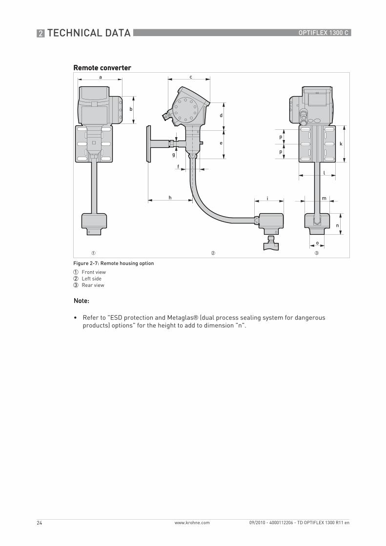
• Refer to "ESD protection and Metaglas® (dual process sealing system for dangerous products) options" for the height to add to dimension "n".
Remote converterRemote converterRemote converterRemote converter
Figure 2-7: Remote housing option
1 Front view2 Left side3 Rear view
TECHNICAL DATA 2
25
OPTIFLEX 1300 C
www.krohne.com09/2010 - 4000112206 - TD OPTIFLEX 1300 R11 en
Dimensions and weights in mm and kg
Dimensions and weights in inches and lb
Remote version limitsRemote version limitsRemote version limitsRemote version limits
• For interface and solid (powder, granulate) applications, the maximum extension length is 4.5 m / 14.8 ft.
• For liquid level applications, the maximum measuring range is reduced according to the length of the coaxial cable between the flange and the converter (extension length).
ApplicationsApplicationsApplicationsApplications
• Tanks which are subjected to a lot of vibration• Limited space on the top of the tank or limited access (due to the size of the compact
converter)• Remote display at the bottom of the tank
Dimensions [mm] Weights [kg]
a b c d e f g h i k l m n o p
Remote version
180 109 165 193 98.5 58 21 183 117 150 150.4 100 86 58 60 6.6...12.8 1
1 Wall bracket (1.4 kg) + converter support (1.5 kg) + remote probe converter (2.7 kg) + flexible conduit (2 m: 1 kg; 4.5 m: 2.25 kg; 9.5 m: 4.75 kg; 14.5 m: 7.25 kg)
Dimensions [inches] Weights [lb]
a b c d e f g h i k l m n o p
Remote version
7.09 4.29 6.50 7.60 3.88 2.28 0.83 7.20 4.60 5.91 5.92 3.94 3.39 2.28 2.36 14.6...28.3 1
1 Wall bracket (3.1 lb) + converter support (3.3 lb) + remote probe converter (6.0 lb) + flexible conduit (6.6 ft: 2.2 lb; 14.8 ft: 5.0 lb; 31.2 ft: 10.5 lb; 47.6 ft: 16.0 lb)
Extension length Max. measuring range (or sensor length, L)
[m] [ft] [m] [ft]
2 6.6 30 98
4.5 14.8 25 82
9.5 31.2 15 29
14.5 47.6 5 16.4
2 TECHNICAL DATA
26
OPTIFLEX 1300 C
www.krohne.com 09/2010 - 4000112206 - TD OPTIFLEX 1300 R11 en
Dimensions and weights in mm and kg
Dimensions and weights in inches and lb
Weather protection option
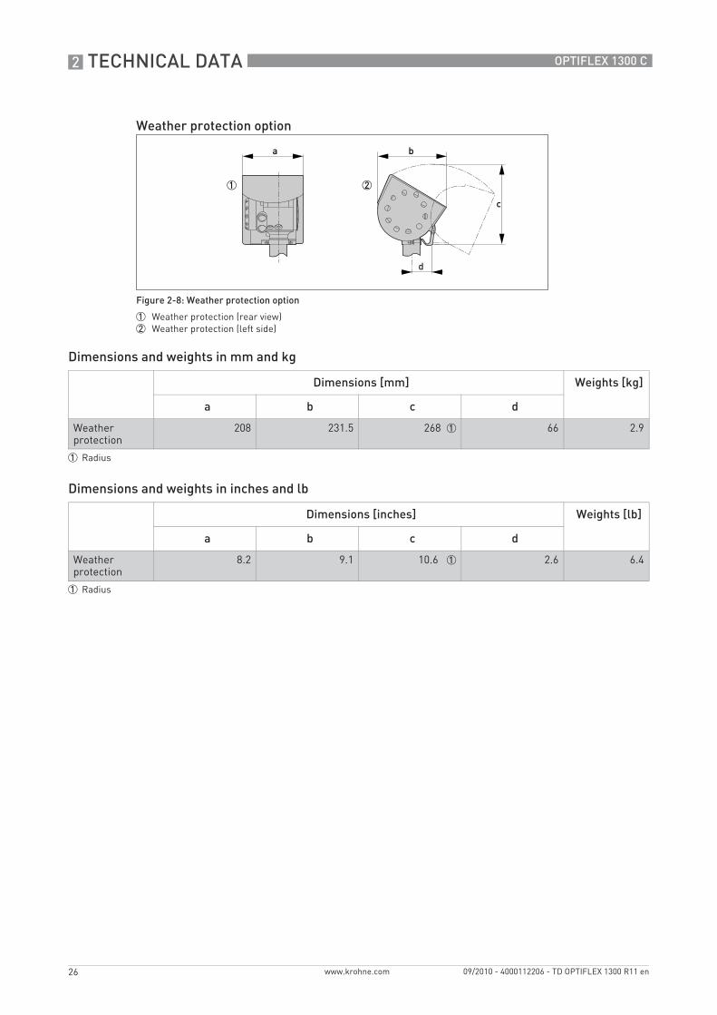
Figure 2-8: Weather protection option
1 Weather protection (rear view)2 Weather protection (left side)
Dimensions [mm] Weights [kg]
a b c d
Weather protection
208 231.5 268 1 66 2.9
1 Radius
Dimensions [inches] Weights [lb]
a b c d
Weather protection
8.2 9.1 10.6 1 2.6 6.4
1 Radius
TECHNICAL DATA 2
27
OPTIFLEX 1300 C
www.krohne.com09/2010 - 4000112206 - TD OPTIFLEX 1300 R11 en
Special options: Dimensions and weights in mm and kg
Special options: Dimensions and weights in inches and lb
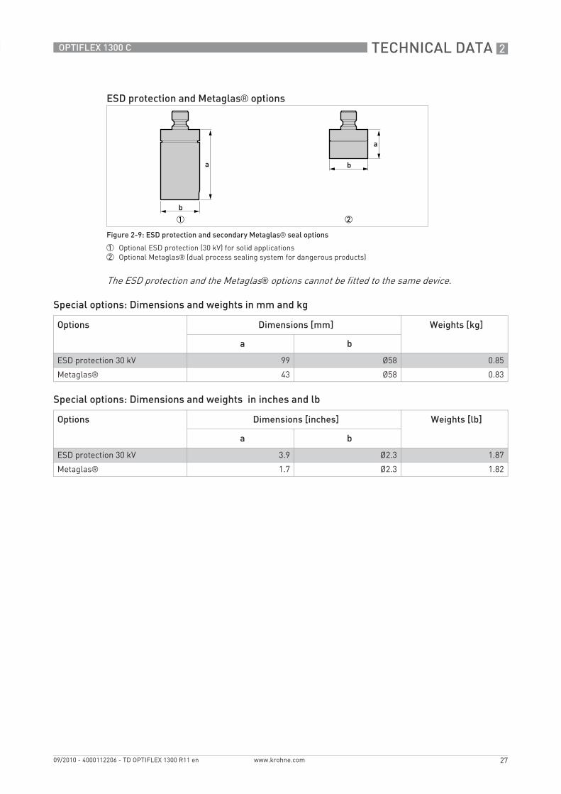
ESD protection and Metaglas® options
Figure 2-9: ESD protection and secondary Metaglas® seal options
1 Optional ESD protection (30 kV) for solid applications2 Optional Metaglas® (dual process sealing system for dangerous products)
The ESD protection and the Metaglas® options cannot be fitted to the same device.
Options Dimensions [mm] Weights [kg]
a b
ESD protection 30 kV 99 Ø58 0.85
Metaglas® 43 Ø58 0.83
Options Dimensions [inches] Weights [lb]
a b
ESD protection 30 kV 3.9 Ø2.3 1.87
Metaglas® 1.7 Ø2.3 1.82
2 TECHNICAL DATA
28
OPTIFLEX 1300 C
www.krohne.com 09/2010 - 4000112206 - TD OPTIFLEX 1300 R11 en
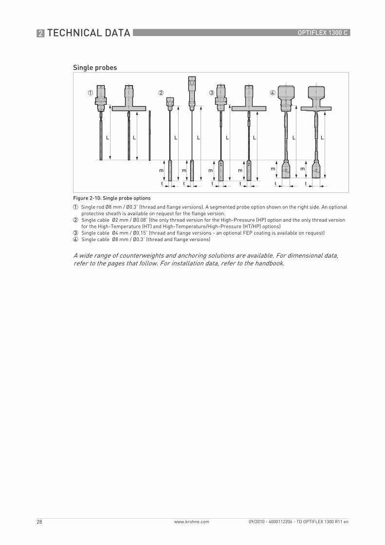
Single probes
Figure 2-10: Single probe options
1 Single rod Ø8 mm / Ø0.3¨ (thread and flange versions). A segmented probe option shown on the right side. An optional protective sheath is available on request for the flange version.
2 Single cable Ø2 mm / Ø0.08¨ (the only thread version for the High-Pressure (HP) option and the only thread version for the High-Temperature (HT) and High-Temperature/High-Pressure (HT/HP) options)
3 Single cable Ø4 mm / Ø0.15¨ (thread and flange versions - an optional FEP coating is available on request)4 Single cable Ø8 mm / Ø0.3¨ (thread and flange versions)
L L L L L L
m m m m m m
L L
A wide range of counterweights and anchoring solutions are available. For dimensional data, refer to the pages that follow. For installation data, refer to the handbook.
TECHNICAL DATA 2
29
OPTIFLEX 1300 C
www.krohne.com09/2010 - 4000112206 - TD OPTIFLEX 1300 R11 en
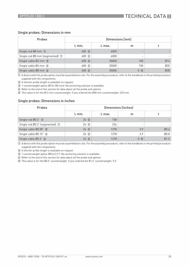
Single probes: Dimensions in mm
Single probes: Dimensions in inches
Probes Dimensions [mm]
L min. L max. m t
Single rod Ø8 mm 1 600 2 4000 - -
Single rod Ø8 mm (segmented) 1 600 2 6000 - -
Single cable Ø2 mm 3 600 2 35000 100 Ø14
Single cable Ø4 mm 4 600 2 35000 100 Ø20
Single cable Ø8 mm 4 600 2 35000 0 5 Ø38
1 A device with this probe option must be assembled on site. For the assembly procedure, refer to the handbook or the printed procedure supplied with the components.
2 A shorter probe length is available on request3 1 counterweight option (Ø14×100 mm). No anchoring solution is available.4 Refer to the end of this section for data about all the probe end options5 This value is for the Ø12 mm counterweight. If you ordered the Ø38 mm counterweight: 245 mm
Probes Dimensions [inches]
L min. L max. m t
Single rod Ø0.3¨ 1 24 2 158 - -
Single rod Ø0.3¨ (segmented) 1 24 2 236 - -
Single cable Ø0.08¨ 3 24 2 1378 3.9 Ø0.6
Single cable Ø0.15¨ 4 24 2 1378 3.9 Ø0.8
Single cable Ø0.3¨ 4 24 2 1378 0 5 Ø1.5
1 A device with this probe option must be assembled on site. For the assembly procedure, refer to the handbook or the printed procedure supplied with the components.
2 A shorter probe length is available on request3 1 counterweight option (Ø0.6×3.9¨). No anchoring solution is available.4 Refer to the end of this section for data about all the probe end options5 This value is for the Ø0.5¨ counterweight. If you ordered the Ø1.5¨ counterweight: 9.6¨

2 TECHNICAL DATA
30
OPTIFLEX 1300 C
www.krohne.com 09/2010 - 4000112206 - TD OPTIFLEX 1300 R11 en
Double probes
Figure 2-11: Double probe options
1 Double rod Ø8 mm / Ø0.3¨ (thread and flange versions)2 Double cable Ø4 mm / Ø0.15¨ (thread and flange versions)3 Coaxial Ø22 mm / Ø0.9¨ (thread and flange versions)
A wide range of counterweights and anchoring solutions are available. For dimensional data, refer to the pages that follow. For installation data, refer to the handbook.

TECHNICAL DATA 2
31
OPTIFLEX 1300 C
www.krohne.com09/2010 - 4000112206 - TD OPTIFLEX 1300 R11 en
Double probes: Dimensions in mm
Double probes: Dimensions in inches
Probes Dimensions [mm]
L min. L max. q t
Double rod Ø8 mm 1000 1 4000 - 25
Double cable Ø4 mm 2 1000 1 8000 60 Ø38
Coaxial Ø22 mm 500 1 6000 - -
Coaxial Ø22 mm (segmented) 3 500 1 6000 - Ø28
1 A shorter probe length is available on request2 Refer to the end of this section for data about all the probe end options3 A device with this probe option must be assembled on site. For the assembly procedure, refer to the handbook or the printed procedure
supplied with the components.
Probes Dimensions [inches]
L min. L max. q t
Double rod Ø0.3¨ 40 1 158 - 1.0
Double cable Ø0.15¨ 2 40 1 315 2.4 Ø1.5
Coaxial Ø0.9¨ 20 1 236 - -
Coaxial Ø0.9¨ (segmented) 3 20 1 236 - Ø1.1
1 A shorter probe length is available on request2 Refer to the end of this section for data about all the probe end options3 A device with this probe option must be assembled on site. For the assembly procedure, refer to the handbook or the printed procedure
supplied with the components.

2 TECHNICAL DATA
32
OPTIFLEX 1300 C
www.krohne.com 09/2010 - 4000112206 - TD OPTIFLEX 1300 R11 en
Dimensions in mm
Dimensions in inches
Probe end options for cable probes: single cable Ø4 mm/0.15¨
Figure 2-12: Probe end options for cable probes: single cable Ø4 mm/0.15¨
1 Standard counterweight2 Threaded end3 Crimped end4 Open end5 Turnbuckle6 Chuck
nn
t t n
n n
t
t
v
1 2 3 4 5 6
Probe end type Dimensions [mm]
n t v
Counterweight 100 Ø20 -
Threaded end 70 M8 -
Crimped end 55 Ø8 -
Open end - - -
Turnbuckle 172 1 11 Ø6
Chuck 300 - -
1 Minimum length
Probe end type Dimensions [inches]
n t v
Counterweight 3.9 Ø0.8 -
Threaded end 2.8 M8 -
Crimped end 2.2 Ø0.3 -
Open end - - -
Turnbuckle 6.8 1 0.4 Ø0.2
Chuck 11.8 - -
1 Minimum length
TECHNICAL DATA 2
33
OPTIFLEX 1300 C
www.krohne.com09/2010 - 4000112206 - TD OPTIFLEX 1300 R11 en
Dimensions in mm
Dimensions in inches
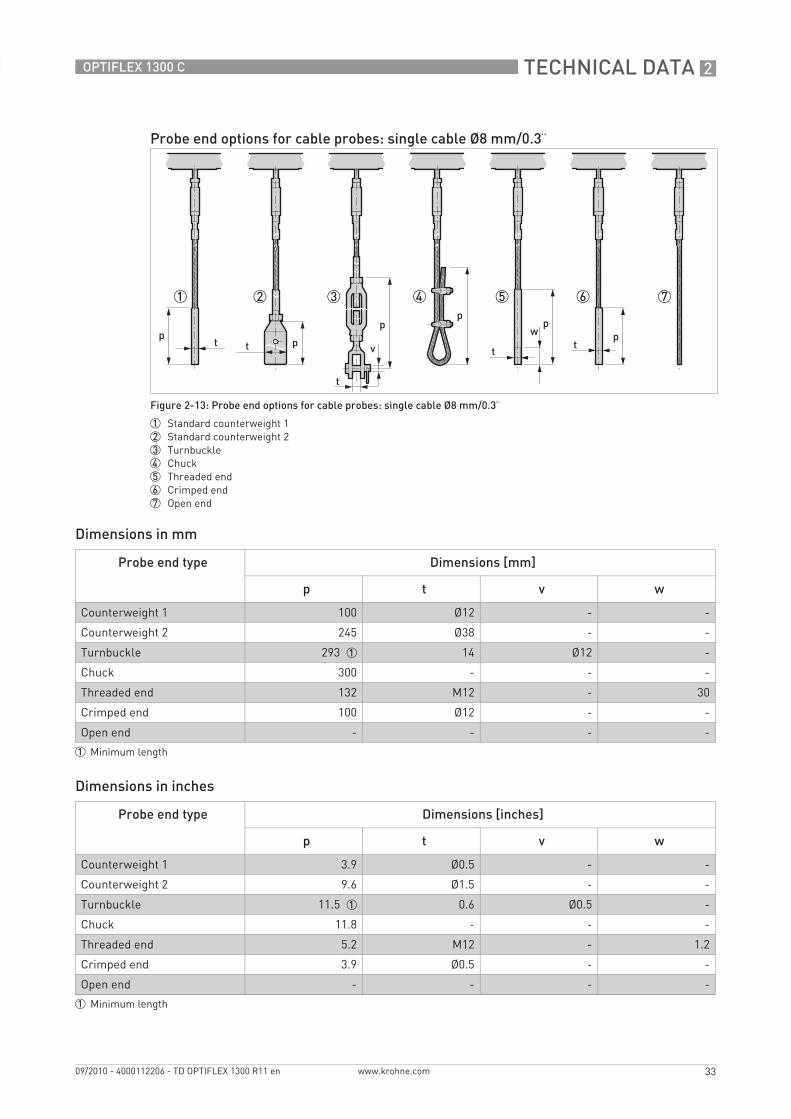
Probe end options for cable probes: single cable Ø8 mm/0.3¨
Figure 2-13: Probe end options for cable probes: single cable Ø8 mm/0.3¨
1 Standard counterweight 12 Standard counterweight 23 Turnbuckle4 Chuck5 Threaded end6 Crimped end7 Open end
t
t t ttv
pp
pp
ppw
1 2 3 4 5 6 7
Probe end type Dimensions [mm]
p t v w
Counterweight 1 100 Ø12 - -
Counterweight 2 245 Ø38 - -
Turnbuckle 293 1 14 Ø12 -
Chuck 300 - - -
Threaded end 132 M12 - 30
Crimped end 100 Ø12 - -
Open end - - - -
1 Minimum length
Probe end type Dimensions [inches]
p t v w
Counterweight 1 3.9 Ø0.5 - -
Counterweight 2 9.6 Ø1.5 - -
Turnbuckle 11.5 1 0.6 Ø0.5 -
Chuck 11.8 - - -
Threaded end 5.2 M12 - 1.2
Crimped end 3.9 Ø0.5 - -
Open end - - - -
1 Minimum length
2 TECHNICAL DATA
34
OPTIFLEX 1300 C
www.krohne.com 09/2010 - 4000112206 - TD OPTIFLEX 1300 R11 en
Dimensions in mm
Dimensions in inches
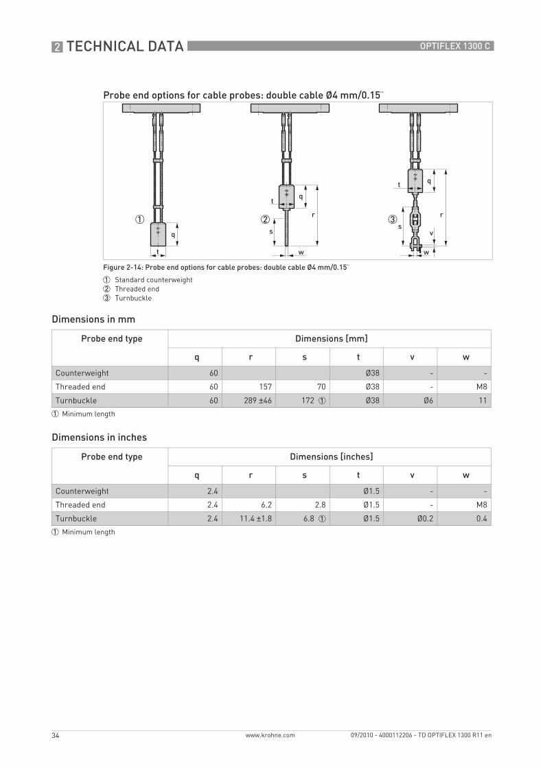
Probe end options for cable probes: double cable Ø4 mm/0.15¨
Figure 2-14: Probe end options for cable probes: double cable Ø4 mm/0.15¨
1 Standard counterweight2 Threaded end3 Turnbuckle
1 2 3
q
t
qt
t
r
q
r
ss
v
w w
Probe end type Dimensions [mm]
q r s t v w
Counterweight 60 Ø38 - -
Threaded end 60 157 70 Ø38 - M8
Turnbuckle 60 289 ±46 172 1 Ø38 Ø6 11
1 Minimum length
Probe end type Dimensions [inches]
q r s t v w
Counterweight 2.4 Ø1.5 - -
Threaded end 2.4 6.2 2.8 Ø1.5 - M8
Turnbuckle 2.4 11.4 ±1.8 6.8 1 Ø1.5 Ø0.2 0.4
1 Minimum length

TECHNICAL DATA 2
35
OPTIFLEX 1300 C
www.krohne.com09/2010 - 4000112206 - TD OPTIFLEX 1300 R11 en
Probe weights
Probes Min. process connection size Weights
Thread Flange [kg/m] [lb/ft]
Single cable Ø2 mm / 0.08¨ G ½A; ½ NPTF DN25 in PN16, PN40, PN63 or PN100; 1¨ in 150 lb, 600 lb, 900 lb, 1500 lb or 2500 lb; 1½¨ in 300 lb
0.016 0.01
Single cable Ø4 mm / 0.15¨ G ¾A; ¾ NPT DN25 in PN16, PN40, PN63 or PN100; 1¨ in 150 lb, 600 lb, 900 lb or 1500 lb; 1½¨ in 300 lb
0.12 0.08
Single cable Ø8 mm / 0.3¨ G 1½A; 1½ NPT DN40 in PN16, PN40, PN63 or PN100; 1½¨ in 150 lb, 300 lb, 600 lb, 900 lb or 1500 lb
0.41 0.28
Double cable Ø4 mm / 0.15¨ G 1½A; 1½ NPT DN50 in PN16, PN40, PN63 or PN100; 2¨ in 150 lb, 300 lb, 600 lb, 900 lb or 1500 lb
0.24 0.16
Single rod Ø8 mm / 0.3¨ G ¾A; ¾ NPT DN25 in PN16, PN40, PN63 or PN100; 1¨ in 150 lb, 600 lb, 900 lb or 1500 lb; 1½¨ in 300 lb
0.41 0.28
Double rod Ø8 mm / 0.3¨ G 1½A; 1½ NPT DN50 in PN16, PN40, PN63 or PN100; 2¨ in 150 lb, 300 lb, 600 lb, 900 lb or 1500 lb
0.82 0.56
Coaxial Ø22 mm / 0.9¨ G ¾A; ¾ NPT DN25 in PN16, PN40, PN63 or PN100; 1¨ in 150 lb, 600 lb, 900 lb or 1500 lb; 1½¨ in 300 lb
0.79 0.53

3 INSTALLATION
36
OPTIFLEX 1300 C
www.krohne.com 09/2010 - 4000112206 - TD OPTIFLEX 1300 R11 en
3.1 Intended use
This TDR level transmitter measures distance, level, mass and volume of liquids, pastes, slurries, granulates and powders. It can also measure level and interface of liquids at the same time.
It can be installed on tanks, silos and open pits.
3.2 Pre-installation requirements
• Make sure that there is sufficent space on all sides.• Protect the signal converter from direct sunlight. If necessary, install the weather protection
accessory.• Do not subject the signal converter to heavy vibrations. The devices are tested for vibration
and agree with EN 50178 and IEC 60068-2-6.
3.3 How to prepare the tank before you install the device
3.3.1 General information for nozzles
Obey the precautions that follow to make sure that the device is correctly installed.
To avoid measuring errors and device malfunction, obey these precautions.
Follow these recommendations to make sure that the device measures correctly.
Figure 3-1: Recommended nozzle dimensions
1 Recommended conditions: h ≤ d, where h is the height of the tank nozzle and d is the diameter of the tank nozzle.2 The end of the nozzle must not have an extension into the tank. Do not install the device on a high nozzle.
If the device is installed on a high nozzle, make sure that the probe does not touch the side of the nozzle (attach the probe end, ...).
It is possible to measure in these conditions with a minimum top dead zone. Use the snapshot function to filter the parasite signals from long nozzles. For more data, refer to the Handbook.

INSTALLATION 3
37
OPTIFLEX 1300 C
www.krohne.com09/2010 - 4000112206 - TD OPTIFLEX 1300 R11 en
Figure 3-2: Sockets for threaded process connections
1 Recommended installation2 The end of the socket must not have an extension into the tank
1 2
Do not put the process connection near to the product inlet. If the product that enters the tank touches the probe, the device will measure incorrectly.
Figure 3-3: Do not put the device near to a product inlet
1 The device is in the correct position.2 The device is too near to the product inlet.3 If it is not possible to put the device in the recommended position, install a deflector pipe.
1 2
3 3

3 INSTALLATION
38
OPTIFLEX 1300 C
www.krohne.com 09/2010 - 4000112206 - TD OPTIFLEX 1300 R11 en
3.3.2 Installation requirements for concrete roofs
Figure 3-4: How to prevent build up of product around the process connection
1 If product particles are likely to collect in holes, a nozzle is not recommended.2 Attach the flange directly to the tank.3 Use a thread connection to attach the device to the tank.
Figure 3-5: Installation on a concrete roof
1 The diameter, d, of the hole must be greater than the thickness, t, of the concrete.2 If the thickness, t, of the concrete is greater than the diameter, d, of the hole, install the device in a recess.

INSTALLATION 3
39
OPTIFLEX 1300 C
www.krohne.com09/2010 - 4000112206 - TD OPTIFLEX 1300 R11 en
3.4 Installation recommendations for liquids
3.4.1 General requirements
Figure 3-6: Installation recommendations for liquids
1 h ≤ d, where h is the height of the tank nozzle and d is its diameter.2 Make sure that the probe does not touch the nozzle. Attach the probe if the liquid is turbulent.3 The electromagnetic (EM) field generated by the device. It has a radius of Rmin. Make sure that the EM field is clear of
objects and product flow. Refer to the table that follows.4 If there are too many objects in the tank, install a bypass chamber or stilling well.5 Keep the probe straight. If the probe is too long, shorten the probe length. Make sure that the device is configured with
the new probe length. For more data on the procedure, refer to the handbook.6 Empty space necessary for double probes. Refer to the table that follows.7 Empty space necessary for single probes. Refer to the table that follows.
If your device has a coaxial probe, you can ignore these installation recommendations.
Install coaxial probes in clean liquids that are not too viscous.
If the device has to measure the level of dangerous products (ammonia etc.), we recommend that you use a device with the Metaglas® option.
3 INSTALLATION
40
OPTIFLEX 1300 C
www.krohne.com 09/2010 - 4000112206 - TD OPTIFLEX 1300 R11 en
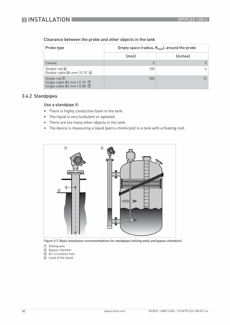
Clearance between the probe and other objects in the tank
3.4.2 Standpipes
Use a standpipe if:• There is highly conductive foam in the tank.• The liquid is very turbulent or agitated.• There are too many other objects in the tank.• The device is measuring a liquid (petro-chemicals) in a tank with a floating roof.
Probe type Empty space (radius, Rmin), around the probe
[mm] [inches]
Coaxial 0 0
Double rod 6Double cable Ø4 mm / 0.15¨ 6
100 4
Single rod 7Single cable Ø4 mm / 0.15¨ 7Single cable Ø2 mm / 0.08¨ 7
300 12
Figure 3-7: Basic installation recommendations for standpipes (stilling wells and bypass chambers)
1 Stilling well2 Bypass chamber3 Air circulation hole4 Level of the liquid
INSTALLATION 3
41
OPTIFLEX 1300 C
www.krohne.com09/2010 - 4000112206 - TD OPTIFLEX 1300 R11 en
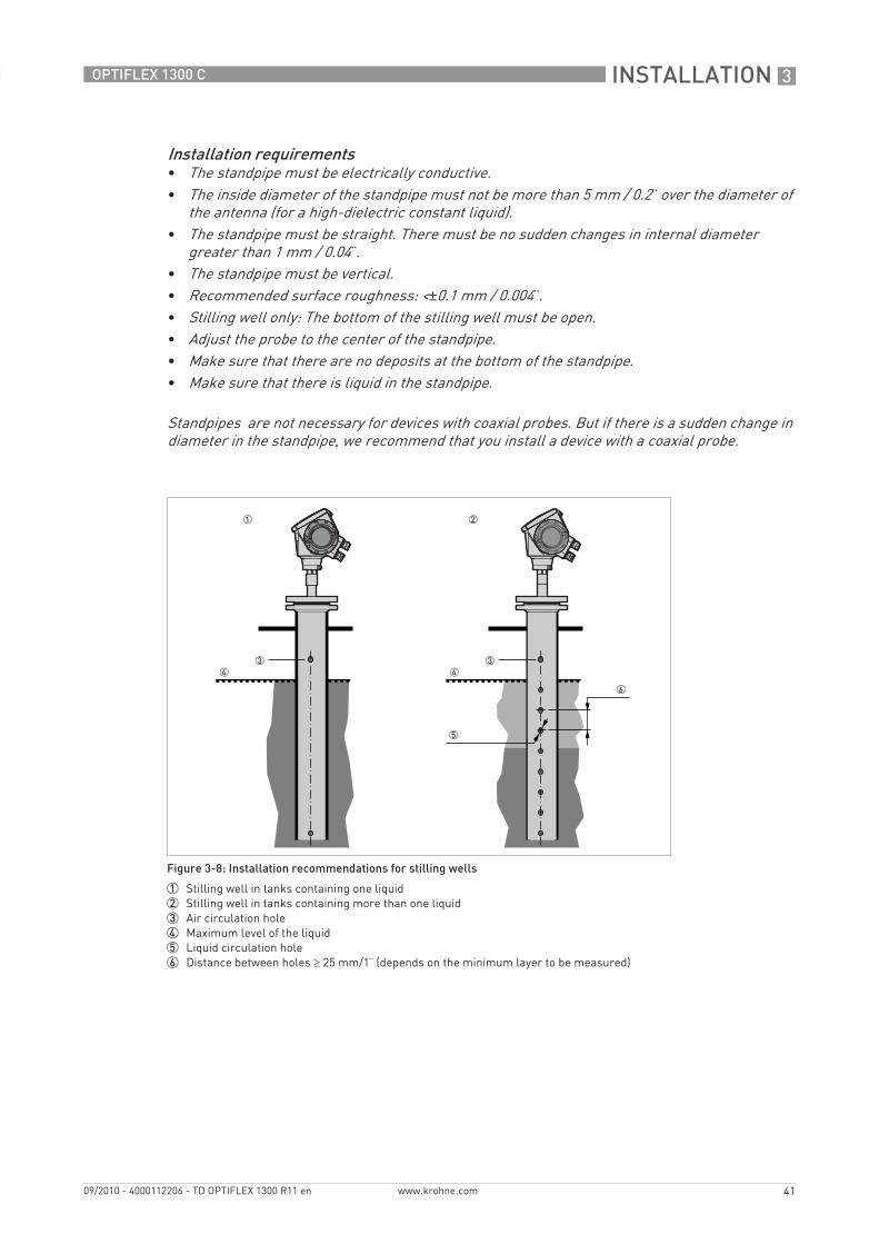
Installation requirements• The standpipe must be electrically conductive.• The inside diameter of the standpipe must not be more than 5 mm / 0.2¨ over the diameter of
the antenna (for a high-dielectric constant liquid).• The standpipe must be straight. There must be no sudden changes in internal diameter
greater than 1 mm / 0.04¨.• The standpipe must be vertical.• Recommended surface roughness: <±0.1 mm / 0.004¨.• Stilling well only: The bottom of the stilling well must be open.• Adjust the probe to the center of the standpipe.• Make sure that there are no deposits at the bottom of the standpipe.• Make sure that there is liquid in the standpipe.
Standpipes are not necessary for devices with coaxial probes. But if there is a sudden change in diameter in the standpipe, we recommend that you install a device with a coaxial probe.
Figure 3-8: Installation recommendations for stilling wells
1 Stilling well in tanks containing one liquid2 Stilling well in tanks containing more than one liquid3 Air circulation hole4 Maximum level of the liquid5 Liquid circulation hole6 Distance between holes ≥ 25 mm/1¨ (depends on the minimum layer to be measured)

3 INSTALLATION
42
OPTIFLEX 1300 C
www.krohne.com 09/2010 - 4000112206 - TD OPTIFLEX 1300 R11 en
Installation in tanks containing one liquid and foam• Drill a pressure equalization hole in the stilling well above the maximum level.• Deburr the hole.• If the probe has a counterweight, make sure that there is enough space between the
counterweight and the wall of the stilling well.
Installation in tanks containing more than one liquid• Drill a pressure equalization hole in the stilling well above the maximum level of the top liquid.• Drill more holes along the length of the stilling well. Distance between holes ≥ 25 mm / 1¨
(depends on the minimum layer to be measured)i These holes help the liquids to move freely.
• Deburr the holes.• If the probe has a counterweight, make sure that there is enough space between the
counterweight and the wall of the stilling well.
Floating roofsIf the device is for a tank with a floating roof, install it in a stilling well.
Figure 3-9: Floating roofs
1 Sediment2 Support fixtures3 Stilling well4 Floating roof5 Product6 Tank

INSTALLATION 3
43
OPTIFLEX 1300 C
www.krohne.com09/2010 - 4000112206 - TD OPTIFLEX 1300 R11 en
Installation on tanks containing one liquid and foam• The bypass chamber must have a process connection that is above the maximum level of
liquid.• The bypass chamber must have a process connection that is below the lowest measured level
of liquid.
Installation on tanks containing more than one liquid• The bypass chamber must have a process connection that is above the maximum level of
liquid.• The bypass chamber must have a process connection that is below the lowest measured level
of liquid.• There must be more process connections along the length of the bypass chamber. These
must have a minimum diameter of 25 mm / 1¨ with a minimum distance of 100 mm / 4¨ between the holes.
• If the probe has a counterweight, make sure that there is enough space between the counterweight and the wall of the stilling well.
• If the interface liquid does not have a layer of air above it, fit a vent at the top of the bypass chamber. Refer to the illustration that follows:
Bypass chamber - general notes
Figure 3-10: Installation recommendations for bypass chambers
1 Bypass chamber for tanks that contain one liquid2 Bypass chamber for tanks that contain more than one liquid3 Distance between holes ≤ minimum level of each liquid in the tank4 Additional process connection
2
3 INSTALLATION
44
OPTIFLEX 1300 C
www.krohne.com 09/2010 - 4000112206 - TD OPTIFLEX 1300 R11 en
3.5 Installation recommendations for solids
3.5.1 Nozzles on conical silos
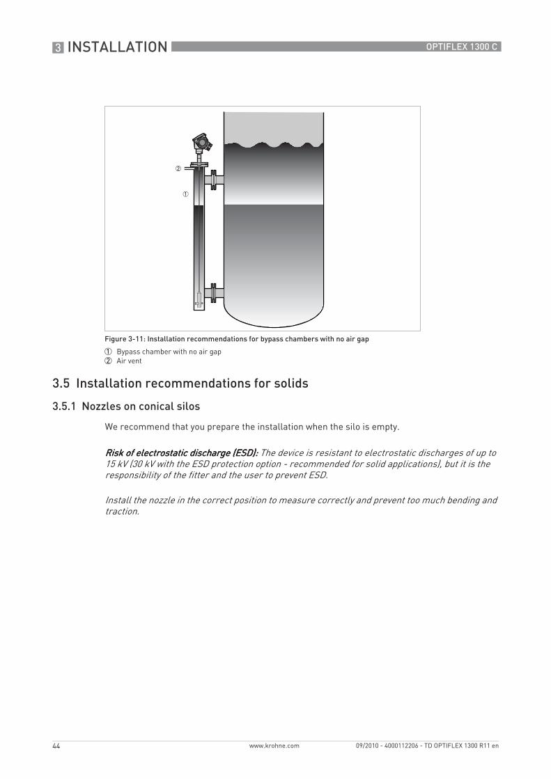
We recommend that you prepare the installation when the silo is empty.
Figure 3-11: Installation recommendations for bypass chambers with no air gap
1 Bypass chamber with no air gap2 Air vent
Risk of electrostatic discharge (ESD): Risk of electrostatic discharge (ESD): Risk of electrostatic discharge (ESD): Risk of electrostatic discharge (ESD): The device is resistant to electrostatic discharges of up to 15 kV (30 kV with the ESD protection option - recommended for solid applications), but it is the responsibility of the fitter and the user to prevent ESD.
Install the nozzle in the correct position to measure correctly and prevent too much bending and traction.

INSTALLATION 3
45
OPTIFLEX 1300 C
www.krohne.com09/2010 - 4000112206 - TD OPTIFLEX 1300 R11 en
Clearance between the probe and other objects in the tank
Figure 3-12: Installation recommendations for solids
1 We recommend installation without a nozzle. If not, h ≤50 mm / 2¨.2 Radius of the tank, r3 The end of the probe must be more than 300 mm / 12¨ above the tank bottom.4 Empty space (radius, Rmin) around the probe.5 The electromagnetic (EM) field generated by the device. It is also the measurement zone of the probe. Make sure that
the EM field is clear of objects and product flow.6 Ground the tank, the product and the probe (if attached).7 If possible, put the process fitting ≥300 mm / 12¨ from the tank wall
Probe type Empty space (radius, Rmin) around the probe
[mm] [inches]
Single cable Ø4 mm / 0.15¨ 4 300 12
Single cable Ø8 mm / 0.3¨ 4 300 12
If the probe is longer than 10 m / 33 ft, we recommend that you do not attach the end of the probe.

3 INSTALLATION
46
OPTIFLEX 1300 C
www.krohne.com 09/2010 - 4000112206 - TD OPTIFLEX 1300 R11 en
3.5.2 Traction loads on the probe
Traction load depends on:• The height and shape of the tank.• The particle size and density.• The rate at which the tank is emptied.
Estimated traction load on the probe in kg
Estimated traction load on the probe in lb
Risk of damage to the cable probe. High loads can break the cable.If the load on the Ø8 mm / 0.3¨ single cable probe is more than 3500 kg / 7700 lb, contact your supplier.
Make sure that the tank roof is resistant to deformation at high loads.
Material Probe length, 10 m Probe length, 20 m Probe length, 30 m
[kg]
Cement 1000 2000 3000
Fly ash 500 1000 1500
Wheat 300 500 1200
Material Probe length, 33 ft Probe length, 65 ft Probe length, 98 ft
[lb]
Cement 2200 4410 6520
Fly ash 1100 2200 3300
Wheat 660 1100 2650
INSTALLATION 3
47
OPTIFLEX 1300 C
www.krohne.com09/2010 - 4000112206 - TD OPTIFLEX 1300 R11 en
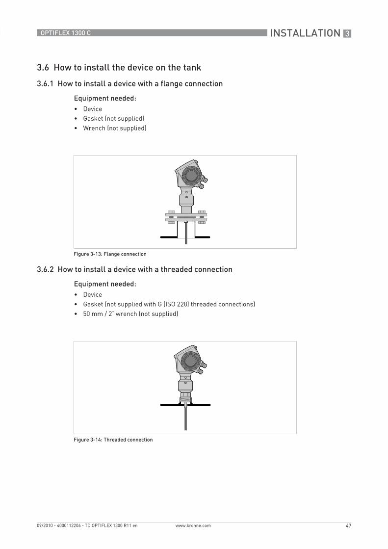
3.6 How to install the device on the tank
3.6.1 How to install a device with a flange connection
Equipment needed:• Device• Gasket (not supplied)• Wrench (not supplied)
3.6.2 How to install a device with a threaded connection
Equipment needed:• Device• Gasket (not supplied with G (ISO 228) threaded connections)• 50 mm / 2¨ wrench (not supplied)
Figure 3-13: Flange connection
Figure 3-14: Threaded connection

3 INSTALLATION
48
OPTIFLEX 1300 C
www.krohne.com 09/2010 - 4000112206 - TD OPTIFLEX 1300 R11 en
3.6.3 Installation recommendations for non-metallic tanks and pits
If you have a device with a single rod or a single cable probe and a thread connection, obey these instructions:• Put a metal sheet between the device and the process connection.i It must have a diameter greater than 200 mm / 8¨.
• Make sure that the metal sheet is in contact with the thread stop on the device.
We recommend that you use DN≥200 / ≥8¨ for flange connections.
If you have a device with a double rod, double cable or coaxial probe, you can ignore these instructions.
Figure 3-15: Installation in a non-metallic tank or pit with a thread connection
1 Non-metallic (plastic...) tank or pit2 Metal sheet, Ø ≥200 mm / 8¨
When the device is installed, make sure that the tank roof has no deformation.
INSTALLATION 3
49
OPTIFLEX 1300 C
www.krohne.com09/2010 - 4000112206 - TD OPTIFLEX 1300 R11 en
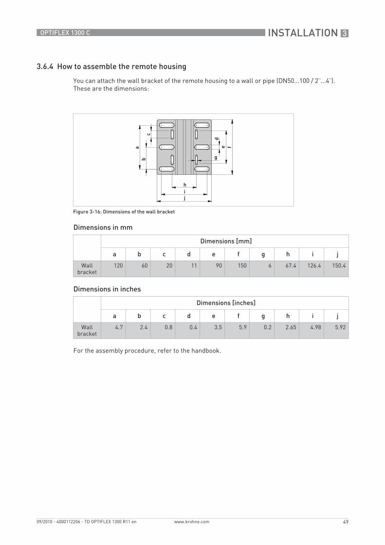
3.6.4 How to assemble the remote housing
You can attach the wall bracket of the remote housing to a wall or pipe (DN50...100 / 2¨...4¨). These are the dimensions:
Dimensions in mm
Dimensions in inches
For the assembly procedure, refer to the handbook.
Figure 3-16: Dimensions of the wall bracket
Dimensions [mm]
a b c d e f g h i j
Wall bracket
120 60 20 11 90 150 6 67.4 126.4 150.4
Dimensions [inches]
a b c d e f g h i j
Wall bracket
4.7 2.4 0.8 0.4 3.5 5.9 0.2 2.65 4.98 5.92

4 ELECTRICAL CONNECTIONS
50
OPTIFLEX 1300 C
www.krohne.com 09/2010 - 4000112206 - TD OPTIFLEX 1300 R11 en
4.1 Safety instructions
4.2 Electrical installation: outputs 1 and 2
Output 1 energizes the device and is used for HART® communication. If the device has the second current output option, use a separate power supply to energize output 2.
All work on the electrical connections may only be carried out with the power disconnected. Take note of the voltage data on the nameplate!
Observe the national regulations for electrical installations!
For devices used in hazardous areas, additional safety notes apply; please refer to the Ex documentation.
Observe without fail the local occupational health and safety regulations. Any work done on the electrical components of the measuring device may only be carried out by properly trained specialists.
Look at the device nameplate to ensure that the device is delivered according to your order. Check for the correct supply voltage printed on the nameplate.
Figure 4-1: Electrical installation
1 Terminal compartment cover2 Output 1: current output -3 Output 1: current output +4 Grounding terminal in the housing5 Output 2: current output -6 Output 2: current output +7 Grounding terminal between the process connection and the converter
If the polarity is not correct, this will not cause damage to the device. But the device will not operate and the output will be 0 mA.

ELECTRICAL CONNECTIONS 4
51
OPTIFLEX 1300 C
www.krohne.com09/2010 - 4000112206 - TD OPTIFLEX 1300 R11 en
4.2.1 Non-Ex
4.2.2 Ex i
4.2.3 Ex d
4.2.4 PROFIBUS PA
For electrical data for PROFIBUS PA networks, refer to the PROFIBUS PA supplement. You can find this documentation on the CD-ROM delivered with the device or it can be downloaded free of charge from the website (Downloadcenter).
4.2.5 FOUNDATION Fieldbus
For electrical data for FOUNDATION Fieldbus networks, refer to the FOUNDATION Fieldbus supplement. You can find this documentation on the CD-ROM delivered with the device or it can be downloaded free of charge from the website (Downloadcenter).
Figure 4-2: Electrical connections for non-Ex devices
1 Power supply
2 Resistor for HART® communication3 Output 1: 14...30 VDC for an output of 22 mA at the terminal4 Output 2: 10...30 VDC for an output of 22 mA at the terminal
For electrical data for Ex i applications, refer to the Ex supplements. You can find this documentation on the CD-ROM delivered with the device or it can be downloaded free of charge from the website (Downloadcenter).
For electrical data for Ex d applications, refer to the Ex supplements. You can find this documentation on the CD-ROM delivered with the device or it can be downloaded free of charge from the website (Downloadcenter).

4 ELECTRICAL CONNECTIONS
52
OPTIFLEX 1300 C
www.krohne.com 09/2010 - 4000112206 - TD OPTIFLEX 1300 R11 en
4.3 Protection category
• Make sure that the gaskets are not damaged.• Make sure that the electrical cables are not damaged.• Make sure that the electrical cables agree with the national electrical code.• The cables are in a loop in front of the device 1 so water does not go into the housing.• Tighten the cable feedthroughs 2.• Close unused cable feedthroughs with dummy plugs 3.
The device fulfills all requirements per protection class IP 66/67 (equivalent to NEMA type 4X (housing) and type 6P (probe)).
Make sure that the cable gland is watertight.
Figure 4-3: How to make the installation agree with protection category IP 67

ELECTRICAL CONNECTIONS 4
53
OPTIFLEX 1300 C
www.krohne.com09/2010 - 4000112206 - TD OPTIFLEX 1300 R11 en
4.4 Networks
4.4.1 General information
The device uses the HART® communication protocol. This protocol agrees with the HART® Communication Foundation standard. The device can be connected point-to-point. It can also operate in a multi-drop network of up to 15 devices.
The device output is factory-set to communicate point-to-point. To change the communication mode from point-to-pointpoint-to-pointpoint-to-pointpoint-to-point to multi-dropmulti-dropmulti-dropmulti-drop, refer to "Network configuration" in the handbook.
4.4.2 Point-to-point networks
Figure 4-4: Point-to-point connection (non-Ex)
1 Address of the device (0 for a point-to-point connection)
2 4...20 mA + HART®
3 Resistor for HART® communication4 Power supply
5 HART® modem
6 HART® communication device

4 ELECTRICAL CONNECTIONS
54
OPTIFLEX 1300 C
www.krohne.com 09/2010 - 4000112206 - TD OPTIFLEX 1300 R11 en
4.4.3 Multi-drop networks
Figure 4-5: Multi-drop network (non-Ex)
1 Address of the device (n+1 for multidrop networks)2 Address of the device (1 for multidrop networks)
3 4 mA + HART®
4 Resistor for HART® communication5 Power supply
6 HART® modem
7 HART® communication device

ELECTRICAL CONNECTIONS 4
55
OPTIFLEX 1300 C
www.krohne.com09/2010 - 4000112206 - TD OPTIFLEX 1300 R11 en
4.4.4 Fieldbus networks
FOUNDATION Fieldbus™ network (non-Ex)
Figure 4-6: FOUNDATION Fieldbus™ network (non-Ex)
1 Field device2 Junction box3 H1 network4 H1/HSE converter5 High Speed Ethernet (HSE)6 Workstation
It is necessary to have a separate power supply to energize devices with the FOUNDATION™ Fieldbus output option (4-wire device with local HART® connection). The FF FF FF FF terminal is connected to a Fieldbus Power Hub. The 24 VDC 24 VDC 24 VDC 24 VDC terminal energizes the device. The power supply is not shown in the illustration.

4 ELECTRICAL CONNECTIONS
56
OPTIFLEX 1300 C
www.krohne.com 09/2010 - 4000112206 - TD OPTIFLEX 1300 R11 en
PROFIBUS PA/DP network (non-Ex)
Figure 4-7: PROFIBUS PA/DP network (non-Ex)
1 Field device2 Bus termination3 PROFIBUS PA bus segment4 Segment coupler (PA/DP link)5 PROFIBUS DP bus line6 Control system (PLC / Class 1 master device)7 Engineering or operator workstation (Control tool / Class 2 master device)
It is necessary to have a separate power supply to energize devices with the PROFIBUS PA output option (4-wire device with local HART® connection). The PROFIBUS PA PROFIBUS PA PROFIBUS PA PROFIBUS PA terminal is connected to a segment coupler. The 24 VDC 24 VDC 24 VDC 24 VDC terminal energizes the device. The power supply is not shown in the illustration.

ORDER FORM 5
57
OPTIFLEX 1300 C
www.krohne.com09/2010 - 4000112206 - TD OPTIFLEX 1300 R11 en
You can help us to assist you as quickly as possible by giving us a few items of information.
Then just fax them to us. Your personal consultant will contact you within 24 hours.
5.1 Device data
Connection type Flange Threaded 1 Specify size:
Connection material 316 L Hastelloy® C-22
Probe end type (cable probes only)
Counterweight Turnbuckle Chuck
Threaded end Crimped end Open end/None
Feedthrough/Sealing 2 Standard / FKM/FPM(-40...+200°C)
Standard / Kalrez® 6375(-20...+200°C)
Standard / EPDM(-50...+150°C)
Housing version 3 Compact, standard (Tmax = +200°C, Pmax = 100 bar)
Compact, high-pressure (Tmax = +200°C, Pmax = 300 bar)
Compact, high-temperature (Tmax = +300°C, Pmax = 100 bar)
Compact, high-temperature / high-pressure (Tmax = +300°C, Pmax = 300 bar)
Remote housing Specify length of conduit for the remote housing (2 m, 4.5 m, 9.5 m or 14.5 m):
Outputs 1 output 4...20 mA/HART®
1 output 4...20 mA/HART® - for interface measurement
2 outputs 4...20 mA/HART® + 4...20 mA
2 outputs 4...20 mA/HART® + 4...20 mA - for interface measurement
PROFIBUS PA (4-wire + local HART®)
FOUNDATION Fieldbus (4-wire + local HART®)
Display Without With Specify language:
Approvals No Ex ATEX Ex ia ATEX Ex d[ia]
WHG 4 FM IS Class 1 Div. 1 (Dual Seal)
FM XP-IS Class 1 Div. 1 (Dual Seal)
CSA IS Class 1 Div. 1 (Dual Seal)
CSA XP-IS Class 1 Div. 2 (Dual Seal)
IECEx Ex ia
IECEx Ex d[ia] 4 NEPSI Ex ia NEPSI Ex dia
ATEX Ex nA INMETRO BR-Ex ia
INMETRO BR-Ex d[ia]
1 This is necessary for a process connection temperature >200°C / 390°F2 The temperature limits for the feedthrough and gasket materials must agree with the temperature limits of the hous-
ing version.3 Refer also to the Pressure / temperature table for probe selection in the "Technical data" section.4 Pending
5 ORDER FORM
58
OPTIFLEX 1300 C
www.krohne.com 09/2010 - 4000112206 - TD OPTIFLEX 1300 R11 en
5.2 Rating data
5.3 Contact data
Product name:
Operating pressure:
Rated pressure:
Process connection temperature:
Ambient temperature:
Viscosity:
Measurand (level, volume,...):
Tank height:
Comments (indoors, exposed to weather, ...):
Company:
Contact person:
Telephone number:
Fax number:
E-mail:

NOTES 6
59
OPTIFLEX 1300 C
www.krohne.com09/2010 - 4000112206 - TD OPTIFLEX 1300 R11 en

KROHNE product overview
• Electromagnetic flowmeters
• Variable area flowmeters
• Ultrasonic flowmeters
• Mass flowmeters
• Vortex flowmeters
• Flow controllers
• Level meters
• Temperature meters
• Pressure meters
• Analysis products
• Measuring systems for the oil and gas industry
• Measuring systems for sea-going tankers
Head Office KROHNE Messtechnik GmbHLudwig-Krohne-Str. 5D-47058 Duisburg (Germany)Tel.:+49 (0)203 301 0Fax:+49 (0)203 301 10389 [email protected]
© K
RO
HN
E 09
/201
0 -
4000
1122
06 -
TD
OP
TIFL
EX 1
300
R11
en
- Su
bjec
t to
chan
ge w
ithou
t not
ice.
The current list of all KROHNE contacts and addresses can be found at:www.krohne.com
KK
K


![LUPA 1300 2 Datasheet[1]](https://img.pdfslide.us/doc/110x75/577ce7321a28abf1039490e2/lupa-1300-2-datasheet1.jpg)