Embed Size (px)
Citation preview

Air distribution systems
Opticlean OC-Q....
DS 4136 E 06.2013/1

2
ww
w.k
rant
z.de
D
S 41
36
p. 2
0
6.20
13
ww
w.k
rant
z.de
D
S 41
36
p. 3
0
6.20
13
OpticleanPreliminary remarks, mode of operation and construction design
Preliminary remarks
KRANTZ KOMPONENTEN has developed the Opticlean OC-Q in
order to combine in a single product the main features of a ceiling-
mounted supply air outlet for diffuse indoor air flow, i.e.
– high level of thermal comfort
– unobtrusive integration into the suspended ceiling
– low amount of dirt accumulated on the ceiling
– low sound power level and low pressure drop.
The Opticlean from KRANTZ KOMPONENTEN is suitable for use
in suspended ceiling systems.
In grid ceilings with modules of 625 x 625 mm or 600 x 600 mm,
the standard design can be laid from above onto the T-bars of
the ceiling system, instead of ceiling tiles, and connected to the
supply air ductwork.
Another square standard design 1) is available for integration into
gypsum board ceilings.
Further, there are special solutions for a number of other quite
common ceiling systems, e.g. metal tile ceilings with clip-in or lay-
in tiles; these solutions are tailored to the specific ceiling systems.
As standard the outlet faceplate has round perforations with
diagonal pitch; the hole diameter is 2.8 mm, the pitch 5.5 mm.
This perforation pattern corresponds to the typical appearance of
usual metal tiles for ceiling systems. Thus, the integration of this
air outlet into the ceiling is unobtrusive. If the perforation pattern of
the ceiling tiles is the same, it is hardly possible to distinguish the
Opticlean within the ceiling. The Opticlean can be used with other
perforation patterns, but this requires technical clarification with
our product specialists.
Application
– For ceiling heights 2.5 to 4.5 m
– Maximum temperature difference between supply and indoor
air: ±10 K 2)
– Volume flow rate range from 11 to 239 l/s [40 to 860 m3/h]
– Also usable as return air inlet
Mode of operation
The supply air flows very evenly through the perforated faceplate
and spreads radially and horizontally. As the supply air induces in-
door air, the flow velocity and the temperature difference between
supply and indoor air decrease rapidly; this results in a comfort-
able thermal environment with low indoor air velocities and even
indoor air temperatures in the occupied zone.
The induced indoor air does not come into contact with the per-
forated faceplate because a layer acting as an air cushion forms
under the air outlet. This is why far less dirt accumulates on the
ceiling than is the case with turbulent-flow outlets.
If the Opticlean is installed near a wall or in a room corner, it is
possible to alter the discharge direction by using segment covers
in order to avoid air draughts in the occupied zone.
2
1
Figure 1: Air flow pattern of the Opticlean
Figure 2: Air flow pattern made visible by smoke tracer
Construction design
The Opticlean is available in 7 sizes.
It consists of the square air distribution element 1 which is fixed
to the perforated faceplate 2. The underside of the air distribution
element has a black coating. The outlet is connected to the sup-
ply air ductwork either directly by a flexible duct (connection type
O) or via a connection box 3 (connection type K) which can be
optionally fitted with a volume flow damper 5 adjustable at the
connection spigot 4. For 2-way or 3-way discharge, the upper
side of the perforated faceplate will be fitted with segment
covers 6 made of acoustic fleece.
4-way discharge 3-way discharge 2-way symmetric discharge
2-way asym-metric discharge
6 6 6
Figure 3: Alteration of discharge direction by use of segment
covers
1) For Opticlean with circular faceplate, see brochure ref. DS 41742) When heating, +10 K up to 3 m ceiling height, +5 K up to 4.5 m ceiling
height
3
ww
w.k
rant
z.de
D
S 41
36
p. 2
0
6.20
13
ww
w.k
rant
z.de
D
S 41
36
p. 3
0
6.20
13OpticleanConstruction design and dimensions
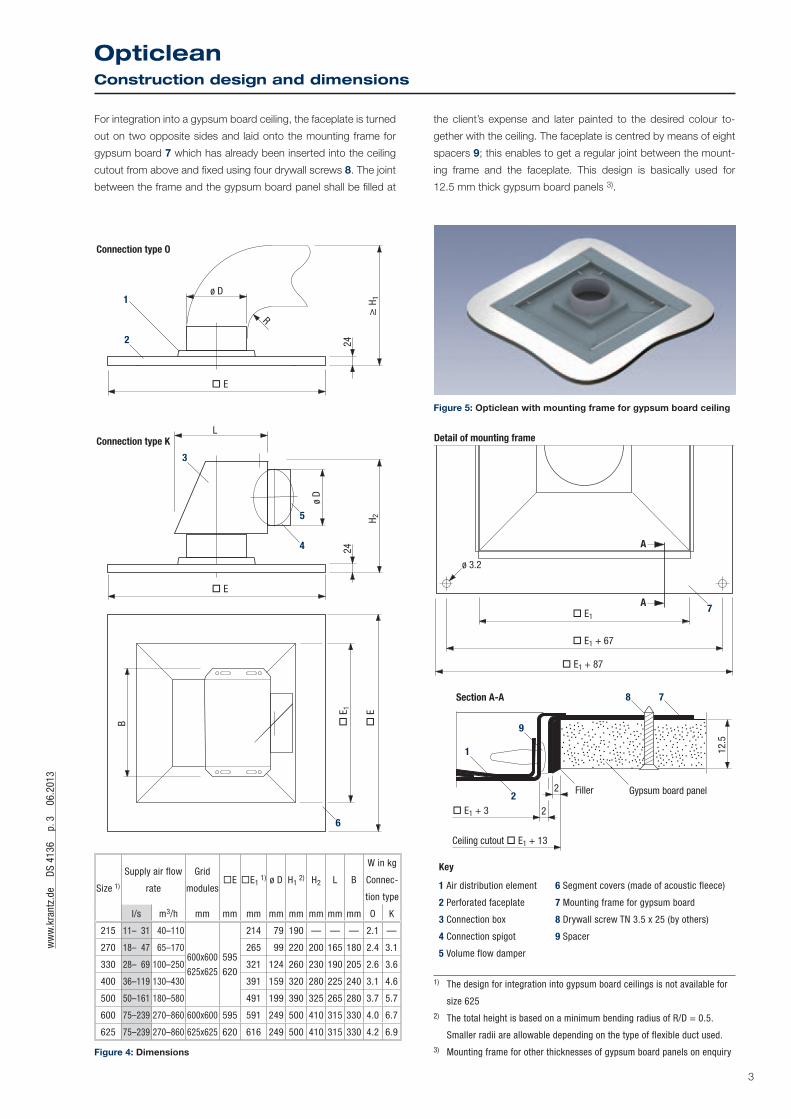
For integration into a gypsum board ceiling, the faceplate is turned
out on two opposite sides and laid onto the mounting frame for
gypsum board 7 which has already been inserted into the ceiling
cutout from above and fixed using four drywall screws 8. The joint
between the frame and the gypsum board panel shall be filled at
24
H
1
EH 2
24
ø D
L
E
E
1
B
ø D
R
1
2
3
4
5
E
6
Connection type O
Connection type K
Size 1)
Supply air flow
rate
Grid
modulesE E1
1) ø D H1 2) H2 L B
W in kg
Connec-
tion type
l/s m3/h mm mm mm mm mm mm mm mm O K
215 11– 31 40–110
600x600
625x625
595
620
214 79 190 — — — 2.1 —
270 18– 47 65–170 265 99 220 200 165 180 2.4 3.1
330 28– 69 100–250 321 124 260 230 190 205 2.6 3.6
400 36–119 130–430 391 159 320 280 225 240 3.1 4.6
500 50–161 180–580 491 199 390 325 265 280 3.7 5.7
600 75–239 270–860 600x600 595 591 249 500 410 315 330 4.0 6.7
625 75–239 270–860 625x625 620 616 249 500 410 315 330 4.2 6.9
Figure 4: Dimensions
Figure 5: Opticlean with mounting frame for gypsum board ceiling
E1
E1 + 67
A
A
2
2
9
1
2
7
7
8
E1 + 87
E1 + 3
Detail of mounting frame
Section A-A
Ceiling cutout E1 + 13
Filler Gypsum board panel
ø 3.2
12.5
Key
1 Air distribution element
2 Perforated faceplate
3 Connection box
4 Connection spigot
5 Volume flow damper
6 Segment covers (made of acoustic fleece)
7 Mounting frame for gypsum board
8 Drywall screw TN 3.5 x 25 (by others)
9 Spacer
1) The design for integration into gypsum board ceilings is not available for
size 625 2) The total height is based on a minimum bending radius of R/D = 0.5.
Smaller radii are allowable depending on the type of flexible duct used. 3) Mounting frame for other thicknesses of gypsum board panels on enquiry
the client’s expense and later painted to the desired colour to-
gether with the ceiling. The faceplate is centred by means of eight
spacers 9; this enables to get a regular joint between the mount-
ing frame and the faceplate. This design is basically used for
12.5 mm thick gypsum board panels 3).

4
ww
w.k
rant
z.de
D
S 41
36
p. 4
0
6.20
13
ww
w.k
rant
z.de
D
S 41
36
p. 5
0
6.20
13
OpticleanDesign specifications
Figure 6: Opticlean installed in a grid ceiling
Figure 7: Opticlean installed in a gypsum board ceiling
Figure 8: Opticlean for connection to a flexible duct or 90° elbow
Figure 9: Opticlean with connection box
Design specifications
Return air inlets
The Opticlean is mainly designed for supply air distribution. It is
also possible to use it for return air extraction, but then it is not
protected from dirtying (no ‘clean’ function). This is in particular
true when installed in rooms with higher particle load (e.g. corri-
dors, smoking area, etc.).
Connection types
The outlet connection to the ductwork is possible via
• a flexible duct or a 90° elbow (Figure 8) or
• a connection box (Figure 9).
The connection box option is recommended in particular when a
volume flow damper is required. As a rule, this connection type
is louder by about 3 – 5 dB(A) ref. 10-12W than the flexible duct
connection at the same air flow rate.
With connection box the space requirement in height is less than
with direct flexible duct connection. The values are given in the
table of dimensions.
For installation in false ceilings with very low plenums, the solution
is to use a very flat connection box 1).
As standard, the Opticlean diffusers are designed for use with
metal ceiling tiles having a thickness of 0.6 mm 2) and fitted
with round perforations 2.8 mm in diameter with diagonal pitch
of 5.5 mm. Their mode of operation has been optimized for use
with such ceiling tiles. Basically, they can also be used with other
ceiling tiles, but then the air flow and acoustic data are likely to
differ. It is recommended not to use the Opticlean with ceiling tiles
thicker than 0.6 mm and perforations smaller than 2 mm. For such
configurations a technical check should be made by our product
specialists.
1) More information on enquiry2) Without powder coating or paint

5
ww
w.k
rant
z.de
D
S 41
36
p. 4
0
6.20
13
ww
w.k
rant
z.de
D
S 41
36
p. 5
0
6.20
13OpticleanDesign specifications
There are adequate solutions for most common metal ceiling tiles.
Further, special sizes (170, 300 and 350) are available. Technical
data can be provided on request.
Minimum air outlet centre spacing
When designing the ventilation system, the minimum air outlet
centre spacing given in Graph 2 is to be taken into consideration.
The spacing shall be halved for outlet placement near a wall.
If the space configuration does not make it possible to comply
with the minimum centre spacing, the Opticlean outlets can be
fitted with segment covers which will enable to reduce the air flow
rate by 25% or 50%.
a) The segment cover in Fig. 10 is for 3-way discharge
Wal
l
Figure 10: 3-way discharge in front of a wall
b) If the specified minimum centre spacing between two outlets
cannot be complied with, we recommend an arrangement as
shown in Figure 11.
a 0.5 · tmin
value under minimum centre spacing
Figure 11: Position of segment cover when the outlet spacing is
under the minimum value
c) In narrow spaces (e.g. corridors) we recommend a segment
cover as shown in Figure 12.
Wal
l
Wal
l
Figure 12: Segment cover for narrow spaces, for instance
d) If the Opticlean is placed in a room corner, the segment cover
should be as shown in Figure 13.
Wal
l
Wall
Figure 13: Segment cover for asymmetric discharge, e.g. for outlet
placement in a room corner

6
ww
w.k
rant
z.de
D
S 41
36
p. 6
0
6.20
13
ww
w.k
rant
z.de
D
S 41
36
p. 7
0
6.20
13/1
OpticleanComfort criteria
Comfort criteria 1)
The outlet layout must comply with the maximum allowable in-
door air velocities u in the occupied zone in the cooling mode.
The indoor air velocity depends on the cooling load that is to be
removed from the room. The maximum specific cooling capacity
q· depends on the discharge height and the maximum allowable
indoor air velocity u (Graph 1).
Graph 1 enables to determine for the cooling mode the maximum
specific volume flow rate V· Sp max in relation to the maximum
specific cooling capacity and the maximum temperature differ-
ence DJmax. The volume flow rate supplied to the room V· Sp tats
may not exceed this value.
Graph 2 enables to determine the minimum centre spacing
between two outlets on the basis of the maximum specific volume
flow rate.
300
200
100
0
104
0.3 0.350.2
Maximum allowable indoor air velocity u in m/s
Max
imum
spe
cific
vol
ume
flow
rate
V· Sp m
ax in
l/(s
·m2 )
Disc
harg
e he
ight
H in
m
2.7
0.1
Max
imum
spe
cific
coo
ling
capa
city
q· in W
/m2
0
20
15
10
5
25
0
30
25
15
20
10
5
Temperature difference max –8 K –10 K
Graph 1: Maximum specific volume flow rate
7
8
9
10
12
1416
18
Max. specific volume flow rate V· Sp max in l/(s·m2)
Min
imum
air
outle
t cen
tre s
paci
ng t m
in in
m
1
2
3
4
6
5
Air outlet volume flow rate V·A in l/s20 50 100 150 200 220
Graph 2: Minimum air outlet centre spacing
Key for layout:
V· A = volume flow rate per air outlet in l/s
V· A max = max. volume flow rate per air outlet when cooling in l/s
V· A min = min. volume flow rate per air outlet when cooling in l/s
V· Sp max = max. specific volume flow rate per m2 in l/(s·m2)
V· Sp tats = actual specific volume flow rate per m2 of floor area in l/(s·m2)
u = max. allowable indoor air velocity in m/s
q· = max. specific cooling capacity in W/m2
DJmax = max. temperature difference supply air to return air in K
tmin = minimum air outlet centre spacing in m
H = discharge height in m
LWA = sound power level in dB(A) ref. 10-12 W
Dpt = total pressure drop in Pa
Layout example
Size 500
Application Office building
1 Supply air volume flow rate V· l/s 666
2 Discharge height H m 2.7
3 Floor area A m2 120
4 Maximum allowable
sound power level LWA dB(A) ref. 10-12W
38
5 Temperature difference DJmax K –10
6 Comfort criteria
– Maximum indoor air
velocity u m/s
– Maximum specific
volume flow rate V· Sp max l/(s·m2)
– Actual specific
volume flow rate V· Sp tats l/(s·m2)
Criterion is met if V· Sp tats < V· Sp max
0,2
10
[from 1 : 3]
6
From nomogram
7 V· A max l/s 111
8 Z [³ V· : V· A max] units 6
9 V· A [V· : Z] l/s 111
10 LWA dB(A) ref. 10-12W 36
11 Dpt Pa 40
12 tmin [Graph 2] m 3.3
1) See our brochure ref. TB 69 ‘Layout specifications for thermal comfort’

7
ww
w.k
rant
z.de
D
S 41
36
p. 6
0
6.20
13
ww
w.k
rant
z.de
D
S 41
36
p. 7
0
6.20
13/1
OpticleanLayout sheet
Opticlean – Supply air outlet
22020050403012 l/s10020
50 100 200 300 400 500 80040
40 100 200 300 400 500 90050
40
50
20
30
10
40
50
20
30
10
70
4050
20
30
5
10
4
80
4050
20
30
6
10
Air outlet volume flow rate V·A
Air outlet volume flow rate V·A
Size 2
15
Size
270
Size
330
Size
400
Size
500
Size
600
Size
625
Size
215
Size 2
70
Size 3
30
Size 4
00Siz
e 500
Size 6
00 an
d 625
Flexible duct connection 1)
Soun
d po
wer
leve
l LW
A in
dB(
A) re
f. 10
-12
W
Connection box
Soun
d po
wer
leve
l LW
A in
dB(
A) re
f. 10
-12
W
Size
215
Size
270
Size
330
Size
400
Size
500
Size
600
and
625
Size
215
Size
270
Size
330
Size
400
Size
500
Size
600
and
625
Tota
l pre
ssur
e dr
op
p t in
Pa
Tota
l pre
ssur
e dr
op
p t in
Pa
22020050403012 l/s10020
m3/h
l/s
m3/h
25020050403012 10020
25020050403012 10020
Notes:
Sound power levels related to octave band centre frequencies are
available on request.
The above-mentioned values for sound power level and pressure
drop apply to the standard design. The faceplate design has an
effect on the outlet operation and its technical features. Where
necessary, the suitability of other faceplate designs is to be con-
firmed by tests.
Opticlean used as return air inlet
60 100 200 300 400 500 900
2502001005040302017
2502001005040302017
60 100 200 300 400 500 900
2502001005040302017
2502001005040302017
40
50
20
30
10
40
50
20
30
10
100
4050
20
30
5
10
4
80
4050
20
30
10
100
120
Size 2
15
Size 2
70
Size 3
30
Size 4
00
Size 5
00
Size 6
00
Size 6
25
Size 2
15Siz
e 270
Size 3
30
Size 4
00Siz
e 500
Flexible duct connection
Tota
l pre
ssur
e dr
op
p t in
Pa
Soun
d po
wer
leve
l LW
A in
dB(
A) re
f. 10
-12
W
Air inlet volume flow rate V·A
Connection box
Tota
l pre
ssur
e dr
op
p t in
Pa
Soun
d po
wer
leve
l LW
A in
dB(
A) re
f. 10
-12
W
Size 2
15
Size 2
70
Size 3
30
Size 4
00 Size 5
00
Size 2
15Siz
e 270
Size 3
30
Size 4
00Siz
e 500
Size 6
00 an
d 625
m3/h
Air inlet volume flow rate V·A
m3/h
l/s
l/s
Size 6
00 an
d 625
Size 6
00 an
d 625
1) With a straight duct, the sound power level is lower by
2 – 4 dB(A) ref. 10-12W
8
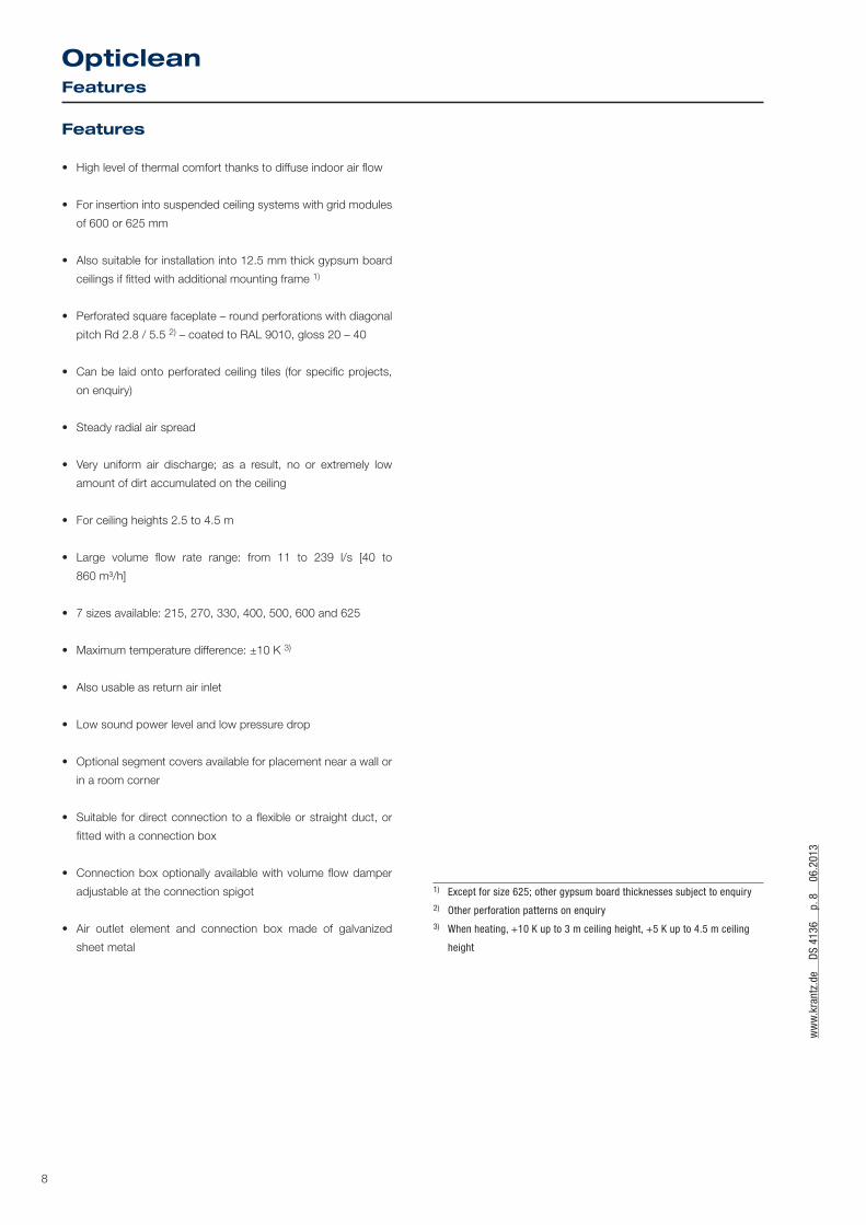
Features
• High level of thermal comfort thanks to diffuse indoor air flow
• For insertion into suspended ceiling systems with grid modules
of 600 or 625 mm
• Also suitable for installation into 12.5 mm thick gypsum board
ceilings if fitted with additional mounting frame 1)
• Perforated square faceplate – round perforations with diagonal
pitch Rd 2.8 / 5.5 2) – coated to RAL 9010, gloss 20 – 40
• Can be laid onto perforated ceiling tiles (for specific projects,
on enquiry)
• Steady radial air spread
• Very uniform air discharge; as a result, no or extremely low
amount of dirt accumulated on the ceiling
• For ceiling heights 2.5 to 4.5 m
• Large volume flow rate range: from 11 to 239 l/s [40 to
860 m³/h]
• 7 sizes available: 215, 270, 330, 400, 500, 600 and 625
• Maximum temperature difference: ±10 K 3)
• Also usable as return air inlet
• Low sound power level and low pressure drop
• Optional segment covers available for placement near a wall or
in a room corner
• Suitable for direct connection to a flexible or straight duct, or
fitted with a connection box
• Connection box optionally available with volume flow damper
adjustable at the connection spigot
• Air outlet element and connection box made of galvanized
sheet metal
1) Except for size 625; other gypsum board thicknesses subject to enquiry2) Other perforation patterns on enquiry3) When heating, +10 K up to 3 m ceiling height, +5 K up to 4.5 m ceiling
height
ww
w.k
rant
z.de
D
S 41
36
p. 8
0
6.20
13
ww
w.k
rant
z.de
D
S 41
36
p. 9
0
6.20
13
OpticleanFeatures

9
ww
w.k
rant
z.de
D
S 41
36
p. 8
0
6.20
13
ww
w.k
rant
z.de
D
S 41
36
p. 9
0
6.20
13OpticleanType code and tender text
Type code
OC – __ / ___ / _ – _ _ – ___
Opt
icle
an –
––––
–– Ge
omet
ry –
––––
–– Si
ze –
––––
––––
–– Se
gmen
t cov
er –
–– Co
nnec
tion
type
––
Dam
per
–––
––––
– Su
rfac
e fin
ish
–––
–
Geometry
Q1 = square faceplate for square tile ceiling 600 mm x 600 mm
Q2 = square faceplate for square tile ceiling 625 mm x 625 mm
QG = square faceplate with mounting frame for 12.5 mm thick
gypsum board ceiling (except for size 625) 1)
Size
215 = size 215 500 = size 500
270 = size 270 600 = size 600
330 = size 330 625 = size 625
400 = size 400
Segment cover 2)
0 = none (4-way discharge)
1 = 3-way discharge
2 = 2-way symmetric discharge
3 = 2-way asymmetric discharge
Connection type
O = no connection piece (only outlet element) 3)
K = connection box
Damper
O = no volume flow damper
S = with volume flow damper adjustable at spigot
Surface finish
9010 = face painted to RAL 9010, semi-matt
…. = face painted to RAL ….
Tender text
……… units
Opticlean – Supply air outlet with horizontal discharge for in-
sertion into suspended ceiling systems with grid modules of
625 x 625 mm and 600 x 600 mm or for integration into 12.5 mm
thick gypsum board ceilings, designed to generate a high-quality
indoor air flow at low velocities and uniform indoor air tempera-
tures;
unobtrusive integration into the ceiling;
extremely low amount of dirt accumulated on the ceiling thanks to
very uniform air spread and the resultant air cushion.
Outlet consisting of:
– square faceplate fitted with round perforations with diagonal
pitch, hole diameter 2.8 mm, pitch 5.5 mm;
– where applicable, with mounting frame for integration into a
12.5 mm thick gypsum board ceiling 1);
– optional segment covers to enable 3-way or 2-way discharge;
– air distribution element with top connection spigot for connec-
tion to a flexible or straight duct;
– optional connection box with lateral connection spigot as well
as suspension brackets, optionally fitted with volume flow
damper adjustable at the connection spigot.
Material:
– Faceplate made of galvanized sheet metal powder coated to
RAL ….
– Mounting frame made of galvanized sheet metal
– Air distribution element made of galvanized sheet metal
– Connection box made of galvanized sheet metal
Make: KRANTZ KOMPONENTEN
Type: OC – Q_ / __ / _ – _ _ – ___
Subject to technical alterations.
1) On enquiry also available for other gypsum board thicknesses2) If nothing is specified, the outlet will be supplied without segment cover.
The segment covers serve to reduce the volume flow rate. 3) For direct connection using a flexible duct or 90° elbow
_/0
_/3_/1
_/2

Distributore in esclusiva per l’Italia:
F.C.R. Filtrazione Condizionamento Riscaldamento SpAVia E. Fermi, 3 - 20092 Cinisello Balsamo (MI) - Italyphone +39 02 61798 1 - fax +39 02 61798 300www.fcr.it - [email protected]