Embed Size (px)
Citation preview
IEEE Robotics & Automation Magazine96 1070-9932/08/$25.00ª2008 IEEE MARCH 2008
Optic-Flow-BasedCollision Avoidance
Applications Using a Hybrid MAV
BY WILLIAM E. GREEN AND PAUL Y. OH
Recent terrorist attacks on the United States haveexposed the need for better surveillance and situa-tional awareness technologies. Organizations createdto address these needs are aggressively fundingresearch in the use of micro air vehicles (MAVs) for
homeland security missions. Such missions have been occur-ring in caves, tunnels, and urban areas. By mimicking flyinginsects, which navigate in these complex environments regu-larly, an optic flow collision avoidance system for MAVs wasprototyped. However, there were certain instances (e.g., flyingdirectly into a corner) where this system failed. To address this,a new MAV platform was prototyped, which enabled a quicktransition from cruise flight into a hovering mode to avoidsuch a collision. The hybrid MAVoffers the endurance superi-ority of a fixed-wing aircraft along with the hovering capabil-ities of a rotorcraft. This article details the applications anddesign of a hybrid MAV in conjunction with sensing and con-trol techniques to perform autonomous hovering and collisionavoidance. This is, to the best of our knowledge, the first docu-mented success of hovering a fixed-wing MAVautonomously.
The Novel MAV PlatformMore often, homeland security and disaster mitigation effortshave taken place in unforeseen environments, which include
caves, tunnels, forests, cities, and even inside urban structures.Performing various tasks such as surveillance, reconnaissance,bomb damage assessment, or search and rescue within an unfa-miliar territory is dangerous and also requires a large, diverse taskforce. Unmanned robotic vehicles could assist in such missionsby providing situational awareness without risking the lives ofsoldiers, first responders, or other personnel. Although ground-based robots have had many successes in search-and-rescue sit-uations [6], they move slowly, have trouble traversing ruggedterrain, and can still put the operator at risk. Alternatively, smallunmanned aerial vehicles (UAVs) can provide soldiers andemergency-response personnel with an eye-in-the-sky perspec-tive (Figure 1). On an even smaller scale, tiny, bird-sized aircraftsor MAVs can be designed to fit in a backpack and can be rapidlydeployed to provide around-the-corner or over-the-hill surveil-lance. Navigating in urban environments, however, remains achallenging problem for UAVs. In [7], promising results areshown for a rotorcraft equipped with a SICK laser scanner.Because lift decreases with platform size, carrying this type ofsensor on MAVs is not feasible.
To design an MAV that can fly autonomously in and aroundbuildings, inspiration came from looking at nature. Flyinginsects, such as honeybees and fruit flies, use optic flow to navi-gate in complex and dynamic environments [2], [9]. By mim-icking insect behaviors, we were the first to demonstrate taskssuch as collision avoidance and landing inside an urbanDigital Object Identifier 10.1109/MRA.2008.919023
Authorized licensed use limited to: The Ohio State University. Downloaded on December 5, 2008 at 13:34 from IEEE Xplore. Restrictions apply.
structure [4]. More recently, optic flow has been used outdoorsto avoid collisions with a tall building and to navigate throughcanyons [5]. Although using optic flow outdoors in rich tex-ture areas seems promising, there are some limitations whenusing this technique as the only sensing modality inside build-ings (e.g., flying directly at a wall with no texture). To addressthese sensor limitations, we prototyped a fixed-wing MAV thatis capable of a quick transition into the hovering mode to avoidcollisions directly in front of the aircraft. This article illustrateshow integrating optic flow sensing, for lateral collision avoid-ance, with a novel MAV platform results in a vehicle that is wellsuited for flight in urban areas. The article also discusses opticflow and reactive control experiments mimicking flying insectsas well as the fixed-wing MAV with hovering capabilities. Theautonomous control of the aircraft’s attitude during a hover isdetailed later along with near-future goals.
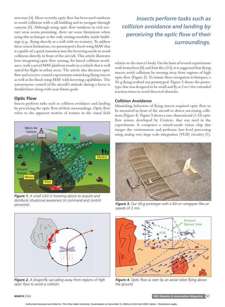
Optic FlowInsects perform tasks such as collision avoidance and landingby perceiving the optic flow of their surroundings. Optic flowrefers to the apparent motion of texture in the visual field
relative to the insect’s body. On the basis of several experimentswith honeybees [8] and fruit flies [10], it is suggested that flyinginsects avoid collisions by turning away from regions of highoptic flow (Figure 2). To mimic these navigation techniques, a30-g flying testbed was prototyped. Figure 3 shows the proto-type that was designed to be small and fly at 2 m/s for extendedreaction times to avoid detected obstacles.
Collision AvoidanceMimicking behaviors of flying insects required optic flow tobe measured in front of the aircraft to detect oncoming colli-sions (Figure 4). Figure 5 shows a one-dimensional (1-D) opticflow sensor, developed by Centeye, that was used in theexperiments. It comprises a mixed-mode vision chip thatimages the environment and performs low-level processingusing analog very large scale integration (VLSI) circuitry [1].
Micro AirVehicle
GroundRobots
Medics
Pilot
Mines
Figure 1. A small UAV is hovering above to acquire anddistribute situational awareness to command and controlpersonnel.
Figure 2. A dragonfly saccading away from regions of highoptic flow to avoid a collision.
Figure 3. Our 30-g prototype with a 60-cm wingspan flies atspeeds of 2 m/s.
ForwardSensor View
FOE
Figure 4. Optic flow as seen by an aerial robot flying abovethe ground.
Insects perform tasks such as
collision avoidance and landing by
perceiving the optic flow of their
surroundings.
IEEE Robotics & Automation MagazineMARCH 2008 97
Authorized licensed use limited to: The Ohio State University. Downloaded on December 5, 2008 at 13:34 from IEEE Xplore. Restrictions apply.
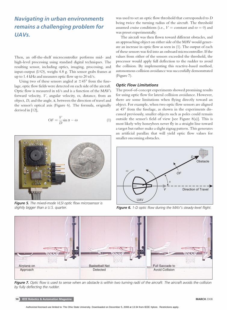
Then, an off-the-shelf microcontroller performs mid- andhigh-level processing using standard digital techniques. Theresulting sensor, including optics, imaging, processing, andinput-output (I/O), weighs 4.8 g. This sensor grabs frames atup to 1.4 kHz and measures optic flow up to 20 rd/s.
Using two of these sensors angled at 645� from the fuse-lage, optic flow fields were detected on each side of the aircraft.Optic flow is measured in rd/s and is a function of the MAV’sforward velocity, V , angular velocity, x, distance, from anobject, D, and the angle, a, between the direction of travel andthe sensor’s optical axis (Figure 6). The formula, originallyderived in [12],
OF ¼ VD
sin a� x (1)
was used to set an optic flow threshold that corresponded to Dbeing twice the turning radius of the aircraft. The thresholdassumed cruise conditions (i.e., V ¼ constant and x ¼ 0) andwas preset experimentally.
The aircraft was then flown toward different obstacles, andan approaching object on either side of the MAV would gener-ate an increase in optic flow as seen in (1). The output of eachof these sensors was fed into an onboard microcontroller. If thevalues from either of the sensors exceeded the threshold, theprocessor would apply full deflection to the rudder to avoidthe collision. By implementing this reactive-based method,autonomous collision avoidance was successfully demonstrated(Figure 7).
Optic Flow LimitationsThe proof-of-concept experiments showed promising resultsfor using optic flow for lateral collision avoidance. However,there are some limitations when flying directly toward anobject. For example, when two optic flow sensors are alignedat 45� from the fuselage, as shown in the experiments dis-cussed previously, smaller objects such as poles could remainoutside the sensor’s field of view [see Figure 8(a)]. This ismost likely why honeybees never fly in a straight line towarda target but rather make a slight zigzag pattern. This generatesan artificial parallax that will yield optic flow values forsmaller oncoming obstacles.
Figure 5. The mixed-mode VLSI optic flow microsensor isslightly bigger than a U.S. quarter.
Direction of Travel
Obstacle
UAV
V
D
OF
�
�
Figure 6. 1-D optic flow during the MAV’s steady-level flight.
Airplane onApproach
Basketball NetDetected
Full Saccade toAvoid Collision
Figure 7. Optic flow is used to sense when an obstacle is within two turning radii of the aircraft. The aircraft avoids the collisionby fully deflecting the rudder.
Navigating in urban environments
remains a challenging problem for
UAVs.
IEEE Robotics & Automation Magazine98 MARCH 2008
Authorized licensed use limited to: The Ohio State University. Downloaded on December 5, 2008 at 13:34 from IEEE Xplore. Restrictions apply.
Similarly, optic-flow-based collision avoidance is also insuf-ficient when flying directly toward larger obstacles such as walls.Figure 8(b) shows an example of this scenario. In [14], thediverging optic flow field generated by the wall was used totrigger a warning 2 m before the collision. However, theexperiment was performed in an artificially textured environ-ment (i.e., alternating white and black sheets were used aswalls). Realistically, walls are often homogeneous and have littletexture. Therefore, this method will most likely fail, especiallysince the wall will be the only object in the sensor’s field ofview. When fruit flies are presented with this scenario in [11],they stick out their legs in preparation for landing. Landing on awall is obviously not feasible for MAVs. However, a quicktransition to a stationary attitude is possible; i.e., a fixed-wingMAV can be designed to quickly transition to a hover to avoidcollisions in these instances.
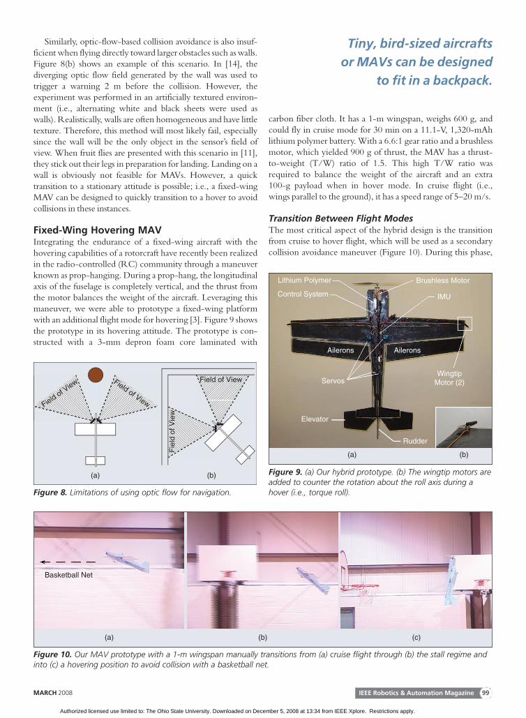
Fixed-Wing Hovering MAVIntegrating the endurance of a fixed-wing aircraft with thehovering capabilities of a rotorcraft have recently been realizedin the radio-controlled (RC) community through a maneuverknown as prop-hanging. During a prop-hang, the longitudinalaxis of the fuselage is completely vertical, and the thrust fromthe motor balances the weight of the aircraft. Leveraging thismaneuver, we were able to prototype a fixed-wing platformwith an additional flight mode for hovering [3]. Figure 9 showsthe prototype in its hovering attitude. The prototype is con-structed with a 3-mm depron foam core laminated with
carbon fiber cloth. It has a 1-m wingspan, weighs 600 g, andcould fly in cruise mode for 30 min on a 11.1-V, 1,320-mAhlithium polymer battery. With a 6.6:1 gear ratio and a brushlessmotor, which yielded 900 g of thrust, the MAV has a thrust-to-weight (T/W) ratio of 1.5. This high T/W ratio wasrequired to balance the weight of the aircraft and an extra100-g payload when in hover mode. In cruise flight (i.e.,wings parallel to the ground), it has a speed range of 5–20 m/s.
Transition Between Flight ModesThe most critical aspect of the hybrid design is the transitionfrom cruise to hover flight, which will be used as a secondarycollision avoidance maneuver (Figure 10). During this phase,
Field of View Field of View
Field of View
Fie
ld o
f Vie
w
(a) (b)
Figure 8. Limitations of using optic flow for navigation.
Lithium Polymer
Control System
Servos
Elevator
Rudder
Ailerons Ailerons
WingtipMotor (2)
IMU
Brushless Motor
(a) (b)
Figure 9. (a) Our hybrid prototype. (b) The wingtip motors areadded to counter the rotation about the roll axis during ahover (i.e., torque roll).
Basketball Net
(a) (b) (c)
Figure 10. Our MAV prototype with a 1-m wingspan manually transitions from (a) cruise flight through (b) the stall regime andinto (c) a hovering position to avoid collision with a basketball net.
Tiny, bird-sized aircrafts
or MAVs can be designed
to fit in a backpack.
IEEE Robotics & Automation MagazineMARCH 2008 99
Authorized licensed use limited to: The Ohio State University. Downloaded on December 5, 2008 at 13:34 from IEEE Xplore. Restrictions apply.
there exists an angle-of-attack, a, for which the wings are nolonger a contributing factor to the lift component (i.e., stall).To achieve the transition, the aircraft has to leverage itsmomentum and essentially overpower its way through the stallregime. This requires a high T/W ratio so that the momentumis not lost through the transition. Furthermore, as the aircraft istransitioning from cruise flight (minimum thrust) to the hover-ing flight mode, the throttle must be increased to balance theweight of the aircraft. The transition back to cruise mode is lesscomplex. Vertical acceleration is required first to give the plane
some momentum, and then the elevator is deflected to pitchthe aircraft forward into cruise mode.
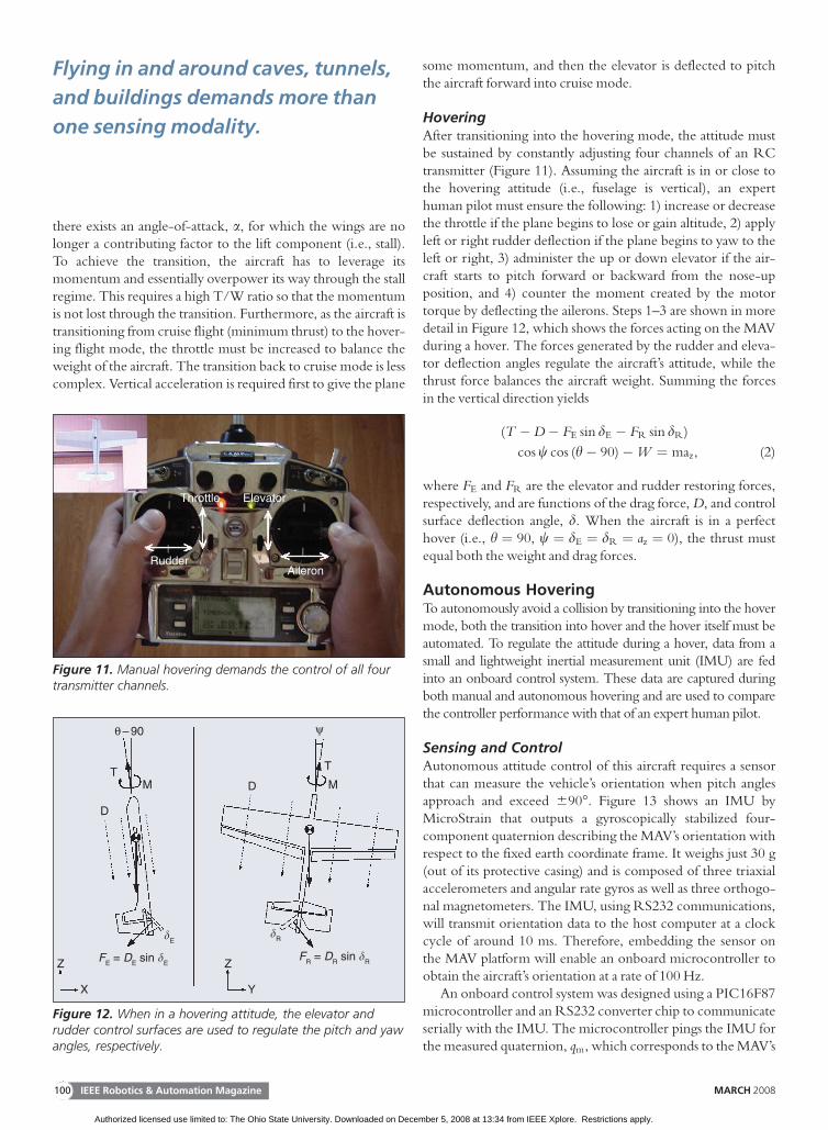
HoveringAfter transitioning into the hovering mode, the attitude mustbe sustained by constantly adjusting four channels of an RCtransmitter (Figure 11). Assuming the aircraft is in or close tothe hovering attitude (i.e., fuselage is vertical), an experthuman pilot must ensure the following: 1) increase or decreasethe throttle if the plane begins to lose or gain altitude, 2) applyleft or right rudder deflection if the plane begins to yaw to theleft or right, 3) administer the up or down elevator if the air-craft starts to pitch forward or backward from the nose-upposition, and 4) counter the moment created by the motortorque by deflecting the ailerons. Steps 1–3 are shown in moredetail in Figure 12, which shows the forces acting on the MAVduring a hover. The forces generated by the rudder and eleva-tor deflection angles regulate the aircraft’s attitude, while thethrust force balances the aircraft weight. Summing the forcesin the vertical direction yields
(T �D� FE sin dE � FR sin dR)
cos w cos (h� 90)�W ¼ maz, (2)
where FE and FR are the elevator and rudder restoring forces,respectively, and are functions of the drag force, D, and controlsurface deflection angle, d. When the aircraft is in a perfecthover (i.e., h ¼ 90, w ¼ dE ¼ dR ¼ az ¼ 0), the thrust mustequal both the weight and drag forces.
Autonomous HoveringTo autonomously avoid a collision by transitioning into the hovermode, both the transition into hover and the hover itself must beautomated. To regulate the attitude during a hover, data from asmall and lightweight inertial measurement unit (IMU) are fedinto an onboard control system. These data are captured duringboth manual and autonomous hovering and are used to comparethe controller performance with that of an expert human pilot.
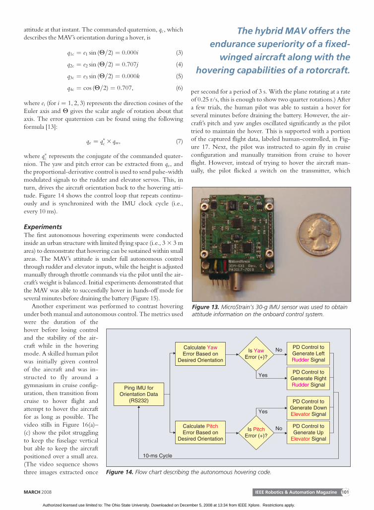
Sensing and ControlAutonomous attitude control of this aircraft requires a sensorthat can measure the vehicle’s orientation when pitch anglesapproach and exceed 690�. Figure 13 shows an IMU byMicroStrain that outputs a gyroscopically stabilized four-component quaternion describing the MAV’s orientation withrespect to the fixed earth coordinate frame. It weighs just 30 g(out of its protective casing) and is composed of three triaxialaccelerometers and angular rate gyros as well as three orthogo-nal magnetometers. The IMU, using RS232 communications,will transmit orientation data to the host computer at a clockcycle of around 10 ms. Therefore, embedding the sensor onthe MAV platform will enable an onboard microcontroller toobtain the aircraft’s orientation at a rate of 100 Hz.
An onboard control system was designed using a PIC16F87microcontroller and an RS232 converter chip to communicateserially with the IMU. The microcontroller pings the IMU forthe measured quaternion, qm, which corresponds to the MAV’s
ElevatorThrottle
RudderAileron
Figure 11. Manual hovering demands the control of all fourtransmitter channels.
Z
X
ZFE = DE sin �EFR = DR sin �R
M
D
D MT T
θ – 90 ψ
�E�R
Y
Figure 12. When in a hovering attitude, the elevator andrudder control surfaces are used to regulate the pitch and yawangles, respectively.
Flying in and around caves, tunnels,
and buildings demands more than
one sensing modality.
IEEE Robotics & Automation Magazine100 MARCH 2008
Authorized licensed use limited to: The Ohio State University. Downloaded on December 5, 2008 at 13:34 from IEEE Xplore. Restrictions apply.
attitude at that instant. The commanded quaternion, qc, whichdescribes the MAV’s orientation during a hover, is
q1c ¼ e1 sin (H=2) ¼ 0:000i (3)
q2c ¼ e2 sin (H=2) ¼ 0:707j (4)
q3c ¼ e3 sin (H=2) ¼ 0:000k (5)
q4c ¼ cos (H=2) ¼ 0:707, (6)
where ei (for i ¼ 1, 2, 3) represents the direction cosines of theEuler axis and H gives the scalar angle of rotation about thataxis. The error quaternion can be found using the followingformula [13]:
qe ¼ q�c 3 qm, (7)
where q�c represents the conjugate of the commanded quater-nion. The yaw and pitch error can be extracted from qe, andthe proportional-derivative control is used to send pulse-widthmodulated signals to the rudder and elevator servos. This, inturn, drives the aircraft orientation back to the hovering atti-tude. Figure 14 shows the control loop that repeats continu-ously and is synchronized with the IMU clock cycle (i.e.,every 10 ms).
ExperimentsThe first autonomous hovering experiments were conductedinside an urban structure with limited flying space (i.e., 3 3 3 marea) to demonstrate that hovering can be sustained within smallareas. The MAV’s attitude is under full autonomous controlthrough rudder and elevator inputs, while the height is adjustedmanually through throttle commands via the pilot until the air-craft’s weight is balanced. Initial experiments demonstrated thatthe MAV was able to successfully hover in hands-off mode forseveral minutes before draining the battery (Figure 15).
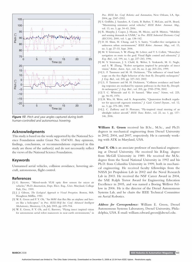
Another experiment was performed to contrast hoveringunder both manual and autonomous control. The metrics usedwere the duration of thehover before losing controland the stability of the air-craft while in the hoveringmode. A skilled human pilotwas initially given controlof the aircraft and was in-structed to fly around agymnasium in cruise config-uration, then transition fromcruise to hover flight andattempt to hover the aircraftfor as long as possible. Thevideo stills in Figure 16(a)–(c) show the pilot strugglingto keep the fuselage verticalbut able to keep the aircraftpositioned over a small area.(The video sequence showsthree images extracted once
per second for a period of 3 s. With the plane rotating at a rateof 0.25 r/s, this is enough to show two quarter rotations.) Aftera few trials, the human pilot was able to sustain a hover forseveral minutes before draining the battery. However, the air-craft’s pitch and yaw angles oscillated significantly as the pilottried to maintain the hover. This is supported with a portionof the captured flight data, labeled human-controlled, in Fig-ure 17. Next, the pilot was instructed to again fly in cruiseconfiguration and manually transition from cruise to hoverflight. However, instead of trying to hover the aircraft man-ually, the pilot flicked a switch on the transmitter, which
Is YawError (+)?
Is PitchError (+)?
PD Control toGenerate LeftRudder Signal
PD Control toGenerate RightRudder Signal
PD Control toGenerate DownElevator SignalYes
Yes
No
10-ms Cycle
No
PD Control toGenerate Up
Elevator Signal
Calculate PitchError Based on
Desired Orientation
Calculate YawError Based on
Desired Orientation
Ping IMU forOrientation Data
(RS232)
Figure 14. Flow chart describing the autonomous hovering code.
The hybrid MAV offers the
endurance superiority of a fixed-
winged aircraft along with the
hovering capabilities of a rotorcraft.
Figure 13. MicroStrain’s 30-g IMU sensor was used to obtainattitude information on the onboard control system.
IEEE Robotics & Automation MagazineMARCH 2008 101
Authorized licensed use limited to: The Ohio State University. Downloaded on December 5, 2008 at 13:34 from IEEE Xplore. Restrictions apply.
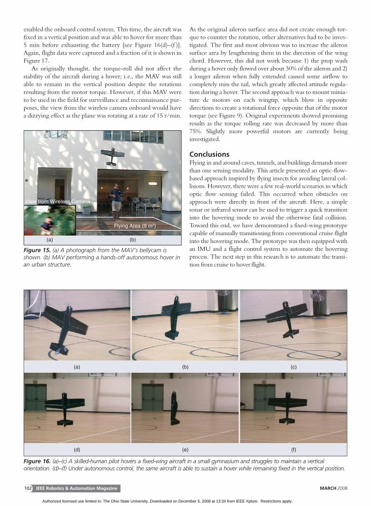
enabled the onboard control system. This time, the aircraft wasfixed in a vertical position and was able to hover for more than5 min before exhausting the battery [see Figure 16(d)–(f )].Again, flight data were captured and a fraction of it is shown inFigure 17.
As originally thought, the torque-roll did not affect thestability of the aircraft during a hover; i.e., the MAV was stillable to remain in the vertical position despite the rotationsresulting from the motor torque. However, if this MAV wereto be used in the field for surveillance and reconnaissance pur-poses, the view from the wireless camera onboard would havea dizzying effect as the plane was rotating at a rate of 15 r/min.
As the original aileron surface area did not create enough tor-que to counter the rotation, other alternatives had to be inves-tigated. The first and most obvious was to increase the aileronsurface area by lengthening them in the direction of the wingchord. However, this did not work because 1) the prop washduring a hover only flowed over about 30% of the aileron and 2)a longer aileron when fully extended caused some airflow tocompletely miss the tail, which greatly affected attitude regula-tion during a hover. The second approach was to mount minia-ture dc motors on each wingtip, which blow in oppositedirections to create a rotational force opposite that of the motortorque (see Figure 9). Original experiments showed promisingresults as the torque rolling rate was decreased by more than75%. Slightly more powerful motors are currently beinginvestigated.
ConclusionsFlying in and around caves, tunnels, and buildings demands morethan one sensing modality. This article presented an optic-flow-based approach inspired by flying insects for avoiding lateral col-lisions. However, there were a few real-world scenarios in whichoptic flow sensing failed. This occurred when obstacles onapproach were directly in front of the aircraft. Here, a simplesonar or infrared sensor can be used to trigger a quick transitioninto the hovering mode to avoid the otherwise fatal collision.Toward this end, we have demonstrated a fixed-wing prototypecapable of manually transitioning from conventional cruise flightinto the hovering mode. The prototype was then equipped withan IMU and a flight control system to automate the hoveringprocess. The next step in this research is to automate the transi-tion from cruise to hover flight.
(a) (b) (c)
(d) (e) (f)
Figure 16. (a)–(c) A skilled-human pilot hovers a fixed-wing aircraft in a small gymnasium and struggles to maintain a verticalorientation. (d)–(f) Under autonomous control, the same aircraft is able to sustain a hover while remaining fixed in the vertical position.
Flying Area (9 m2)
View from Wireless Camera
(a) (b)
Figure 15. (a) A photograph from the MAV’s bellycam isshown. (b) MAV performing a hands-off autonomous hover inan urban structure.
IEEE Robotics & Automation Magazine102 MARCH 2008
Authorized licensed use limited to: The Ohio State University. Downloaded on December 5, 2008 at 13:34 from IEEE Xplore. Restrictions apply.
AcknowledgmentsThis study is based on the work supported by the National Sci-ence Foundation under Grant No. 0347430. Any opinions,findings, conclusions, or recommendations expressed in thisstudy are those of the author(s) and do not necessarily reflectthe views of the National Science Foundation.
Keywords
Unmanned aerial vehicles, collision avoidance, hovering air-craft, autonomous, flight control.
References[1] G. Barrows, ‘‘Mixed-mode VLSI optic flow sensors for micro air
vehicles,’’ Ph.D. dissertation, Dept. Elect. Eng., Univ. Maryland, CollegePark, Dec. 1999.
[2] J. J. Gibson, The Ecological Approach to Visual Perception. Boston, MA:Houghton Mifflin, 1950.
[3] W. E. Green and P. Y. Oh, ‘‘An MAV that flies like an airplane and hov-ers like a helicopter,’’ in Proc. IEEE/RSJ Int. Conf. Advanced IntelligentMechatronics, Monterey, CA, July 2005, pp. 699–704.
[4] W. E. Green, P. Y. Oh, and G. Barrows, ‘‘Flying insect inspired visionfor autonomous aerial robot maneuvers in near-earth environments,’’ in
Proc. IEEE Int. Conf. Robotics and Automation, New Orleans, LA, Apr.2004, pp. 2347–2352.
[5] S. Griffiths, J. Saunders, A. Curtis, B. Barber, T. McLain, and R. Beard,‘‘Maximizing miniature aerial vehicles,’’ IEEE Robot. Automat. Mag.,vol. 13, no. 3, pp. 34–43, 2006.
[6] R. Murphy, J. Casper, J. Hyams, M. Micire, and B. Minten, ‘‘Mobilityand sensing demands in USAR,’’ in Proc. IEEE Industrial Electronics Conf.(IECON), 2000, vol. 1, pp. 138–142.
[7] D. H. Shim, H. Chung, and S. S. Sastry, ‘‘Conflict-free navigation inunknown urban environments,’’ IEEE Robot. Automat. Mag., vol. 13,no. 3, pp. 27–33, Sept. 2006.
[8] M. V. Srinivasan, S. W. Zhang, M. Lehrer, and T. S. Collett, ‘‘Honeybeenavigation en route to the goal: Visual flight control and odometry,’’ J.Exp. Biol., vol. 199, no. 1, pp. 237–243, 1996.
[9] M. V. Srinivasan, J. S. Chahl, K. Weber, S. Venkatesh, M. G. Nagle,and S. W. Zhang, ‘‘Robot navigation inspired by principles of insectvision,’’ Robot. Auton. Syst., vol. 26, no. 2, pp. 203–216, 1999.
[10] L. F. Tammero and M. H. Dickinson, ‘‘The influence of visual land-scape on the free flight behavior of the fruit fly Drosophila melanogaster,’’J. Exp. Biol., vol. 205, pp. 327–343, 2002.
[11] L. F. Tammero and M. H. Dickinson, ‘‘Collision avoidance and land-ing responses are mediated by separate pathways in the fruit fly, Drosoph-ila melanogaster,’’ J. Exp. Biol., vol. 205, pp. 2785–2798, 2002.
[12] T. C. Whiteside and G. D. Samuel, ‘‘Blur zone,’’ Nature, vol. 225,pp. 94–95, 1970.
[13] B. Wie, H. Weiss, and A. Arapostathis, ‘‘Quaternion feedback regula-tor for spacecraft eigenaxis rotations,’’ J. Guid. Control Dynam., vol. 12,no. 3, pp. 375–380, 1989.
[14] J. C. Zufferey and D. Floreano, ‘‘Fly-inspired visual steering of anultralight indoor aircraft,’’ IEEE Trans. Robot., vol. 22, no. 1, pp. 137–
146, 2006.
William E. Green received his B.Sc., M.Sc., and Ph.D.degrees in mechanical engineering from Drexel Universityin 2002, 2004, and 2007, respectively. He is currently work-ing with ATK in Maryland, USA.
Paul Y. Oh is an associate professor of mechanical engineer-ing at Drexel University. He received his B.Eng. degreefrom McGill University in 1989. He received the M.Sc.degree from the Seoul National University in 1992 and hisPh.D. from Columbia University in 1999, both in mechani-cal engineering. He received faculty fellowships from theNASA Jet Propulsion Lab in 2002 and the Naval ResearchLab in 2003. He received the NSF Career Award in 2004,the SAE Ralph Teetor Award for Engineering EducationExcellence in 2005, and was named a Boeing Welliver Fel-low in 2006. He is the director of the Drexel AutonomousSystems Lab, and he chairs the IEEE Technical Committeeon Aerial Robotics.
Address for Correspondence: William E. Green, DrexelAutonomous Systems Laboratory, Drexel University, Phila-delphia, USA. E-mail: [email protected].
105
100
95
90
Pitc
h (°
)
80
80
750 5 10
Time (s)15 20 25
0 5 10Time (s)
15 20 25
20
15
10
5
–5
–10
–15
–20
Pitc
h (°
)
0
AutonomousHuman-Controlled
AutonomousHuman-Controlled
Figure 17. Pitch and yaw angles captured during bothhuman-controlled and autonomous hovering.
IEEE Robotics & Automation MagazineMARCH 2008 103
Authorized licensed use limited to: The Ohio State University. Downloaded on December 5, 2008 at 13:34 from IEEE Xplore. Restrictions apply.