Embed Size (px)
Citation preview

Opti-Amp USB Op cal Bio-Amplifi er System So ware Manual Version 2.0
Intelligent Hearing SystemsTelephone: (305) 668-6102 • Fax: (305) 668-6103
Toll Free: 1-800-IHSYSTEMS (1-800-447-9783)E-mail: [email protected]
Web: h p://www.ihsys.com

Op -Amp USB Installa on and So ware Manual Op cal Bio-Amplifi er System So ware Manual Version 2.0
©2016 Intelligent Hearing Systems
Revision: March 4, 2016Part Number: M012010
Manufacturer:Intelligent Hearing Systems6860 SW 81st StMiami, FL 33143U.S.A.

Op -Amp USB So ware Manual i
Safety InstructionsComplying with the following warnings and cau on statements will ensure safe opera on of the equipment as well as the safety of the users and test subjects. These no ces may be repeated as appropriate further into the manual:
W :This symbol iden fi es condi ons or prac ces that may present danger to the test subject and/or user.
C :This symbol iden fi es condi ons or prac ces that could result in damage to the equipment or in incorrect results.
A :This symbol iden fi es condi ons or prac ces that could lead to non-hazardous, yet unintended or unexpected, consequences.
Due to safety considera ons for human subjects, the hardware and all other electrically a ached devices must be plugged into an Isola on Transformer compliant with the interna onal standard IEC-60601. This is required for proper galvanic isola on.
The computer and printer used with the system must be connected to the same Isola on Transformer.
Third party equipment that was not provided or approved by IHS must not be connected to the same Isola on Transformer.
Isola on Transformers must not be placed on the fl oor in order to prevent the accidental ingress of fl uids.
Any devices located in the pa ent area, connected to the Intelligent Hearing Systems devices, must be compliant with the requirements of IEC 60601-1.
Power cables shall be connected to electrical outlets approved by interna onal standard IEC-60601. This is necessary for grounding reliability and proper isola on.
The biomedical department of your ins tu on must make sure that the leakage current test results comply with the requirements of your region.
Computers connected to a network need to be tested for leakage current while connected to the network.A network connec on may aff ect total leakage current.
The main power switch must remain accessible; do not posi on the Op -Amp USB device in such a way that hinders access to the power switch.
The System is not explosion proof and must not be used in presence of fl ammable gases or substances.
Hazardous electrical output may occur. This equipment is for use by qualifi ed personnel only.
The operator must not touch any of the electrical cables and the pa ent at the same me.
Before connec ng any cables or accessories, ensure that all power switches are in the ‘OFF’ posi on.
Verify all hardware connec ons before every use.
The system is not protected against defi brillators. Remove pa ent connec ons before defi brilla on. If defi brilla on occurs, retest the system for leakage current to ensure safety.
Although they are electrically isolated, pa ent connec ons are not intended for direct cardiac contact.
To minimize the risk of infec on, DO NOT reuse any device labeled as disposable; dispose of these items properly a er use.
Follow your ins tu on’s guidelines for skin prepara on. When performing skin prepara on and/or impedance reduc on in human subjects, only use supplies approved by the FDA or by your ins tu on.
Follow your ins tu on’s procedures when cleaning the equipment. A cloth, damp with Isopropyl alcohol may be used to clean and disinfect the Op -Amp USB device. Do not use strong cleaners that may damage the plas c enclosure. Do not allow any cleaning solu on to get inside electronic components and connectors.
Do not have the equipment inspected or repaired by non-authorized third party technician. All problems must be solved using the Intelligent Hearing Systems servicing department or an IHS designated agent. Non-compliance will void the equipment warranty.
Due to cross-contamina on considera ons, systems used on animal subjects should never be used to test human subjects.
10D OAE probes have a built-in equalizer, making it possible to swap probes with minimal eff ect on the results. 10B+ Microphone probes require an external equalizer, making them system specifi c. Never swap the 10B+ Microphone with another unit.

Op -Amp USB So ware Manual ii
Read and follow the instruc ons in this Hardware Installa on sec on when installing or transferring the system.
Follow the special precau ons for EMC when installing an bringing the equipment into service.
Do not operate with damaged cords or plugs. Inspect all connec on cords periodically for fraying or other damage.
Plug all equipment into an earth grounded outlet, if available. These are usually marked with a green dot next to the connec ng pins.
When the equipment is installed adjacent or stacked with third party equipment, the performance should be observed to verify normal opera on.
Portable and mobile RF equipment may aff ect the performance of the equipment. Turn off or remove RF equipment in close proximity as needed.
Do not operate with broken equipment. Inspect all devices and a ached accessories for signs of damage before use.
When connec ng all cables, do not force the connec on. Damage to the hardware may occur.
Only connect cables and accessories as specifi ed in the provided manuals, and as instructed by IHS provided documenta on. Failure to do so may result in increased emissions or decreased immunity.
Read and follow the instruc ons provided in the user manuals to ensure safe and proper use of the equipment.
Ensure that the pa ent electrode leads are correctly a ached and connected to the appropriate lead socket. Inver ng the electrode connec ons may cause incorrect or mis-interpreta on of results.
The OAE probe must always be used in combina on with an ear p. Never place the OAE probe on the ear canal directly.
Non-medical equipment that will be connected to any part of the system or a ached devices must comply with the necessary standards for you area, if applicable.
Turn off all equipment before connec ng or disconnec ng accessories.
Turn off and disconnect all equipment and all parts of the equipment when performing maintenance and cleaning.
Be aware that in environments with mul ple users, the default protocol may be changed by others. Always verify the parameters before acquiring. Keeping a separate copy of specifi c parameters, and loading those before each use will help avoid this situa on.
Op -Amp USB So ware Manual iii
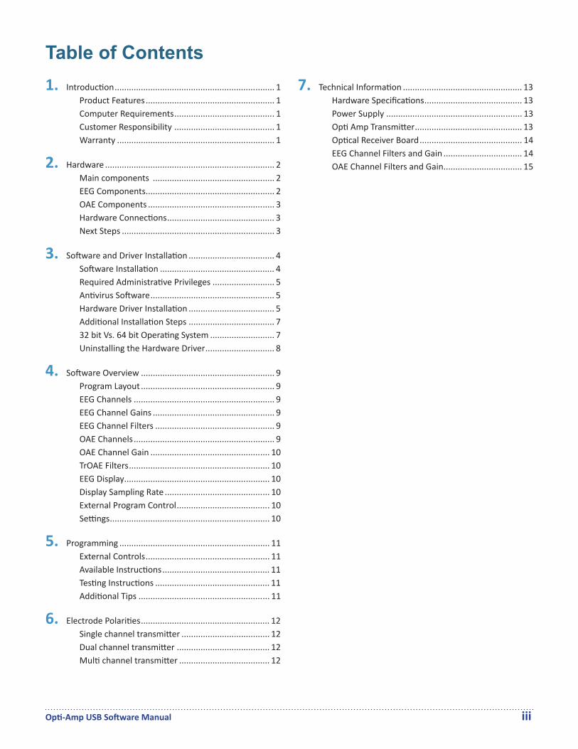
Table of Contents7. Technical Informa on .................................................. 13
Hardware Specifi ca ons ......................................... 13Power Supply ......................................................... 13Op Amp Transmi er ............................................. 13Op cal Receiver Board ........................................... 14EEG Channel Filters and Gain ................................. 14OAE Channel Filters and Gain ................................. 15
1. Introduc on ................................................................... 1Product Features ...................................................... 1Computer Requirements .......................................... 1Customer Responsibility .......................................... 1Warranty .................................................................. 1
2. Hardware ....................................................................... 2Main components ................................................... 2EEG Components ...................................................... 2OAE Components ..................................................... 3Hardware Connec ons ............................................. 3Next Steps ................................................................ 3
3. So ware and Driver Installa on .................................... 4So ware Installa on ................................................ 4Required Administra ve Privileges .......................... 5An virus So ware .................................................... 5Hardware Driver Installa on .................................... 5Addi onal Installa on Steps .................................... 732 bit Vs. 64 bit Opera ng System ........................... 7Uninstalling the Hardware Driver ............................. 8
4. So ware Overview ........................................................ 9Program Layout ........................................................ 9EEG Channels ........................................................... 9EEG Channel Gains ................................................... 9EEG Channel Filters .................................................. 9OAE Channels ........................................................... 9OAE Channel Gain .................................................. 10TrOAE Filters ........................................................... 10EEG Display ............................................................. 10Display Sampling Rate ............................................ 10External Program Control ....................................... 10Se ngs ................................................................... 10
5. Programming ............................................................... 11External Controls .................................................... 11Available Instruc ons ............................................. 11Tes ng Instruc ons ................................................ 11Addi onal Tips ....................................................... 11
6. Electrode Polari es ...................................................... 12Single channel transmi er ..................................... 12Dual channel transmi er ....................................... 12Mul channel transmi er ...................................... 12
Op -Amp USB So ware Manual 1
1IntroductionWelcome to the Intelligent Hearing Systems family of customers. Please be sure to read all the enclose documenta on. Doing so will allow you to use the equipment safely. It will also allow you to maximize the benefi ts from this great investment.
of the product become necessary a er the end of the warranty period, the user must consult IHS before such repair or replacement. If the product is in need of repair, do not use it un l all repairs are completed, the unit is func oning properly and is appropriately tested. The owner of this product has sole responsibility for the following:
• Any malfunc on resul ng from improper use, • Maintenance or repairs done by other than IHS, • Any malfunc on caused by parts that are
damaged or modifi ed by anyone other than IHS authorized personnel.
WarrantyOp -Amp is manufactured by Intelligent Hearing Systems Corp. (IHS), Miami, FL and is sold under the warranty herein set forth. The warranty is extended only to the buyer purchasing the device from IHS or an authorized dealer-representa ve.IHS warrants this product to be free from defects in workmanship and material under normal use and service and shall conform to its original specifi ca ons for a period of one (1) year from the date of delivery. The liability of IHS under this warranty is limited, at its sole discre on, to replacing, repairing or issuing credit (adjusted to refl ect age and use of the product) for a system or por on thereof provided that (a) IHS is no fi ed in wri ng within 30 days following the discovery of a defect by the buyer, (b) the defec ve device is returned to IHS, and (c) IHS’s examina on of the device shall disclose to its sa sfac on that (i) the device has not been repaired or altered by anyone, (ii) any defect has not been caused by misuse, neglect or accident, and (iii) the device has not been used for other than normal use.THIS WARRANTY IS EXPRESSLY IN LIEU OF ALL OTHER WARRANTIES, EXPRESS OR IMPLIED, WHETHER STATUTORY OR OTHERWISE, INCLUDING AN IMPLIED WARRANTY OF MERCHANTABILITY OR FITNESS FOR A PARTICULAR PURPOSE. IN NO EVENT SHALL INTELLIGENT HEARING SYSTEMS CORP. BE LIABLE FOR ANY INCIDENTAL OR CONSEQUENTIAL DAMAGES RESULTING FROM THE USE OF THIS PRODUCT OR CAUSED BY ANY DEFECT, FAILURE, OR MALFUNCTION OF THE PRODUCT, WHETHER A CLAIM FOR SUCH DAMAGE IS BASED UPON WARRANTY, CONTRACT NEGLIGENCE OR OTHERWISE.
Product FeaturesOp -Amp USB is an accessible op cal bio-amplifi er system. Some of its features are:
• Up to eight programmable EEG or OAE channels• Programmable Gain, High Pass Filters and Low
Pass Filters• Built in electrical noise notch fi lter customized
for your power supply,Op -Amp USB works under the Windows© 7, 8 and 10 opera ng systems. This manual assumes that you are familiar with the basic opera on of these opera ng systems and their capabili es. Please refer to the opera ng system manuals when necessary.
Computer RequirementsThe following list describes the minimum computer requirements for installing and opera ng the IHS so ware.
• Windows Based Opera ng System ◦ Desktop or Laptop with a 32 or 64 bit
Windows 7, 8, 8.1 or 10 opera ng systems. ◦ Virtual Machine, such as Parallels© or
VMWare©, running one of the opera ng systems listed above.
• 4 GB of RAM.• 10 MB of Hard Drive Space for program storage.• WXGA graphics, 1280 x 768 resolu on.• 1 USB port.• Mouse or Other Poin ng Device.
The Op -Amp USB hardware requires a Windows© compa ble opera ng system with a USB port. Because of diff erences between manufacturers, IHS cannot guarantee compa bility with all computers. If you experience any diffi cul es, contact Intelligent Hearing Systems Customer’s Service at 1-800-447-9783, and a representa ve will assist you.
Customer Responsibility The equipment, its components and included so ware shall perform reliably as long as it is operated and maintained in accordance with the instruc ons contained in the manuals, associated labels and inserts. A defec ve component must not be used. New IHS-manufactured parts should promptly replace broken, missing or worn parts. If you suspect a part of the equipment to be defec ve or if you need addi onal informa on, please contact IHS. The responsibility of IHS is limited by the warranty as stated in this manual. Should the repair or replacement

Op -Amp USB So ware Manual 2
2HardwareThe following items may be included in your system. The items included will depend on system confi gura on.
Main components This is main hardware included in every system, along with so ware and driver installa on media.Opti-Amp USB Box
Fig. 1. - Op -Amp USB Box (M012300)
Power Supply
Fig. 2. - USB Power Supply (M011111)
Power Cord
Fig. 3. - USB Medical Grade Power Cord (M011112)
USB Cable
Fig. 4. - USB Cable (M0111113)
EEG ComponentsThe following components are included for systems that incorporate EEG func onality.Opti-Amp Transmitter
One or the other will be included depending on system confi gura on:
Fig. 5. - 1 Channel Op -Amp Transmi er (M013009P)
Fig. 6. - 2 Channel Op -Amp Transmi er (M013010P)
Fig. 7. - Mul -Channel Op -Amp Transmi er (M013020P)
The Mul -Channel Op -Amp transmi er pictured above has four channels; others may have 6 or 8 channels depending on system confi gura on.Fiber Optic Cable
A fi ber op c cable with one op cal lead per channel is included with each unit.
Fig. 8. - 2-Channel Fiber Op c Cable (M013200S)

Hardware
Op -Amp USB So ware Manual 3
Systems are supplied with a 2.5 meters cable with the number of channels applicable to the system confi gura on. The following versions of the Fiber Op c cables are available:
• M013210S: 1 Channel, 2.5 meters• M013200S: 2 Channel, 2.5 meters• M013204S: 4 Channel, 2.5 meters• M013206S: 6 Channel, 2.5 meters• M013208S: 8 Channel, 2.5 meters• M013211S: 1 Channel, 5 meters• M013201S: 2 Channel, 5 meters• M013214S: 4 Channel, 5 meters• M013216S: 6 Channel, 5 meters• M013218S: 8 Channel, 5 meters
OAE ComponentsAn OAE microphone or probe is supplied per channel of OAE included in the system confi gura on.10B+ OAE Microphone
Fig. 9. - 10B+ OAE Probe (M032100)
10D Probe
Fig. 10. - 10D OAE Probe (M032103)
Hardware Connections
1 Make sure that the Op -Amp USB box is in the OFF posi on (O) before proceeding.
2 Connect the Power supply 5-pin plug into the power socket at the back of the Op -Amp USB.
3 Connect the Medical Grade power cord plug to the Power Supply socket
4 For systems with EP channels, connect the Fiber Op c cable to the back of the Op -Amp USB and to the Op -Amp Transmi er box. Make sure to connect the 3-pin power plug, as well as all the available fi ber channels.
5 For systems with OAE channels, plug the OAE probe socket to the back of the Op -Amp USB.
6 Connect the Op -Amp USB to external equipment using the front BNC connectors as needed.
7 Connect the USB cable to the back of the Op -Amp USB and to an available port on the computer to be used. If the computer is ON, the computer connec on light will illuminate.
Next StepsDo not turn the equipment ON un l the so ware and hardware drivers are installed. Refer to the next sec on for instruc ons on how to install them. If your PC was provided by IHS with your purchase, you may skip the installa on of so ware and hardware drivers as these were done in-factory before it was shipped.

Op -Amp USB So ware Manual 4
3 Software and Driver InstallationIf the computer being used with the system was not purchased with it, or your hard drive had to be reforma ed, you will need to install the so ware package and hardware drivers. It is impera ve to follow these direc ons closely and in the proper sequence or the system may not func on properly. It is recommended to start by installing the so ware applica ons and driver before turning ON the hardware. If you purchased the computer from Intelligent Hearing Systems, you may skip this sec on as the so ware programs and hardware driver have been already installed.
Software Installation
1 Connect the So ware Drive to a free USB port on the computer. The opera ng systems should recognize and install the drive automa cally.
2 Select the “Open Folder” op on from the AutoPlay window. Note that the drive le er and the listed op ons may not be exactly the same as in the following image.
If AutoPlay does not open, then browse the computer using Windows Explorer and view the contents of the drive. Click on “File Explorer” for Windows 10, “This PC” for Windows 8, or “Computer” for Windows 7 to open windows explorer, then fi nd the removable drive.
3 From the list of fi les and folders in the explorer window, double click on the fi le called “Setup”. Note that the fi le will show the executable extension in some computers and will read “Setup.exe” instead. The explorer windows may only show icons as opposed to the list detailed view shown below.
4 If User Account Controls is ac ve in your computer, you will be asked if to confi rm that you want to execute the setup program. Click on “Yes”.
5 If you want to install the so ware to a loca on other than the default, change the directory on the top fi eld of the setup program. The default loca on is the “Op Amp” folder in your “C” drive.
6 If upda ng a previous installa on, check the “Update Only” box at the bo om right of the window. For new installa ons, or to overwrite an exis ng one, make sure this box is NOT checked.

So ware and Driver Installa on
Op -Amp USB So ware Manual 5
7 Click on the [Start] bu on.
8 When Done, click on the [Exit] bu on.
Required Administrative PrivilegesIn computers joined to a domain, standard users will need to have full read and write privileges to the installa on folder to achieve full func onality of the so ware. System administrators will need to enable full access to this folder by either edi ng the privileges at the local level, or by using group policy.
• ‘C:\Op Amp’: This loca on stores the programs and se ngs. The loca on may be modifi ed at the me of installa on. The installa on path must not contains spaces. All users must have full rights to this folder.
In addi on, there must not be restric ons in place for users to access USB devices, as they would prevent proper opera on. Installing the hardware driver using the included installa on u li es (‘IHSDriverInstalla on32.exe’ or ‘IHSDriverInstalla on64.exe’, depending on the OS bits) is highly recommended to allow for standard users to change USB ports without the need of an Informa on Services technician. Alterna vely, plug the device into all possible USB ports during setup, and ensure the device is detected properly, so that users are not impacted by a change of port.
Antivirus SoftwareThere are no known incompa bili es with IHS hardware or so ware to operate in a computer with An virus So ware installed. The IHS so ware has been tested, and found to be fully opera onal and without issue, in computers using an virus so ware from Symantec, Trend Micro, McAff ee, AVG, and Microso .If at any point your an virus program reports a fi le inside the installa on folder to be infected, please contact IHS to confi rm the validity of the fi le and/or obtain a replacement. You may also create a scanning excep on for the IHS so ware installa on folder and the pa ent data folder men oned in the previous topic.
Hardware Driver InstallationPre-installing the USB Driver
The latest versions of the Op -Amp so ware include a driver pre-installa on u lity; this is the preferred method. To pre-install:
1. Browse the contents of the computer hard drive using Windows Explorer. In Windows 7, click on the “Computer” item from the Start Menu; in Windows 8, click on “File Explorer” from the Start Menu (Metro interface), then select “This PC”.
2. Double click on the local “C” drive, then fi nd the original so ware installa on folder, “Op Amp”.
3. Inside that folder, fi nd the program called “IHSDriverInstalla on32.exe” for 32 bit systems, or “IHSDriverInstalla on64.exe” for 64 bit systems. Note that some computers may not show the “.exe” extension.
4. Run the program that corresponds to the number of bits of your opera ng system to install the drivers. Running the wrong version will result in an error. If an error occurs, simply run the other program.
5. Once completed, you may connect and turn ON the Op Amp Hardware, it should be recognized automa cally.
If the IHSDriverInstalla on programs are not present, then this may be an older version of the so ware and there are two op ons:
• Install a so ware update, then proceed with the installa on as previously outlined. Note that not all systems will support an update, consult with IHS support personnel for details.
• Install the driver manually as described below.Installing the USB Driver Manually
To Install the hardware drivers on your computer manually, follow the steps that correspond to your computer’s opera ng system:On Windows 8 and Windows 10
1. Make sure the Op -Amp USB hardware is properly connected to the computer and power.
2. Turn the Op -Amp USB ON. Windows may automa cally try to fi nd the driver in the Microso update site. If Windows cannot fi nd the driver, con nue with the rest of this guide.
3. Move the mouse pointer to the bo om le corner of the screen and right-click to get a pop-up menu.

So ware and Driver Installa on
Op -Amp USB So ware Manual 6
4. Select the ‘Device Manager’ from the list5. Look for the ‘Unknown’ device from the list
and right click on it. Select the “Update Driver So ware” op on from the menu.
6. Click on the “Browse my computer” bu on.
7. Select the folder where the IHS so ware is installed. By default, this folder is “C:\Op Amp”. Click [Next].
8. Once completed, a message will appear showing the results of the installa on. Some hardware versions may use unsigned drivers. If you are prompted about this during installa on, press “Con nue Anyway” to proceed.
9. The device is now listed under the Universal Serial Bus Controllers.
On Windows 7
1. Make sure the Op -Amp USB hardware is properly connected to the computer and power.
2. Turn the Op -Amp USB ON. Windows may try to automa cally fi nd the driver in the Microso update site. If Windows cannot fi nd the driver, con nue.
3. In the start menu, search for the device manager.
4. Select the ‘Device Manager’ from the op ons in the ‘Control Panel’.
5. Look for the ‘Unknown device’ from the list and right click on it. Select the “Update Driver”op on from the menu.
6. Click on the “Browse my computer” bu on.

So ware and Driver Installa on
Op -Amp USB So ware Manual 7
7. Select the folder where the IHS so ware is installed. By default, this folder is “C:\IHSPROGS”. Click [Next].
8. Once completed, a message will appear showing the results of the installa on. Some hardware versions may use unsigned drivers. If you are prompted about this during installa on, press “Con nue Anyway” to proceed.
9. The device is now listed under the Universal Serial Bus controllers sec on.
Installation under a Virtual Machine
When running a Windows opera ng system as a virtual machine under another opera ng system such as Mac OS X or Linux, make sure the USB device is connected to the virtual machine, bypassing the host opera ng system. For instruc ons on how to do this, consult the documenta on of the virtualiza on so ware. Once the hardware is connected to the virtual machine, follow the steps that correspond to the guest Windows opera ng system in use.
Additional Installation StepsSome versions of the Windows opera ng system turn off USB Root hubs by default to conserve power a er a period of user inac vity. This may cause the device to stop working properly, even when the USB hub resumes opera ons a er sleep, hiberna on, or long computer inac vity. To correct this problem:For Windows 7, click on the [Start] bu on, then type “Power Op ons” in the search fi eld. For Windows 8 and 10, right click on the bo om corner of the screen to show the administra ve menu.
1. Choose the “Power Op ons” item from the list.
2. Click on “Change Plan Se ngs” for the currently selected power plan.
3. Click on the “Change Advanced Power Se ngs”op on.
4. Expand the USB Se ngs sec on by clicking on the [>] or [+] sign next to it.
5. Change the “USB Selec ve suspend se ng”values to “Disabled”.
6. Click [Apply], the [OK].In addi on, you may want to prevent the computer from going into sleep or hiberna on modes so it can run uninterrupted.
32 bit Vs. 64 bit Operating SystemThe so ware can operate in both, 32 bit and 64 bit, environments, based on an internal so ware se ng. The latest so ware will change this se ng automa cally as needed; a one- me warning window will alert the user of the change. Older so ware requires to have the se ng changed manually. If neither op on is available, a so ware update is required. Contact IHS for details and availability.
Changing the OS Bits manually
Before changing the bits, fi nd out how many bits your opera ng system uses. Right click on the ‘This PC’(‘Computer’ on Windows 7) and select proper es from the context menu. One of the fi elds of the proper es window will specify whether the opera ng system is 32 bits or 64 bits. Note that most newer computers operate in 64 bits.To change the opera ng system mode of the IHS so ware do the following:
1. Browse the computer’s C drive to fi nd the so ware installa on folder, “Op Amp” by default.
2. Inside that folder, fi nd the applica on called “IHSHWSet.exe” and run it.
3. Enter the system password, ‘ihs’ is the default.4. Change the ‘OS bits’ drop down to the correct
op on, matching the informa on found in the computer proper es window.

So ware and Driver Installa on
Op -Amp USB So ware Manual 8
5. Click on the [Save] bu on, then [Close]. The se ngs will be applied next me the so ware is started.
Uninstalling the Hardware DriverOn rare occasions, you may need to uninstall the hardware driver from the computer.
Using the uninstaller
If the driver was installed using the pre-installer, then this op on will be available; otherwise, uninstall the driver manually.
1. In the computer’s control panel, click on “Uninstall a Program”, found in the programs sec on.
2. In the Programs and Features window, look for a program called “Windows Driver Package - Intelligent Hearing Systems”.
3. Select the item, then click Uninstall/Change.4. Complete the uninstalla on Wizard.
To uninstall manually
If the original installa on was not completed using the pre-installer, the driver will need to be deleted manually. Complete this opera on with the device plugged in, then unplug it a er comple ng it.
1. Open the Device Manager window. It can be accessed either from the control panel, or by opening the computer management console.
2. In the Universal Serial Bus Controllers sec on of the device list, search for a device that starts with the name “Intelligent Hearing Systems Op Amp Device”, the rest of the name will depend of the version of pla orm installed.
3. Right click on the device and from the pop-up menu, choose “Uninstall”.
4. In the confi rma on window that appears, make sure to check the box that reads “Delete the driver so ware from this device”. Failing to check this box will result in a par al uninstall, leaving the old driver in the windows database; if this happens, reinstall manually and then uninstall the driver again.
5. Click [OK] to confi rm and fi nish uninstalling.

Op -Amp USB So ware Manual 9
4Software OverviewIf the so ware is not already installed in your computer, follow the steps on page 4. The so ware is accessible from the Windows start menu under the [programs > Op Amp]folder. You may also access the program by browsing to the installa on directory. It is recommended that you create a shortcut to the program on the desktop for easy access.
Program LayoutThe Op -Amp so ware shows a control sec on for each installed amplifi er channel. A maximum of 8 channels may be added to the USB box assembly. The so ware allows for easy switching of gain and fi lter se ngs for each channel independently. The program layout will change depending on the number of channels purchased with the Op -Amp, the following fi gure shows a setup for a 2-channel system.
Fig. 11. - Op -Amp main screen, 2-channel system
EEG ChannelsEach EEG channel will be labeled as such be the channel designa on marker as shown in Fig. 12. EEG channels contain drop-down selectors for the Gain, High Pass fi lter and Low Pass fi lter. The Line Filter can be turned ON (checked) and OFF (unchecked) using the check box on the lower right hand corner. The built in line fi lter will be pre-set at factory to be 50 or 60 Hz depending on the electrical supply in your area.
Fig. 12. - EEG Channel Layout
EEG Channel GainsThe Op -Amp USB provides eight (8) EEG Gain se ngs: 5, 10, 25, 50, 100, 150, 200, and 300 K. To select the desired gain se ng, simply select it from the drop-down menu.Listed Gains are the standard gains normally included in the device, actual gain values may vary if your system was special ordered. Refer to the drop down gain menus for actual again values that apply to your system. Gain se ngs may be custom made to any eight values between 5 K and 300 K.
Fig. 13. - EEG Channel Gains
EEG Channel FiltersThe Op -Amp USB provides eight (8) high pass fi lter se ngs between 1 and 500 Hz, and eight low pass fi lter se ngs between 30 and 5000 Hz. To select the desired fi lter se ng, simply select it from the drop-down menu.Listed fi lters are the standard fi lters normally included in the device, actual fi lter values may vary if your system was special ordered. Refer to the drop down fi lter menus for actual fi lter values that apply to your system. Filter se ngs may be custom made to any 16 values between 0.5 Hz and 10 kHz.
Fig. 14. - High Pass and Low Pass EEG Channel Se ngs
OAE ChannelsEach OAE channel will be labeled as such be the channel designa on marker as shown in Fig. 15. OAE channels contain se ngs for the Gains. The TrOAE Filter can be turned ON and OFF using the check box on the lower right hand corner.
Fig. 15. - OAE Channel Layout
So ware Overview
Op -Amp USB So ware Manual 10
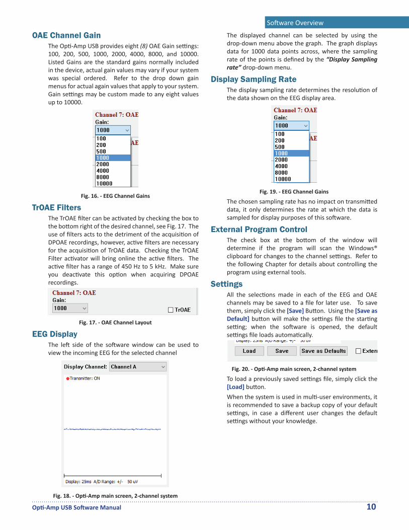
OAE Channel GainThe Op -Amp USB provides eight (8) OAE Gain se ngs: 100, 200, 500, 1000, 2000, 4000, 8000, and 10000. Listed Gains are the standard gains normally included in the device, actual gain values may vary if your system was special ordered. Refer to the drop down gain menus for actual again values that apply to your system. Gain se ngs may be custom made to any eight values up to 10000.
Fig. 16. - EEG Channel Gains
TrOAE FiltersThe TrOAE fi lter can be ac vated by checking the box to the bo om right of the desired channel, see Fig. 17. The use of fi lters acts to the detriment of the acquisi on of DPOAE recordings, however, ac ve fi lters are necessary for the acquisi on of TrOAE data. Checking the TrOAE Filter ac vator will bring online the ac ve fi lters. The ac ve fi lter has a range of 450 Hz to 5 kHz. Make sure you deac vate this op on when acquiring DPOAE recordings.
Fig. 17. - OAE Channel Layout
EEG DisplayThe le side of the so ware window can be used to view the incoming EEG for the selected channel
Fig. 18. - Op -Amp main screen, 2-channel system
The displayed channel can be selected by using the drop-down menu above the graph. The graph displays data for 1000 data points across, where the sampling rate of the points is defi ned by the “Display Sampling rate” drop-down menu.
Display Sampling RateThe display sampling rate determines the resolu on of the data shown on the EEG display area.
Fig. 19. - EEG Channel Gains
The chosen sampling rate has no impact on transmi ed data, it only determines the rate at which the data is sampled for display purposes of this so ware.
External Program ControlThe check box at the bo om of the window will determine if the program will scan the Windows® clipboard for changes to the channel se ngs. Refer to the following Chapter for details about controlling the program using external tools.
SettingsAll the selec ons made in each of the EEG and OAE channels may be saved to a fi le for later use. To save them, simply click the [Save] Bu on. Using the [Save as Default] bu on will make the se ngs fi le the star ng se ng; when the so ware is opened, the default se ngs fi le loads automa cally.
Fig. 20. - Op -Amp main screen, 2-channel system
To load a previously saved se ngs fi le, simply click the [Load] bu on.When the system is used in mul -user environments, it is recommended to save a backup copy of your default se ngs, in case a diff erent user changes the default se ngs without your knowledge.

Op -Amp USB So ware Manual 11
5ProgrammingExternal Controls
The Op -Amp parameters can also be controlled from another applica on using the Windows Clipboard to send and receive informa on. To enable this op on, select the “Enable External Program Control” check box on the lower right side of the Op -Amp dialog box. If you wish this op on ac vated the next me you run the Op -Amp so ware, save the current se ngs as the Default se ngs.
Fig. 21. - External Program Control ac va on check box
Available InstructionsThe following are the instruc ons that the Op -Amp program will parse and understand when placed on the Windows® clipboard.
• OPTIAMP-CHx-GAIN=n: This instruc on will change the gain of channel ‘x’ to the value of the ‘n ’ op on from its corresponding drop-down menu. E.g. ‘OPTIAMP-CH3-GAIN=2’ will set the gain of the third channel to 10 K (the second op on).
• OPTIAMP-CHx-HP=n: This instruc on changes the high pass fi lter of channel ‘x’ to the value of the ‘n ’ op on from its corresponding drop-down menu. E.g. ‘OPTIAMP-CH1-HP=6’ will set the high pass fi lter of the fi rst channel to 150 Hz (the sixth op on)
• OPTIAMP-CHx-LP=n: This instruc on changes the low pass fi lter of channel ‘x’ to the value of the ‘n ’ op on from its corresponding drop-down menu.
• OPTIAMP-CHx-SWITCH=ON: This instruc on will ac vate the line fi lter of channel ‘x’.
• OPTIAMP-CHx-SWITCH=OFF: This instruc on will deac vate the line fi lter of channel ‘x’.
• OPTIAMP-SAVE: This op on will save the current set of se ngs of all channels as the default.
• OPTIAMP-CLOSE: This op on closes the applica on.
Testing InstructionsThe simplest way to test the communica ons with the so ware module is to run Notepad and type in some instruc ons. Posi on the Op -Amp so ware and the Notepad window in such a way that you can see both program windows at the same me on your computer screen. Type an Op -Amp instruc on in Notepad, highlight the instruc on and press [Ctrl] + [C] to copy the text to the Clipboard. You should see the appropriate value change on the Op -Amp dialog window.
Additional TipsIt is important not to lock out the Windows Clipboard by con nuously reading or wri ng to the Clipboard. This will not allow other applica ons to write or read from the Clipboard. A delay or interrupt method may be used in order to allow the Op -Amp applica on me to read and write to the Clipboard. It is also important to read the format of the data currently on the clipboard. If another applica on places graphical data on the clipboard, reading it as a text may cause your applica on to crash.The Op -Amp program allows you to save the current se ngs as defaults. The next me you run the Op -Amp program, all the default se ngs will be loaded and the Op -Amp hardware programmed accordingly. The only way to make sure that all the se ngs are set as your applica on desires is to program all the se ngs each me you run your applica on. If someone changes the se ngs and saves them as the default se ngs, your applica on will not know if those values have been changed or not. Unless you are sure that no one can modify your se ngs, you should not assume that the loaded default values are the ones you want to use
Op -Amp USB So ware Manual 12
6Electrode PolaritiesSingle channel transmitter
The single channel transmi er box has three electrode posi ons: a Red, Blue, and a Black. The func ons of each posi on need to be physically switched on the Op -Amp transmi er by fl ipping the ‘Le -Right’ lever to the correct posi on. Failing to change the lever posi on may result in an inverted recording; however, the response will be acquired regardless of se ngs.
• When the Switch is set to “Right” on the Amplifi er:
◦ The Red electrode is the inver ng electrode (-).
◦ The Blue electrode is the ground. ◦ The Black electrode is the non-inver ng
electrode (+).• When the Switch is set to “Le ” on the Amplifi er:
◦ The Red electrode is the ground. ◦ The Blue electrode is the inver ng
electrode (-). ◦ The Black electrode is the non-inver ng
electrode (+).
Dual channel transmitterThe dual channel transmi er box has fi ve electrode posi ons: two Red, two Blue, and one Black. In These type of transmi ers, the Red posi ons are always the inver ng electrodes, the Blue posi ons are always the non-inver ng electrodes, and the Black posi on is always the ground, shared between all channels. The polarity of the electrode posi ons will not change regardless of so ware se ngs. One set of Red and Blue posi ons corresponds to each channel, clearly marked on the amplifi er itself as A and B.
Multi channel transmitterSystems with more than two acquisi on channels use a large Op -Amp transmi er box, which can house up to eight pre-amplifi er channels. The unit will have a variable amount of Red and Blue electrode sockets, based on the number of channels. All Red sockets correspond to inver ng electrodes (-), and all Blue sockets correspond to non-inver ng electrodes (+) for their respec ve channels. The Black electrode socket is always the ground electrode shared between all channels.

Op -Amp USB So ware Manual 13
6Technical InformationHardware Specifi cations
GPart Number M012300 Opera ng Temperature 15°C to 40°C Storage Temperature 0°C to 50°C Rela ve Humidity 15% to 90% at 40°C
Non-Condensing Atmospheric Pressure None Specifi edMode of Opera on Con nuousDegree of Mobility Portable EquipmentVibra on and Shock N/A Expected Life me 5 Years from date of
manufacture
E SRated Input Current 5A, 2.5A, 0.5A Rated Frequency 50/60 HzRated Input Voltage +5V, +15V, -15V DCRated Max Input Power N/A Fuse Type N/A Fuse Ra ng N/A
Power SupplyG
Part Number M011111Opera ng Temperature 0°C to 70°CStorage Temperature -40°C to 85°CRela ve Humidity 5% to 95% at 40°C
Non-CondensingAl tude 0 - 3048 m
(0 - 10000 )Mode of Opera on Con nuous
E SRated Input Current 1.3 ARated Input Frequency 50-60 HzRated Input Voltage 100-240 V~Rated Max Output Power 45WRated Output Voltage +5 V, +15 V, -15 V DCRated Output Current 5 A, 2.5 A, 0.5 A
(correspondingly)Protec on Overcurrent and
OvervoltageApproval IEC 60601-1
Opti Amp TransmitterS
M013009P, M013010P, M013020P.Opera ng Temperature 0°C to 70°C.Rela ve Humidity 15% to 90%
at 40°C Non-Condensing.Atmospheric Pressure 500-1050 nPa.Common Mode Rejec on ≥ 105 dB @ 1 kHz
≥ 120 dB @ 50/60 Hz with notch fi lter ON.
Noise Level ≤ 0.333 μV RMS (1-3000 Hz).
Input Impedance > 5 MΩ.Coupling AC.Built-in Impedance Test 1 kHz.Isola on Fiber Op c Cable
for signal, DC-to-DC transformer for power.
Power 15 V DC, 140 mA.
Transmitter Filters and Gain
Gainx10
High Pass Filter2-pole Butterworth
fc: 0.3 Hz
Low Pass Filter2-pole Butterworth
fc: 10000 Hz
Inst. Amplifierx100
Signal
FOSignal

Technical Informa on
Op -Amp USB So ware Manual 14
Optical Receiver BoardThe Receiver board, internal to the pla orm, contains the op cal receiver units, low-pass fi lters, high-pass fi lters and gain se ngs. Depending on the number of acquisi on channels of your system, connectors will be available on the back plate of the pla orm.
G SAmplifi ca on (x1000) 5, 10, 25, 50, 100, 150,
200, 300
F SLow Pass (-6 dB/Oct.) 30, 100, 300, 500, 1000,
1500, 3000, 5000High Pass (-6 dB/Oct.) 1, 10, 30, 50, 100, 150,
300, 500Line Filter (-12 dB/Oct.) On/Off (50 or 60 Hz)
EEG Channel Filters and Gain
Programmable HPF1, 10, 30, 450, 100, 150,300, or 500 Hz; 1-pole
50 or 60 Hz2-pole
Anti-Aliasing LPF4th Order Butterworth
fc: 10000 Hz
Notch FilterON/OFF
ON
OFF
Low Pass Filter16 KHz passive 4-pole
BNCOut
16 Bit A/D
Display
FOSignal
Programmable LPF30, 100, 300, 500, 1k,
1.5k, 3k, or 5k Hz; 1-pole
Programmable Gain5k, 10k, 25k, 50k, 100k,
150k, 200k, or 300k
Prog.LPF ≤ 1500 Hz
YES
NO
Anti-Aliasing LPF4th Order Butterworth
fc: 2000 Hz
Technical Informa on
Op -Amp USB So ware Manual 15
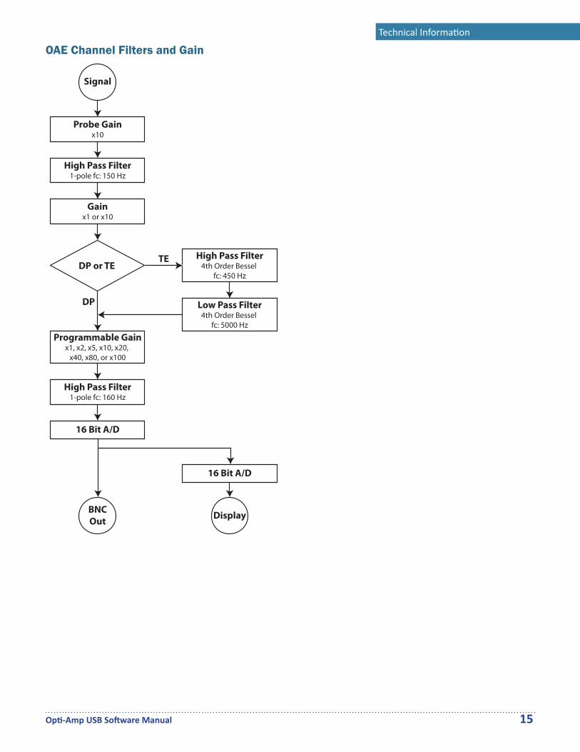
OAE Channel Filters and Gain
Gainx1 or x10
Programmable Gainx1, x2, x5, x10, x20,
x40, x80, or x100
High Pass Filter4th Order Bessel
fc: 450 Hz
Low Pass Filter4th Order Bessel
fc: 5000 Hz
DP or TETE
DP
Probe Gainx10
High Pass Filter1-pole fc: 160 Hz
16 Bit A/D
High Pass Filter1-pole fc: 150 Hz
Signal
BNCOut
16 Bit A/D
Display